

Equivalent Minimum Hydrogen Consumption of Fuzzy Control-Based Fuel Cells: Exploration of Energy Management Strategies for Ships
School of Naval Architecture, Ocean and Energy Power Engineering, Wuhan University of Technology, Wuhan 430063, China
*
Author to whom correspondence should be addressed.
Batteries 2024, 10(2), 66; https://doi.org/10.3390/batteries10020066
Submission received: 29 November 2023
/
Revised: 30 January 2024
/
Accepted: 7 February 2024
/
Published: 18 February 2024
(This article belongs to the Special Issue Modeling, Reliability and Health Management of Lithium-Ion Batteries)
Abstract
:Aiming to solve the problems of insufficient dynamic responses, the large loss of energy storage life of a single power cell, and the large fluctuation in DC (direct current) bus voltage in fuel cell vessels, this study takes a certain type of fuel cell ferry as the research object and proposes an improved equivalent minimum hydrogen consumption energy management strategy, based on fuzzy logic control. First, a hybrid power system including a fuel cell, a lithium–iron–phosphate battery, and a supercapacitor is proposed, with the simulation of the power system of the modified mother ship. Second, a power system simulation model and a double-closed-loop PI (proportion integration) control model are established in MATLAB/Simulink to design the equivalent hydrogen consumption model and fuzzy logic control strategy. The simulation results show that, under the premise of meeting the load requirements, the control strategy designed in this paper improves the Li-ion battery’s power, the Li-ion battery’s SOC (state of charge), the bus voltage stability, and the equivalent hydrogen consumption significantly, compared with those before optimization, which improves the stability and economy of the power system and has certain practical engineering value.
1. Introduction
Nowadays, the increasingly serious environmental pollution and energy problems urgently require internal-combustion-engine-based vehicles to be upgraded or replaced; so, new energy vehicles based on hybrid power and fuel cells have gradually stepped onto the stage and continue to be innovated. The shipping industry is one of the main sources of global greenhouse gas emissions. The development of clean energy ships powered by fuel cells has attracted wide attention. Fuel cells have the advantages of being clean, pollution-free, and low-noise, but they have some disadvantages, such as an insufficient dynamic response performance and fast performance decay. Limited by the characteristics of a single energy source, a variety of energy sources and bidirectional DC converters are usually mixed to form a hybrid ship to improve the flexibility, stability, and economy of the ship and enhance its adaptability to complex sea conditions through the reconfiguration of power system energy.
Compared with traditional ships, hybrid ships have great development potential and broad application prospects. First of all, hybrid ships use clean energy and renewable energy, which significantly reduces the emission of harmful gases, helps to mitigate global climate change and improve air quality, and has important environmental significance; secondly, the use of natural resources for energy replenishment instead of traditional fossil fuels not only reduces the cost, but also has strong adaptability and can obtain better navigation results in complex waters and marine conditions; finally, hybrid ships have great potential, as, through their technological innovation and intelligent control, they can improve the efficiency of their energy utilization, reduce their energy consumption, and achieve the win–win situation of sustainable development and economic benefits.
A hybrid energy storage system (HESS) has the functions of shaving peaks and filling valleys, compensating for sudden changes in operating conditions, and improving power quality. According to the principle of converting energy into electric energy, it can be divided into mechanical, electrochemical, and electromagnetic energy storage, comprehensively considering the factors of cycle life, energy density, reliability, configuration cost, etc., to maintain the busbar voltage in the safety margin [1] and, at the same time, to meet the demand of continuous power supply for the ship. The energy-type and power-type energy storages are mixed to form the HESS. In recent years, domestic and international experts have focused on the research of composite energy storage technology composed of lithium batteries/supercapacitors.
The load demand of hybrid ships cannot be satisfied by the accumulation of power sources alone, and reasonable energy management strategies need to be designed to meet the complex working conditions while taking into account the service life of the equipment [2,3]. In the past, according to the degree of hybridization, they were divided into switching control strategies and power-following strategies [4]. Current energy management strategies are mainly based on rules, optimization, and artificial intelligence algorithms.
Rule-based energy management strategies are classified into deterministic and fuzzy rules. Han et al. [5] proposed a strategy to continuously adjust the battery SOC for power allocation based on typical working conditions, which reduces the hydrogen consumption of the fuel cell and maximizes the efficiency of the system compared with the traditional load-tracking control; Zou et al. [6] designed a charging-and-discharging control strategy for the SOC of the energy storage element to avoid overcharging and over-discharging of the energy storage system. However, the working condition setting is relatively specific and the universality of the control strategy cannot be verified. Sun [7] proposed a strategy based on fuzzy control and dynamic coordination, which improved the gas engine efficiency and reduced the system response time for the gas–electric hybrid power system of an inland waterway tugboat. The setting of both deterministic and fuzzy rules needs to be based on expert experience, which makes it difficult to achieve global optimization and has many limitations.
Optimized control strategies are divided into real-time optimization (RTO) and global optimization (GO) for the optimization problem, to formulate the function of optimization objectives and constraints and to optimize the power allocation of multiple energy sources to operate at the best operating point. The real-time optimization strategy is based on the real-time state parameters of the ship to carry out online control, so that the performance indexes reach the real-time optimum. Usually, there is an equivalent consumption minimization strategy (ECMS), model predictive control (MPC), and robust control (RC), which can be used to optimize the performance of the ship. Hu Dongliang [8] used equivalent energy minimization consumption as the objective function, the sailing direction and time as the constraints, and the whale optimization algorithm for dynamic optimization, and the simulation results showed a reduction in the ship’s energy consumption. The global optimization strategy needs to be chosen based on the ship’s static historical data and known sailing conditions, and the common ones are dynamic programming (DP), genetic algorithm (GA), and particle swarm optimization (PSO), as well as these algorithm’s variants. Zhang [9] decoupled the optimization problem to obtain the corresponding solution, then used the non-dominated sorting-based genetic algorithm II (NSGA-II) to find the Pareto frontier, and finally used fuzzy decision-making to obtain the optimal solution. Due to the limitations of a single intelligent optimization algorithm when searching time and space, in recent years, multiple algorithms have often been improved or fused to achieve the optimal solution, but the amount of computation and the time consumption have also increased accordingly.
Energy management strategies based on artificial intelligence algorithms mainly utilize machine learning, deep learning, and deep reinforcement learning algorithms to control each power source. Wu [10] applied deep Q-learning (DQL) algorithms to the energy management problem of a parallel electric vehicle, and the results showed that it was better than the Q-learning method in terms of training time and convergence rate. However, since this strategy is still in its infancy, the theory still needs to be verified by a large number of simulation experiments. There are advantages and disadvantages of each method, and different methods can be synergized to achieve better control results.
The first section of this paper provides a brief overview of the background and significance of the research on new energy ships, the development of energy storage technology, and the current status of energy management strategies, and the remaining sections are structured as follows: the second section designs the topology of the composite energy storage system and models the important components; the third section introduces the transient optimization strategy and designs the energy management strategy in this paper, i.e., the fuzzy control-based equivalent minimum hydrogen consumption strategy, which is characterized by its use of fuzzy logic control to adaptively adjust the penalty factor of the hydrogen consumption model to realize the power allocation of the composite energy storage system; the fourth section introduces the typical working conditions and optimization model of this paper and designs the corresponding simulation experiments; and the fifth section validates the proposed method through the simulation model, and the results of the simulation experiments are compared and analyzed and discussed. By comparing the SOC of Li-ion batteries, the output power of fuel cells and Li-ion batteries, the bus voltage stability, and the equivalent hydrogen consumption, the effectiveness of the proposed strategy is verified to solve the problems of poor dynamic characteristics of fuel cells and the inability of Li-ion batteries to bear high-frequency load fluctuations, so as to improve the quality of the power.
2. Power System Modeling and Simulation
2.1. Topology Design
The composite energy storage topology plays a crucial role in determining the energy transfer efficiency, control strategy, and configuration cost. In the marine sector, three main composite energy storage topologies are commonly used: passive, active, and semi-active [11]. The passive topology involves directly connecting lithium batteries and supercapacitors in parallel, supplying power to the load through an inverter. This topology was primarily used in early demonstrations but is now less common due to the performance advantages of pure battery systems [12,13]. The semi-active topology features one component controlled by a DC/DC converter while the other passively handles the load power, making it the most widely used configuration. The active topology can be further classified into series and parallel structures. The series architecture, although connected to the DC bus and energy storage element, faces challenges with constant current loads. On the other hand, the parallel architecture, with two DC/DC converters connected to two energy storage elements, offers high control accuracy but is more challenging to control with lower system efficiency. For practical ship applications, this paper selects the semi-active battery topology, where the battery connects to the DC/DC converter and the supercapacitor links directly to the DC bus. The energy storage system’s topology is illustrated in Figure 1.
2.2. Modeling and Simulation
The fuel cell is a complex nonlinear system with a large number of parameters and a complex dependency relationship between them, so it is necessary to establish a corresponding model according to the specific problem. In the design of a hybrid energy management strategy, the complex internal physicochemical reaction process can be ignored, and it is only necessary to summarize the historical data, repeatedly correct the parameters, and obtain the empirical formula to reflect the output characteristics of the fuel cell, i.e., empirical (analytical) modeling. This paper cites the proton exchange membrane model proposed by [14,15], and the concentration polarization voltage loss is not considered. The output voltage of the fuel cell is shown in Equation (1):
where is the open-circuit voltage of the fuel cell, V; is the activation voltage loss, V; and is the ohmic voltage loss, V, respectively, as shown in Equations (2)–(4).
where is the Tafel slope, is the output current of the fuel cell, A; is the exchange current, which is set to 0.9837 A in this paper; is the response time of the fuel cell, which is set to 1 s in this paper; is the internal resistance of the fuel cell, which is set to 0.025 Ω in this paper; is the Laplace operator; is the voltage constant; and is the potential of the fuel cell, V, shown in Equation (5).
where is the temperature, which is set to 318 K in this paper; and are the inlet pressures of hydrogen and oxygen, MPa; and is the Faraday constant and is the ideal gas constant, which were set to 8.3145 J/(mol∙K) and 96,485 A∙s/mol, respectively.
The charging and discharging voltages of the battery are shown by Equations (6) and (7) according to the equivalent circuit model proposed in the literature [16,17,18]:
where is the constant voltage, V; is the polarization resistance, Ω; is the maximum battery capacity, Ah; is the dynamic current of the battery, A; is the low-frequency dynamic current of the battery, A; is the exponential voltage, V; is the exponential capacity, Ah−1; and is the unit time step.
The output voltage of the supercapacitor is shown by Equation (8) according to the literature [19]:
where is the number of supercapacitors in series; is the number of supercapacitors in parallel; is the number of supercapacitor electrode layers; is the permittivity of material; is the permittivity of free space; is the interfacial area between the electrodes and electrolytes, m2; is the electric charge, C; is the radius of the molecule, nm; is the molar concentration, mol/m3; is the internal resistance of the supercapacitor, Ω; and is the supercapacitor current, A.
In this paper, a simple, reliable, and energy-efficient half-bridge bidirectional DC/DC converter is selected, and its main structure is shown in Figure 2 below.
This half-bridge structure is mainly composed of a capacitor C, an inductor L, a resistor R, and an IGBT transistor. Boost mode or buck mode can be selected as per the requirements. Since there is a lag between the response of the power supply system and the input from the load, this lag can lead to response interruptions and voltage fluctuations [20], which are undesirable in the case of electric motor power supply [21] and can be avoided by limiting the slope of the optimal power input from the control strategy [22]. The reference power of the fuel cell is divided by the voltage to obtain its reference current, and the difference between the reference current and the measured current is regulated by the PI to determine the duty cycle of the DC/DC converter.
Boost mode: Transistor conducts, capacitor automatically releases power to ensure that the bus voltage is stable, and the other voltage stores power in inductor L during operation. When is disconnected, inductor L releases the stored power and supplies bus and capacitor together with . The duty cycle can be found by Equation (9) as follows:
where is the duty cycle, is a switching cycle, and is the conduction time of during a switching cycle. In buck mode, the variation in voltage with the duty cycle is shown in Equation (10) as follows:
Buck mode: Unlike boost mode, transistor operates continuously in the disconnected state. When is on, the high-voltage side stores the electrical energy in inductor L to provide electrical energy to the low-voltage side . When is off, diode turns on, and inductor L releases the stored electrical energy to the low-voltage side . When is disconnected, diode conducts and inductor L releases the stored electrical energy to the high-voltage side . The voltage relationship in buck mode is shown in Equation (11):
3. Mathematical Modeling of Optimization Problems
3.1. Fundamental Principle
In contrast to the global optimization strategy, which requires prediction of all working conditions of a ship’s sailing cycle and is constrained by variations among different ship types and uncertainties in real-time operations, the real-time optimization strategy focuses on determining the optimal operating point for each power source. It assesses and adjusts the current optimal operating mode based on real-time operational information. This approach considers the dynamic nature of the ship’s operations and allows for immediate adjustments to ensure efficient power utilization under changing conditions. By continuously evaluating and regulating the system based on real-time data, the real-time optimization strategy can enhance overall energy efficiency and performance, making it a valuable tool for optimizing energy management in marine applications.
The ECMS is a control strategy that determines a penalty factor by considering the SOC of the battery and the operating state of the diesel engine. It then converts the output power of the energy storage element into equivalent fuel consumption. The goal of the ECMS is to minimize the sum of the equivalent fuel consumption of the energy storage element and the actual fuel consumption of the diesel engine. Building upon this concept, the equivalent minimum hydrogen consumption strategy is derived. This strategy aims to minimize the sum of the hydrogen consumption of the energy storage element and the fuel cell. By optimizing the energy flow between different power sources based on these consumption metrics, the ECMS and its derivative strategies help improve the overall system efficiency and reduce operational costs in hybrid energy systems.
3.2. Strategic Design
The equivalent minimum hydrogen consumption strategy operates on the principle that the energy stored in the fuel cell for power generation will eventually be consumed, leading to a reduction in hydrogen consumption. This strategy establishes an equivalent relationship between the electrical energy consumption of the battery and supercapacitor and the hydrogen consumption of the fuel cell. By converting all energy consumption into hydrogen consumption, it calculates the equivalent hydrogen consumption at each moment. The optimization target of this strategy is to minimize the equivalent hydrogen consumption in each control cycle by adjusting the energy allocation of the power system in real time.
In this strategy, the control focuses on achieving the minimum equivalent hydrogen consumption under all operating conditions. When the battery state of charge (SOC) is high, the cost of battery power supply is low, leading the control strategy to prioritize battery power to meet the power demand. Consequently, the penalty factor decreases with an increase in battery SOC. Conversely, when the battery SOC is low, the cost of battery power supply is high, prompting the control strategy to favor the fuel cell for power supply. By dynamically adjusting the energy allocation based on real-time conditions and the equivalent hydrogen consumption target, this strategy aims to optimize system performance and efficiency in hybrid energy systems.
The calculation of equivalent hydrogen consumption can be performed according to Equation (12):
where is the hydrogen consumption of the fuel cell, and are the equivalent hydrogen consumption of the Li-ion battery and super-capacitor, respectively, and and are the penalty factors of the two. The SOC of the energy storage device can be controlled by adjusting the size of the penalty factor in real time, because the purpose of the supercapacitor is to cope with the peak of the demanded power under high-frequency working conditions to protect the service life of the fuel cell and the Li-ion battery, and its contribution compared to that of the other two is minimal and negligible; therefore, this paper chooses to use the PI controller to detect the supercapacitor SOC change, which is adjusted and added to the equivalent power consumption of the lithium battery. Therefore, Equation (12) can be modified to Equation (13):
The hydrogen consumption of the fuel cell is given by Equation (14) as follows:
where is the volumetric flow rate of hydrogen, g/s; is the pressure at the anode, which is designed to be 1.16 atmospheric pressure in this paper; is the molar mass of hydrogen, g/mol; is the molar gas constant; and is the reaction temperature, which is designed to be 318 K in this paper.
The equivalent hydrogen consumption of a lithium battery is given by Equation (15) below:
where is the real-time power of the Li-ion battery; is the average value of hydrogen consumption of the fuel cell; is the average power of the fuel cell; and represent the charging and discharging efficiency, respectively; and are the average efficiencies of charging and discharging, which are designed to be 0.8 in this paper; and ≥ 0 indicates that the Li-ion battery is being discharged. < 0 indicates that the Li-ion battery is charging. The charging and discharging efficiency is obtained from Equation (16) [23]:
where and are the internal resistance of the battery during charging and discharging, respectively, which is designed as a constant value of in this paper. In this paper, the selected lithium batteries are IFR 32650-5000 series, whose internal resistance is about 10 mΩ. According to the typical working condition load data, the average power to be borne by the composite energy storage system is allocated to the lithium-ion batteries, and it is calculated that it needs to be connected in series with 100 sections and 13 groups of lithium batteries of the selected model, and the customized R is taken as 0.077 Ω.
For the evaluation of lithium battery loss, it is derived from Equation (17) as follows:
where represents the magnitude of the charging and discharging power of the battery at the moment ; T is the complete time of a typical round of working conditions; and is the rated capacity of the battery pack.
3.3. Optimization Model
When solving the optimization problem, constraints need to be set on the optimization variables according to the actual situation, and the constraints set in this paper are as follows:
- Energy storage element charge state constraint
Lithium batteries and supercapacitors should not be overcharged and over-discharged, otherwise the internal aging of the components will accelerate, which will seriously affect the service life. So, it is necessary to set a reasonable range, as shown in Equation (18).
- Energy constraint
The total energy output of the composite energy storage system needs to satisfy the load demand as shown in Equation (19).
- Supercapacitor voltage constraint
The voltage of the supercapacitor determines the size of its energy storage and needs to satisfy the voltage constraints, as shown in Equation (20).
- Instantaneous power balance constraint
The instantaneous power of the power system needs to meet the power demand of the ship to ensure that there is no energy gap, otherwise it will lead to damage to the equipment, and in serious cases, the whole ship will be out of power. The balance constraints are shown in Equation (21).
The overall process of optimization is shown in Figure 3 below.
The mathematical model for the optimal solution is shown in Equation (22) below:
where and are the weight coefficients, both of which are taken as 0.5 in this paper.
3.4. Dual Closed-Loop PI Control Strategy
The implementation of a double closed-loop Proportional–Integral (PI) control strategy in this study aims to address the challenges associated with fluctuating fuel cell output power and prevent the overcharge and over-discharge of the lithium battery.
In this control strategy, the outer loop is responsible for adjusting the fuel cell’s output current based on the load power and the output of the equivalent minimum hydrogen consumption strategy of the Li-ion battery state of charge (SOC). This adjustment enables the system to prioritize charging or discharging the Li-ion battery at the appropriate times. On the other hand, the inner loop focuses on PI regulation of the bus voltage to enhance the stability of the fuel cell power output and ensure it aligns with the desired operating characteristics, including soft dynamic characteristics.
By incorporating this double closed-loop PI control strategy, this study aims to effectively manage the energy exchange in various working conditions. The control loop, which includes the PI controller, plays a crucial role in optimizing the system’s performance and efficiency. The control strategy depicted in Figure 4 provides a visual representation of how the control loops interact to achieve the desired outcomes in terms of power management and system stability.
In the modified power system where the fuel cell, lithium battery, and supercapacitor are utilized as composite energy storage devices, the implementation of the equivalent minimum hydrogen consumption strategy plays a critical role in controlling the ship’s performance and enhancing its overall economy. However, the effectiveness of this strategy heavily relies on the appropriate setting of the penalty factor, which significantly influences the actual control outcomes.
To address this issue and optimize the control strategy, an SOC balancing strategy is established. This strategy focuses on balancing the SOC of the battery through SOC equalization control. By adjusting the penalty factor through the battery SOC balancing control coefficient, SOC balancing can be achieved effectively.
The principle behind the SOC balancing strategy is that the cost of using the battery decreases as the battery SOC increases. In such cases, the energy management strategy tends to distribute the ship’s load between the energy storage system and the fuel cell. Conversely, when the battery SOC is low, the cost of using the battery increases, prompting the strategy to prioritize the fuel cell for load distribution.
By dynamically adjusting the penalty factor based on the battery SOC, the SOC balancing strategy aims to optimize the energy management process, enhance system efficiency, and ensure the effective utilization of the composite energy storage devices in the power system. This approach helps to maintain the balance between energy storage elements and power sources, leading to improved performance and economic benefits for the ship’s power system.
4. Penalty Factor Calculation
4.1. Fuzzy Logic Control Introduction
The utilization of fuzzy control as a control strategy in the hybrid power system discussed in the paper offers several advantages over traditional control methods. Fuzzy control is based on fuzzy rules and relies on the designer’s expertise or a comprehensive analysis of experimental data. By leveraging fuzzy sets theory and using natural language to handle imprecise input values, fuzzy control eliminates the need for precise mathematical models, making it suitable for systems with dynamic characteristics that are challenging to model accurately.
One of the key benefits of fuzzy control is its adaptability to systems with varying dynamic characteristics, as it does not require a precise mathematical model to achieve effective control. Moreover, fuzzy control is known for its ease of implementation, high optimization potential, robustness, and fault tolerance, making it a preferred choice for the hybrid power system control strategy in this paper [24].
Fuzzy control strategies are widely applied in various engineering fields, including autonomous driving in automobiles and robot control. The fuzzy controller, which is the central component of a fuzzy control system, plays a crucial role in determining the system’s performance and effectiveness.
The overall flow of a fuzzy logic control system, as depicted in Figure 5, showcases the process of utilizing fuzzy rules and linguistic variables to make control decisions. By incorporating fuzzy control in the hybrid power system, this paper aims to leverage its benefits in optimizing system performance, enhancing robustness, and facilitating efficient control in dynamic and complex operational scenarios.
4.2. Penalty Factors Based on Fuzzy Control
Next, formulation of the fuzzy control rule is carried out, and the design principles of the fuzzy controller are as follows:
- When the SOC of Li-ion batteries is low, the magnitude of the equivalence factor should be increased, and the equivalent hydrogen consumption of the same load should be increased; conversely, when the SOC of Li-ion batteries is high, the magnitude of the equivalence factor should be decreased to avoid overcharging the energy storage system.
- When the load power fluctuation is low, the size of the equivalence factor should be increased so that the fuel cell is mainly responsible for the load; as the load power fluctuation becomes large, the composite energy storage system needs to perform “peak shaving and valley filling”, and the size of the equivalence factor should be lowered to ensure the stability of the power output.
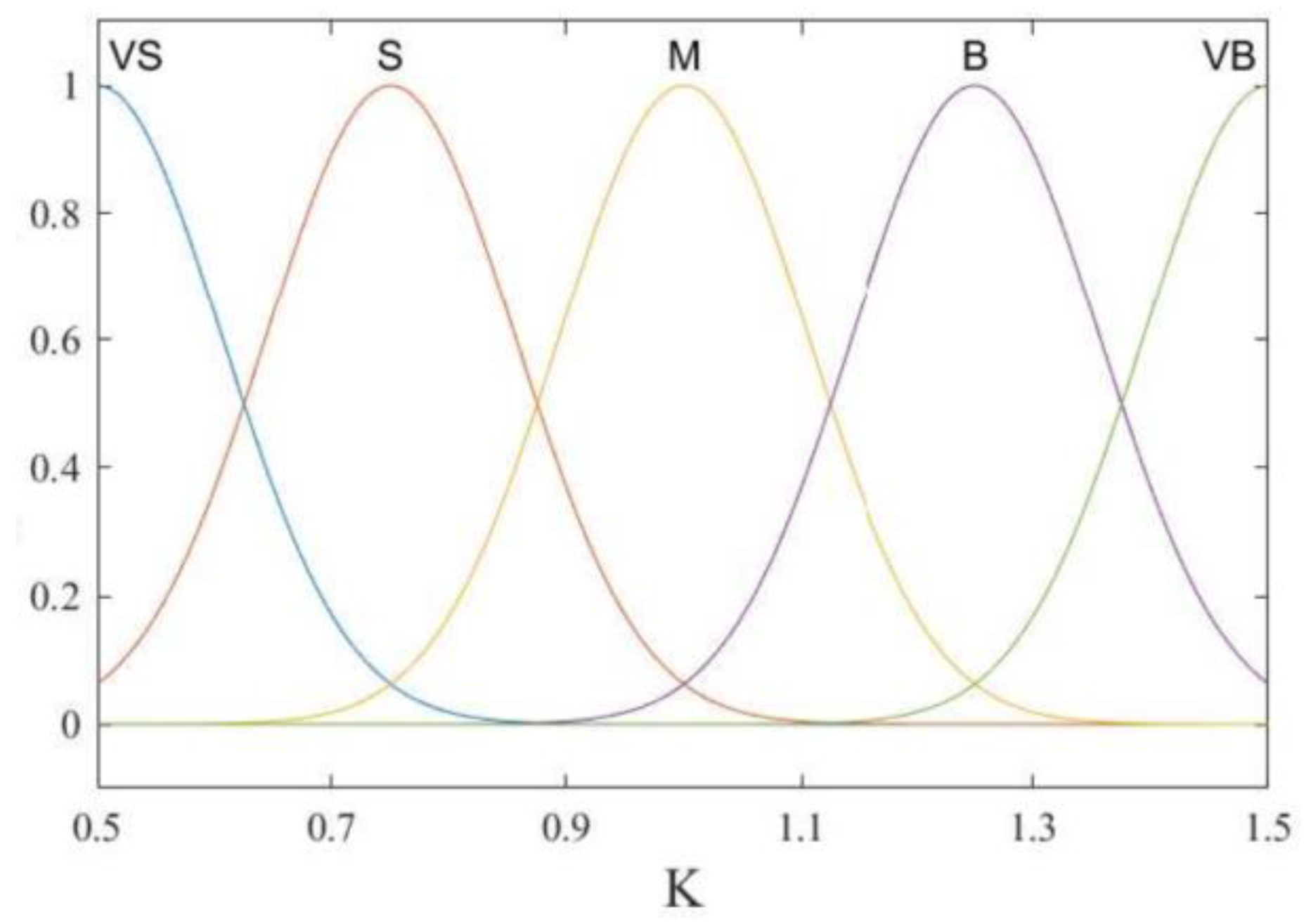
The inputs of the fuzzy controller are the Li-ion battery SOC and the ship load power , the output is the penalty factor, and the Gaussian function is chosen for the affiliation function because of its high sensitivity and stability. Li-ion battery SOC is the first input variable, and the fuzzy subsets {VS, S, M, B, VB} represent very small, small, medium, large, and very large, respectively; the normalized load power is the second input variable, and the set of seven fuzzy subsets {NB, NM, NS, ZE, PS, PM, PB} represent negative large, negative medium, negative small, zero, positive small, positive medium and positive large, respectively; the penalty factor is the output variable; and the fuzzy subset settings are the same as the Li-ion battery SOC to determine the number of fuzzy linguistic variables and subsets. The three variables of the affiliation function are shown in Figure 6, Figure 7 and Figure 8 below.
The fuzzy rule table is designed as shown in Table 1 below.
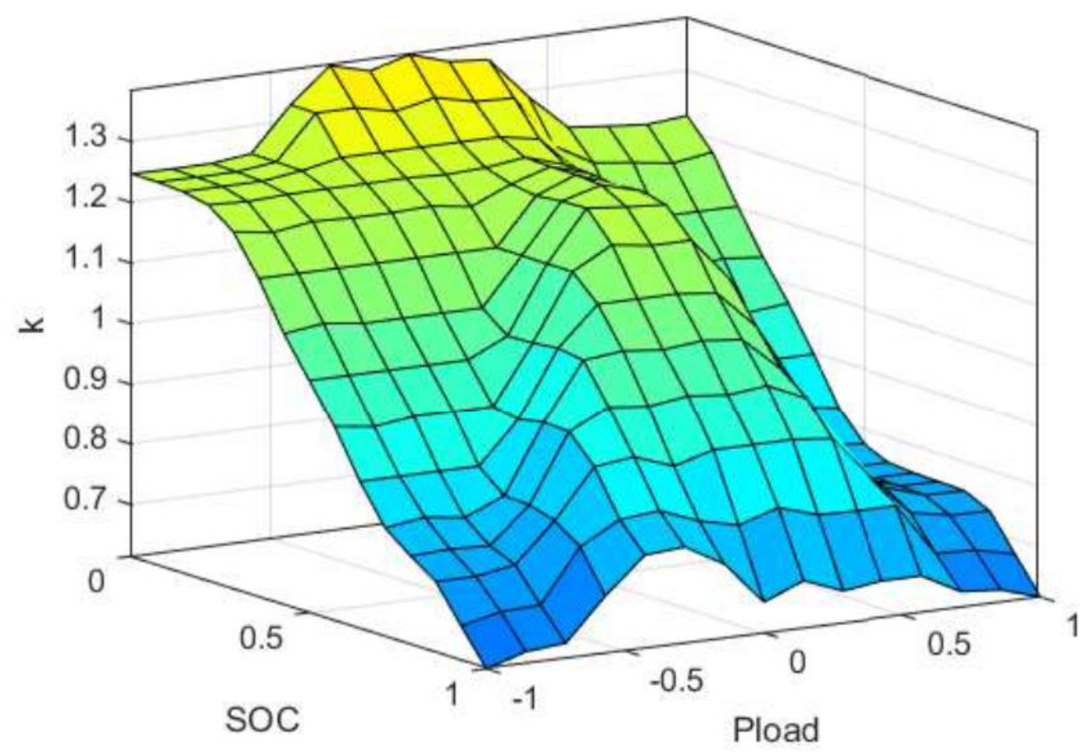
The fuzzy 3D surface map is shown in Figure 9, when the SOC of the lithium battery is small. With the increase in load power, the output of the fuzzy controller increases and then decreases, which means that when the load is low, the lithium battery can be protected to prevent it from over-discharging; the lithium battery can bear part of the load for the fuel cell at middle loads; and when the load is high, all the power sources need to bear the load, and the equivalence factor is reduced to the minimum. When the SOC of the Li-ion battery is large, as the load power gradually increases, the output of the fuzzy controller gradually decreases and tends to stabilize, which means that it protects the Li-ion battery from overcharging when the load is low, while all power sources are required to bear the load power under the middle and high loads. From the three-dimensional surface map, we can see that the system of fuzzy rules is basically in line with the design principle of the fuzzy controller.
4.3. Penalty Factors Based on S-Shaped Penalty Function
To verify the effectiveness of fuzzy logic control in calculating the penalty factor, a commonly used function for calculating the equivalence factor is presented below as a comparative. The S-type penalty function is a commonly used and improved penalty function, which is used three times when the battery is charging with ∆SOC ≥ 0 and four times when the battery is discharging with ∆SOC < 0. ∆SOC is obtained from Equation (23) as follows:
The penalty factor can be derived from Equation (24) as follows:
where a, b, c, d, and e are the adjustment factors; and represent the lower and upper limit values of the battery, respectively; is the deviation value of the battery’s power level; and is the penalty factor of the S-type penalty function. The curve of the S-type penalty function is shown below in Figure 10.
After fitting the function using Matlab, the relationship between the variation in the penalty factor and the residual power is obtained as shown in Equation (25):
5. Simulation Experiment Analysis
This study aims to enhance the efficiency of model validation and streamline the detection process of energy management strategies by simplifying the load demand under typical operational conditions. The simplified load power profile, as illustrated in Figure 11, provides insights into the load characteristics during different phases of ship operation.
Analyzing the simplified load power profile reveals that the average demand load is 4.36 kW, with a peak power of 11.2 kW. The operational timeline can be segmented as follows:
- From 0 to 90 s: The ship is engaged in constant-speed sailing, characterized by a relatively stable load demand.
- From 90 to 200 s: The ship undergoes docking, berthing, and disembarking operations, resulting in significant load variations. This phase represents maneuvering sailing conditions.
- From 200 to 360 s: The ship transitions back to constant-speed sailing, with load demand stabilizing once again.
By simplifying the load demand for different operational scenarios, this study aims to streamline the validation process and optimize energy management strategies for improved operational efficiency. This approach allows for a clearer understanding of load dynamics during various phases of ship operation, facilitating the development of more effective and optimized energy management strategies tailored to the specific operational requirements of the vessel.
Based on the DC/DC control principle introduced in the previous section, combined with the energy management strategy designed in this paper, the overall control flow of the hybrid ship power system is shown in Figure 12.
The energy management strategy’s control process involves a series of steps to effectively manage the ship’s load demand and Li-ion battery charge state. Here is an overview of the control process:
Data Collection: The load demand of the ship and the Li-ion battery’s charge state are gathered as input parameters for the energy management strategy during each sampling interval.
Calculation of Reference Output Power Signals: Based on the collected data, the energy management strategy calculates the reference output power signals required for the fuel cell and the lithium battery. These signals are then fed into the DC/DC controller for further processing.
DC/DC Controller Operation: The SOC, voltage, and current signals of both the fuel cell and the lithium battery are collected and input into their respective DC/DC controllers. These controllers utilize the control method specified in the previous sections to perform calculations.
Control Signal Generation: The DC/DC controllers process the input data and generate the necessary control signals. These signals are responsible for regulating the operation of each power source, ensuring optimal performance and efficiency based on the energy management strategy’s directives.
By following this control process, the energy management strategy effectively coordinates the power distribution between the fuel cell and the lithium battery, ensuring that the ship’s energy needs are met efficiently and effectively. This systematic approach allows for dynamic adjustment of power allocation based on real-time data, contributing to enhanced performance and optimized energy utilization in the ship’s operations.
In order to verify the effectiveness of the control strategy proposed in this paper, the initial conditions of the simulation experiment set in this paper are shown in Table 2 below.
This study evaluates the performance of a composite energy storage system, comprising a Li-ion battery and a supercapacitor, under moderate SOCs. The comparisons are primarily focused on key metrics such as equivalent hydrogen consumption, Li-ion battery power fluctuation, Li-ion battery SOC variations, and bus voltage stability. These comparisons aim to demonstrate the effectiveness of integrating the composite energy storage system with the previously designed control strategy, in contrast to the original ship configuration that solely relied on a single battery for energy storage.
The simulation results are depicted in Figure 13, Figure 14, Figure 15, Figure 16 and Figure 17. By analyzing these figures, researchers can assess the impact of the composite energy storage system and the associated control strategy on key performance indicators. The comparison between the composite energy storage system and the single battery configuration highlights potential improvements in energy efficiency, power stability, and overall system performance achieved through the integration of multiple energy storage technologies and advanced control algorithms. Overall, the simulation results serve as a visual representation of the benefits and effectiveness of utilizing a composite energy storage system with a tailored control strategy in enhancing the energy management and operational capabilities of a ship, paving the way for more efficient and sustainable maritime transportation practices.
As shown in Figure 13, this study demonstrates that integrating a composite energy storage system, along with an equivalent minimum hydrogen consumption energy management strategy, leads to notable improvements in power stability and efficiency compared to the original ship configuration. The real-time simulated power curve of the fuel cell shows a significant reduction in power fluctuation when utilizing the composite energy storage system. Specifically, the maximum power fluctuation is reduced by approximately 52.8% and 41.9% during maneuvering sailing conditions (90–170 s). Additionally, both the average output power and maximum power fluctuations are significantly decreased during offshore operating conditions (170–200 s).
The use of the composite energy storage system effectively minimizes power fluctuations in the fuel cell, the primary power source, leading to enhanced operational efficiency and extended service life. Moreover, this study indicates that employing the equivalent factor of fuzzy logic control results in an approximate 11.8% increase in the average power of the fuel cell compared to the equivalent factor strategy of the S-type penalty function. While the maximum output power remains the same under maneuvering conditions, the power fluctuation is lower with the fuzzy logic control approach.
The analysis presented in Figure 14 illustrates the real-time power simulation curve of the lithium-ion battery when utilizing the penalty factor control strategy with the composite energy storage system and fuzzy logic control. A comparison is made with the battery charging and discharging power of the mother ship equipped with a single battery storage system, as well as the real-time power simulation curve of the lithium-ion battery using the equivalent minimum hydrogen consumption strategy under the S-type penalty function.
The results show a significant reduction in the power fluctuation of the lithium-ion battery when integrated into the composite energy storage system, particularly during the maneuvering stage (90–135 s). The peak power fluctuation is notably decreased by 62.07% and 66.38%, respectively, attributed to the supercapacitor handling the high-frequency fluctuation portion of the load power and optimizing the charging and discharging processes of the lithium-ion battery. This reduction in power fluctuation indicates the effectiveness of replacing the original single battery storage with the composite energy storage system in enhancing power stability and prolonging the battery’s lifespan.
During cruising conditions (0–90 s and 200–360 s), the average output power of the lithium-ion battery is reduced by 26.52% and 27.56%, respectively, with the fuzzy logic-controlled equivalent factor compared to the S-type penalization function. This more gradual reduction in power output demonstrates that the proposed penalty factor calculation method can more effectively control the output power levels of each power source, leading to more balanced energy coupling among multiple power sources.
Figure 15 depicts the simulation curve of the lithium-ion battery SOC for the two equivalent minimum hydrogen consumption strategies. The figure shows that under the fuzzy logic control, the change in the SOC of the lithium-ion battery is more gradual, aligning with the previous comparison of charging and discharging power changes. This smoother SOC transition indicates the effectiveness of fuzzy logic control in optimizing the battery’s performance and ensuring stable energy management.
In Figure 16, the simulation comparison curve of the bus voltage is presented. The supercapacitor in this study is directly connected to the DC bus, making the DC bus voltage equivalent to the voltage of the supercapacitor, which is influenced by the SOC of the supercapacitor. The SOC of the supercapacitor directly impacts the DC bus voltage, highlighting the critical role of the supercapacitor in maintaining bus voltage stability.
The previous comparison of the fuel cell output power indicates that the design of the equivalent factor based on fuzzy logic control is more rational. The average power output of the fuel cell is higher under fuzzy logic control compared to the S-type penalty function. Furthermore, the composite energy storage system is required to handle a lower average power, and the SOC of the supercapacitor changes more smoothly under the same capacity. This smooth SOC transition ensures the stability of the bus voltage and guarantees the quality of the power supply, emphasizing the importance of advanced control strategies in optimizing energy management and system performance.
The comparison of equivalent hydrogen consumption is presented in Figure 17. Under the same conditions and utilizing the equivalent hydrogen consumption calculation model proposed earlier, the equivalent hydrogen fuel consumption under the S-type penalty function and the fuzzy control penalty factor is measured at 25.25 g and 22.21 g, respectively. This represents a reduction of 12.04% in the overall ship sailing process. The improved equivalent minimum hydrogen consumption strategy not only ensures the stability of the hybrid power system but also minimizes the hydrogen consumption of the energy storage system, enhancing the system’s robustness. This approach effectively leverages the characteristics of the hybrid power system, improving the economy of hydrogen fuel utilization. In comparison, the improved equivalent minimum hydrogen consumption strategy ensures the stability of the hybrid power system while minimizing the hydrogen consumption of the energy storage system and improves the robustness of the system, which effectively utilizes the characteristics of the hybrid power system and improves the economy of hydrogen fuel.
6. Conclusions
The proposed fuzzy logic control-based equivalent minimum hydrogen consumption strategy for the hybrid marine fuel cell power system aims to effectively manage the multi-power coupling system, coordinate motor propulsion, and ensure navigation safety. This strategy optimizes energy distribution and exhibits robustness to changes in load power under typical working conditions of the ship. Through modeling simulation and comparative analysis, the composite energy storage system and the improved equivalent minimum hydrogen consumption strategy demonstrate the ability to reduce output power fluctuations in fuel cells and lithium-ion batteries, compensate for the fuel cell’s soft dynamic characteristics, and address the limitations of a single battery storage system in handling high-frequency power fluctuations. Compared to the widely used penalty function, this strategy results in smoother SOC changes in the composite energy storage system and DC bus voltage, effectively improving power quality. Furthermore, the implementation of this strategy leads to a 12.04% reduction in equivalent hydrogen consumption, enhancing the hydrogen fuel economy of the system. Overall, the efficient operation of the hybrid marine fuel cell system is achieved through the utilization of the hybrid power system’s characteristics and the optimization of energy management.
The simulation experiments conducted in this paper focused on comparing various characteristics under the typical working conditions and normal SOC conditions of the mother ship. However, actual ship sailing conditions are more complex, and the SOC of the energy storage system may vary, being either low or high. Therefore, future research should aim to establish standardized working condition test protocols and incorporate more complex initial conditions to validate and analyze the energy management strategy under different ship operating conditions.
By unifying relevant working condition test standards and introducing a wider range of initial conditions in simulations, researchers can better assess the performance and robustness of the energy management strategy in real-world scenarios. This approach will provide a more comprehensive understanding of how the strategy adapts to varying SOC levels and dynamic operating conditions, ultimately enhancing the applicability and effectiveness of the proposed energy management approach in practical maritime settings.
Author Contributions
Conceptualization, Y.S. and Q.S.; methodology, Y.S.; software, Y.S.; validation, Y.S., Q.S. and W.J.; formal analysis, Y.S.; investigation, W.J.; resources, Y.S.; data curation, W.J.; writing—original draft preparation, Y.S.; writing—review and editing, Q.S.; visualization, W.J.; supervision, Q.S.; project administration, Y.S. All authors have read and agreed to the published version of the manuscript.
Funding
This research received no external funding.
Data Availability Statement
Data are unavailable due to privacy or ethical restrictions.
Conflicts of Interest
The authors declare no conflicts of interest.
References
- Sun, Y.W.; Hu, K.R.; Yan, X.P.; Tang, X.J.; Yuan, C.Q.; Pan, P.C. A Review of Key Technical Issues of Hybrid Energy Storage System for New Energy Ships. Ship Build. China 2018, 59, 226–236. [Google Scholar]
- Gao, D.J.; Shen, A.D.; Chu, J.X.; Huang, X.X. Energy management and control strategy of the hybrid ship. J. Shanghai Marit. Univ. 2015, 36, 70–74. [Google Scholar]
- Luo, H.C.; Chen, H. Countermeasures for PMS of ship energy management system. Navig. China 2007, 73, 87–91. [Google Scholar]
- Qi, Z.N.; Chen, Q.S.; Zhao, L.Q. Optimization of control strategy for fuel cell vehicle based on genetic algorithm. J. Highw. Transp. Res. Dev. 2004, 4, 93–96. [Google Scholar]
- Han, J.; Charpentier, J.F.; Tang, T. An energy management system of a fuel cell/Battery Hybrid Boat. Energies 2014, 7, 2799–2820. [Google Scholar]
- Zhang, J.N.; Zou, Y. Control strategy of hybrid energy storage system in ship electric propulsion. In Proceedings of the IEEE International Conference on Mechatronics and Automation (ICMA), Changchun, China, 5–8 August 2018; pp. 1026–1030. [Google Scholar]
- Sun, X.J.; Song, E.Z.; Yao, c.; Bai, H.Q.; Li, K.N. Study on optimal energy allocation of parallel gas-electric hybrid power system for ships based on fuzzy logic reasoning. J. Propuls. Technol. 2022, 43, 397–409. [Google Scholar]
- Hu, D.L.; Yuan, Y.P.; Qu, X.H.; Yin, Q.Z. Optimization of Energy Efficiency of Fuel Cell/267 Hybrid Ship Based on Whale Optimization Algorithm. Chin. J. Ship Res. 2022, 17, 155–166. [Google Scholar]
- Cheng, Z.; Jia, B.Z. The research of power allocation in diesel-electric hybrid propulsion system. In Proceedings of the Chinese Automation Congress (CAC), Shanghai, China, 6–8 November 2020; pp. 3664–3668. [Google Scholar]
- Wu, J.D.; He, H.W.; Peng, J.K.; Li, Y.C.; Li, Z.J. Continuous reinforcement learning of energy management with deep Q network for a power split hybrid electric bus. Appl. Energy 2018, 222, 799–811. [Google Scholar] [CrossRef]
- Xiong, R.; Chen, H.; Wang, C.; Sun, F.C. Towards a smarter hybrid energy storage system based on battery and ultracapacitor—A critical review on topology and energy management. J. Clean. Prod. 2018, 202, 1228–1240. [Google Scholar] [CrossRef]
- Zheng, J.P.; Jow, T.R.; Ding, M.S. Hybrid power sources for pulsed current applications. IEEE Trans. Aerosp. Electron. Syst. 2001, 37, 288–292. [Google Scholar] [CrossRef]
- Dougal, R.A.; Liu, S.; White, R.E. Power and life extension of battery-ultracapacitor hybrids. IEEE Trans. Compon. Packag. Technol. 2002, 25, 120–131. [Google Scholar] [CrossRef]
- Njoya, S.M.; Tremblay, O.; Dessaint, L.A. A generic fuel cell model for the simulation of fuel cell vehicles. In Proceedings of the Vehicle Power and Propulsion Conference, Dearborn, MI, USA, 7–10 September 2009; pp. 1722–1729. [Google Scholar]
- Motapon, S.N.; Tremblay, O.; Dessaint, L. Development of a generic fuel cell model: Application to a fuel cell vehicle simulation. Int. J. Power Electron. 2012, 4, 505–522. [Google Scholar] [CrossRef]
- Saw, L.H.; Somasundaram, K.; Ye, Y.; Tay, A.A.O. Electro-thermal analysis of lithium iron phosphate battery for electric vehicles. J. Power Sources 2014, 249, 231–238. [Google Scholar] [CrossRef]
- Omar, N.; Monem, M.A.; Firouz, Y.; Salminen, J.; Smekens, J.; Hegazy, O.; Gaulous, H.; Mulder, G.; Bossche, P.V.D.; Coosemans, T.; et al. Lithium iron phosphate based battery—Assessment of the aging parameters and development of cycle life model. Appl. Energy 2014, 113, 1575–1585. [Google Scholar] [CrossRef]
- Tremblay, O.; Dessaint, L. Experimental Validation of a Battery Dynamic Model for EV Applications. World Electr. Veh. J. 2009, 3, 13–16. [Google Scholar] [CrossRef]
- Xu, N.; Riley, J. Nonlinear analysis of a classical system: The double-layer capacitor. Electrochem. Commun. 2011, 13, 1077–1081. [Google Scholar] [CrossRef]
- Rodatz, P.; Paganelli, G.; Sciarretta, A.; Guzzella, L. Optimal power management of an experimental fuel cell/supercapacitor-powered hybrid vehicle. Control Eng. Pract. 2005, 13, 41–53. [Google Scholar] [CrossRef]
- Dalvi, A.; Guay, M. Control and real-time optimization of an automotive hybrid fuel cell power system. Control Eng. Pract. 2009, 17, 924–938. [Google Scholar] [CrossRef]
- Garcia, P.; Torreglosa, J.P.; Fernandez, L.M.; Jurado, F. Control strategies for high-power electric vehicles powered by hydrogen fuel cell, battery and supercapacitor. Expert Syst. Appl. 2013, 40, 4791–4804. [Google Scholar] [CrossRef]
- Torreglosa, J.P.; Jurado, F.; García, P.; Fernández, L.M. Hybrid fuel cell and battery tramway control based on an equivalent consumption minimization strategy. Control Eng. Pract. 2011, 19, 1182–1194. [Google Scholar] [CrossRef]
- He, Z.Y.; Qian, Q.Q. Principles of selecting small wavebase in power system transient signal analysis. Autom. Electr. Power Syst. 2013, 27, 45–48. [Google Scholar]
Figure 1.
Topology of the hybrid system.

Figure 2.
Half-bridge bidirectional DC/DC converter.

Figure 3.
The overall process of optimization.

Figure 4.
Dual closed-loop PI control with added control strategy.

Figure 5.
Overall process of fuzzy logic control system.

Figure 6.
Battery SOC affiliation function.

Figure 7.
Load affiliation function.

Figure 8.
Penalty factor affiliation function.

Figure 9.
Fuzzy 3D surface map.

Figure 10.
S-shaped penalty function curve.

Figure 11.
Simplified typical operating loads.

Figure 12.
Overall control flow of the hybrid ship power system.

Figure 13.
Comparison of lithium battery output power.

Figure 14.
Comparison of lithium battery output power.

Figure 15.
Comparison of lithium battery SOC.

Figure 16.
Comparison of DC bus voltage.

Figure 17.
Comparison of equivalent hydrogen consumption.


Table 1.
Fuzzy rules table.
| k | ||
|---|---|---|
| VS | NB | B |
| VS | NM | B |
| VS | NS | VB |
| VS | ZE | VB |
| VS | PS | VB |
| VS | PM | B |
| VS | PB | B |
| S | NB | B |
| S | NM | B |
| S | NS | B |
| S | ZE | B |
| S | PS | B |
| S | PM | M |
| S | PB | M |
| M | NB | M |
| M | NM | M |
| M | NS | M |
| M | ZE | B |
| M | PS | B |
| M | PM | S |
| M | PB | S |
| B | NB | S |
| B | NM | S |
| B | NS | M |
| B | ZE | M |
| B | PS | M |
| B | PM | S |
| B | PB | VS |
| VB | NB | VS |
| VB | NM | VS |
| VB | NS | S |
| VB | ZE | S |
| VB | PS | VS |
| VB | PM | VS |
| VB | PB | VS |
Table 2.
Initial parameter settings for simulation experiments.
| Parameters | Value |
|---|---|
| Lithium battery initial SOC | 65% |
| Supercapacitor initial SOC | 75% |
| Busbar voltage reference value | 560 V |
| Total simulation time | 360 s |
| Simulation step | 0.0001 s |
| Lithium battery type | IFR 32650-5000 |
| Supercapacitor type | BMOD0165-P048-C01 |
Disclaimer/Publisher’s Note: The statements, opinions and data contained in all publications are solely those of the individual author(s) and contributor(s) and not of MDPI and/or the editor(s). MDPI and/or the editor(s) disclaim responsibility for any injury to people or property resulting from any ideas, methods, instructions or products referred to in the content. |
© 2024 by the authors. Licensee MDPI, Basel, Switzerland. This article is an open access article distributed under the terms and conditions of the Creative Commons Attribution (CC BY) license (https://creativecommons.org/licenses/by/4.0/).
Share and Cite
MDPI and ACS Style
Sun, Y.; Shang, Q.; Jiang, W. Equivalent Minimum Hydrogen Consumption of Fuzzy Control-Based Fuel Cells: Exploration of Energy Management Strategies for Ships. Batteries 2024, 10, 66. https://doi.org/10.3390/batteries10020066
AMA Style
Sun Y, Shang Q, Jiang W. Equivalent Minimum Hydrogen Consumption of Fuzzy Control-Based Fuel Cells: Exploration of Energy Management Strategies for Ships. Batteries. 2024; 10(2):66. https://doi.org/10.3390/batteries10020066
Chicago/Turabian StyleSun, Yubo, Qianming Shang, and Wanying Jiang. 2024. "Equivalent Minimum Hydrogen Consumption of Fuzzy Control-Based Fuel Cells: Exploration of Energy Management Strategies for Ships" Batteries 10, no. 2: 66. https://doi.org/10.3390/batteries10020066
Note that from the first issue of 2016, this journal uses article numbers instead of page numbers. See further details here.