

Optimization of Small Horizontal Axis Wind Turbines Based on Aerodynamic, Steady-State, and Dynamic Analyses


 , and
, and
Abstract
:1. Introduction
2. Structural Analysis and Design of the Blade
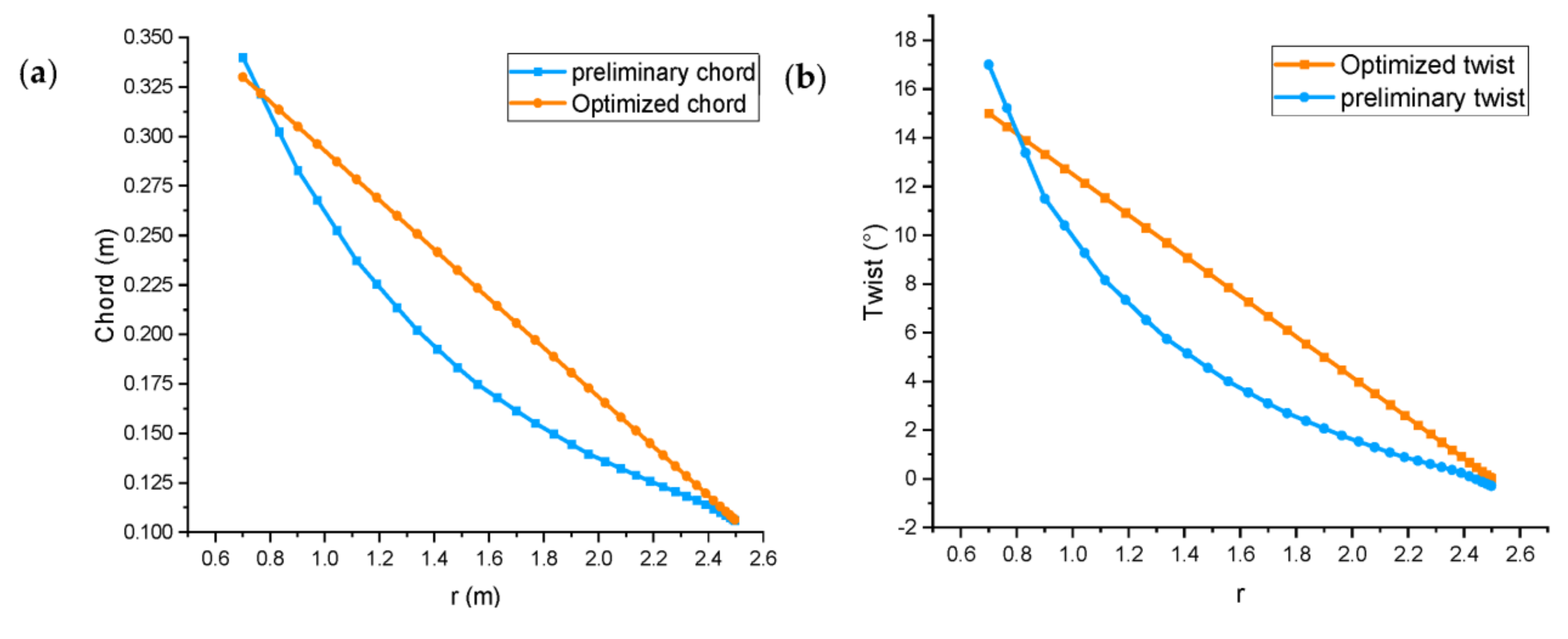
2.1. Wind Turbine Blade Design
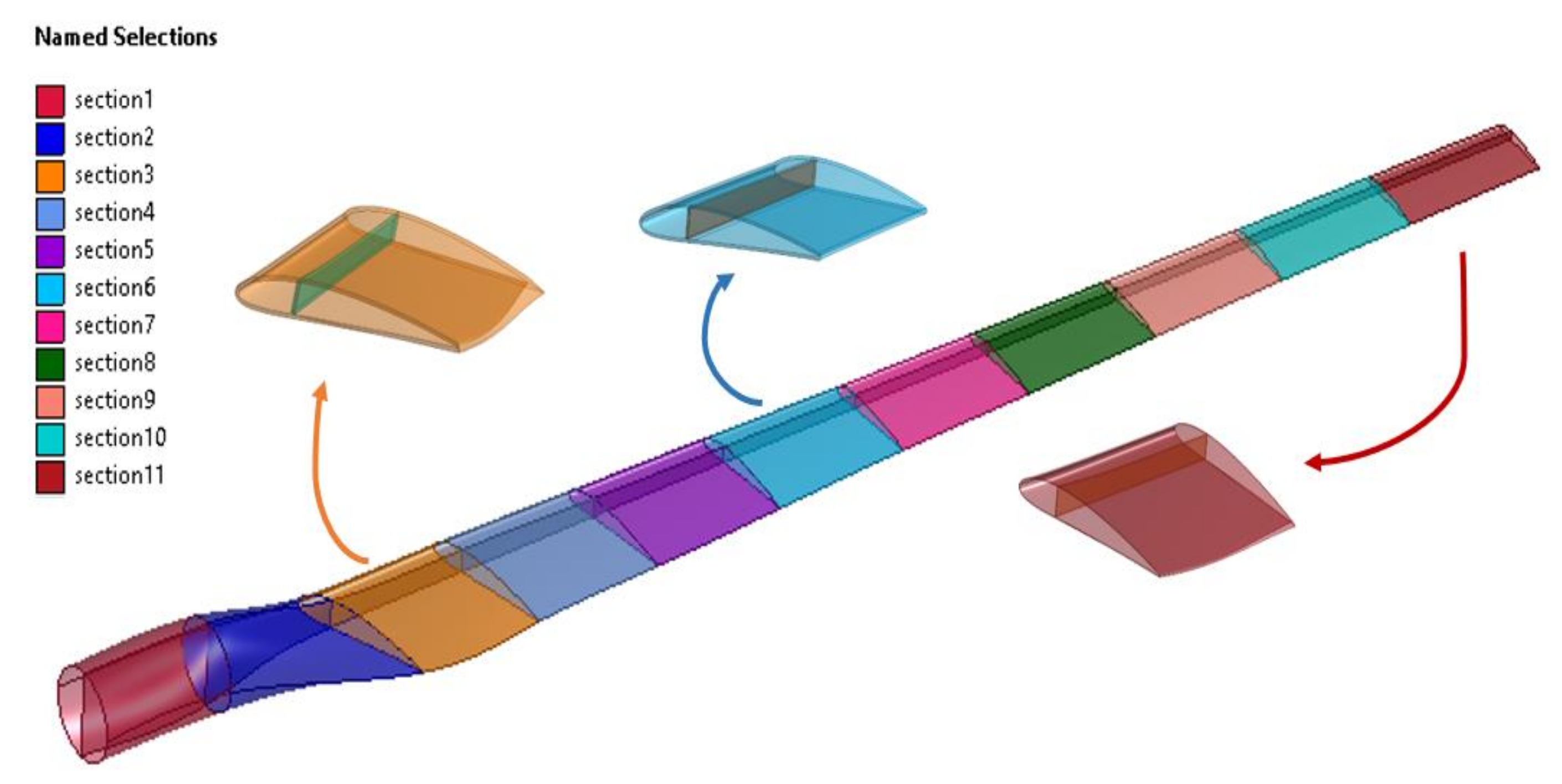
2.2. Blade’s Material and Lay-Up Sequence
2.3. Finite Element Analysis of Steady-State Problem
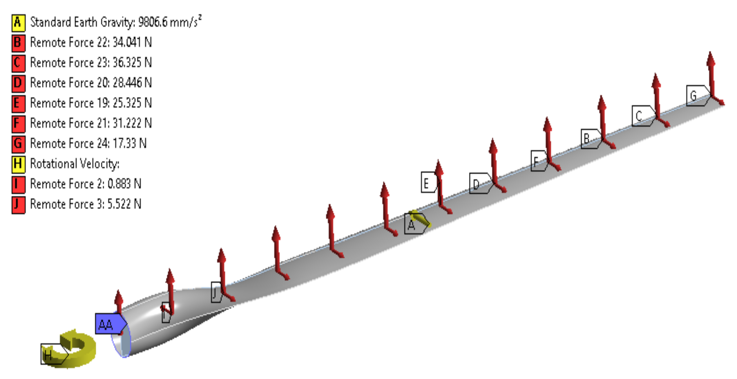
2.4. Boundary Conditions
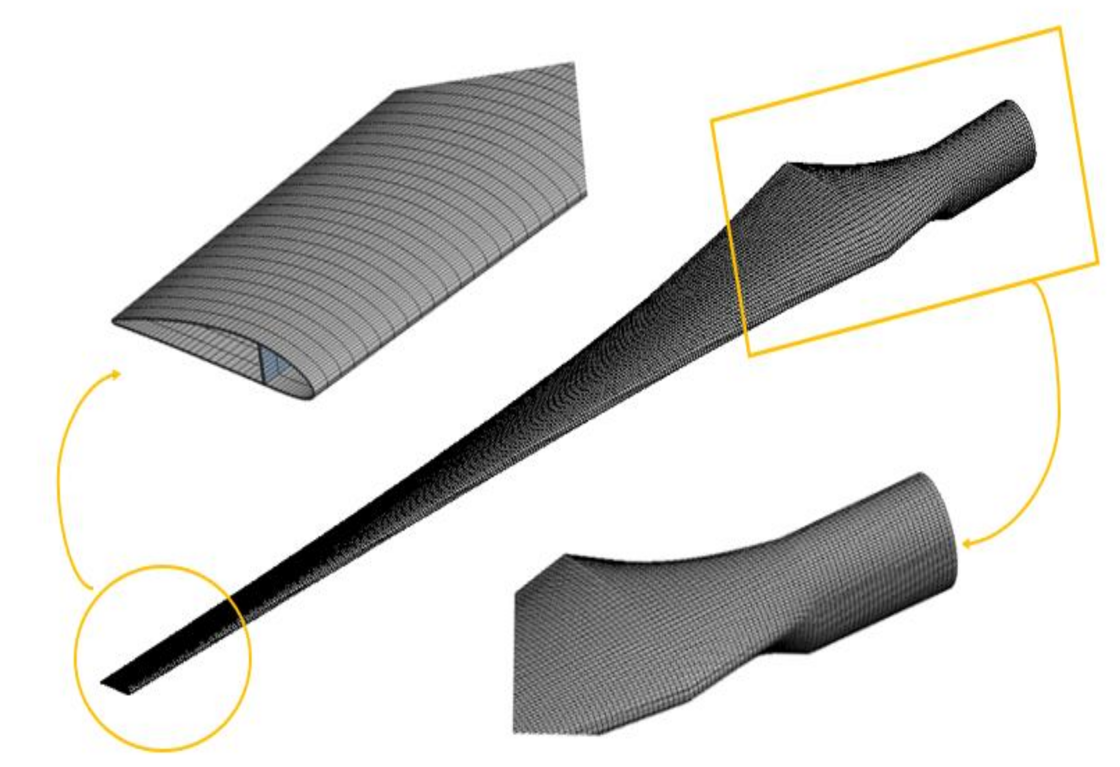
2.5. FE Modeling of Wind Blade
2.6. The FE Formulation
3. Results and Discussions
4. Conclusions and Future Work
Author Contributions
Funding
Institutional Review Board Statement
Informed Consent Statement
Data Availability Statement
Acknowledgments
Conflicts of Interest
Nomenclature
| c | Chord length |
| Power coefficient | |
| Reynolds number | |
| Relative velocity | |
| Design wind speed | |
| r | Local radius |
| R | Wind turbine radius |
| Design lift coefficient | |
| Number of blades | |
| Tangential load | |
| Normal load | |
| Load vector | |
| Displacement vectors | |
| [K] | Stiffness matrix |
| [M] | Mass matrix |
| Acceleration | |
| [A] | dynamic matrix |
| [I] | Identity matrix |
| X | eigenvector |
| Young’s modulus | |
| Greek symbols | |
| Twist angel | |
| Reynolds or turbulent stress | |
| viscosity | |
| angular natural frequency | |
| Air density | |
| Optimal angel of attack | |
| Local speed ratio | |
| Design tip speed ratio | |
| Relative angle | |
| Rotational speed | |
| Superscripts | |
| WWEA | World wind energy association |
| GWEC | Global wind energy council |
| AEP | Annual energy production |
| FEM | Finite element method |
| UD | Unidirectional |
| BEM | blade element momentum |
| AoA | Angle of Attack |
| DOF | degrees of freedom |
| HAWT | Horizontal axis wind turbine |
| CFD | computational fluid dynamics |
References
- Rosato, M.A. Small Wind Turbines for Electricity and Irrigation: Design and Construction; CRC Press: New York, NY, USA, 2018. [Google Scholar]
- WWEA. World Wind Energy Association. Available online: https://wwindea.org/information-2/statistics-news/ (accessed on 24 March 2022).
- Rašuo, B.P.; Bengin, A.Č. Optimization of wind farm layout. FME Trans. 2010, 38, 107–114. [Google Scholar]
- Norouzi, N.; Bozorgian, A. A Wind-Thermal System Design Based on an Energetic and Exergetic Approch. Iran. J. Chem. Chem. Eng. 2022. [Google Scholar] [CrossRef]
- Win, S.Y.; Thianwiboon, M. Parametric optimization of NACA 4412 airfoil in ground effect using full factorial design of experiment. Eng. J. 2021, 25, 9–19. [Google Scholar]
- Mousavi, S.M.; Shafiei, N.; Dadvand, A. Numerical simulation of subsonic turbulent flow over NACA0012 airfoil: Evaluation of turbulence models. Sigma J. Eng. Nat. Sci. 2017, 35, 133–155. [Google Scholar]
- Garcia-Ribeiro, D.; Flores-Mezarina, J.A.; Bravo-Mosquera, P.D.; Cerón-Muñoz, H.D. Parametric CFD analysis of the taper ratio effects of a winglet on the performance of a Horizontal Axis Wind Turbine. Sustain. Energy Technol. Assess. 2021, 47, 101489. [Google Scholar] [CrossRef]
- Bai, C.-J.; Wang, W.-C. Review of computational and experimental approaches to analysis of aerodynamic performance in horizontal-axis wind turbines (HAWTs). Renew. Sustain. Energy Rev. 2016, 63, 506–519. [Google Scholar] [CrossRef]
- Maizi, M.; Mohamed, M.; Dizene, R.; Mihoubi, M. Noise reduction of a horizontal wind turbine using different blade shapes. Renew. Energy 2018, 117, 242–256. [Google Scholar] [CrossRef]
- Kaya, M.N.; Kose, F.; Ingham, D.; Ma, L.; Pourkashanian, M. Aerodynamic performance of a horizontal axis wind turbine with forward and backward swept blades. J. Wind. Eng. Ind. Aerodyn. 2018, 176, 166–173. [Google Scholar] [CrossRef] [Green Version]
- Parezanovic, V.; Rasuo, B.; Adzic, M. Design of airfoils for wind turbine blades. In Proceedings of the French-Serbian European Summer University: Renewable Energy Sources and Environment-Multidisciplinary Aspect, Vrnjacka Banja, Serbia, 17–24 October 2006. [Google Scholar]
- Song, F.; Ni, Y.; Tan, Z. Optimization design, modeling and dynamic analysis for composite wind turbine blade. Procedia Eng. 2011, 16, 369–375. [Google Scholar] [CrossRef] [Green Version]
- Lipian, M.; Czapski, P.; Obidowski, D. Fluid–structure interaction numerical analysis of a small, urban wind turbine blade. Energies 2020, 13, 1832. [Google Scholar] [CrossRef]
- Boudounit, H.; Tarfaoui, M.; Saifaoui, D.; Nachtane, M. Structural analysis of offshore wind turbine blades using finite element method. Wind Eng. 2020, 44, 168–180. [Google Scholar] [CrossRef]
- Wu, W.H.; Young, W.B. Structural analysis and design of the composite wind turbine blade. Appl. Compos. Mater. 2012, 19, 247–257. [Google Scholar] [CrossRef]
- Pourrajabian, A.; Afshar, P.A.N.; Ahmadizadeh, M.; Wood, D. Aero-structural design and optimization of a small wind turbine blade. Renew. Energy 2016, 87, 837–848. [Google Scholar] [CrossRef]
- Tüfekci, M.; Genel, Ö.E.; Tatar, A.; Tüfekci, E. Dynamic Analysis of Composite Wind Turbine Blades as Beams: An Analytical and Numerical Study. Vibration 2021, 4, 1–15. [Google Scholar] [CrossRef]
- Navadeh, N.; Goroshko, I.; Zhuk, Y.; Etminan Moghadam, F.; Soleiman Fallah, A. Finite Element Analysis of Wind Turbine Blade Vibrations. Vibration 2021, 4, 310–322. [Google Scholar] [CrossRef]
- Lagdani, O.; Tarfaoui, M.; Nachtane, M.; Trihi, M.; Laaouidi, H. Modal analysis of an iced offshore composite wind turbine blade. Wind Eng. 2022, 46, 134–149. [Google Scholar] [CrossRef]
- Puterbaugh, M.; Beyene, A. Parametric dependence of a morphing wind turbine blade on material elasticity. Energy 2011, 36, 466–474. [Google Scholar] [CrossRef]
- Alkhabbaz, A.; Yang, H.-S.; Weerakoon, A.S.; Lee, Y.-H. A novel linearization approach of chord and twist angle distribution for 10 kW horizontal axis wind turbine. Renew. Energy 2021, 178, 1398–1420. [Google Scholar] [CrossRef]
- Gupta, M.K.; Subbarao, P. Design and Performance Analysis of Hydrokinetic Turbine with Aerodynamic Stall Model. In Advances in Thermofluids and Renewable Energy; Springer: Singapore, 2021; pp. 221–231. [Google Scholar]
- Marten, D.; Wendler, J. QBlade Guidelines v0.6; TU Berlin: Berlin, Germany, 2013. [Google Scholar]
- Zhou, S.; Wu, X. Fatigue life prediction of composite laminates by fatigue master curves. J. Mater. Res. 2019, 8, 6094–6105. [Google Scholar] [CrossRef]
- Gao, X.; Yuan, L.; Fu, Y.; Yao, X.; Yang, H. Prediction of mechanical properties on 3D braided composites with void defects. Compos. Part B Eng. 2020, 197, 108164. [Google Scholar] [CrossRef]
- Pagano, A. Aerodynamic Analyses of Tiltrotor Morphing Blades. In Morphing Wing Technologies; Elsevier: Amsterdam, The Netherlands, 2018; pp. 799–839. [Google Scholar] [CrossRef]
- Zuheir, S.; Abdullah, O.I.; Al-Maliki, M. Stress and vibration analyses of the wind turbine blade (A NREL 5MW). J. Mech. Eng. Res. Dev. 2019, 42, 14–19. [Google Scholar] [CrossRef]
- Garinis, D.; Dinulović, M.; Rašuo, B. Dynamic analysis of modified composite helicopter blade. FME Trans. 2012, 40, 63–68. [Google Scholar]
- Abdullah, O.I. A finite element analysis for the damaged rotating composite blade. Al-Khwarizmi Eng. J. 2011, 7, 56–75. [Google Scholar]
- Miau, J.-J.; Li, S.-R.; Tsai, Z.-X.; Van Phung, M.; Lin, S.-Y. On the aerodynamic flow around a cyclist model at the hoods position. J. Vis. 2019, 23, 35–47. [Google Scholar] [CrossRef] [Green Version]
- Abdullah, O. Vibration analysis of rotating pre-twisted cantilever plate by using the finite element method. J. Eng. 2009, 15, 3492–3505. [Google Scholar]


| Design Parameter | Value | Unit |
|---|---|---|
| Rated power | 5 | [kW] |
| Design Wind speed | 10.5 | m/s] |
| Number of blades | 3 | [-] |
| Design tip speed ratio | 6 | [-] |
| Design angle of attack | 6 | [°] |
| Rotor radius | 2.5 | [m] |
| Design rotational speed | 240 | [rpm] |
| Density of air | 1.22 | [kg/m3] |
| Airfoil type | NACA4412 | [-] |
| Material | E-Glass/Epoxy [24] | Carbon/Epoxy [24] | Braided Composite [24,25] |
|---|---|---|---|
| (GPa) | 48.7 | 136.7 | 62.8 |
| (GPa) | 16.8 | 8.2 | 62.8 |
| (GPa) | 5.83 | 4.45 | 9.68 |
| (GPa) | 6 | 2.91 | 7.97 |
| 0.28 | 0.29 | 0.33 | |
| 0.20 | 0.42 | 0.40 | |
| (MPa) | 1170 | 1604 | 460 |
| (MPa) | 977 | 1305 | 420.4 |
| (MPa) | 30.5 | 40.5 | 526.2 |
| (MPa) | 114 | 239.7 | 420.4 |
| (kg/m3) | 2000 | 1518 | 1800 |
| Section Name | Location (m) | Shell Layup | Thickness (m) | Shear Web Lay-Up | Thickness (m) |
|---|---|---|---|---|---|
| 1 | 0.200–0.400 | [(±45)3/08/(±45)]s | 0.0064 | [(±45)3/09/(±45)]s | 0.0070 |
| 2 | 0.400–0.600 | [(±45)3/07/(±45)]s | 0.0058 | [(±45)3/08/(±45)]s | 0.0064 |
| 3 | 0.600–0.811 | [(±45)3/06/(±45)]s | 0.0052 | [(±45)3/07/(±45)]s | 0.0058 |
| 4 | 0.811–1.022 | [(±45)2/06/(±45)]s | 0.0048 | [(±45)3/06/(±45)]s | 0.0052 |
| 5 | 1.022–1.233 | [(±45)2/05/(±45)]s | 0.0042 | [(±45)2/06/(±45)]s | 0.0048 |
| 6 | 1.233–1.444 | [(±45)2/04/(±45)]s | 0.0036 | [(±45)2/05/(±45)]s | 0.0042 |
| 7 | 1.444–1.655 | [(±45)2/03/(±45)]s | 0.0030 | [(±45)2/04/(±45)]s | 0.0036 |
| 8 | 1.655–1.866 | [(±45)2/02/(±45)]s | 0.0024 | [(±45)2/03/(±45)]s | 0.0030 |
| 9 | 1.866–2.077 | [(±45)/02/(±45)]s | 0.0020 | [(±45)2/02/(±45)]s | 0.0024 |
| 10 | 2.077–2.288 | [(±45)/01/(±45)]s | 0.0014 | [(±45)/02/(±45)]s | 0.0020 |
| 11 | 2.288–2.500 | [(±45)/01/(±45)] | 0.0007 | [(±45)/01/(±45)]s | 0.0014 |
| 0.200 | 0.200 | −1.535 | 2.930 |
| 0.400 | 0.200 | −4.415 | 8.825 |
| 0.600 | 0.200 | 27.610 | 57.455 |
| 0.811 | 0.211 | 38.052 | 81.014 |
| 1.022 | 0.211 | 36.047 | 93.246 |
| 1.233 | 0.211 | 35.260 | 106.279 |
| 1.444 | 0.211 | 34.701 | 120.023 |
| 1.655 | 0.211 | 34.492 | 134.815 |
| 1.866 | 0.211 | 33.881 | 147.971 |
| 2.077 | 0.211 | 32.781 | 161.331 |
| 2.288 | 0.211 | 29.654 | 172.156 |
| 2.500 | 0.212 | 9.8160 | 81.7452 |
| Mesh Segments | No. Nodes | No. Elements | Max. Total Deflection [mm] | Difference |
|---|---|---|---|---|
| 1 | 19,824 | 3694 | 18.392 | - |
| 2 | 26,722 | 7431 | 18.371 | −0.021 |
| 3 | 34,624 | 11,385 | 18.365 | −0.006 |
| 4 | 45,857 | 15,124 | 18.361 | −0.004 |
| 5 | 74,154 | 24,475 | 18.356 | −0.005 |
| 6 | 108,789 | 35,970 | 18.354 | −0.002 |
| 7 | 225,602 | 75,053 | 18.358 | 0.004 |
| E-Glass/Epoxy | Braided Composite | Carbon/Epoxy | |||||||
|---|---|---|---|---|---|---|---|---|---|
| QBlade | ANSYS | Difference % | QBlade | ANSYS | Difference % | QBlade | ANSYS | Difference % | |
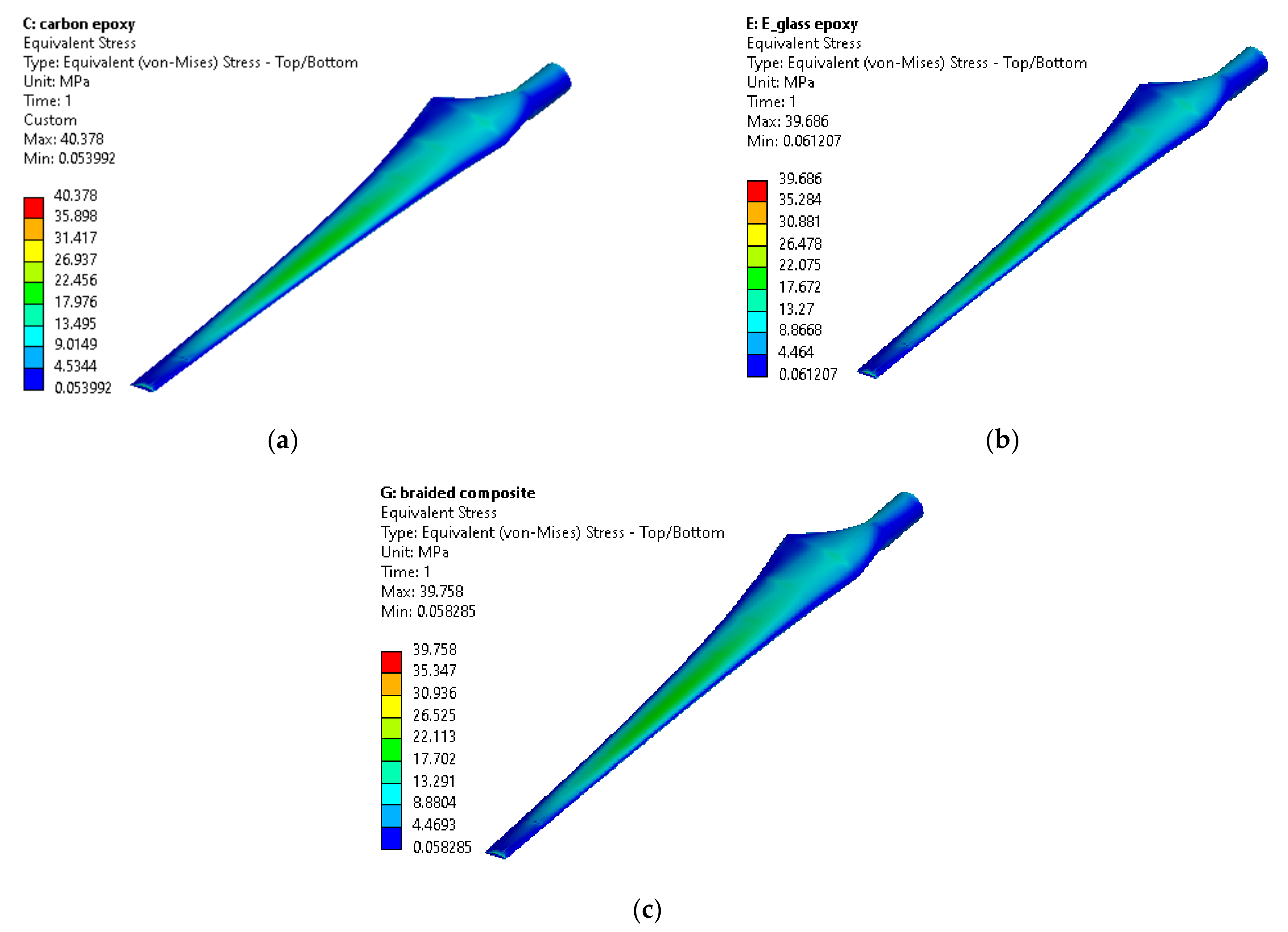
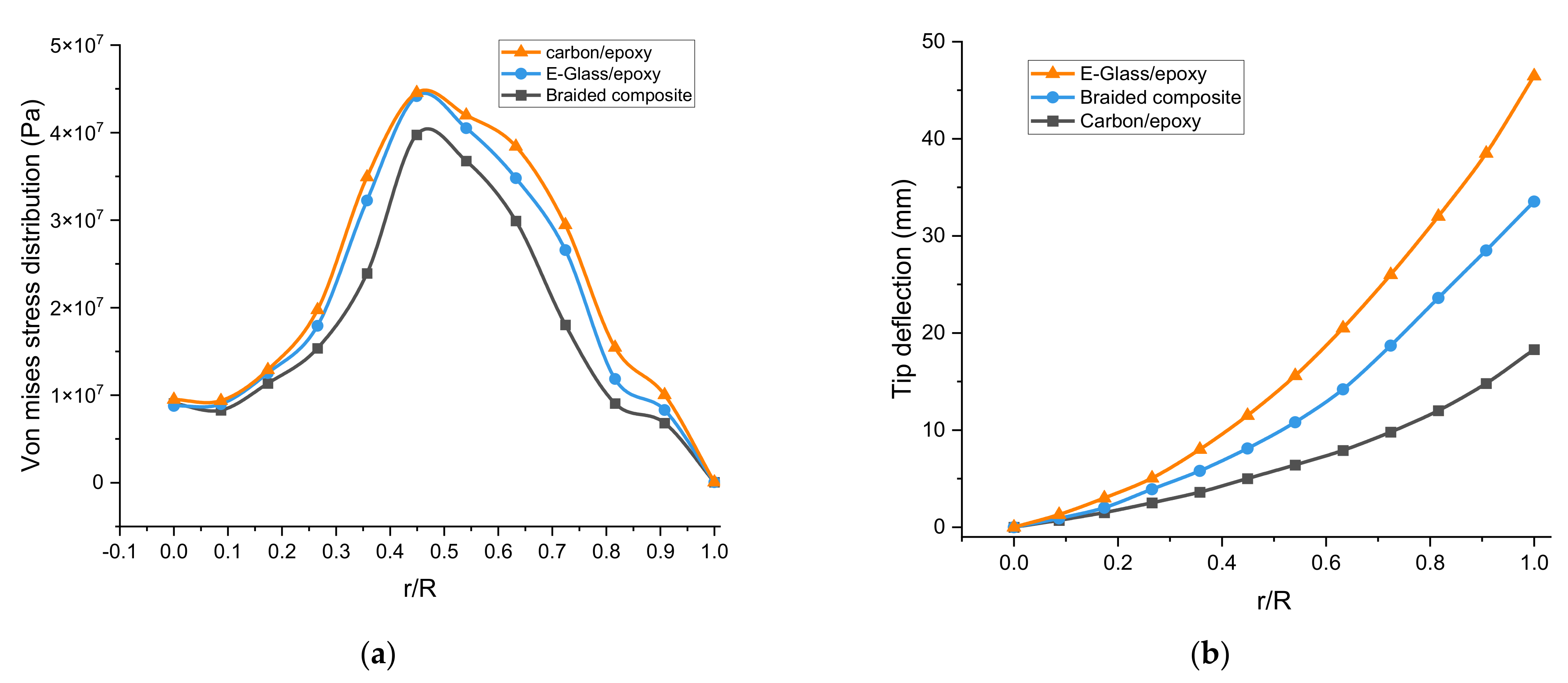
| Von mises stress [MPa] | 38.51 | 39.68 | 2.94 | 39.20 | 39.75 | 1.38 | 39.96 | 40.37 | 1.015 |
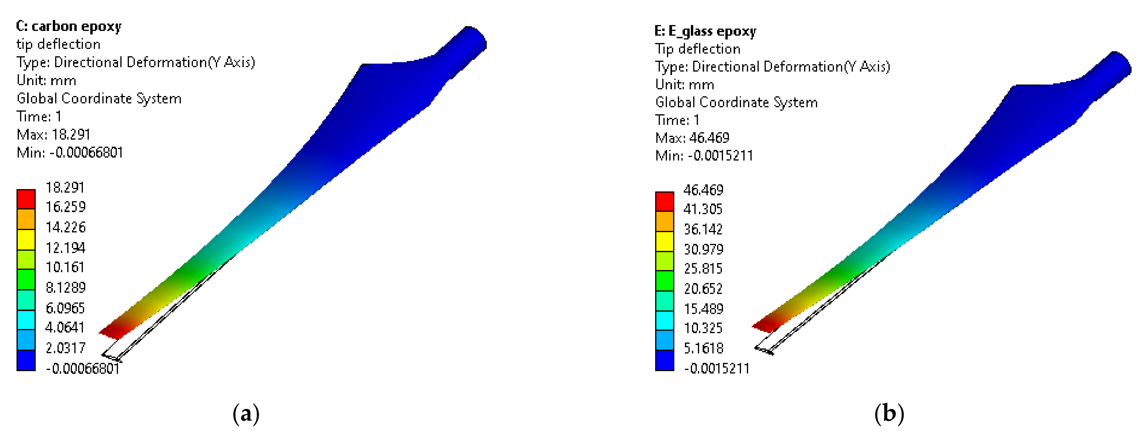
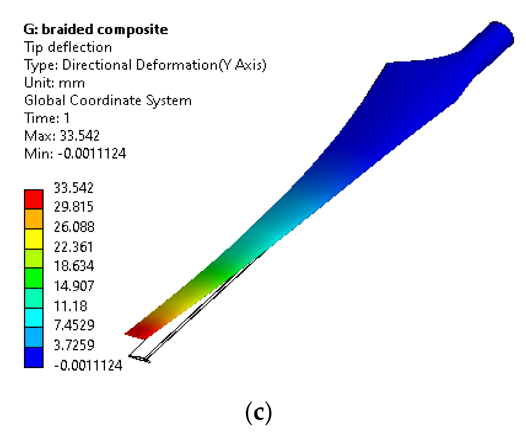
| Tip deflection[mm] | 43.20 | 46.46 | 7.016 | 29.32 | 33.54 | 6.61 | 16.86 | 18.29 | 7.81 |
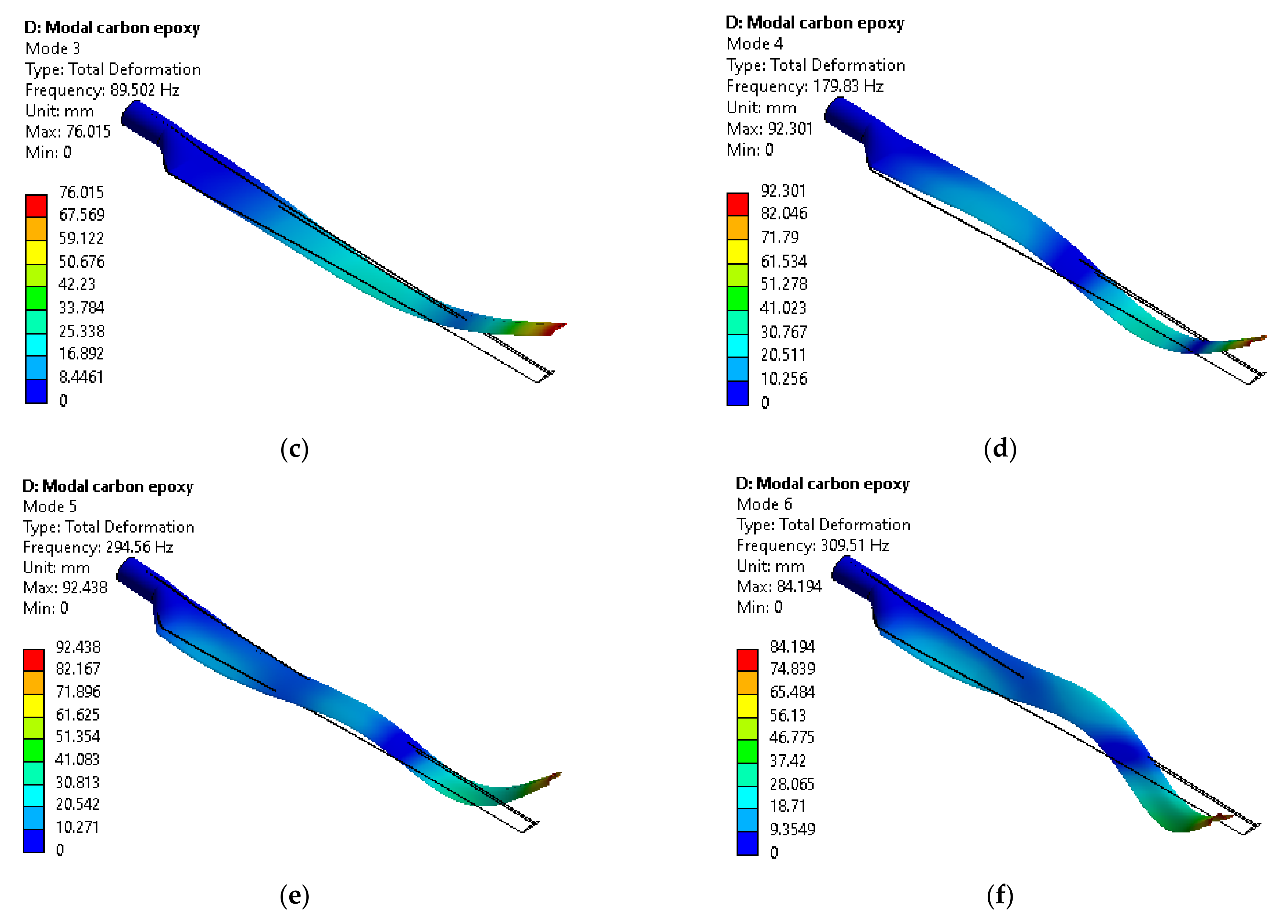
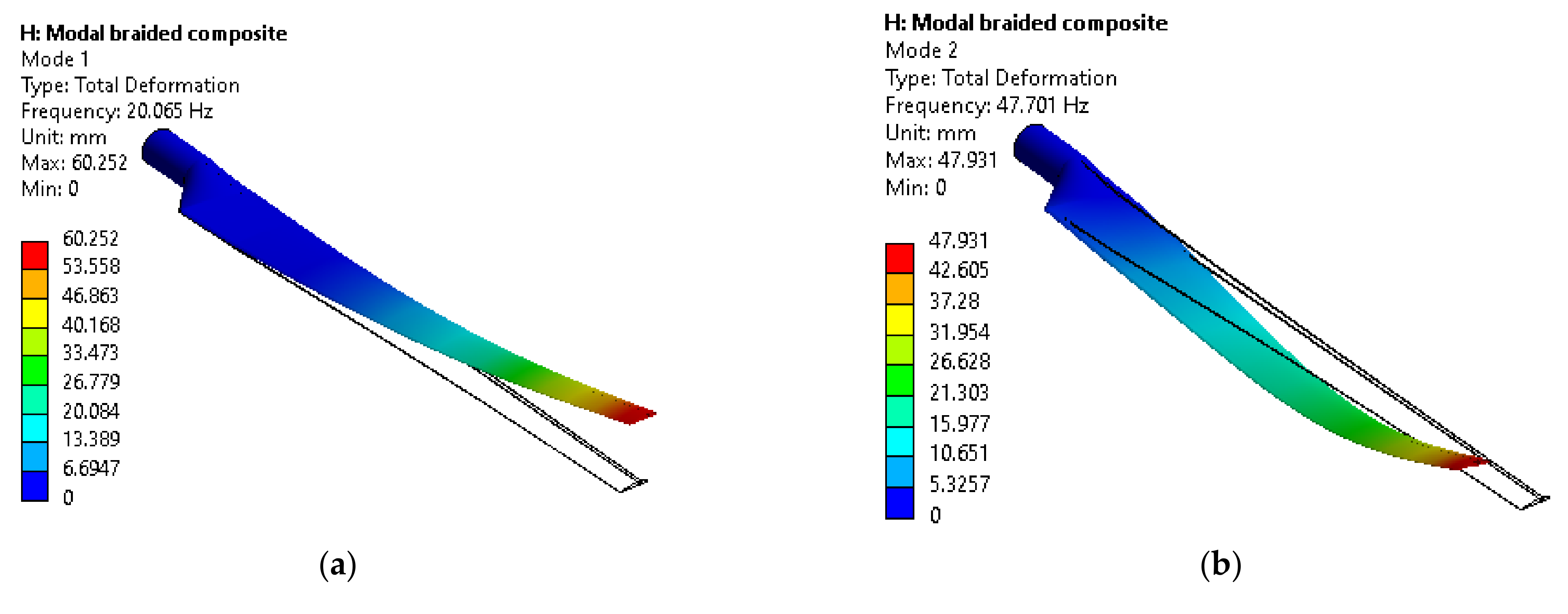
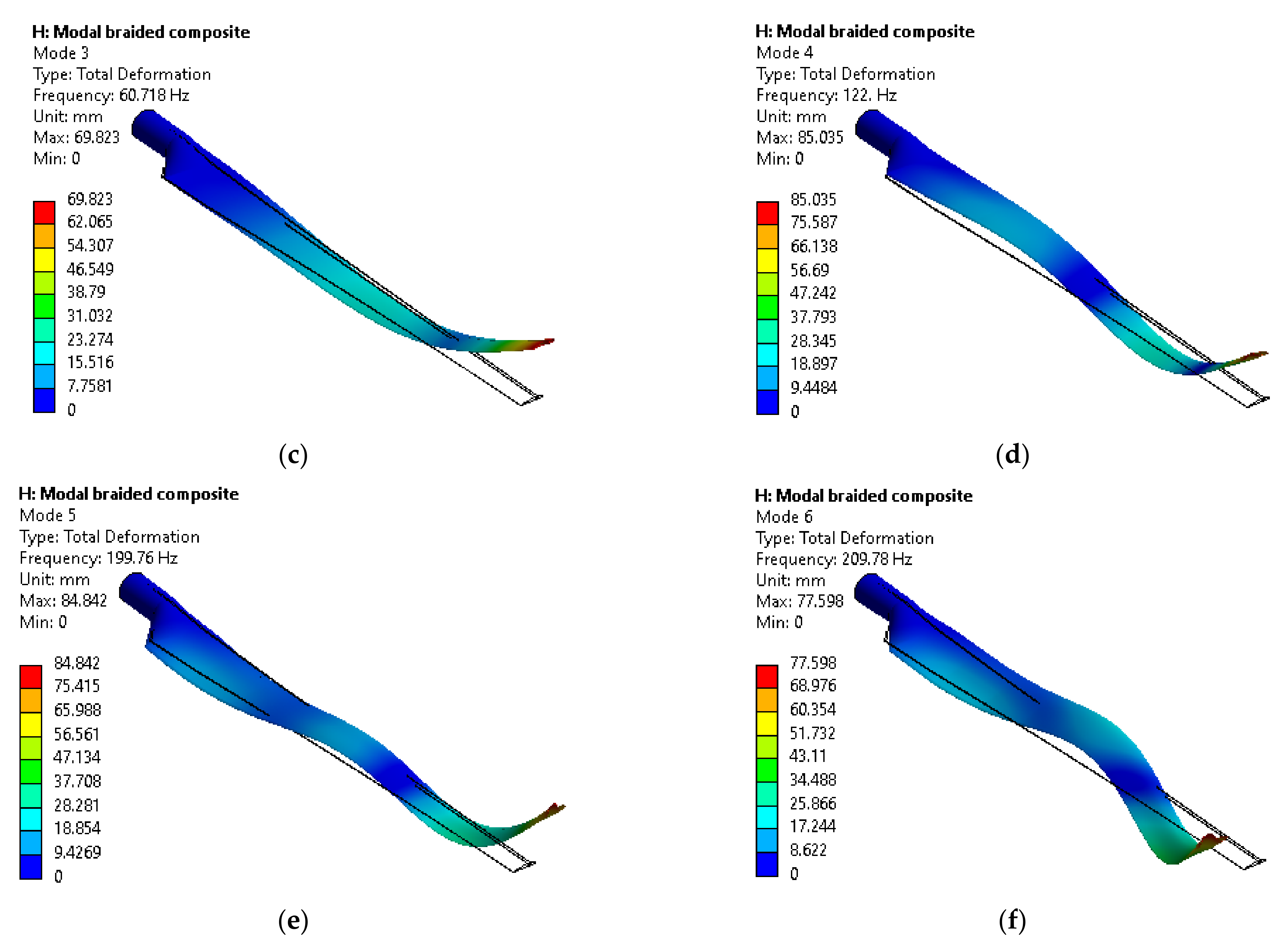
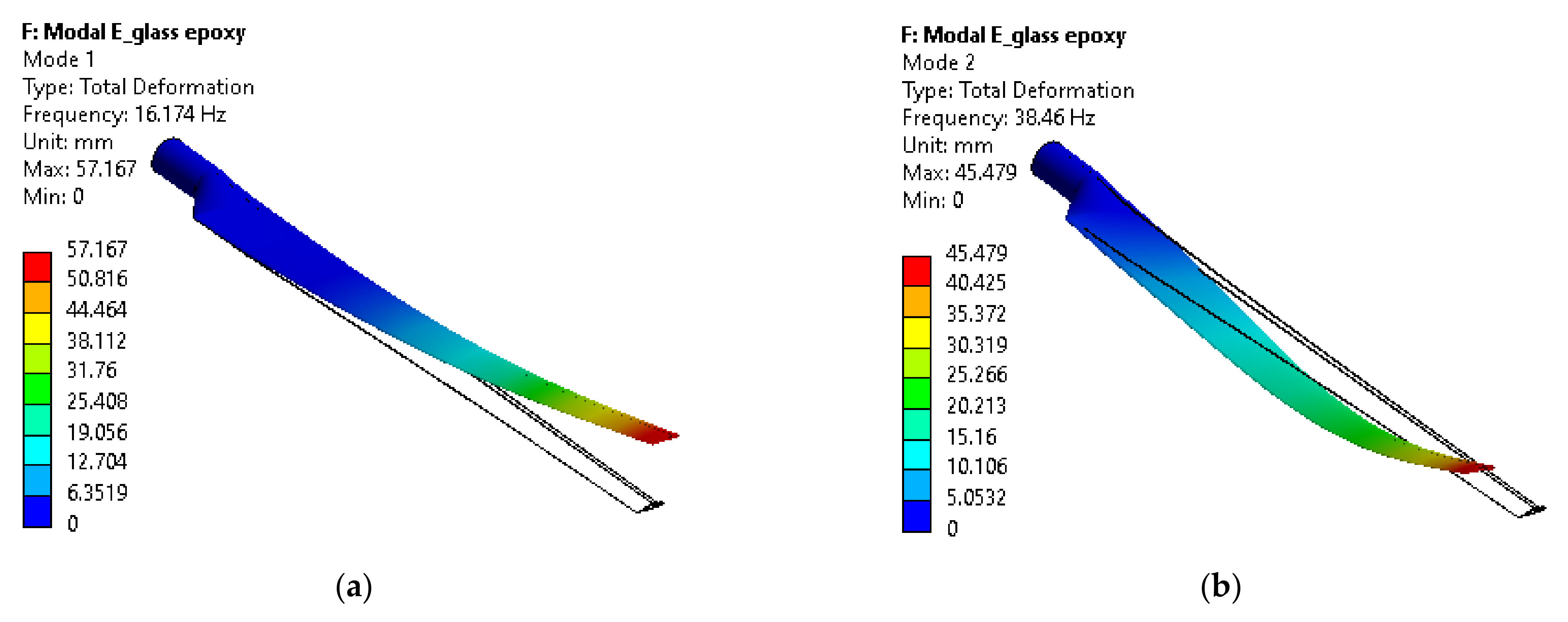
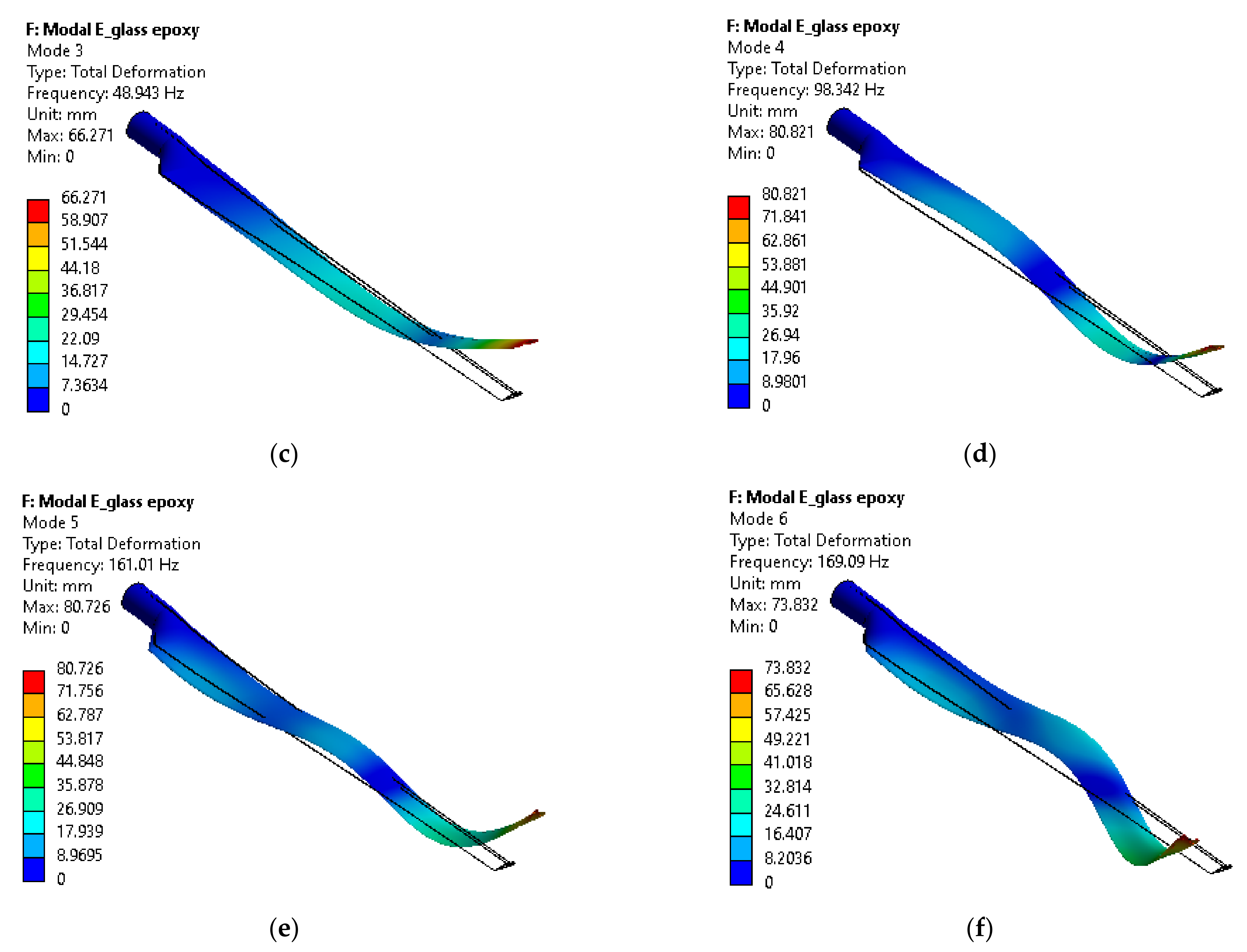
| Mode | E-glass/Epoxy | Braided Composite | Carbon/Epoxy | ||||||
|---|---|---|---|---|---|---|---|---|---|
| QBlade | ANSYS | Difference % | QBlade | ANSYS | Difference % | QBlade | ANSYS | Difference % | |
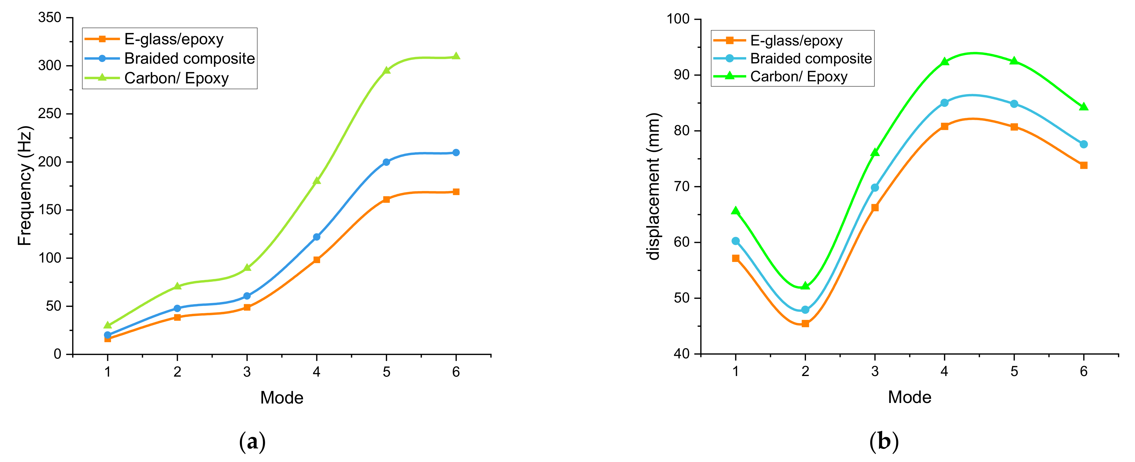
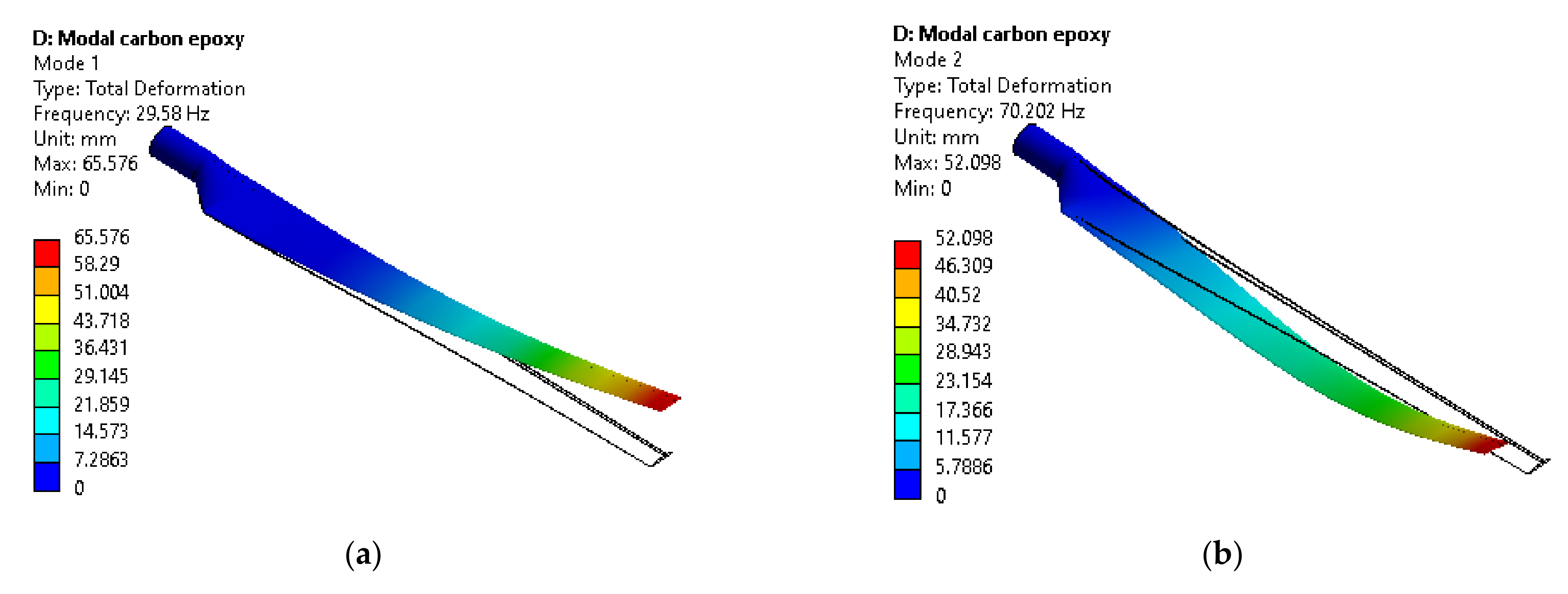
| 1 | 15.13 | 16.17 | 6.43 | 19.80 | 20.06 | 1.30 | 28.29 | 29.58 | 4.36 |
| 2 | 36.19 | 38.46 | 5.90 | 48.32 | 47.70 | 1.30 | 74.11 | 70.20 | 5.57 |
| 3 | 45.39 | 48.94 | 7.25 | 63.41 | 60.71 | 4.45 | 92.20 | 89.50 | 3.02 |
| 4 | 99.56 | 98.34 | 1.24 | 130.59 | 122 | 7.04 | 185.14 | 179.83 | 2.95 |
| 5 | 165.82 | 161.01 | 2.99 | 196.43 | 199.76 | 1.67 | 289.23 | 294.56 | 1.81 |
| 6 | 172.93 | 169.09 | 2.27 | 221.15 | 209.78 | 5.42 | 315.67 | 309.51 | 1.99 |
Disclaimer/Publisher’s Note: The statements, opinions and data contained in all publications are solely those of the individual author(s) and contributor(s) and not of MDPI and/or the editor(s). MDPI and/or the editor(s) disclaim responsibility for any injury to people or property resulting from any ideas, methods, instructions or products referred to in the content. |
© 2023 by the authors. Licensee MDPI, Basel, Switzerland. This article is an open access article distributed under the terms and conditions of the Creative Commons Attribution (CC BY) license (https://creativecommons.org/licenses/by/4.0/).
Share and Cite
Deghoum, K.; Gherbi, M.T.; Sultan, H.S.; Jameel Al-Tamimi, A.N.; Abed, A.M.; Abdullah, O.I.; Mechakra, H.; Boukhari, A. Optimization of Small Horizontal Axis Wind Turbines Based on Aerodynamic, Steady-State, and Dynamic Analyses. Appl. Syst. Innov. 2023, 6, 33. https://doi.org/10.3390/asi6020033
Deghoum K, Gherbi MT, Sultan HS, Jameel Al-Tamimi AN, Abed AM, Abdullah OI, Mechakra H, Boukhari A. Optimization of Small Horizontal Axis Wind Turbines Based on Aerodynamic, Steady-State, and Dynamic Analyses. Applied System Innovation. 2023; 6(2):33. https://doi.org/10.3390/asi6020033
Chicago/Turabian StyleDeghoum, Khalil, Mohammed Taher Gherbi, Hakim S. Sultan, Adnan N. Jameel Al-Tamimi, Azher M. Abed, Oday Ibraheem Abdullah, Hamza Mechakra, and Ali Boukhari. 2023. "Optimization of Small Horizontal Axis Wind Turbines Based on Aerodynamic, Steady-State, and Dynamic Analyses" Applied System Innovation 6, no. 2: 33. https://doi.org/10.3390/asi6020033