A Data-Driven Constitutive Model for 3D Lattice-Structured Material Utilising an Artificial Neural Network


1
Mechanical Engineering Group, School of Engineering, University of Kent, Canterbury CT2 7NT, UK
2
School of Mechanical Engineering Sciences, University of Surrey, Guildford GU2 7XH, UK
*
Author to whom correspondence should be addressed.
Appl. Mech. 2024, 5(1), 212-232; https://doi.org/10.3390/applmech5010014
Submission received: 10 February 2024
/
Revised: 26 February 2024
/
Accepted: 14 March 2024
/
Published: 20 March 2024
Abstract
:A new data-driven continuum model based on an artificial neural network is developed in this study for a new three-dimensional lattice-structured material design. The model has the capability to capture and predict the nonlinear elastic behaviour of the specific lattice-structured material in the three-dimensional continuum description after being trained through the appropriate dataset. The essential data as the input ingredients of the data-driven model are provided through a hybrid method including experimental and unit-cell level finite element simulations under comprehensive loading scenarios including uniaxial, biaxial, volumetric, and pure shear loading. Furthermore, the lattice-structured samples are also fabricated using SLA additive manufacturing technology and the experimental measurements are performed and used for validation of the model. This then illustrates that the current model/methodology is a robust and powerful numerical tool to conduct the homogenization in complex simulation cases and could be used to accelerate the analysis and optimization during the design process of new lattice-structured materials. The model could also easily be used for other engineered materials by updating the dataset and re-training the ANN model with new data.
1. Introduction
A lattice-structured material is purposely designed to have a repeating, interconnected network of struts or beams arranged in either two-dimensional (2D) or three-dimensional (3D) space. This combination of struts and beams are linked at nodes, forming unit cells that describe the overall geometry and mechanical behaviour of the material. Such materials have properties that depend on (i) the configuration of the unit cell, (ii) the way unit cells are interlinked together, and (iii) the parent materials. Depending on the manufacturing techniques, the parent material could be any thermoplastic/thermoset polymers, metals, ceramics, and composites. As a result, lattice-structured materials provide a diverse combination of tailorable thermos-mechanical properties that make them an attractive case of research in recent years. These outstanding properties include tailorable mechanical strength and stiffness [1,2], a lightweight property [3,4], excellent energy absorption ability [5,6] and impact absorption [7,8]. Therefore, lattice-structured materials have been nominated for several potential industrial applications within the aerospace, personal protective equipment, sports equipment, packaging, military and defence, and medical equipment sectors [9,10,11,12]. This makes lattice-structured material an interesting and promising area of research for material scientists and engineers, as well as product designers.
Despite the interesting aspects of lattice-structured materials, there are specific challenges that have postponed the integration of these materials in real-world industrial applications. Some of these challenging aspects are related to (i) the complex design process, (ii) limited manufacturing techniques, (iii) a lack of understanding of the mechanical behaviour, and (iv) the lack of an appropriate analytical framework to perform cost-effective simulations with these materials. Whilst the recent progress in additive manufacturing technologies facilitates the fabrication of novel lattice-structured materials and exploration of their behaviour through changing their geometric structure, there is still an essential demand for a robust analytical tool that could incorporate the effect of structural change to the macroscale performance of the material. This computational framework is also a crucial step in the product design process with engineered materials as the classical experimentally based trial-and-error methods are usually expensive and slow to operate. Furthermore, this desired computational framework could be used to tune and/or optimize the performance of the design before proceeding with the fabrication and advertising of the product.
Presenting an appropriate constitutive material model for any specific material plays a key role in developing an accurate and robust computational framework, which is essential for the product design process with novel materials. The classical approach to driving a continuum model for a material is to develop a phenomenological model to represent the physical behaviour of the material. Then, the material parameters in the phenomenological model are fitted according to the experimental data. A data-driven material model, on the other hand, is a recent approach of developing the continuum model of materials which is directly based on analysis of data. Therefore, a data-driven material model presents the relationships between the deformation and loads of a material without specifying one phenomenological equation. There are many advantages of using data-driven material models in comparison to classical approaches. For example, the data-driven approach eliminates the need to drive a phenomenological model for the physical behaviour of material and therefore, this could increase the accuracy of the model. Secondly, this approach is suitable for the material design and optimization process as it accelerates the computational trial-and-error design approach. Thirdly, it is possible to consider the probability distribution of the input data in this approach.
There are different methodologies presented in the literature to develop a data-driven material model for different types of problems. Kirchdoerfer and Ortiz [13] and Stainier et al. [14] developed a constitutive model-free approach that considers the conservation laws. Therefore, the minimization process assigns the solution to each material point that satisfies the conservation law and is the closest to the experimental dataset. On the other hand, Ibanez et al. present a new manifold learning methodology to develop correction to the current popular constitutive models (e.g., linear elasticity, nonlinear elasticity and plasticity) by minimizing the error [15,16]. Furthermore, there are multiple efforts to employ neural network algorithms and machine learning approaches to train a relationship between prescribed deformation and three-dimensional stress. For example, Huang et al. developed a machine learning approach for hyperelastic and plastic materials based on a Feedforward Neural network and training the model offline. They then differentiated the stress–strain trained model and calculated the tangent matrix for finite element implementation [17]. Bessa et al. also developed a Bayesian machine learning method to explore a material design approach for a specific three-dimensional metamaterial. The design space data was generated by finite element simulations and the trained machine learning model was used to choose the appropriate geometry, based material, and manufacturing method to achieve a target property [18].
Constitutive models that are based on artificial neural networks (ANNs) are among the most extensively used ML algorithms in exploring the mechanical behaviour of materials due to their exceptional prediction performance [19]. Nevertheless, the model was trained using a limited dataset that may not adequately capture the range of diversity and complexity in the behaviour of the material. To design the metamaterial structure with high-energy observation capability, an ANN constitutive model with a genetic algorithm is proposed to predict the mechanical behaviour of materials [20]. Although the ANN model demonstrates superior performance on the training data, the accuracy performance is not great on validation data. Moreover, the ANN constitutive model used in [21] accurately predicted the effective behaviour of the triangular lattice structures. However, it is important to note that the training data lack representation of diverse 3D loading case studies. In [22,23], a neural network-based constitutive model was designed that accurately represents the mechanical behaviour of lattice-structured over different loading tests such as uniaxial, biaxial, volumetric, and shear. A similar NN-based constitutive model was designed to study the behaviour of hyperelastic material over different loading tests [24]. However, in all the above-mentioned works the full dataset was developed through purely micro-scale simulation, with no experimental validation or hybrid data generation.
Considering the recent progress in this field and the new data-driven material models for mechanical metamaterials, we could conclude that to the best of our knowledge, various models work well under different situations. However, there are still significant gaps in (i) the data generation process, (ii) the predictability of the model beyond the training data, (iii) stability, and (iv) the ability to generalise the model to the wider lattice-structured material design. Therefore, in the current study, we focus on developing a new robust ANN-based material model to accurately predict and represent the three-dimensional mechanical behaviour of a specifically designed lattice-structured material, with the ability to be generalised into a wider group of lattice designs. The training dataset is prepared by a hybrid method, including employing 3D finite element simulations on the unit cell level for general loading scenarios, as well as physical experiments for uniaxial conditions. The proposed constitutive model undergoes experimental validation by conducting uniaxial compression tests, and finite element simulation on a full lattice structure model and the results were found to be in excellent agreement under various loading scenarios. Finally, to demonstrate the generalizability of the model or our model’s capability to be extended beyond the original training context to effectively model other lattice-structured materials, a case study is performed by changing the parent material into a compliant hyperelastic material and relevant experimental measurements, unit cell and full level finite element simulations, and validations are provided in this study to support the context.
The current work is organised as follows: The methodology of lattice-structure material design, data collection process, and experimental set-up is presented in Section 2. In Section 3, the proposed ANN-based constitutive model for the lattice-structured material is described. The validation results and the specific case study are presented in Section 4. Finally, Section 5 contains the concluding remarks.
2. Data Collection Method
The data collection methodology is an important systematic aspect of our research process to collect data for our designed lattice-structured material. Our designed unit cells, which integrate two distinct unit cells, were carefully modelled to make a novel lattice-structured material. Furthermore, extensive numerical investigations were undertaken by employing FEA to collect data on the unit cells subjected to various loading scenarios. In addition, the lattice-structured material was fabricated using additive manufacturing technology for experimental analysis and validation steps. Hence, the strategy adopted to collect data in this study is a hybrid as it involved the validation of the finite element model using experimental data.
2.1. Unit Cell Design of the Lattice-Structured Material
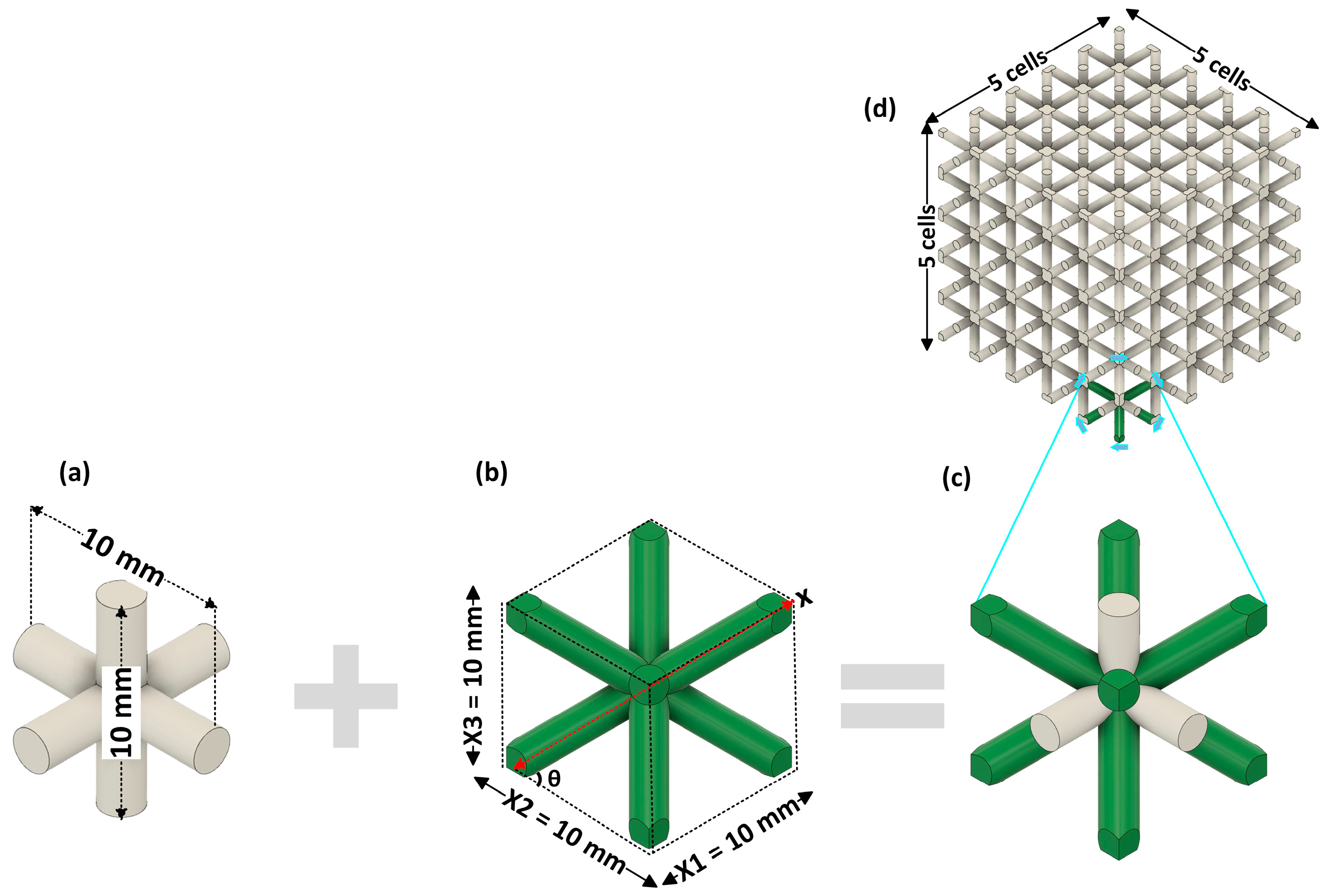
The lattice-structured material is composed of a three-dimensional network of the smallest repeating units, beams, or struts in a regular pattern that carries and distributes load through the network of beams and offers superior strength, lightweight, and energy absorption properties. Many different types of lattice-structured materials have been designed to acquire desired mechanical properties. Figure 1 depicts the combination of two unit cells to create a new structure unit cell for the purpose of our research. The unit cell depicted in Figure 1a, referred to as a grid [25], tri-axis cubic (TAC) [26], or centred-cubic (CC) unit cell [27,28], is merged with the body centred-cubic (BCC) unit cell, which is illustrated in Figure 1b, resulting in the formation of a new unit cell, shown in Figure 1c.
The motivation behind the concept of integrating two unit-cells into a single structure was the intent to combine the distinct mechanical benefits and behaviour of each unit cell into a novel unit cell. This method can be used to tailor the mechanical material properties to fulfil specific engineering applications and requirements. For example, the grid unit cell, which is defined by beams aligned particularly in two mutually perpendicular orientations, exhibited orthotropic features. Moreover, grid structures exhibit the greatest initial local force peaks and the greatest linear range stiffness [25]. Similarly, the BCC unit cell has received substantial attention in material studies due to its remarkable mechanical and energy-absorbing capabilities, high strength-to-weight ratio, and isotropic properties [29,30].
The unit cell’s dimensions are given as , , which represents the width, length and height of the unit cell, respectively. Due to the symmetrical nature of the unit cell’s design, all three dimensions, width, length, and height, were identical. The diameter of the strut was 2 mm and the diagonal length of the strut and the angle , as illustrated in Figure 1, could be calculated by and for the following unit cell. These design parameters are of the utmost importance for tailoring the mechanical properties of this lattice-structured material. By adjusting design parameters such as cell sizes, angle and strut length, and diameter of struts, we could generate gradient properties within the structure. Gradient properties offer the advantage of attaining diverse functionalities and optimising mechanical properties as discussed in detail in [31,32].
To perform experimental investigations in the next steps, the 3D lattice-structured specimen was made of arrays unit cells, having dimensions as illustrated in Figure 1d. The unit cells and lattice-structured material were designed by using the CAD module in ABAQUS 2022.
2.2. Data Acquisition through Unit Cell-Level Simulation
A robust data-driven method, as discussed in previous sections, needs a comprehensive dataset to capture all the physical behaviour of material under various loadings. Whilst collecting such a comprehensive dataset through purely experimental analysis is impossible, we used a hybrid method including both unit cell-level finite element simulation as well as physical experiments. Using the finite element method, and specifically the ABAQUS package in this study, it is possible to quantitate the behaviour of a unit cell of lattice-structured material under different loading scenarios such as uniaxial, shear, biaxial, and volumetric loading, etc. Although numerical simulations may provide valuable insights about material behaviour, experiment tests are performed to validate the accuracy of numerical simulations in real-world material modelling. Hence, numerical simulations enrich experimental data but cannot replace it.
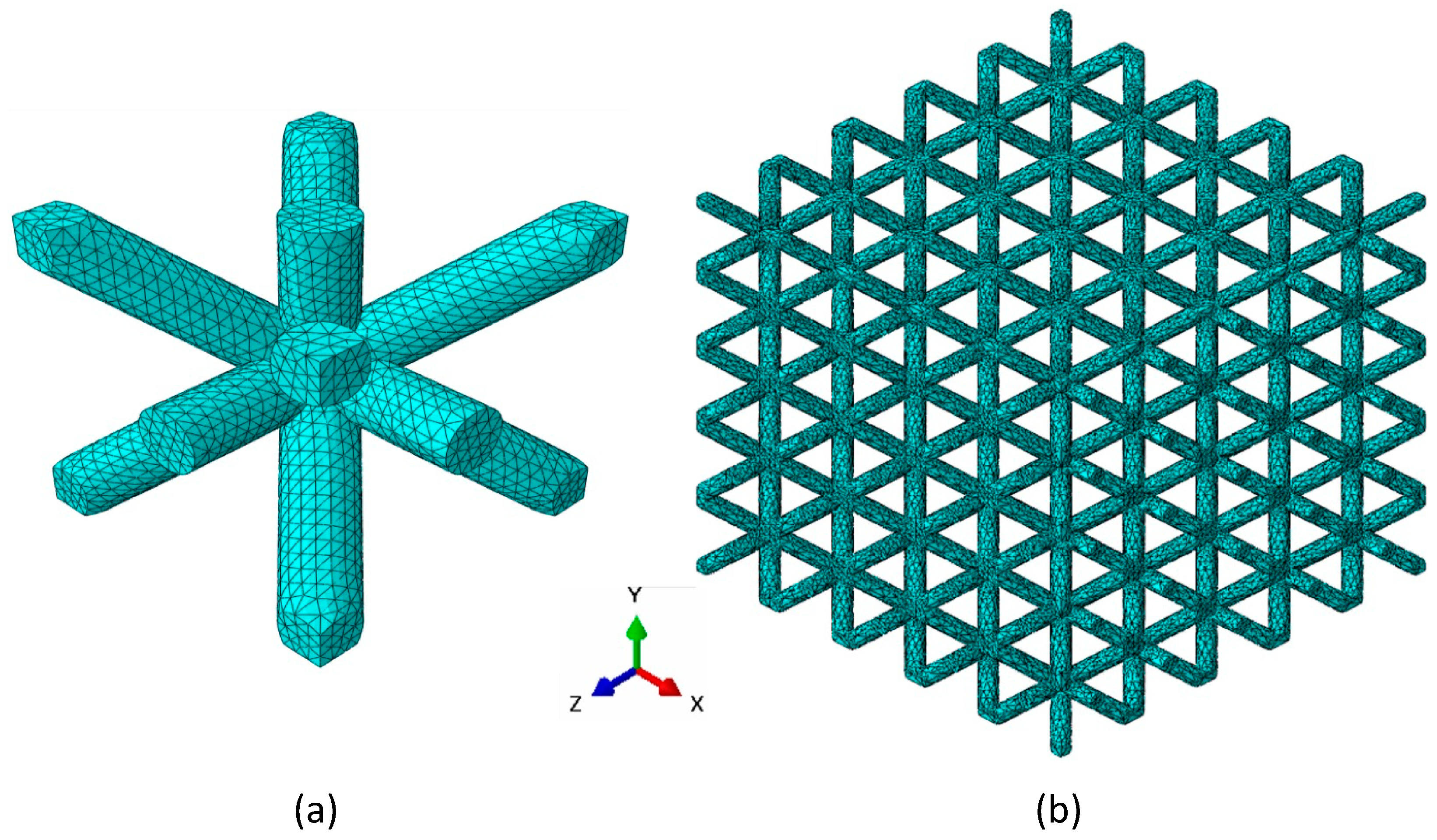
In order to carry out the numerical simulations, a commercially available solver called Abaqus 2022 [33] was utilised. The FEA was performed for both unit cells and the lattice-structured with a parent material of draft resin from Formlabs which is (Meth)acrylate resin blend. The isotropic elastic modulus of the draft resin was with a Poisson’s ratio of according to the ASTM D638-14 standard [34]. Additionally, the other physicochemical properties included a relative density of 1.02 g/cm3, boiling point > 100 °C, and flashpoint > 93.5 °C. We then modelled a unit cell of the lattice-structured material with 33,684 quadratic tetrahedral elements (C3D10 in Abaqus) and 51,937 numbers of a node in the three-dimensional domain, and for the full-size lattice-structured sample, which was 5 repetitions of the unit cell in each direction, we employed quadratic tetrahedral elements of 811,526 and 1,307,971 numbers of the node in the 3D domain. For all the simulations, we utilised a standard static solver for simulation under various boundary conditions for different loading scenarios. Figure 2 presents the meshed model of a unit cell and full lattice-structured sample for finite element simulations.
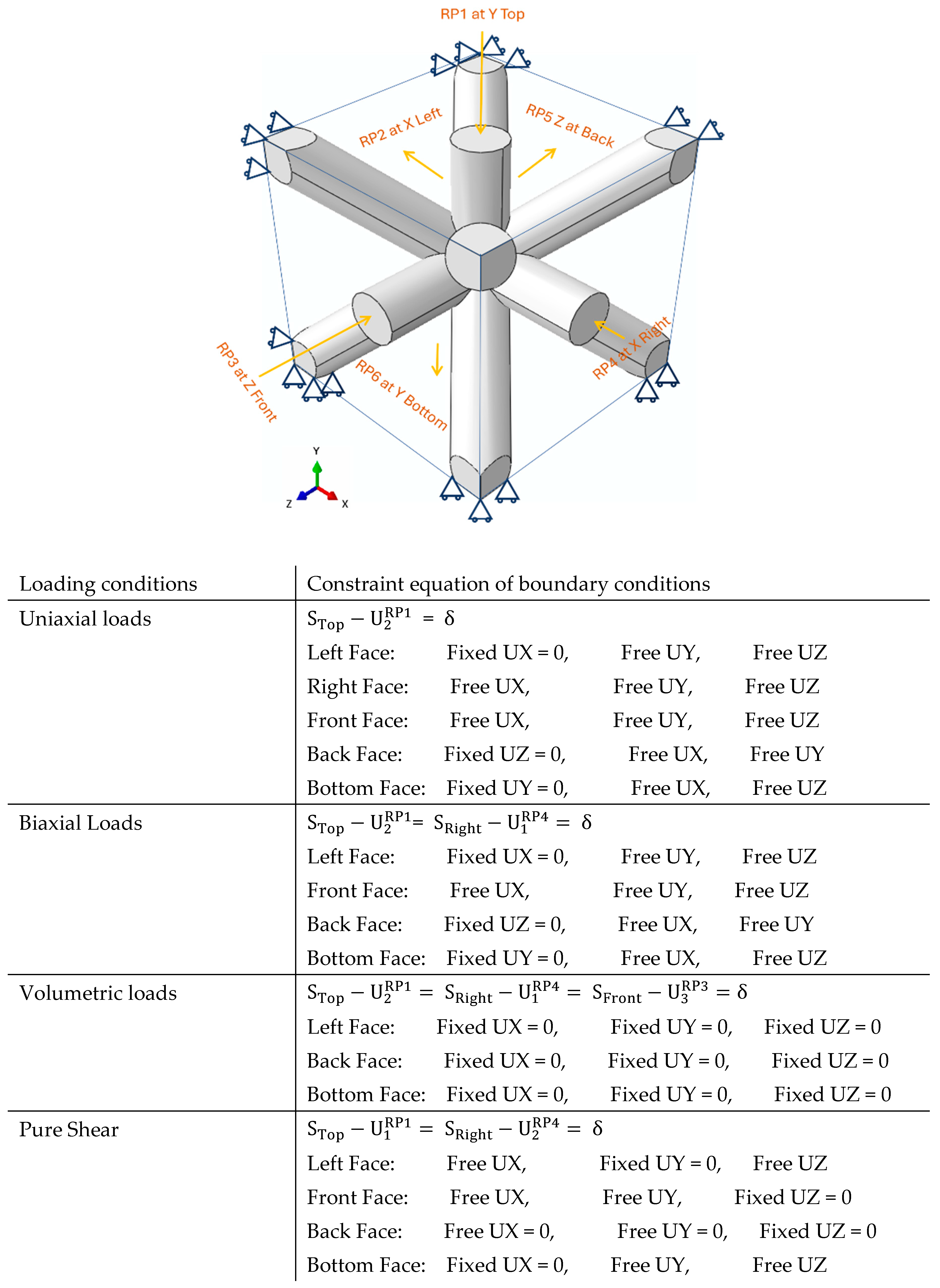
To apply the various boundary conditions on the unit cell model for different loading scenarios, we utilised the idea of coupling the surface of each side face of the unit cell with a reference point in each side face, as illustrated in Figure 3, and then implemented each boundary condition through constraint equations into each of the reference points through x, y, and z coordinates.
All the boundary conditions were then implemented into these reference points through constraint equations presented in Figure 3 for different loading conditions, including uniaxial, biaxial, shear, and volumetric boundary conditions in 3D. Each loading condition has its constraint equation, with some used to apply the displacement and others used to fix it in various directions with respect to the degree of freedom (DOF). The six faces of the displacement of the unit cell are denoted by where and the displacement of the unit cell with respect to boundary conditions for different loading conditions are denoted by , where represent the reference point number and represent the relevant degree of freedom that the constraint equation is applied to. Moreover, the displacement boundary condition denoted by can be used to calculate the deformation gradient as provided in Equation (1).
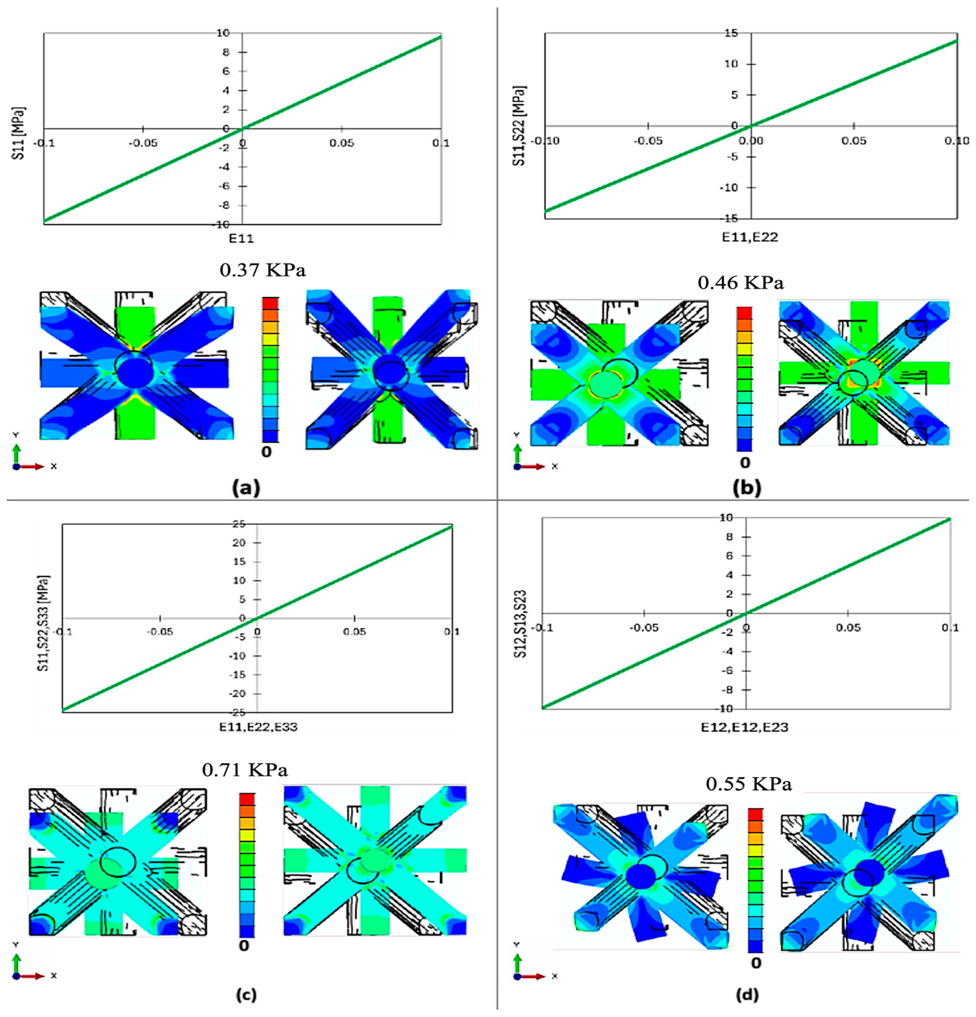
Upon completion of all sets of simulations, the stress–strain data was extracted for various loading conditions and then assembled to make the full comprehensive training data for the ANN model, which is developed in the next section. These simulations included the uniaxial loading in the x, y, and z direction, with both tensile and compression cases and biaxial loading on the x-y, y-z, and z-x axis, with both tensile, both compression and one tensile and one compression state, volumetric loading in expansion and contraction style, and finally pure shear loading in all xy, yz, and xz directions. Figure 4 represents the results of data collected from the numerical simulations along the stress contour plot for various loading scenarios, with the visual representation of the deformed unit cell under the (a) uniaxial and (b) biaxial loading test and (c) volumetric loading test; (d) illustrates the pure shear loading.
2.3. Additive Manufacturing of Lattice-Structured Specimens
The cell arrangement of the 3D lattice-structured material was prepared and additively manufactured for experimental study using Formlab3 Stereolithography (SLA) 3D-printing technology [35]. SLA 3D printing is a highly accurate technique of additive manufacturing that creates 3D models in a vat of ultraviolet (UV)-curable photopolymer. To obtain better surface finishes for our lattice model, we used SLA printers with XY resolution 25 microns (0.025 mm), with the smallest step size, and a 85-micron (0.085 mm) laser spot size.
2.4. Experimental Analysis
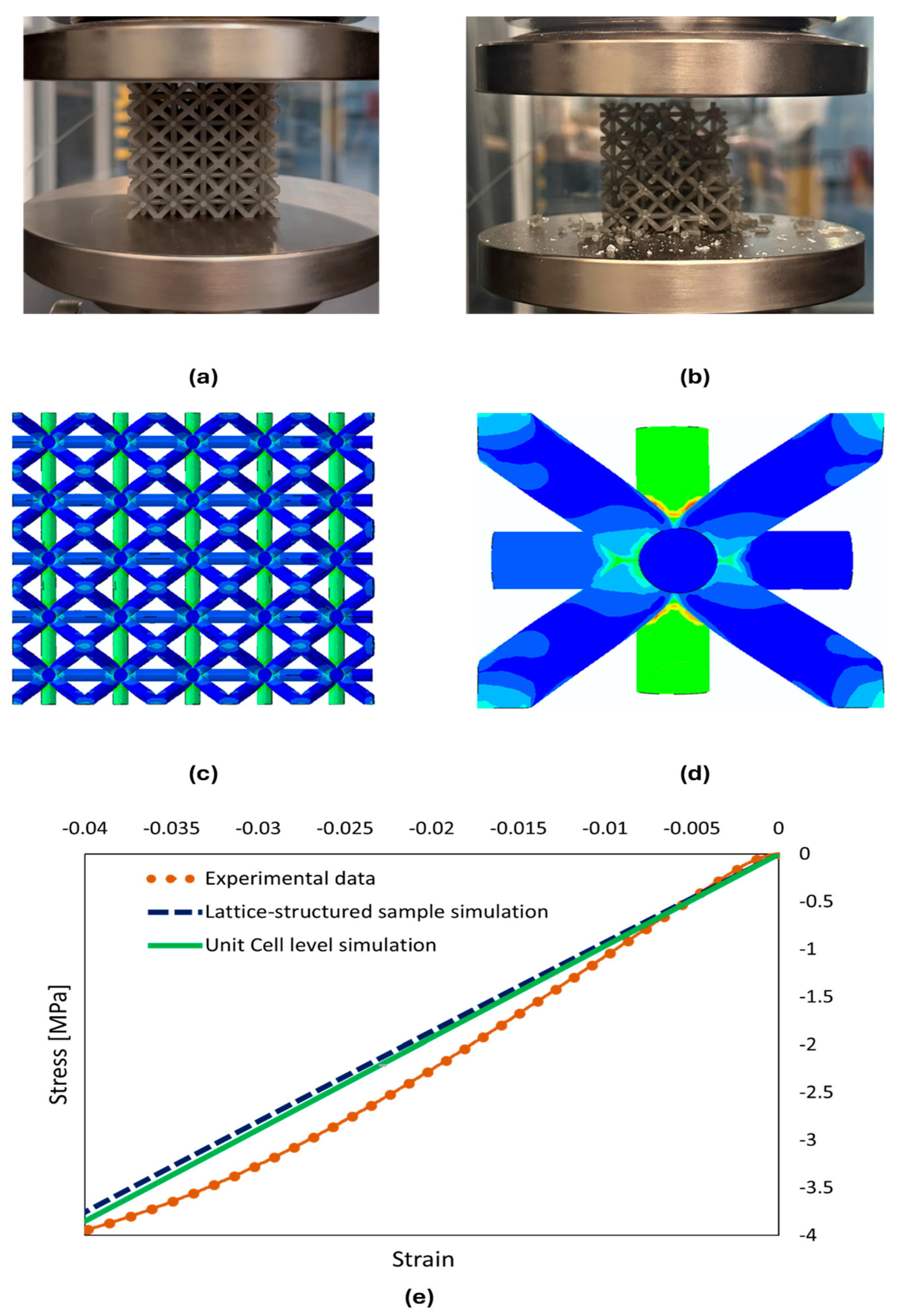
To validate the proposed constitutive model as well as finite element modelling to generate the data, an experimental compression test was conducted. The lattice-structured material specimen had an arrangement of cells and each cell was and the radius of the beam was 1 mm. The tests were performed at room temperature by using a 50 kN Zwick Roell universal testing machine, as shown in Figure 5. The lattice-structured of the draft resin specimen was positioned in the middle of support plates (Figure 5a), and the compression load was applied at the loading rate of 10 mm/min until the specimen failed (Figure 5b). The numerical simulation of the 3D lattice-structured material is shown in Figure 5c. Overall, as shown in Figure 5e, a good agreement in the stress–strain response was reached between the experimental results and simulated results for lattice-structured and unit cells under uniaxial compression load.
3. An ANN-Based Data-Driven Constitutive Model for Lattice-Structured Materials
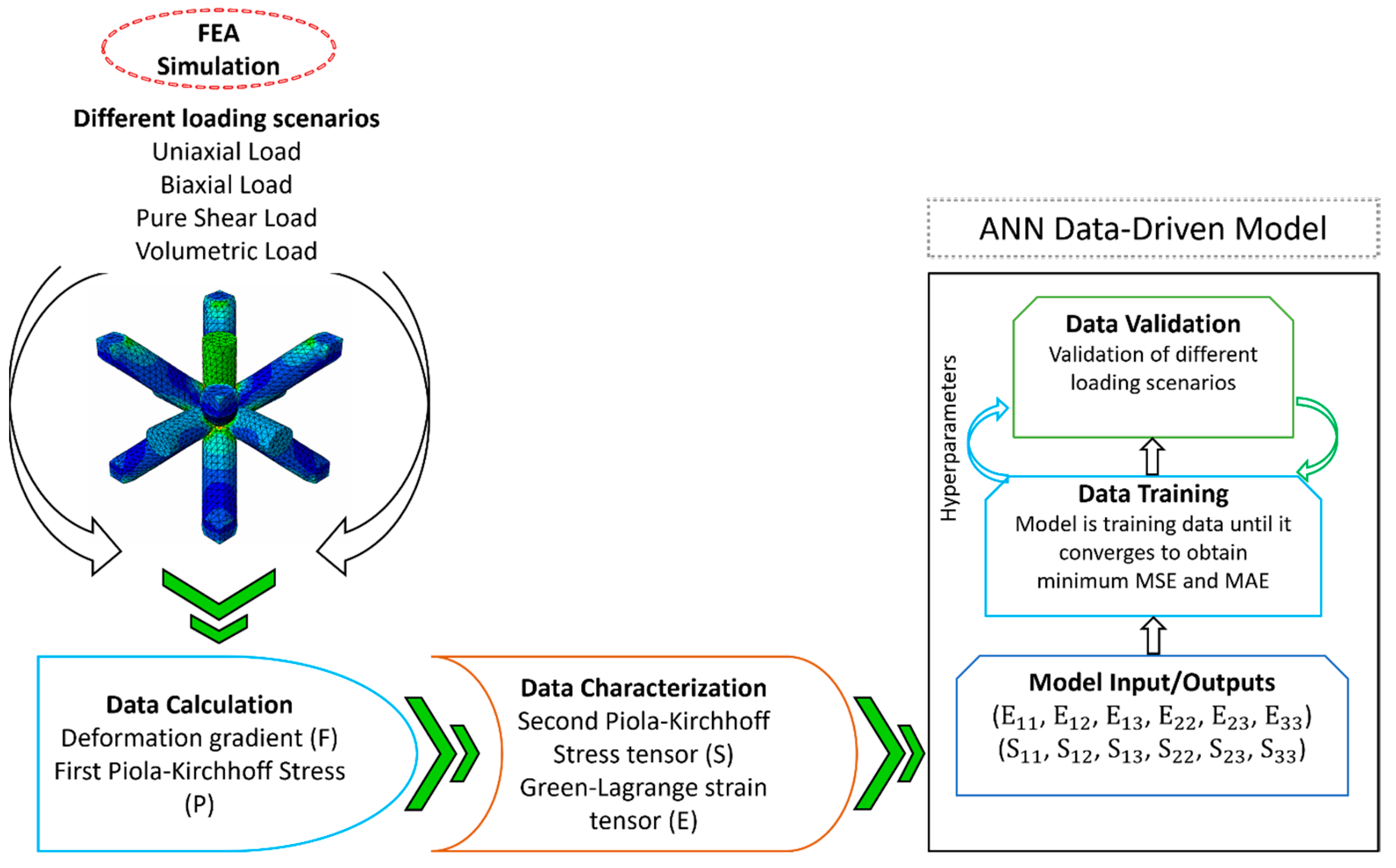
A data-driven constitutive model based on ANN was employed to represent the complex mechanical behaviour between a material’s input and output. ANN-based constitutive models are one the most extensively used ML algorithms in the research field of the mechanical behaviour of materials due to their exceptional prediction accuracy as well as being an extract of insightful information. Figure 6 illustrates the framework of the proposed ANN-based data-driven constitutive model for lattice-structured materials. The framework covers two important phases. The first phase is the implementation of the FEA simulation of unit cells under various loading scenarios such as uniaxial, biaxial, pure shear, and volumetric for data generation purposes. The data was exported from the simulations in the form of the deformation gradient and the first Piola–Kirchhoff stress, respectively. In the field of continuum mechanics, the relationship between the initial configuration and the current configuration is represented by the deformation gradient , as given in Equation (1).
where is the displacement vector u gradient with respect to the initial coordinates and I is the identity tensor. Similarly, the first Piola–Kirchhoff stress is defined as the forces acting in the current configuration to the area in the reference configuration.
We then converted the deformation gradient and the first Piola–Kirchhoff stress , into the symmetrical Green–Lagrange strain tensor , and the second Piola–Kirchhoff (PK2) stress tensor following Equations (2) and (3):
The second phase of the proposed framework is to use the ANN constitutive model to train the characterised data. The inputs for this constitutive model consisted of six independent components of the Green–Lagrange strain tensor , while the outputs comprised six independent components of the second Piola–Kirchhoff stress tensor . The ANN constitutive model would be trained based on these data for the three-dimensional behaviour of the lattice-structured material until the model converges and achieves a minimum mean-square error (MSE) and mean absolute error (MAE). Moreover, the constitutive model will be validated over different loading scenarios during the final stage of the framework.
3.1. ANN Model Architecture and Training
The right selection of prediction models depends on the specific problem and data at hand; however, each model has its strengths and weaknesses. Considering the purpose of the work (which is to develop the ANN model which could be employed for a wide range of lattice materials by only updating the dataset), an ANN outperformed other models in capturing such nonlinear and complex relationships between inputs and outputs. Also, decision trees can capture such behaviours but might not generalize to new datasets as the ANN works. Similarly, an ANN exhibits proficiency in feature extraction, scalability to large datasets, robustness to outliers and generalization to new data; for example, our ANN model performed well and effectively. Based on the relationship between design parameters and input parameters ANN offers diverse architecture and configuration options, providing control over multiple hyperparameters such as the number of layers, neurons, and activation functions. Furthermore, multiple regularization techniques can be incorporated into ANN to improve its overall performance [36,37,38].
An ANN constitutive model for a lattice-structured material was developed by training the model through the stress–strain dataset, which was gathered through the validated finite element simulations of the unit cell level under comprehensive loading scenarios. To identify the most accurate model and achieve the best predictability by the ANN model based on the available dataset, we tuned the hyperparameters of the ANN model, which have a substantial effect on the model’s accuracy and performance. Tuning hyperparameters is a vital phase in improving the accuracy and performance of any machine learning models, especially those used to predict material mechanical behaviour. Moreover, the overall performance of the constitutive model and its ability to capture complex relationships and generalize effectively to newly collected data can be fine-tuned by modifying these hyperparameters. The proposed constitutive model is the extended version of our previous work [39], with a new dataset for the novel design of the lattice-structured material. The proposed constitutive ANN model is shown in Figure 7.
The basic theoretical equation of the ANN model implementation can be expressed in Equation (4) as
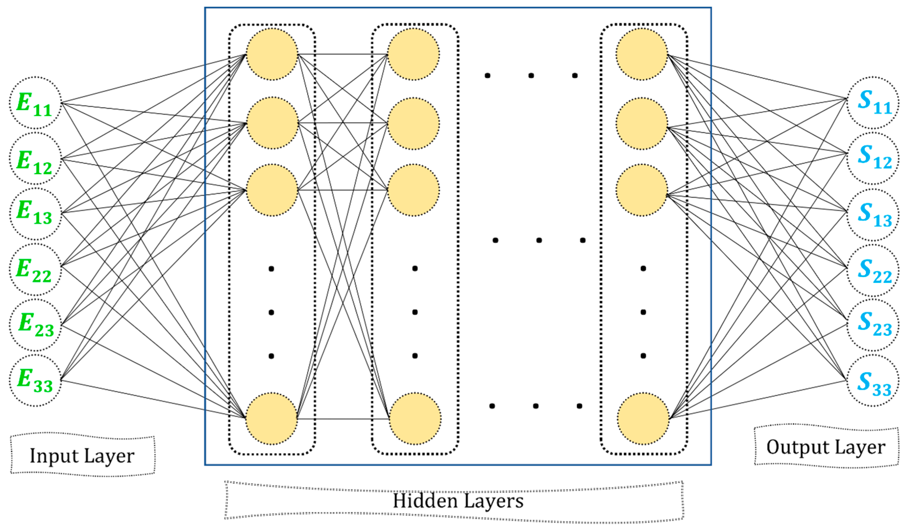
where is the output of the ANN model with total number of inputs, features, is the activation function and b is the bias term of the model. The proposed ANN constitutive model architecture has six layers. The input layer has six components of the Green–Lagrange strain tensor . The first hidden layer has 24 neurons, the second hidden layer has 16 neurons and the third and fourth hidden layers have 10 and 8 neurons, respectively. Moreover, the output layer of the model is designed to have six components of the second Piola–Kirchhoff stress tensor . Several important hyperparameters were tailored in our model to improve model generalization, accuracy, and validation for various loading scenarios. The proposed ANN constitutive model had where , is the number of neurons in the hidden layer . The activation function is a key hyperparameter that determines the behaviour of each layer in the model. It specifies how the model learns and reflects the intricate relationship between input data and output. The right selection of activation function depends on the nature of the data and the intended outcomes of the model. The nature of the dataset used in this study exhibits a wide range of values including negative values, which vary from minimum to maximum under different loading scenarios. We used the exponential linear unit (ELU) activation function in the proposed model for the first three hidden layers and the linear activation function for the fourth hidden layer. The ELU function has the advantage of not allowing negative values to generate zero gradients and allowing the model to learn despite negative inputs. Therefore, it helps to avoid the problems of dying neurons. In addition, we set the batch size to 32 in order to achieve better accuracy and generalization. However, it has been observed that the convergence speed is slightly reduced as compared to other batch sizes that have been studied. The accuracy performance of the model is measured by two common metrics, namely, the mean-squared error (MSE), shown in Equation (5), and mean absolute error (MAE), shown in Equation (6). Furthermore, the nature of the model was sequential, and the number of trainable parameters was 846.
In the given training dataset, denotes the actual components of the second Piola–Kirchhoff stress tensor from the training data, represents the predicted values of the second Piola–Kirchhoff stress tensor, and indicates the number of training data samples.
3.2. Performance of Trained ANN Model
The performance of the trained ANN model holds significant importance in evaluating how effectively and consistently the model performs for the task it designed. In this work, the performance of the ANN model was compared to relevant hyperparameters for its efficiency. This comparative analysis helps in determining the network’s effectiveness, reliability, and ability to generalize. Hence, the model was analysed by incorporating various activation functions and the batch size of the training data. The performance of the model was evaluated using MSE and MAE error values, which are shown in Table 1 for the LeakyReLU and the ELU activation functions. Moreover, the linear activation function was used in the last hidden layer of each configuration. We performed this comparison as these activation functions had the least MSE and MAE errors as compared to the other activation functions used during the training.
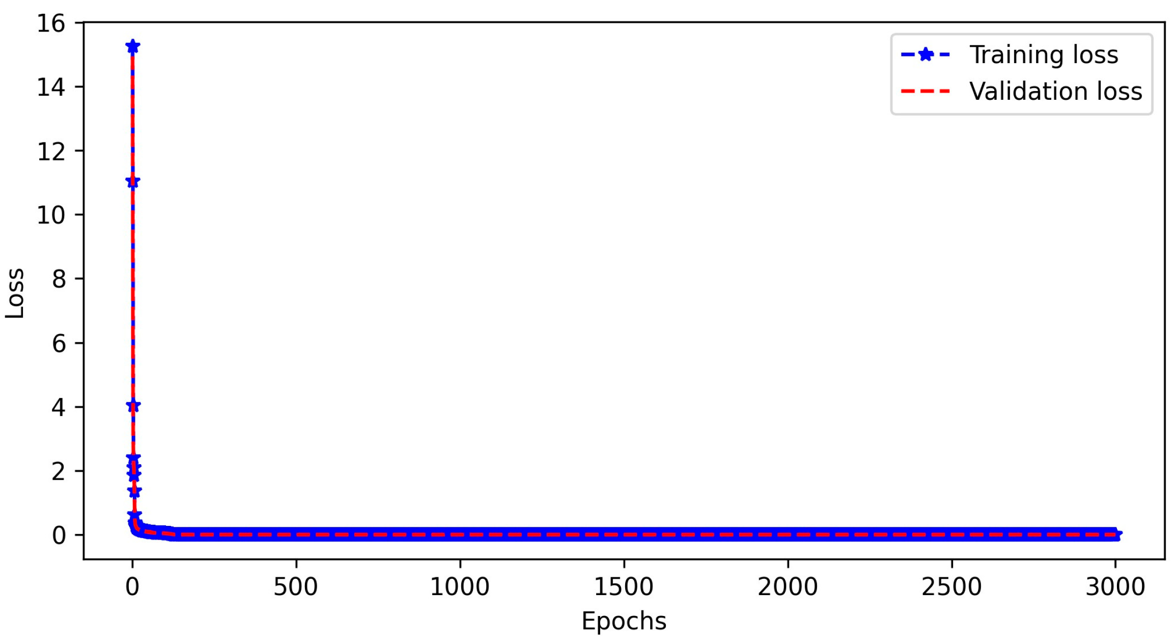
As it is observed in Table 1, the MSE and MAE values were lower for the tailored configuration, with a batch size of 32, and the ELU activation function when compared to other configurations. Furthermore, Figure 8 depicts the training and validation loss curves, commonly known as the learning curve for the final configuration. It was observed the learning curve for this configuration had epochs of 3000 and displayed better convergence in comparison to the learning curve of the other configuration that has been tried during training.
4. Results and Discussion
Upon completion of training of an ANN-based material model for the lattice-structured material in the previous section, we performed a comprehensive validation process using data which were not included in the training phase. Furthermore, the investigation of the generalization of the model for a wider group of material types was presented in this section.
4.1. Validation of the ANN Model under Various Loading Scenarios
The ANN constitutive model was rigorously tested to evaluate its performance and accuracy over different loading scenarios, including uniaxial, biaxial, volumetric, and pure shear scenarios. The comprehensive analysis included the model’s performance and accuracy being evaluated to provide a robust conclusion that the model effectively captured the three-dimensional mechanical behaviour of the lattice-structured material. Furthermore, the validation process on specific loading conditions would be the first step prior to the integration of the model into wider three-dimensional practical applications. Therefore, several loading conditions were chosen in this step, including, uniaxial, pure shear, biaxial, and volumetric loads, and the results predicted by the training model were compared with results from the validated finite element method. In each case, all six independent components of the second Piola-Kirshoff stress were investigated even if in specific cases the value was zero, and the results of these comparisons are presented in Figure 9, Figure 10, Figure 11 and Figure 12. Please note the data used in the validation process were completely separated from the training dataset and the ANN model had not seen them before.
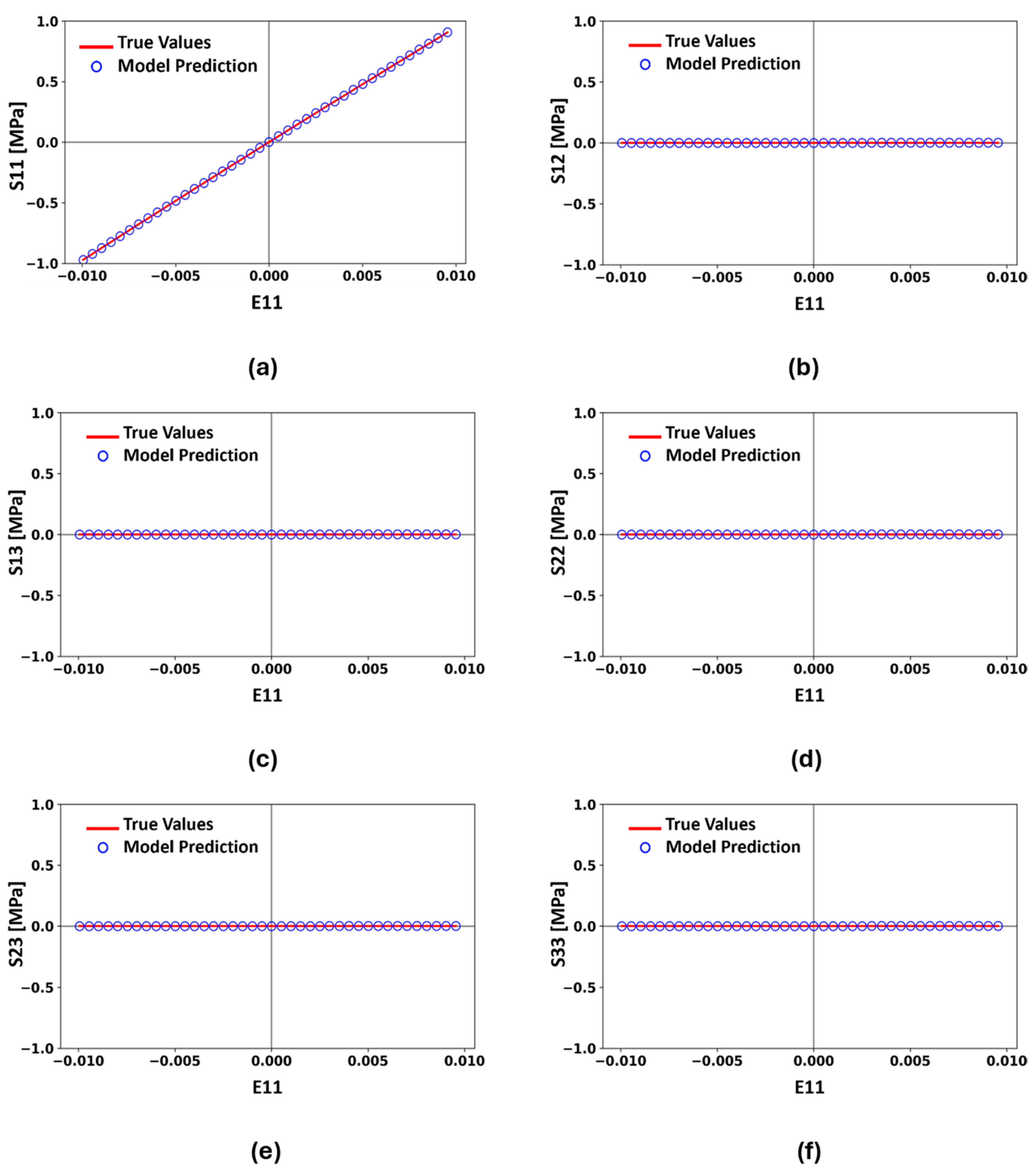
To evaluate the performance of the proposed ANN constitutive model under uniaxial loading, the true stress–strain values obtained from FEA simulation data were compared to the corresponding values predicted by the proposed model under uniaxial loading along the direction. All six independent components of the stress tensor (, , , , , and ) are presented in Figure 9 and they show the excellent agreement between the predicted values and real value from the full-scale simulation, which was previously validated with the experiment. It is worth mentioning that although several stress components were zero in the specific studies here, the prediction of zeros with acceptable error is an important factor for a trained ANN model.
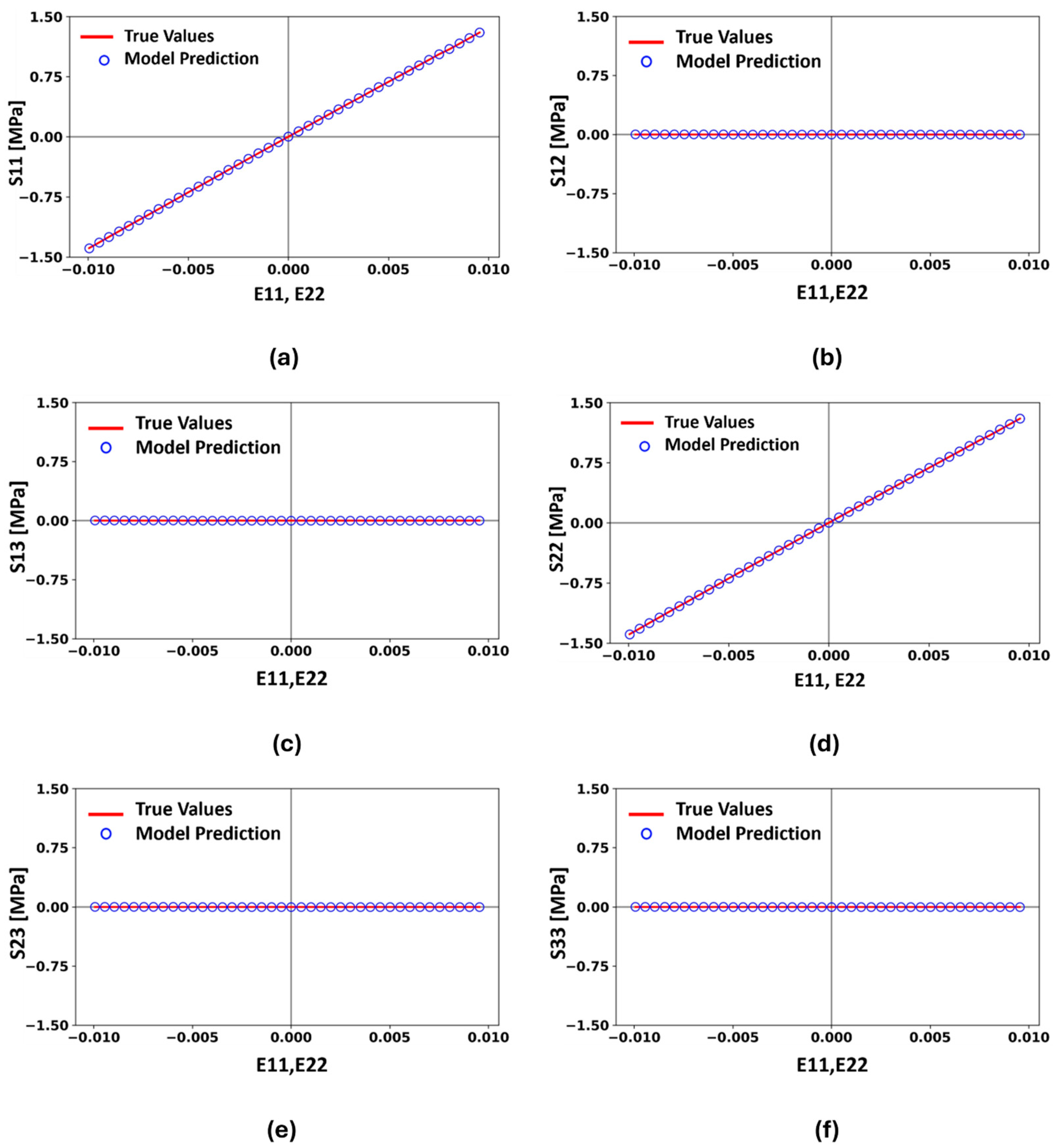
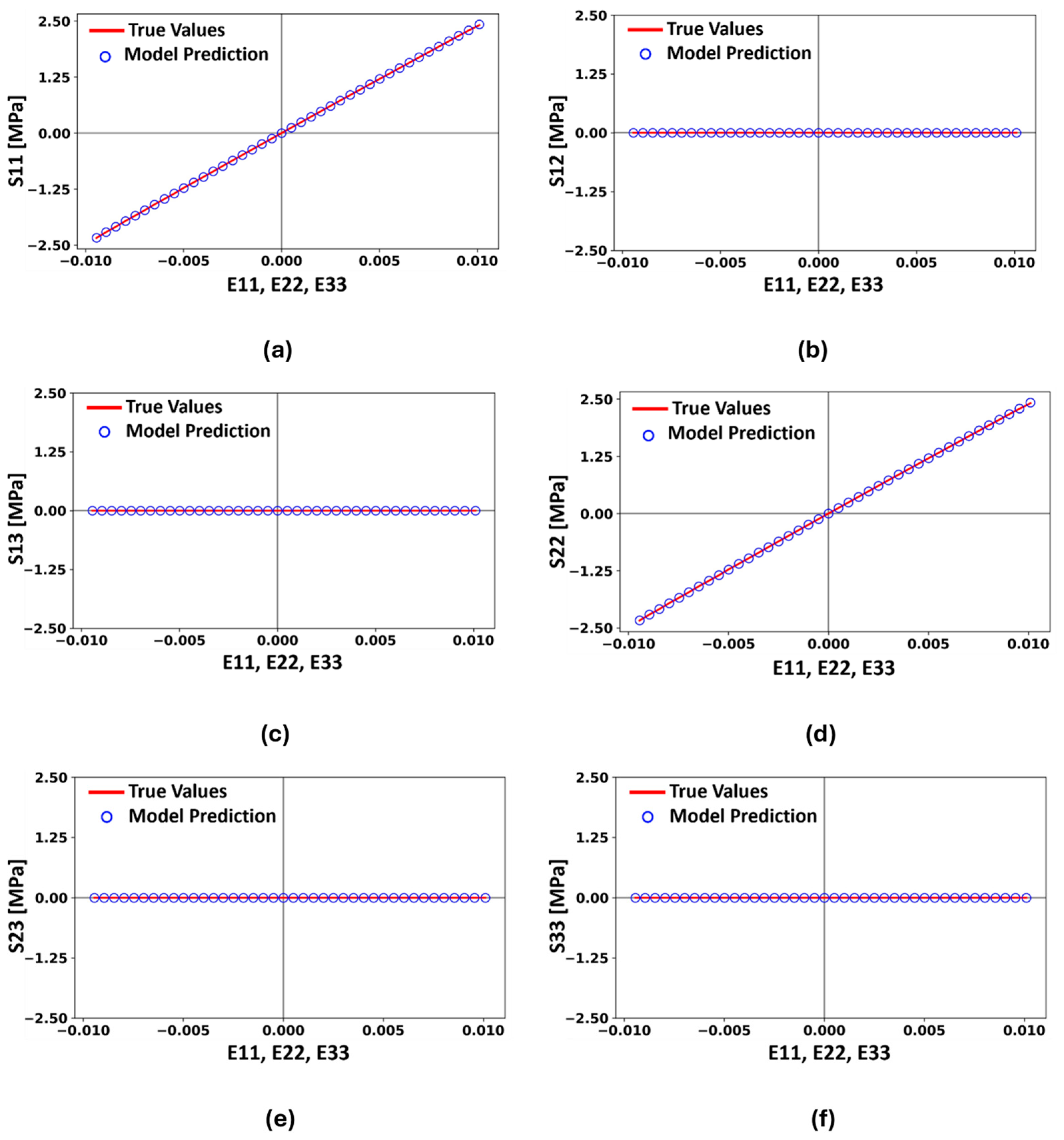
Similar comparisons for all the six independent stress components along loading strains are presented for Biaxial and volumetric loads in Figure 10 and Figure 11, respectively. In both figures, the axis demonstrates the measuring stress component while the axis represents the strain in the loading direction. For example, the stress is plotted with respect to and in Figure 10a–f where the loading for this case is in uniform biaxial load in the and directions, with both loads compressive or both loads tensile. Similarly, the independent stress components are plotted with respect to and , and in Figure 11a–f, where volumetric loading is applied uniformly as compression and tension in the , , and directions. Furthermore, as can be seen in Figure 10 and Figure 11, the predicted values from the proposed ANN model were in great agreement with the test data where these data were not met by the ANN model in the training step. Please also note the comparisons still showed a error in some cases which we assume might be in the order of round-off error of our data generation and simulations.
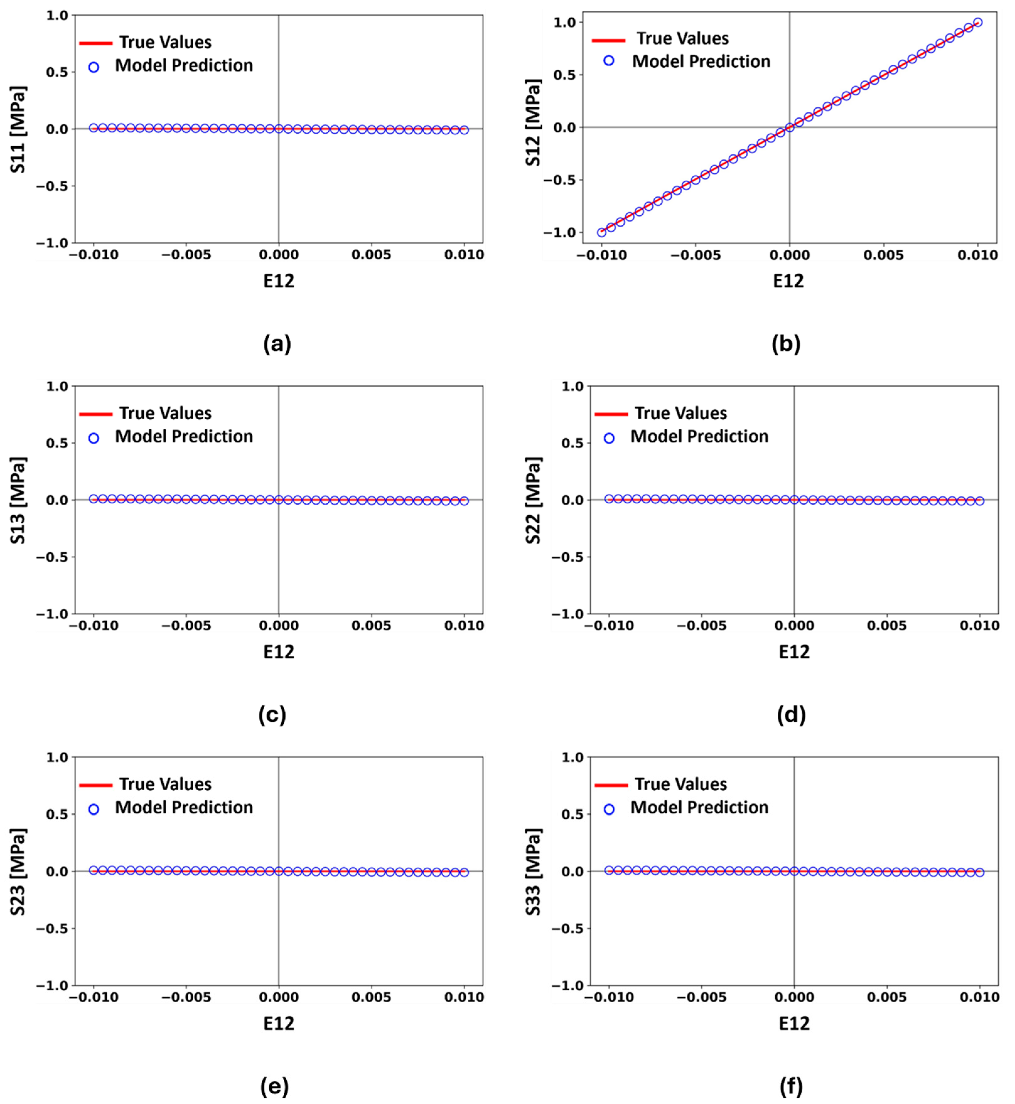
Finally, to ensure the performance of the developed ANN model under shear-type loadings, the model was tested under pure shear loading in different directions. Figure 11 represents the comparison of all stress components predicted by the trained model and true test values for pure shear loading on the plane. The shear tests were also carried out for other directions (e.g., and planes) but due to the symmetry of the structure, we did not repeat the results here. It is also worth mentioning that although five out of the six components under pure shear case had zero values, this could be a challenging case for an ANN structure to predict all zero values accurately and it is only achieved when the appropriate hyperparameters are chosen for the ANN model.
The developed ANN constitutive model in this study demonstrated remarkable prediction potential across all possible loading scenarios, including uniaxial, biaxial, volumetric, or pure shear and effectively represented the mechanical behaviour of the material. Such a robust performance reflects the accuracy and efficiency of our proposed ANN constitutive model in capturing and predicting the mechanical behaviour of the material. In the next part, we continue to test the performance of the model on different cases of parent material.
4.2. Generalization of the Model to the Wider Group of Materials
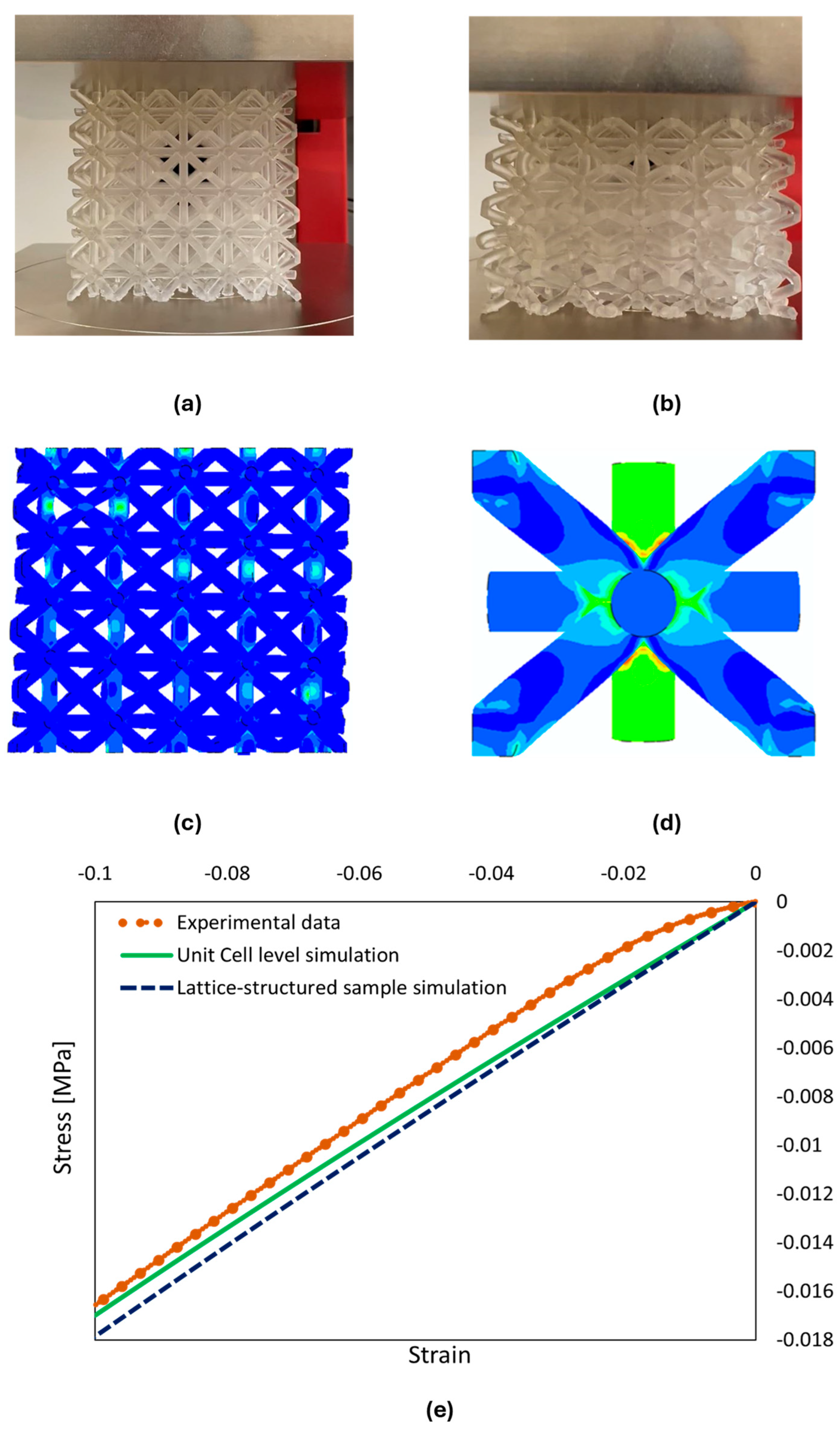
To demonstrate the robustness of the developed model to be utilised for a wider range of material types, we performed further case studies on lattice-structured materials with hyperelastic parent materials. We employed the Neo–Hookean model for the hyperelastic materials, with the parameters D1 = 0.191621338, C10 = 0.539857810 and C01 = 0.0. The physicochemical properties included a relative density of 1.02 g/cm3, boiling point > 100 °C, and flashpoint > 93.5 °C. We then followed the same data collection process which was described in Section 2 with accompanying unit cell-level simulations and experimental validation to update the dataset. The material used as the parent material of the lattice-structured sample in this case study was flexible in a Formlab 3D-printer, illustrating hyperelastic behaviour. The stress–strain relationships were then obtained under various loading scenarios such as compression, tensile, pure shear, biaxial, and volumetric loadings. Figure 13a presents the lattice-structured sample made of a rubber-like material positioned for compression test. The experiment was performed at room temperature by using a Zwick/Roell universal testing machine with a loading speed of 10 mm/min and an applied load of 500 N. The unit cell-level and sample-level simulations, which were used for completing the data generation process, were then validated by experimental data under compression load. The deformed contour plot of the unit cell-level and full-scale model of the flexible lattice-structured material is shown in Figure 13b,c. Furthermore, the stress–strain response for the experimental results and FEA-simulated results of the lattice-structured and the unit cell of the lattice-structured are compared in Figure 13d for the purpose of validation of the data collection model.
In addition, Figure 13a presents the lattice-structured made of a rubber-like material positioned for the compression test. The experiment was performed at room temperature by using a Zwick/Roell universal testing machine, with a loading speed of 10 mm/min and an applied load of 500 N. The lattice-structured material displayed a large level of deformation while having relatively small values of stress. The numerical simulation of the lattice-structured flexible material is shown in Figure 13b. Furthermore, the stress–strain response for the experimental results and finite element simulations of the lattice-structured material and the unit cell of the lattice-structured model were also in good agreement with the flexible material, as shown in Figure 13c. Although there was an initial variation because of the free load, it was not significant. In general, the constitutive model was experimentally validated with the FEA simulations model for flexible materials.
We then trained our ANN constitutive model using a dataset obtained from FEA simulations of the rubber-like lattice-structured material under various loading scenarios, as discussed earlier. We updated the hyperparameters of our model that effectively trained for the draft material dataset. Moreover, the aim was to optimize the model’s performance by changing the hyperparameters, particularly for the complex mechanical behaviour of the flexible material dataset. As a result, the optimum model configuration for the rubber-like material dataset had an input and output layer and four hidden layers. The layer sequence included a particular number of neurons in each layer as follows: (6 16121086). The input layer had six independent components of , and the four hidden layers had 16, 10 and 8 neurons, while the outputs comprised six independent components of . Furthermore, the scaled exponential linear units (SELU) served as the activation function in each layer, and the model was trained through 250 epochs with a batch size of 14. The inherent self-normalization property of the SELU activation function enabled it to effectively mitigate the vanishing gradient issue during training. Thus, this configuration showed the best performance for predicting the accurate mechanical behaviour of the flexible material [40]. The performance of the trained model was then evaluated by the MSE and MAE metrics. For the current configuration, the lowest MSE and MAE values achieved were 5.33 × 10⁻⁶ and 3.92 × 10⁻³, respectively, consisting of 588 total trainable parameters.
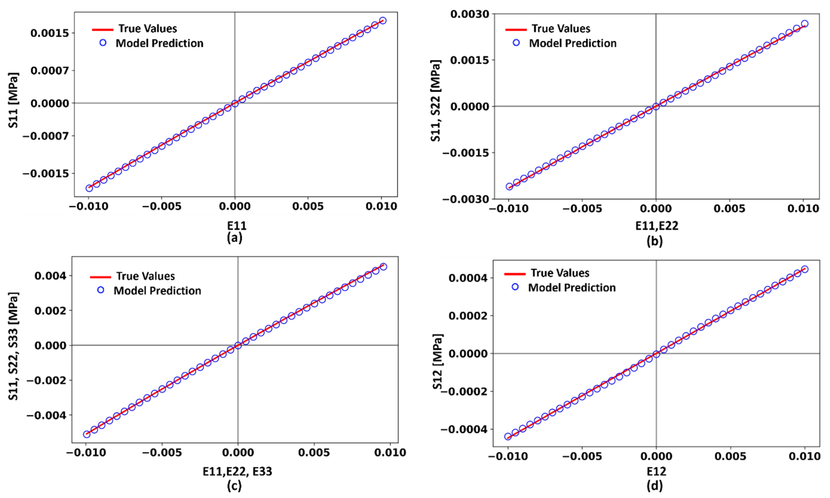
Finally, we performed various tests on the newly trained ANN model for a hyperelastic lattice-structured material, similar to the validation tests described in Section 4.1 for the main model. For these purposes, a group of test datasets including uniaxial, biaxial, volumetric, and pure shear loading scenarios were considered. These datasets were not used during training steps and are dedicated to validation tests only. The predicted results of our trained ANN constitutive model for hyperelastic lattice-structured material compared with the true test values under various loading are presented in Figure 14. For the sake of brevity, we presented only the non-zero stress components from various loading scenarios.
In addition, the model was validated over different loading scenarios for the flexible material dataset obtained from FEA simulations. The predicted results of our trained ANN constitutive model for flexible materials displayed excellent agreement with the true values under various loading scenarios, as shown in Figure 14. As can be seen in Figure 14a–d, the developed ANN constitutive model demonstrated a high level of efficiency and robustness to represent and capture the mechanical behaviour of the hyperelastic lattice-structured material under three-dimensional loadings.
5. Conclusions
In the present study, we developed a supervised machine learning algorithm by employing the ANN model constitutive model to predict the mechanical behaviour of a new lattice-structured material efficiently and accurately. In particular, our ANN constitutive model demonstrated excellent convergence and accuracy in predicting mechanical behaviour under various one-, two- and three-dimensional loading scenarios, including uniaxial, biaxial, volumetric, and pure shear. The comprehensive training dataset for our constitutive model was obtained by conducting a hybrid method, including unit cell-level finite element simulations and experimental validations. We then proposed an ANN structure to be trained between three-dimensional strain as input and second Piola–Kirshhoff stress components as output. Furthermore, the proposed ANN-based constitutive model perfectively converged and was validated for various loading scenarios in the three-dimensional domain.
To investigate the ability of generalization of the model to the wider group of material types, we studied adapting the same ANN model structure to the hyperelastic lattice-structured material, which had the same lattice geometry, but replacing the parent material with hyperelastic material. The new lattice could be loaded under large deformation and the dataset updated by following the same data generation methodology. The same ANN structured the retrained using the new dataset and the hyperparameters updated. We then observed that the new model could perfectly predict the mechanical behaviour of the hyperelastic lattice-structured material under various loadings in a three-dimensional domain. Thus, it could be concluded that the proposed model has the potential to effectively capture and predict the mechanical behaviour of some other types of materials with relevant physical behaviour only updating the input dataset.
Our proposed ANN constitutive model efficiently represents the isotropic mechanical behaviour of lattice-structured material over different loading scenarios. However, the horizon of the developed model could be extended beyond its current state, for example, into anisotropic material behaviour. Moreover, future studies will involve the integration of our proposed model with the FEA modelling for various 3D complex case study simulations, which will open avenues for broader applications and advancements in this area of research.
Author Contributions
Conceptualization, A.H., A.H.S. and M.S.; methodology, A.H., A.H.S. and M.S.; software, A.H. and A.H.S.; validation, A.H. and A.H.S.; formal analysis, A.H.; investigation, A.H.; resources, A.H.S.; data curation, A.H.; writing—original draft preparation, A.H.; writing—review and editing, A.H.S. and M.S.; visualization, A.H.; supervision, A.H.S.; project administration, A.H.S. and M.S.; funding acquisition, A.H.S. All authors have read and agreed to the published version of the manuscript.
Funding
This research received no external funding.
Data Availability Statement
The original contributions presented in the study are included in the article further inquiries can be directed to the corresponding authors.
Conflicts of Interest
The authors declare no conflicts of interest. The funders had no role in the design of the study; in the collection, analyses, or interpretation of data; in the writing of the manuscript; or in the decision to publish the results.
References
- Wang, P.; Yang, F.; Li, P.; Zhang, W.; Lu, G.; Fan, H. Bio-inspired vertex modified lattice with enhanced mechanical properties. Int. J. Mech. Sci. 2023, 244, 108081. [Google Scholar] [CrossRef]
- Yu, X.; Zhou, J.; Liang, H.; Jiang, Z.; Wu, L. Mechanical metamaterials associated with stiffness, rigidity and compressibility: A brief review. Prog. Mater. Sci. 2018, 94, 114–173. [Google Scholar] [CrossRef]
- Rahmani, R.; Antonov, M.; Brojan, M. Lightweight 3D printed Ti6Al4V-AlSi10Mg hybrid composite for impact resistance and armor piercing shielding. J. Mater. Res. Technol. 2020, 9, 13842–13854. [Google Scholar] [CrossRef]
- Xiao, R.; Li, X.; Jia, H.; Surjadi, J.U.; Li, J.; Lin, W.; Gao, L.; Chirarattananon, P.; Lu, Y. 3D printing of dual phase-strengthened microlattices for lightweight micro aerial vehicles. Mater. Des. 2021, 206, 109767. [Google Scholar] [CrossRef]
- Syrlybayev, D.; Perveen, A.; Talamona, D. Experimental investigation of mechanical properties and energy absorption capabilities of hybrid lattice structures manufactured using fused filament fabrication. Int. J. Adv. Manuf. Technol. 2023, 125, 2833–2850. [Google Scholar] [CrossRef]
- Al-Saedi, D.S.J.; Masood, S.H.; Faizan-Ur-Rab, M.; Alomarah, A.; Ponnusamy, P. Mechanical properties and energy absorption capability of functionally graded F2BCC lattice fabricated by SLM. Mater. Des. 2018, 144, 32–44. [Google Scholar] [CrossRef]
- Gan, J.; Li, F.; Li, K.; Li, E.; Li, B. Dynamic failure of 3D printed negative-stiffness meta-sandwich structures under repeated impact loadings. Compos. Sci. Technol. 2023, 234, 109928. [Google Scholar] [CrossRef]
- Bohara, R.P.; Linforth, S.; Nguyen, T.; Ghazlan, A.; Ngo, T. Anti-blast and -impact performances of auxetic structures: A review of structures, materials, methods, and fabrications. Eng. Struct. 2023, 276, 115377. [Google Scholar] [CrossRef]
- Imediegwu, C.; Grimm, U.; Moat, R.; Jowers, I. A computational method for determining the linear elastic properties of 2D aperiodic lattice structures. J. Strain Anal. Eng. Des. 2023, 58, 590–602. [Google Scholar] [CrossRef]
- du Plessis, A.; Broeckhoven, C.; Yadroitsava, I.; Yadroitsev, I.; Hands, C.H.; Kunju, R.; Bhate, D. Beautiful and Functional: A Review of Biomimetic Design in Additive Manufacturing. Addit. Manuf. 2019, 27, 408–427. [Google Scholar] [CrossRef]
- Ramakrishna, D.; Murali, G.B. Bio-inspired 3D-printed lattice structures for energy absorption applications: A review. Proc. Inst. Mech. Eng. Part L J. Mater. Des. Appl. 2022, 237, 503–542. [Google Scholar] [CrossRef]
- Hulme, J.; Sakhaei, A.H.; Shafiee, M. Mechanical analysis and additive manufacturing of 3D-printed lattice materials for bone scaffolds. Mater. Today Proc. 2023. [Google Scholar] [CrossRef]
- Kirchdoerfer, T.; Ortiz, M. Data-driven computational mechanics. Comput. Methods Appl. Mech. Eng. 2016, 304, 81–101. [Google Scholar] [CrossRef]
- Stainier, L.; Leygue, A.; Ortiz, M. Model-free data-driven methods in mechanics: Material data identification and solvers. Comput. Mech. 2019, 64, 381–393. [Google Scholar] [CrossRef]
- Ibañez, R.; Abisset-Chavanne, E.; Aguado, J.V.; Gonzalez, D.; Cueto, E.; Chinesta, F. A Manifold Learning Approach to Data-Driven Computational Elasticity and Inelasticity. Arch. Comput. Methods Eng. 2018, 25, 47–57. [Google Scholar] [CrossRef]
- Ibáñez, R.; Abisset-Chavanne, E.; González, D.; Duval, J.-L.; Cueto, E.; Chinesta, F. Hybrid constitutive modeling: Data-driven learning of corrections to plasticity models. Int. J. Mater. Form. 2019, 12, 717–725. [Google Scholar] [CrossRef]
- Huang, D.; Fuhg, J.N.; Weißenfels, C.; Wriggers, P. A machine learning based plasticity model using proper orthogonal decomposition. Comput. Methods Appl. Mech. Eng. 2020, 365, 113008. [Google Scholar] [CrossRef]
- Bessa, M.A.; Glowacki, P.; Houlder, M. Bayesian machine learning in metamaterial design: Fragile becomes supercompressible. Adv. Mater. 2019, 31, 1904845. [Google Scholar] [CrossRef]
- Shokry, A.; Gowid, S.; Kharmanda, G.; Mahdi, E. Constitutive Models for the Prediction of the Hot Deformation Behavior of the 10%Cr Steel Alloy. Materials 2019, 12, 2873. [Google Scholar] [CrossRef]
- Bock, F.E.; Aydin, R.C.; Cyron, C.J.; Huber, N.; Kalidindi, S.R.; Klusemann, B. A Review of the Application of Machine Learning and Data Mining Approaches in Continuum Materials Mechanics. Front. Mater. 2019, 6, 110. [Google Scholar] [CrossRef]
- Peng, X.-L.; Xu, B.-X. Data-driven inverse design of composite triangular lattice structures. Int. J. Mech. Sci. 2024, 265, 108900. [Google Scholar] [CrossRef]
- Fernández, M.; Jamshidian, M.; Böhlke, T.; Kersting, K.; Weeger, O. Anisotropic hyperelastic constitutive models for finite deformations combining material theory and data-driven approaches with application to cubic lattice metamaterials. Comput. Mech. 2021, 67, 653–677. [Google Scholar] [CrossRef]
- Klein, D.K.; Fernández, M.; Martin, R.J.; Neff, P.; Weeger, O. Polyconvex anisotropic hyperelasticity with neural networks. J. Mech. Phys. Solids 2022, 159, 104703. [Google Scholar] [CrossRef]
- Chung, I.; Im, S.; Cho, M. A neural network constitutive model for hyperelasticity based on molecular dynamics simulations. Int. J. Numer. Methods Eng. 2021, 122, 5–24. [Google Scholar] [CrossRef]
- Bogusz, P.; Popławski, A.; Stankiewicz, M.; Kowalski, B. Experimental Research of Selected Lattice Structures Developed with 3D Printing Technology. Materials 2022, 15, 378. [Google Scholar] [CrossRef] [PubMed]
- Xia, H.; Meng, J.; Liu, J.; Ao, X.; Lin, S.; Yang, Y. Evaluation of the Equivalent Mechanical Properties of Lattice Structures Based on the Finite Element Method. Materials 2022, 15, 2993. [Google Scholar] [CrossRef] [PubMed]
- Riva, L.; Ginestra, P.S.; Ceretti, E. Mechanical characterization and properties of laser-based powder bed–fused lattice structures: A review. Int. J. Adv. Manuf. Technol. 2021, 113, 649–671. [Google Scholar] [CrossRef]
- Refai, K.; Montemurro, M.; Brugger, C.; Saintier, N. Determination of the effective elastic properties of titanium lattice structures. Mech. Adv. Mater. Struct. 2020, 27, 1966–1982. [Google Scholar] [CrossRef]
- Zhao, M.; Liu, F.; Fu, G.; Zhang, D.Z.; Zhang, T.; Zhou, H. Improved Mechanical Properties and Energy Absorption of BCC Lattice Structures with Triply Periodic Minimal Surfaces Fabricated by SLM. Materials 2018, 11, 2411. [Google Scholar] [CrossRef]
- Tancogne-Dejean, T.; Mohr, D. Stiffness and specific energy absorption of additively-manufactured metallic BCC metamaterials composed of tapered beams. Int. J. Mech. Sci. 2018, 141, 101–116. [Google Scholar] [CrossRef]
- Seharing, A.; Azman, A.H.; Abdullah, S. A review on integration of lightweight gradient lattice structures in additive manufacturing parts. Adv. Mech. Eng. 2020, 12, 1687814020916951. [Google Scholar] [CrossRef]
- Pan, C.; Han, Y.; Lu, J. Design and optimization of lattice structures: A review. Appl. Sci. 2020, 10, 6374. [Google Scholar] [CrossRef]
- MEGATrends. Abaqus 2022|Dassault Systèmes®. Available online: https://events.3ds.com/abaqus-2022 (accessed on 10 March 2023).
- “Draft Resin for Truly Rapid Prototyping.” N.p., n.d. Web. Available online: https://dental-media.formlabs.com/datasheets/2001477-TDS-ENUS-0.pdf (accessed on 13 March 2024).
- Formlabs. Formlabs 3D Printers Catalog. Available online: https://formlabs.com/uk/3d-printers/catalog/#form-3 (accessed on 7 March 2023).
- Zhang, W.; Zhang, R.; Wu, C.; Goh AT, C.; Lacasse, S.; Liu, Z.; Liu, H. State-of-the-art review of soft computing applications in underground excavations. Geosci. Front. 2020, 11, 1095–1106. [Google Scholar] [CrossRef]
- Argatov, I. Artificial neural networks (ANNs) as a novel modeling technique in tribology. Front. Mech. Eng. 2019, 5, 30. [Google Scholar] [CrossRef]
- Stergiou, K.; Ntakolia, C.; Varytis, P.; Koumoulos, E.; Karlsson, P.; Moustakidis, S. Enhancing property prediction and process optimization in building materials through machine learning: A review. Comput. Mater. Sci. 2023, 220, 112031. [Google Scholar] [CrossRef]
- Hussain, A.; Sakhaei, A.H.; Shafiee, M. Development of an Artificial Neural Network (ANN) Constitutive Model for Mechanical Metamaterials. Am. Soc. Mech. Eng. Digit. Collect. 2023, 3, V003T03A041. [Google Scholar]
- Tomar, A.S.; Sharma, A.; Shrivastava, A.; Rana, A.S.; Yadav, P. A Comparative Analysis of Activation Function, Evaluating their Accuracy and Efficiency when Applied to Miscellaneous Datasets. In Proceedings of the 2023 2nd International Conference on Applied Artificial Intelligence and Computing (ICAAIC), Salem, India, 4–6 May 2023; pp. 1035–1042. [Google Scholar]
Figure 1.
Design of unit and lattice-structured material, (a) a grid unit cell, (b) BCC unit cell, (c) merged unit cell of the grid and BCC unit cells, and (d) complete lattice-structured.
Figure 1.
Design of unit and lattice-structured material, (a) a grid unit cell, (b) BCC unit cell, (c) merged unit cell of the grid and BCC unit cells, and (d) complete lattice-structured.

Figure 2.
Meshed model of (a) unit cell level, and (b) full lattice-structured sample model for finite element simulations.
Figure 2.
Meshed model of (a) unit cell level, and (b) full lattice-structured sample model for finite element simulations.

Figure 3.
Constraint equations and boundary conditions in the 3D domain coupled to each side surface of the unit cell.
Figure 3.
Constraint equations and boundary conditions in the 3D domain coupled to each side surface of the unit cell.

Figure 4.
All loading conditions with stress-strain relations: (a) uniaxial, (b) biaxial, (c) volumetric, and (d) pure shear.
Figure 4.
All loading conditions with stress-strain relations: (a) uniaxial, (b) biaxial, (c) volumetric, and (d) pure shear.

Figure 5.
Comparison of experimental and simulation results of draft material: (a) lattice-structured specimen in the compression test, (b) test-to-break (failure) compression test, (c) finite element simulation of full 3D lattice-structured sample, (d) unit cell-level simulation, (e) stress-strain response of lattice-structured material in both experimental settings and simulation and unit cell simulation.

Figure 6.
The framework of generation of the proposed ANN-based constitutive model for lattice-structured materials, including the data generation phase.
Figure 6.
The framework of generation of the proposed ANN-based constitutive model for lattice-structured materials, including the data generation phase.

Figure 7.
Schematic architecture of an ANN constitutive model.

Figure 8.
The learning curve of the ANN constitutive model for the final configuration.

Figure 9.
Comparison of the stress components of (a) S11, (b) S12, (c) S13, (d) S22, (e) S23, and (f) S33 with respect to strain , between the predicted values and true test values under uniaxial compression and tensile loading conditions along the direction.
Figure 9.
Comparison of the stress components of (a) S11, (b) S12, (c) S13, (d) S22, (e) S23, and (f) S33 with respect to strain , between the predicted values and true test values under uniaxial compression and tensile loading conditions along the direction.

Figure 10.
Comparison of the stress components of (a) S11, (b) S12, (c) S13, (d) S22, (e) S23, and (f) S33 with respect to strain and , between the predicted values and true test values under uniform compressive and tensile biaxial loading conditions along the and directions.
Figure 10.
Comparison of the stress components of (a) S11, (b) S12, (c) S13, (d) S22, (e) S23, and (f) S33 with respect to strain and , between the predicted values and true test values under uniform compressive and tensile biaxial loading conditions along the and directions.

Figure 11.
Comparison of the stress components of (a) S11, (b) S12, (c) S13, (d) S22, (e) S23, and (f) S33 with respect to strain , , and , between the predicted values and true test values under uniform compressive and tensile volumetric loading conditions along the , , directions.
Figure 11.
Comparison of the stress components of (a) S11, (b) S12, (c) S13, (d) S22, (e) S23, and (f) S33 with respect to strain , , and , between the predicted values and true test values under uniform compressive and tensile volumetric loading conditions along the , , directions.

Figure 12.
Comparison of the stress components of (a) S11, (b) S12, (c) S13, (d) S22, (e) S23, and (f) S33 with respect to strain , between the predicted values and true test values under pure shear loading conditions on the plane.
Figure 12.
Comparison of the stress components of (a) S11, (b) S12, (c) S13, (d) S22, (e) S23, and (f) S33 with respect to strain , between the predicted values and true test values under pure shear loading conditions on the plane.

Figure 13.
Comparison between experimental and simulation results comparison for rubber-like material, (a) lattice-structured specimen in the compression test, (b) testing compression until failure, (c) full sample finite element simulation, (d) full sample finite element simulation, and (e) stress-strain response of lattice-structured experimental model, full scale simulation, and unit cell simulation.

Figure 14.
Comparison of the stress components between the predicted values and true test values under (a) uniaxial loading in the direction, (b) biaxial loading in the and directions, (c) volumetric loading, and (d) pure shear on the plane.
Figure 14.
Comparison of the stress components between the predicted values and true test values under (a) uniaxial loading in the direction, (b) biaxial loading in the and directions, (c) volumetric loading, and (d) pure shear on the plane.


Table 1.
Various configurations of the ANN model.
| Activation Function | Layers with Neurons | MSE | MAE | Batch Size | Epochs | Params |
|---|---|---|---|---|---|---|
| LeakyReLU, linear | [6,24,16,10,8,6] | 1.43 × 10⁻⁵ | 2.93 × 10⁻² | 32 | 2500 | 880 |
| LeakyReLU, linear | [6,24,16,10,8,6] | 4.47 × 10⁻⁶ | 2.86 × 10⁻² | 32 | 3000 | 880 |
| ELU, linear | [6,24,16,10,8,6] | 4.90 × 10⁻⁶ | 0.13 × 10⁻² | 32 | 2500 | 880 |
| ELU, linear | [6,24,16,10,8,6] | 1.16 × 10⁻² | 0.11 × 10⁻² | 32 | 3000 | 880 |
Disclaimer/Publisher’s Note: The statements, opinions and data contained in all publications are solely those of the individual author(s) and contributor(s) and not of MDPI and/or the editor(s). MDPI and/or the editor(s) disclaim responsibility for any injury to people or property resulting from any ideas, methods, instructions or products referred to in the content. |
© 2024 by the authors. Licensee MDPI, Basel, Switzerland. This article is an open access article distributed under the terms and conditions of the Creative Commons Attribution (CC BY) license (https://creativecommons.org/licenses/by/4.0/).
Share and Cite
MDPI and ACS Style
Hussain, A.; Sakhaei, A.H.; Shafiee, M. A Data-Driven Constitutive Model for 3D Lattice-Structured Material Utilising an Artificial Neural Network. Appl. Mech. 2024, 5, 212-232. https://doi.org/10.3390/applmech5010014
AMA Style
Hussain A, Sakhaei AH, Shafiee M. A Data-Driven Constitutive Model for 3D Lattice-Structured Material Utilising an Artificial Neural Network. Applied Mechanics. 2024; 5(1):212-232. https://doi.org/10.3390/applmech5010014
Chicago/Turabian StyleHussain, Arif, Amir Hosein Sakhaei, and Mahmood Shafiee. 2024. "A Data-Driven Constitutive Model for 3D Lattice-Structured Material Utilising an Artificial Neural Network" Applied Mechanics 5, no. 1: 212-232. https://doi.org/10.3390/applmech5010014