
Impact of Fiber Characteristics on the Interfacial Interaction of Mammalian Cells and Bacteria

Amrita Centre for Nanosciences and Molecular Medicine, Amrita Vishwa Vidyapeetham, Kochi 682041, India
*
Authors to whom correspondence should be addressed.
†
Current address: Department of Bioengineering, Northeastern University, Boston, MA 02115, USA.
‡
Current address: Center for Biomedical Innovation, Massachusetts Institute of Technology, Cambridge, MA 02314, USA.
Appl. Biosci. 2023, 2(4), 527-541; https://doi.org/10.3390/applbiosci2040033
Submission received: 10 July 2023
/
Revised: 18 September 2023
/
Accepted: 21 September 2023
/
Published: 7 October 2023
(This article belongs to the Topic Advances in Biomaterials)
Abstract
:An imperative requisite of tissue-engineered scaffolds is to promote host cell regeneration and concomitantly thwart microbial growth. Antibacterial agents are often added to prevent implant-related infections, which, however, aggravates the risk of bacterial resistance. For the first time, we report a fiber-based platform that selectively promotes the growth of mammalian cells and alleviates bacteria by varying fiber size, orientation, and material of polymeric yarns. The interactions of Gram-positive and -negative bacterial species with mammalian mesenchymal stem cells (MSC) were investigated on poly-€-caprolactone (PCL) yarns, polyethylene terephthalate (PET), poly-L-lactic acid (PLLA), and cotton. Various yarn configurations were studied by altering the fiber diameter (from nano- to microscale) and fiber orientations (aligned, twisted, and random) of PCL yarns. PCL nanofibrous yarn decreased the adhesion of S. aureus and E. coli, with a 2.7-fold and 1.5-fold reduction, respectively, compared to PCL microfibrous yarn. Among different fiber orientations, nanoaligned fibers resulted in an 8-fold and 30-fold reduction of S. aureus and E. coli adhesion compared to random fibers. Moreover, aligned orientation was superior in retarding the S. aureus adhesion by 14-fold compared to nanotwisted fibers. Our data demonstrate that polymeric yarns comprising fibers with nanoscale features and aligned orientation promote mammalian cell adhesion and spreading and concomitantly mitigate bacterial interaction. Moreover, we unveil the wicking of cells through polymeric yarns, facilitating early cell adhesion in fibrous scaffolds. Overall, this study provides insight to engineer scaffolds that couple superior interaction of mammalian cells with high-strength fibrous yarns for regenerative applications devoid of antibacterial agents or other surface modification strategies.
1. Introduction
Polymeric micro/nanofibers are extensively used in various biomedical applications, such as in scaffolds for tissue engineering, wound healing dressings, and carriers for controlled drug delivery [1]. The native extracellular matrix (ECM) -mimicking feature bestows these fibrous biomaterials with several potential benefits [2,3]. Any biomaterial scaffold implanted within the human body for regenerative engineering should have the coupled benefits of enhanced cellular response and reduced bacterial interaction [4,5,6]. However, these necessary conditions are rarely synchronized during the design and fabrication of tissue-engineered scaffolds.
Electrospinning is one of the versatile techniques widely used to develop polymeric fibers on a nano- to microscale. This technique offers the potential to fabricate 2D sheets in random and aligned fiber orientations [7,8,9,10]. The advancements in electrospinning technology also facilitate the fabrication of 3D electrospun scaffolds that mimic the ECM architecture [11,12,13]. The scaffold architecture can be harnessed to selectively tailor cell behavior and enhance the affinity of cell adhesion. Though the interaction of mammalian cells on the electrospun mat is widely explored in tissue engineering [14,15,16,17,18], the ideal design criteria for minimizing bacterial adhesion is ambiguous [19]. A previous report on electrospun mat provides insight into how to control the interaction of Pseudomonas aeruginosa by altering the inter-fiber spacing and fiber diameter in a nanotextured scaffold [20]. In another study, interactions of three different bacterial strains with electrospun polystyrene mat revealed the highest proliferation on fibers with dimensions similar to bacteria [21]. Similarly, other studies also explored these fiber properties of electrospun mats on mammalian cells [22,23,24]. However, these fibrous mats lack tensile strength and are unsuitable for mechanically robust biomedical applications.
In this context, the technique of yarning pioneered by our group helped to generate high-strength, continuous fibrous bundles called yarns in both twisted and aligned geometries [25]. These bundled fibers can be maneuvered to nanotextiles of different geometries by employing conventional textile technology principles, thereby helping to devise nano/microfibrous scaffolds for diverse biological applications [26,27,28,29,30,31,32]. No previous studies have investigated the impact of fiber properties of yarns on the interfacial interaction with mammalian cells and bacteria.
In this study, the interaction of mammalian cells and bacteria on fiber diameter (nano/micro) and orientation (aligned/twisted/random) within polymeric yarns was investigated. Medical-grade fibers of polyethylene terephthalate (PET) (Dacron) were used in the study, as these are widely used for fabricating medical textiles such as knitted cardiac patches, valve skirts, and woven vascular grafts [33]. Poly-L-lactic acid (PLLA) and poly-€-caprolactone (PCL) are also extensively used for biomedical applications such as tissue engineering scaffolds, sutures, soft-tissue implants, and stents [34,35]. Likewise, cotton, a generic polymer, is used for wound dressings, bandages, and other medical coverings [36]. Hence, we chose these polymeric fibers to investigate the influence of different fiber properties on the interaction of cells and bacteria. The cellular interaction of fibrous PCL yarns was compared with their monofilaments, which are single-strand fibers characterized by smooth surface topography and uniform thickness, as well as with reference to commercial yarns of PET, PLLA, and cotton. Gram-positive Staphylococcus aureus (S. aureus) and Gram-negative Escherichia coli (E. coli), which are commonly associated with implant-related infections [37], were used to study the bacterial interaction with the fibers. Mesenchymal stem cells (MSCs) were chosen to assess the interaction of eukaryotic cells on fibrous architecture. Of note, characteristics such as fiber diameter, alignment, and wettability critically impacted both bacterial and cellular attachment onto these fibrous scaffolds.
2. Materials and Methods
2.1. Fabrication of Nanofibrous and Microfibrous PCL Yarn
Polymeric yarns of PCL with micro- and nanoscale fibers were developed using a substrateless electrospinning technique, as reported earlier by our group [25]. Nanofibrous yarns were fabricated by dissolving 14% (w/v) PCL (Mw = 45 kDa, Polysciences Inc., Warrington, PA, USA) in 1, 1, 1, 1-Trifluroethanol (TFE). Dual spinnerets were maintained at positive and negative potentials of 13.0 ± 1 kV (Gamma High Voltage, Ormond Beach, FL, USA) with a constant flow rate of 1 mL/h controlled by an infusion pump (KD Scientific, Holliston, MA, USA), and the collector rotation was maintained at 1200 rpm to obtain continuous yarns of PCL. Microfibrous yarns of PCL were fabricated similarly at a higher concentration (16% (w/v)) and flow rate of 5 mL/h, tip target distance of 8–10 cm, and an applied voltage of ±7 kV. The microfibrous and nanofibrous yarns were collected onto a rotating mandrel with an uptake rate of 62 and 36 cm/min, respectively.
2.1.1. Fabrication of PLLA Yarns
Poly-L-Lactic acid (PLLA) (Mw = 100–140 kDa, Goodfellow, Huntingdon, UK) of 14% (w/v) was dissolved in chloroform:acetone in the ratio of 3:1 to fabricate continuous yarns of PLLA. Dual spinnerets were maintained at positive (11.0 ± 1 kV) and negative potentials (3.0 ± 0.5 kV), set at an angle of 45° with respect to the collector axis, at a constant flow rate of 3 mL/h, collector rotation speed of 900 rpm, and a fixed uptake rate of 25 cm/min to obtain continuous yarns of PLLA.
2.1.2. Post-Processing of Fibrous Yarns
Post-processing of yarns was performed to obtain fibers of different orientations (aligned and twisted fibers). Polymeric yarns were aligned using a custom-designed setup that facilitated stretching with the help of an uptake and unwinding motor of variable speed [25]. Yarns were stretched to achieve an elongation of 2–3 times the original length and concurrently twisted with the aid of custom-made winding motors. The two extremities of the yarn were secured to the two motors and rotated to induce fiber twist. The nano- and microyarns of PCL were twisted by rotating the motors in opposite directions at 120 rpm for 4 and 3 min, respectively. PLLA yarns were aligned by simultaneous heating at 120 °C with a two-fold elongation.
2.1.3. Electrospinning of PCL 2-D Non-Woven Sheet
2D non-woven sheets of PCL were fabricated by conventional electrospinning, wherein the fibers were deposited on a planar grounded collector. Then, 17% (w/v) of PCL polymer granules were dissolved in TFE to prepare the electrospinning solution, which was fed at a constant rate of 1 mL/h at an applied potential of 10 kV and tip target distance of 8–10 cm to obtain the non-woven electrospun sheet.
2.1.4. Fabrication of PCL Monofilament
PCL monofilament was fabricated using a 3D printer, Ultimaker2+, USA, by the technology of fused filament fabrication. The instrument setup consists of a swappable nozzle, at which the polymer heats up, melts, and gets extruded from the nozzle. For this, a spool of PCL filament with diameter ~2.85 mm was loaded on the spool holder so that the material would enter the feeder in the counter-clockwise direction. The melting of the polymer facilitated the extrusion from the nozzle of size 0.25 mm when the temperature was set to 180 °C. The uptake of the developed PCL monofilament was set at 8 mm3/s.
2.2. Characterization of Yarns
2.2.1. Morphological Characterization by SEM
Fiber and yarn diameters of the fabricated micro- and nanoyarns before and after post-processing, as well as the commercial yarns, were examined by using Scanning Electron Microscopy (SEM) (JEOL, JSM-6490L, Tokyo, Japan). The samples were fixed on SEM stub, sputter-coated with gold, and high-resolution imaging was carried out at an accelerating voltage from 8–15 kV. The diameter of fibers and angle of twist of yarns were measured using Image J software (Java 1.8.0_345 (64-bit), Wayne Rasband and contributors, National Institute of Health, Bethesda, MD, USA).
2.2.2. Wicking of Yarns
To investigate the wicking of polymeric yarns made of different materials, fiber diameter, and fiber orientation, yarn samples of equal length were vertically mounted on a substrate. The substrate was then submerged in a reservoir containing a water-based dye. After 30 min, an image was captured to examine the wicking of the dye.
2.3. Bacterial Adhesion Study
Staphylococcus aureus (ATCC 35556, Gram-positive) and Escherichia coli (ATCC 25922, Gram-negative) were the two bacterial species used for the study. Polymeric yarns of PCL and other control materials, such as cotton, PET, and PLLA yarns, were sterilized by ETO sterilization. An amount of 5 mL overnight culture of S. aureus was prepared. Polymeric yarns of equal length were incubated in the prepared overnight bacterial culture (OD600nm = 0.2) for different time points (1 min and 3 h). After incubation, the samples were washed in sterile PBS thrice to remove the unbound bacteria. The washed yarn samples were then vortexed vigorously in 1 mL PBS to release the adhered bacteria. S. aureus and E. coli suspensions were 100-fold serially diluted in 1 mL PBS, and each dilution was plated in triplicate on Mannitol salt agar (MSA) and Luria Bertani (LB) agar plates, respectively [38]. The plates were incubated overnight at 37 °C, and the colonies formed were counted manually to enumerate the number of S. aureus and E. coli attached to the yarn samples.
The adhesion and colonization of bacteria on PCL yarns were studied as a function of fiber diameter and orientation using SEM. The yarns were incubated in bacterial culture for 3 h, after which the samples were washed in sterile PBS thrice to remove any non-adherent bacteria, followed by fixation in 4% paraformaldehyde (PFA) for 10 min. Samples were then subjected to dehydration by subsequent washes in ethanol solutions at increasing concentrations (70%, 80%, 90%, and 100%). The dried samples were mounted on SEM stubs and gold-sputtered prior to imaging.
2.4. Cell Interaction Study
Mesenchymal stem cells (MSC) isolated from rat adipose tissue were used for the experiment, to analyze the interaction of eukaryotic cells with fibers as a function of diameter and orientation. Cells were cultured in Dulbecco’s Modified Eagle Medium (DMEM, powder form, Gibco®, Thermo Fisher Scientific Inc., Waltham, MA, USA) at 37 °C, 5% CO2. The viability of MSCs on the polymeric yarns sterilized by ETO was quantified using Alamar blue. MSCs were seeded on yarns looped on a circular disc at a seeding density of 80,000 cells/cm2 and cultured for 1 and 3 h. The samples were rinsed in sterile PBS thrice after the incubation period, and 10% Alamar blue (v/v) was added to the samples. The optical density of the solution was measured at 570 nm and 600 nm using a microplate reader (BioTek, SYNERGY H1 microplate reader, Shoreline, WA, USA), and the difference in optical density values was used to calculate the number of viable cells from the standard curve. The experiments were carried out in triplicate. The attachment of MSCs on fibers was further confirmed by 4′, 6-diamidino-2-phenylindole (DAPI), a nuclear stain, and SEM. The sample dehydration process for SEM was performed similar to the bacterial colonization study. DAPI-stained samples were kept on a glass slide and analyzed using an Olympus BX-51 fluorescent microscope provided with a CCD camera, under 10× and 20× objectives. The samples were fixed in 4% PFA for all qualitative analyses.
2.5. Cellular Uptake Study
To analyze the cellular uptake in polymeric fibrous yarns via capillary action, yarns of different diameter and orientation but of equal length were vertically mounted on a substrate. The substrate was then immersed in a 24-well plate containing MSCs with a seeding density of 20,000 cells/well and incubated for 6 h. The cells in the fibers were fixed using 4% PFA after incubation, and then nuclear staining was performed using DAPI. In order to visualize the air-media interface of fiber in the well plate, rhodamine was used. The stained fibers were imaged using Olympus BX-51 fluorescent microscope.
2.6. Statistical Analysis
Two-way ANOVA (Analysis of Variance) was used for performing the statistical analysis with various comparisons. A significance value of p < 0.05 was set for all the tests.
3. Results and Discussion
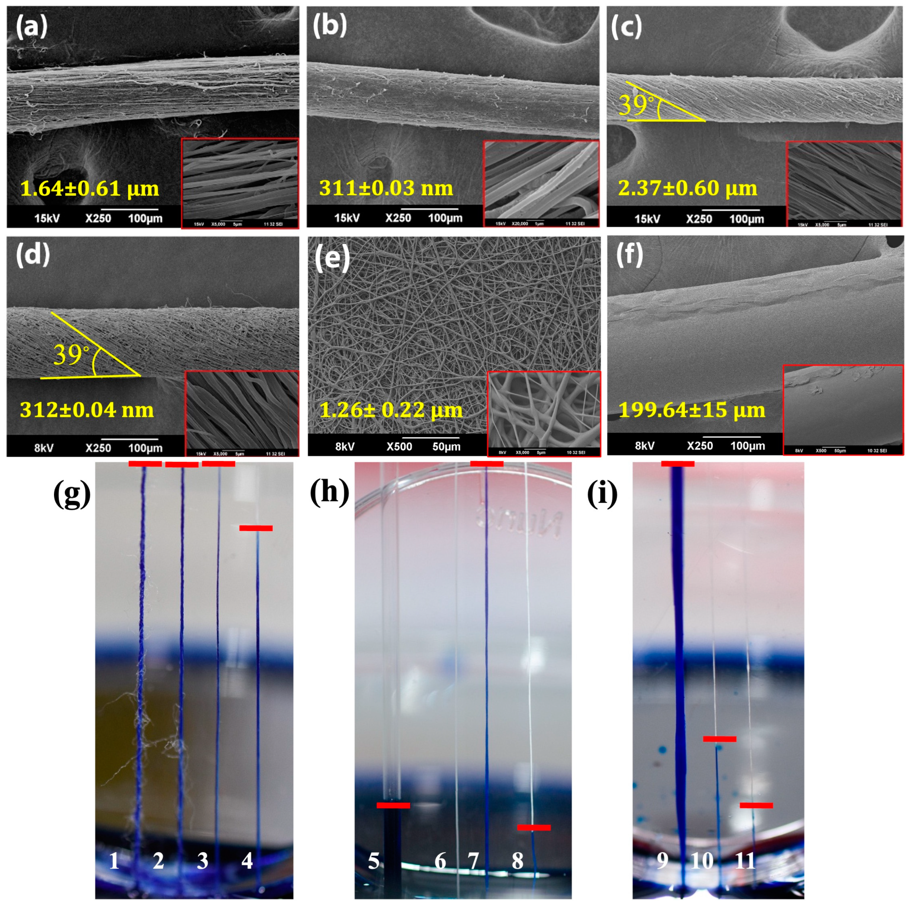
Interaction and adhesion of both bacterial and mammalian cells with yarns of different materials, fiber diameter, and orientation were studied. Continuous fibrous yarns of PCL and PLLA were fabricated by a modified electrospinning process reported earlier by our group [25]. Nano- and microfibrous yarns of PCL were obtained without any fiber fusion and bead formation, which are the usual imperfections associated with electrospun fibers. The surface topography and fiber diameter of PCL yarns were confirmed by SEM (Figure 1a–f). Post-processing treatment (stretching and/or twisting) provided the desired fiber orientation. Aligned yarns of PCL nano- and microfibers with diameters 159.44 ± 38 µm and 191.25 ± 79 µm were fabricated by the post-processing technique of stretching the yarns by 200 and 300%, respectively. Figure 1a,b revealed aligned micro- and nanofibrous yarns of PCL with an average fiber size of 1.6 ± 0.61 μm and 311 ± 0.04 nm, respectively.
Similarly, longitudinally aligned PLLA yarns were developed by the process of heat-stretching, wherein the yarns were heated above the glass transition temperature (up to 120 °C) along with stretching (Figure S1a). Elongated yarns resulted in fiber alignment that facilitated the formation of a greater number of channels among the fibers. Conversely, the twisting of yarns resulted in closer material packing and, thereby, higher fiber density per cross-sectional area, leading to the closure of channels identified from the SEM micrographs. The angle of fiber twist in micro- and nano-PCL yarns was ~39° (Figure 1c,d). The electrospun mat of PCL (Figure 1e) fabricated by conventional electrospinning displayed numerous interconnected pores created by the random orientation of fibers with a diameter of 1.26 ± 0.22 μm. The melt-extruded PCL monofilament had an average diameter of 199 ± 15 µm (Figure 1f), which is approximately similar to the dimensions of micro/nanoyarns of PCL and PLLA. Similarly, the morphological characterization of PET fiber and cotton thread was also evaluated by SEM (Figure S1a–c in Supplementary).
3.1. Wettability of Fibrous Yarns
In general, wetting and spreading of water drops on a yarn surface is caused by wicking due to the presence of a multitude of channels present among the fibers [39]. Wicking is attributed to material type, fiber roughness and orientation, channel number, and fibers per cross-sectional area of the yarn [40,41,42,43,44]. The primary objective of this study was to examine the impact of fiber size and orientation on its wicking pattern. To assess the wicking behavior, experiments were performed using vertically mounted yarns immersed in a dye reservoir. It was noticed that fiber size and orientation influence the movement of liquid through the yarn structure. Wicking in PCL yarns of different fiber diameters and orientations was compared with other control materials (PLLA, PET, cotton, and glass capillary tube) after 30 min, as shown in Figure 1g–i. All the polymeric yarns showed a higher capillary effect compared to a capillary tube of similar bore size (Figure 1g). Interestingly, PCL yarn composed of micron-sized fibers exhibited a higher capillary effect than nanofibers, as shown in Figure 1h (7 and 8). As expected, the monofilament displayed no capillary effect due to the absence of channels in its structure (Figure 1h-6). The wicking behavior in PCL micro-sized fibers follows the Washburn equation, wherein the penetration length or wicking height increases with increased spacing between the fibers (i.e., channel width) [45]. Thus, the presence of wider channels between the micron-sized fibers with a large fiber-to-fiber distance yielded increased wicking height, compared to nanofibrous yarns with a high packing density of fibers rendering narrow channels [46]. A similar observation was found in a study in which a surge of wicking was observed in PET fibers of a 6 μm diameter compared to PAN fibers of a 600 nm diameter [47]. Likewise, studies on ‘nanowicking’ in carbon nanotube (CNT) and metallic NW arrays [48] showed that larger diameter tubes/wires presented the largest wicking length, being maximum at an optimal surface density of tubes. Figure 1i represents PCL fibers with different orientations, viz., random, aligned, and twisted. Of note, randomly oriented fibers present in a non-woven electrospun mat demonstrated higher wicking due to the presence of numerous interconnected pores, which promoted the permeation of the dye into the void space (Figure 1i-9) [49]. Moreover, aligned fibers showed a relatively higher capillary effect than yarns with twisted fibers (Figure 1i-10,i-11). The packing density of fibers is higher in twisted yarns than in aligned yarns, which leads to tighter packing and closure of channels between the fibers, thereby attenuating the wicking effect.
3.2. Quantification of Adherent Bacteria on Fibrous Yarns
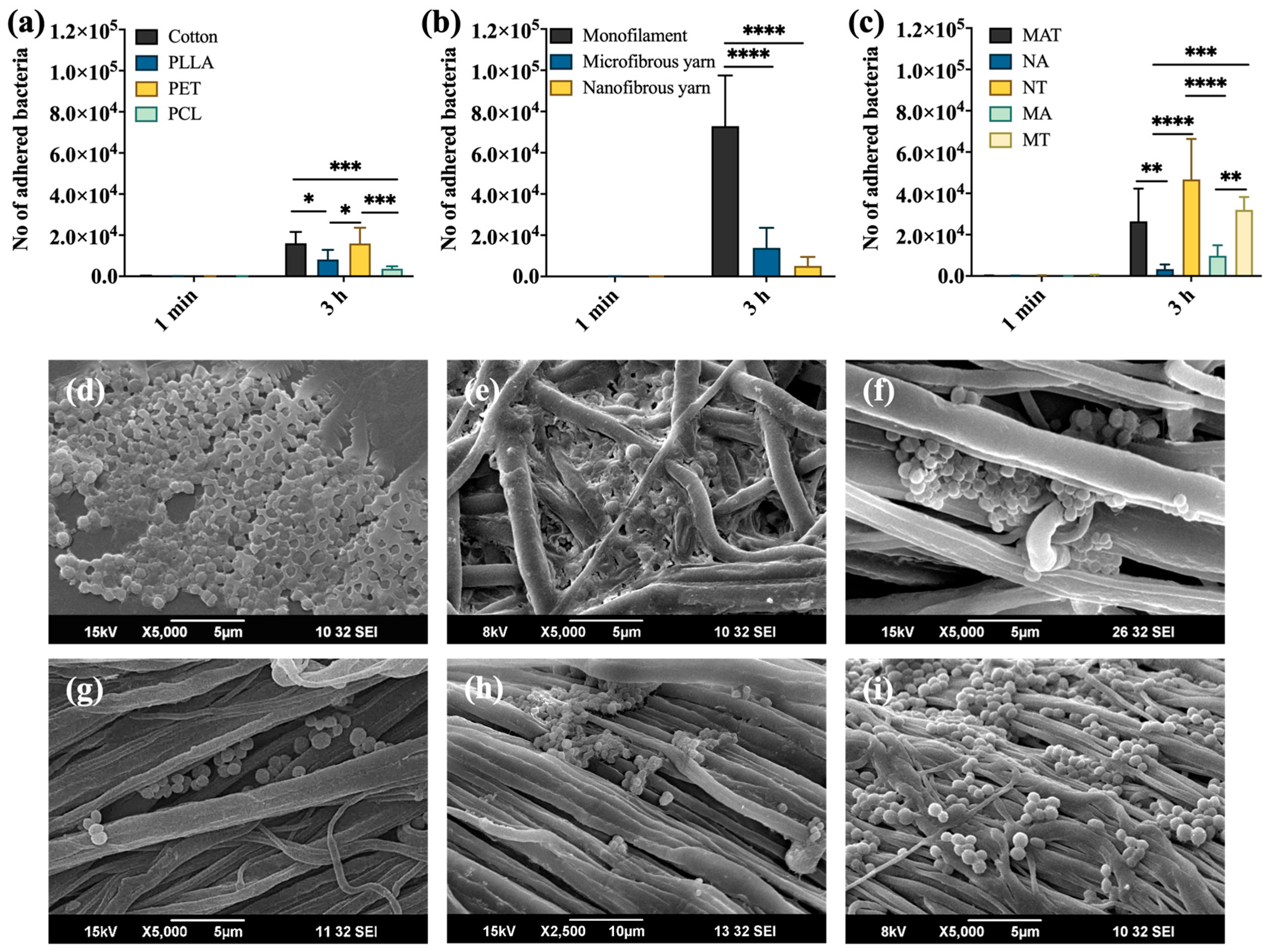
At the early time point (t = 1 min), no significant attachment of bacteria was noted on the materials, even though there were a few adherent bacteria in the control materials, such as cotton and the medical textile, PET. With increasing time (3 h), a significant adhesion of S. aureus was observed on cotton and PET, attributed to their higher capillary effect (Figure S2a–d in Supplementary). Among yarn materials, PCL showed the least affinity for bacterial adhesion. Hence, PCL yarns were selected for further experiments with prokaryotes, wherein the influence of fiber diameter and orientation in yarns were assessed. PCL nanoaligned yarn had the least adhesion of S. aureus in comparison to PCL microaligned yarn and monofilament (Figure 2b). This decreased colonization of spherically shaped bacteria on nanoyarn may be attributed to two reasons: (i) lower wicking and (ii) larger bacteria size (0.5 µm) compared to its fiber diameter (~300 nm). This would result in lower adhesion points for the bacteria to attach onto the fiber surface [50,51] (Figure 2g). This observation correlates well with the SEM images (Figure 2d,f,g), wherein the bacterial adhesion was found to be in the following order: PCL monofilament > PCL microaligned yarn > PCL nanoaligned yarn. Interestingly, bacterial adhesion on twisted yarns (both micro- and nano-) was higher compared to the aligned forms (Figure 2c). This observation was more pronounced in nanotwisted yarns compared to their microtwisted form (Figure 2h,i). The twisting of nanofibrous yarn resulted in a more compactly packed construct with minimal void space than any other form, owing to its small fiber size. We hypothesize that the dense packing of fibers facilitates the bacteria’s adherence to multiple contact points on adjacent fibers, promoting bacterial colony formation (Figure 2i). This effect was superior for monofilaments, which promoted high bacterial colony formation (~6.5 × 10⁴ CFU/mL/mm2), as can be seen from Figure 2b,d.
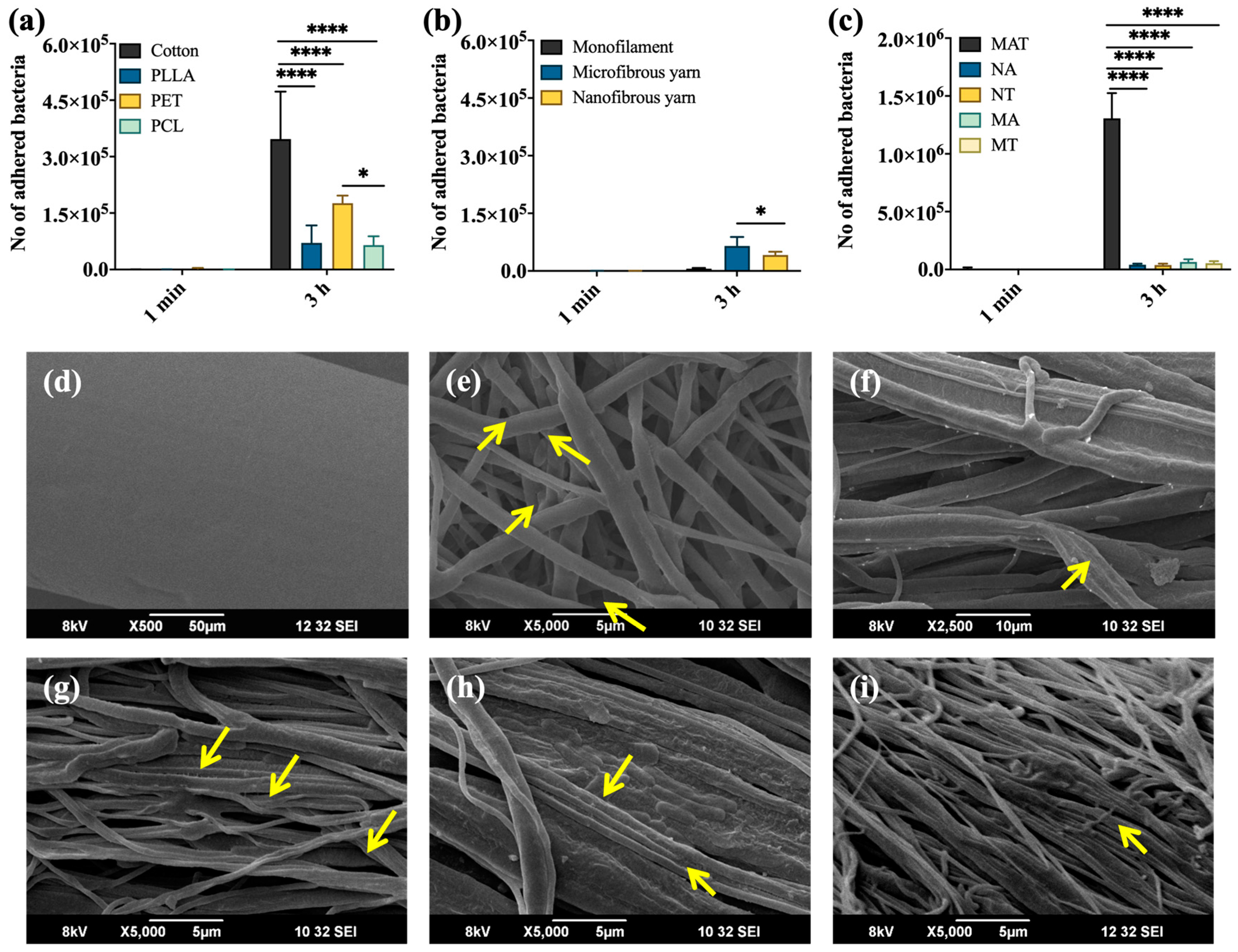
The CFU (expressed as count/mL per unit area) of adherent E. coli on various samples is depicted in Figure 3 for two time points (0 and 3 h). PCL and PLLA yarns showed significantly lower adhesion of E. coli (Figure 3a) compared to other control materials, much similar to that seen with S. aureus (Figure S3a–c, Supplementary). The low adhesion of Gram-positive and -negative bacteria on PCL may be due to its unique material property, which demands further research. A significantly low adhesion of E. coli was noted on nanofibrous yarn (Figure 3b) relative to microfibrous yarn. Likewise, nano- and microaligned fibrous yarns revealed a remarkably low bacterial adhesion in comparison to the randomly aligned electrospun mat (Figure 3c). Amongst all samples tested, the random non-woven electrospun mat had the highest capillary action (Figure 1i-9), which, in general, possesses an enhanced contact surface area for bacteria to interact with the material. These findings were similar to the adhesion trend of S. aureus. Surprisingly, E. coli attachment on PCL monofilament was negligibly less, when assessed quantitatively and qualitatively, in comparison to S. aureus. This can be ascribed to the differences in the mechanism of attachment and colonization of different bacterial strains [52]. Thus, from the bacterial studies, it can be summarized that the electrospun mat with random fiber orientation promoted bacterial attachment, whereas the aligned fibrous structures, such as nanoaligned fibrous yarn, retarded its adhesion.
3.3. Quantification of Mammalian Cell Attachment and Viability
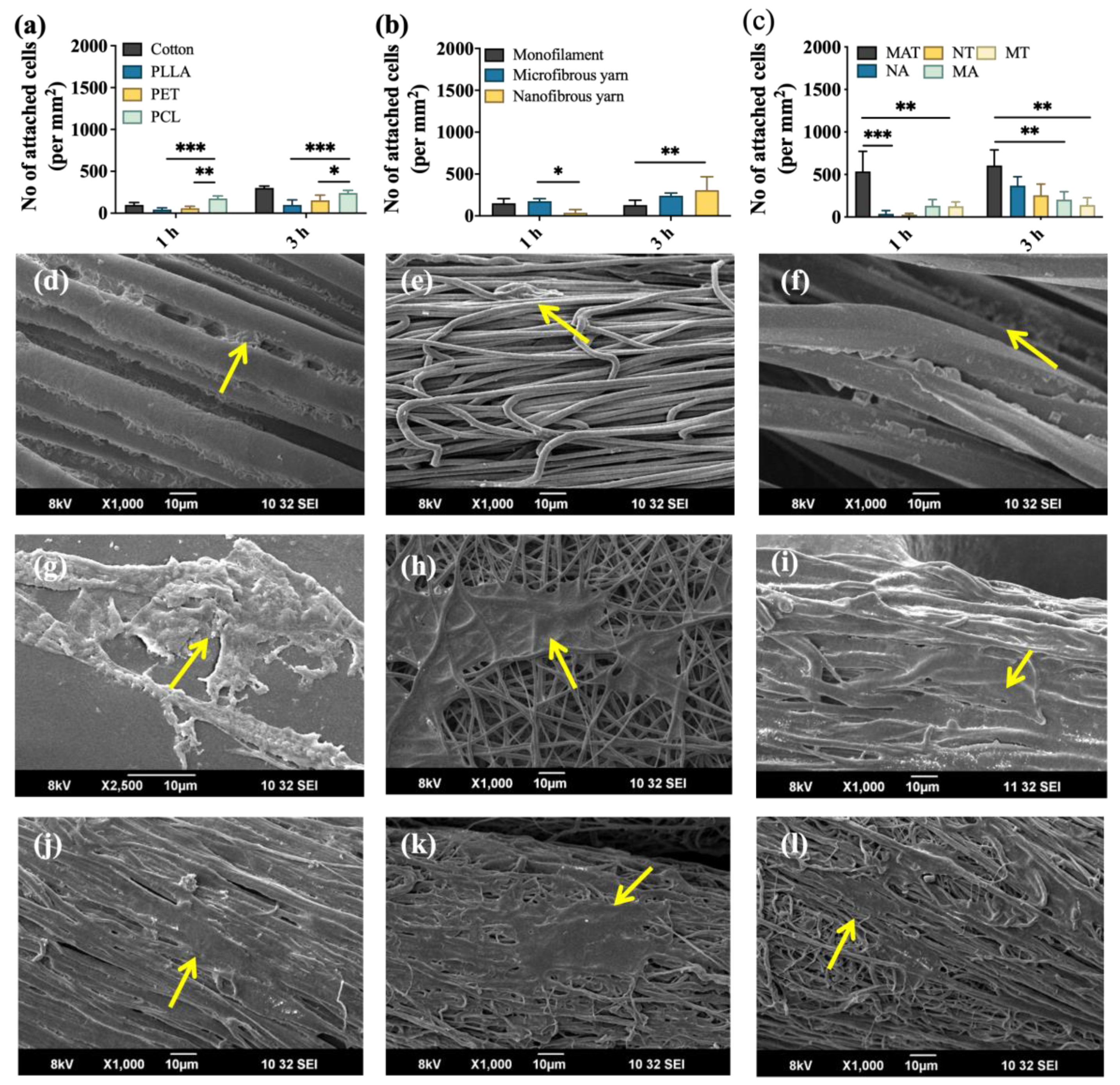
The initial interaction and attachment of MSCs on fibers of polymeric yarns were quantified using Alamar blue assay. It was noticed that the attachment of cells was seen in all fibrous materials, including the control materials, in the first hour of incubation (Figure 4a). As time progressed, an increase in cell number was observed in all the samples. Cotton also showed a relatively high number of adherent cells, perhaps owing to its highest capillary effect, which facilitated more interfacial interaction.
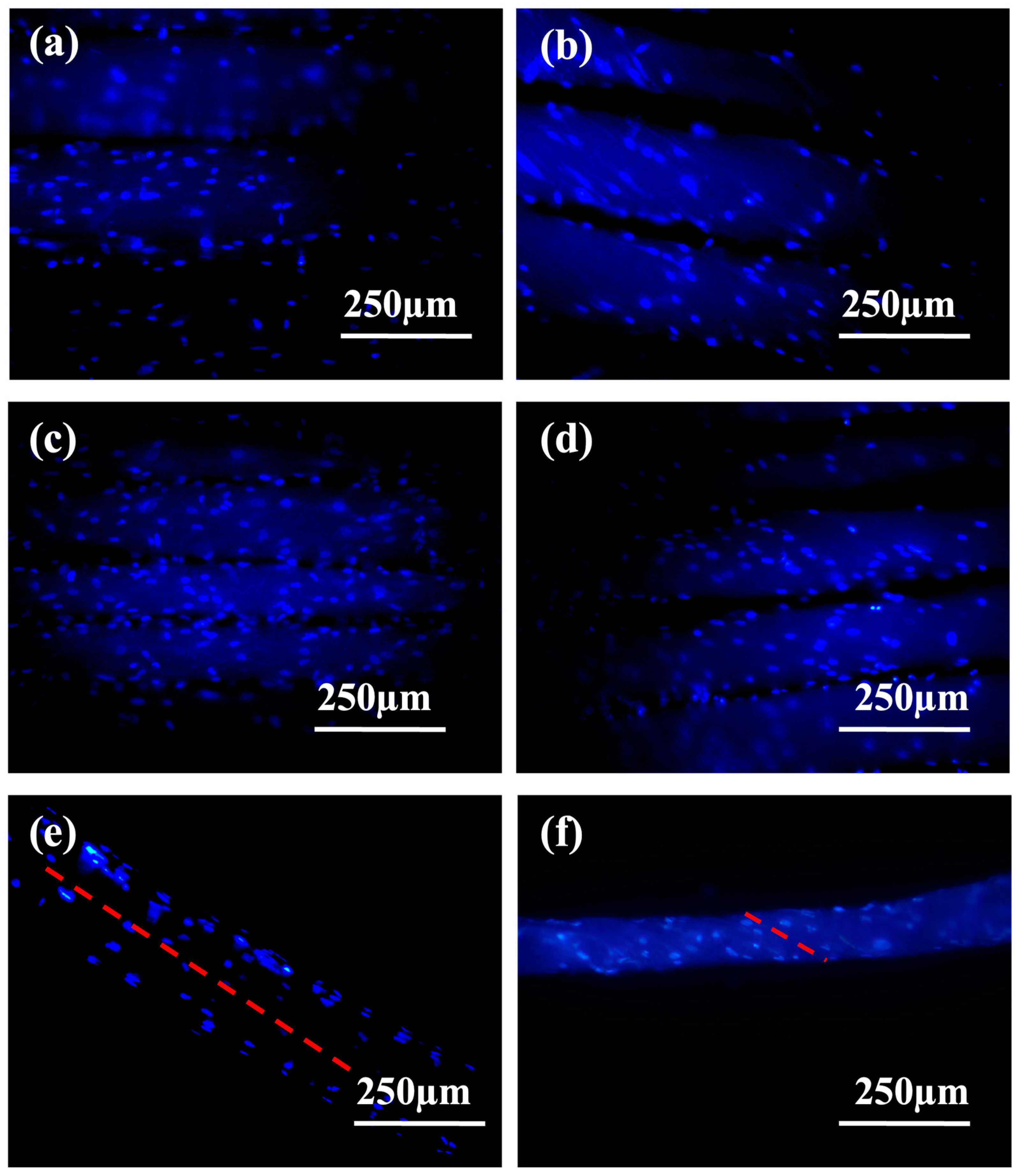
With varying fiber diameter, early adhesion (t = 1 h) of MSCs on PCL microfiber was relatively higher compared to nanoyarn, which can be substantiated by the instantaneous wetting via capillary action, resulting in enhanced retention of cells on the material, as shown in Figure 4b. At a longer time point, the cellular attachment was comparable for both micro- and nanoyarns. On comparing yarns with different fiber orientations (Figure 4c), the random fibers of the electrospun mat had greater attachment of MSCs initially, owing to its high wicking rate (Figure 1i-9), followed by aligned and twisted yarns. The electrospun mat exhibited superior cell attachment and retention at all time points, which may be attributed to its higher rate of capillary action with interconnected pores, unlike the electrospun yarn. Cell attachment on fibrous yarns was also confirmed qualitatively by SEM and fluorescence microscopy, supporting the quantitative observations. SEM micrographs of cell attachment are shown in Figure 4d–l, from which a greater affinity for cell spreading was observed on PCL fibrous yarns compared to monofilament, where the cells attained a rounded morphology (Figure 4g). Conversely, electrospun mat and nanoaligned yarns were found to have an effective spreading of MSCs on the fiber surface. To confirm and visualize cell attachment with respect to the orientation of fibers, DAPI staining was carried out, followed by fluorescence imaging, as in Figure 5 and Figure S4. The attachment of MSCs was more or less similar in all materials at a time point of 3 h. Cells were mostly attached along the orientation of alignment and twist in the fibers of PCL fibrous yarns (Figure 5e,f). The mechanism of cell orientation along the fibers can be discerned by applying geometric potential theory, where the spreading length of the cell follows a negative correlation to the distance between two fibers [53]. In this perspective, the orientation of MSCs along the nanotwisted fibers was more prominent (Figure 5f), as the distance between two fibers is less in twisted yarn, whereas the fiber-to-fiber distance is high in the aligned ones.
3.4. Enhanced Capillary Rise of MSCs in PCL Fibrous Yarn
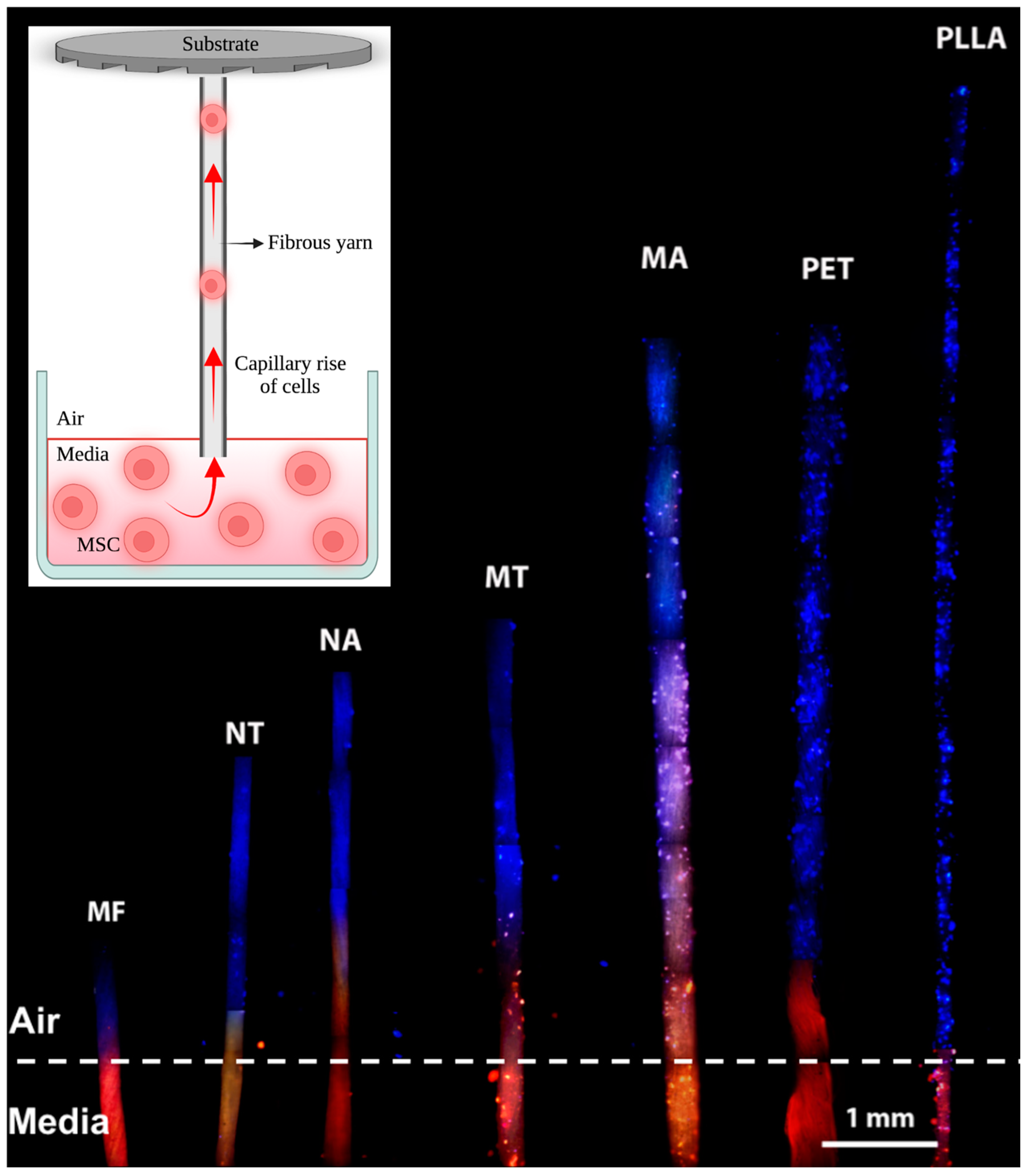
The capillary action of MSCs through polymeric fibrous yarns was studied for the first time by employing a new experimental method, as depicted in the inset of Figure 6. Fluorescence emission from rhodamine was used to confirm the air–media interface of the yarn, which was immersed in the tissue culture plate seeded with MSCs. Nuclear staining by DAPI revealed the presence of MSCs in the yarns after 6 h of incubation. Capillary uptake of MSCs was higher in PCL microaligned fibers, as depicted in Figure 6. Similarly, PLLA and PET yarns also showed an increase in MSCs throughout the length of the yarn. These data were in concurrence with the observations from the dye-wicking experiment. The fiber properties of these yarns complied with the Washburn equation [45] and resulted in enhanced wicking of cells due to their wider channels. On the contrary, the fibers of PCL nanoaligned yarn being closely packed rendered a narrow channel width, and, hence, the uptake of cells mediated by capillary action was limited. The capillary action of MSCs was not noticed in PCL monofilament and twisted fibers due to the absence of channels and, hence, demonstrated minimal cell attachment.
Thus, to summarize, cellular (MSCs) and bacterial adherence were significantly higher for randomly oriented fibers in the PCL electrospun mat due to its higher capillary effect, implying that scaffolds with random fiber orientation confer a conducive environment for the growth of pathogenic microbes. In contrast, nanoscale fibers present in the aligned PCL yarns selectively promoted cellular attachment with a low bacterial affinity, compared with twisted yarn and electrospun mat. Our study provides insight into the significance of fiber properties on their interfacial interaction with cells and bacteria by probing the mechanism of wicking patterns. However, further studies are necessary to comprehend the influence of hydrophilic/hydrophobic properties of the material used, fiber roughness, and channel size between fibers in a yarn on the wicking pattern. Altogether, high mechanical strength coupled with the superior interaction of mammalian cells can facilitate the use of electrospun yarn for developing woven or knitted nanotextiles for biomedical applications.
4. Conclusions
The study emphasizes the significance of fiber geometry and arrangement in polymeric yarns to mitigate microbial infection and subsequent biofilm formation, while also improving the adhesion of eukaryotic cells. Our study shows that by tailoring the architecture and diameter of fibers in yarns, undesired bacterial adhesion can be reduced without the addition of antimicrobial agents or other surface modification techniques. Additionally, the diameter and fiber configuration of yarns were found to have a noticeable effect on mesenchymal stem cell attachment. Among the various materials tested, nanoaligned PCL yarns were particularly effective in promoting eukaryotic cell adhesion while also providing antiadhesive surfaces for bacteria, thus reducing the risk of infection and biofilm formation. Therefore, fiber properties are crucial design considerations for fabricating medical textiles to control implant-related infections.
Supplementary Materials
The following supporting information can be downloaded at: https://www.mdpi.com/article/10.3390/applbiosci2040033/s1, Figure S1. SEM micrographs of polymeric yarns, Figure S2. SEM micrographs show S. aureus adhesion, Figure S3. SEM micrographs of E. coli adhesion, Figure S4. DAPI nuclear staining exhibiting cell attachment.
Author Contributions
Conceptualization, H.M.B., J.J., R.B. and D.M.; methodology, H.M.B., J.J. and M.K.S.; software, H.M.B.; validation, H.M.B., J.J. and M.K.S.; formal analysis, H.M.B.; investigation, H.M.B., J.J., M.K.S., R.B. and D.M.; resources, R.B. and D.M.; data curation, H.M.B.; writing—original draft preparation, H.M.B.; writing—review and editing, H.M.B., J.J., M.K.S., R.B. and D.M.; visualization, H.M.B., J.J. and M.K.S.; supervision, R.B. and D.M.; project administration, R.B. and D.M.; funding acquisition, R.B. and D.M.; All authors have read and agreed to the published version of the manuscript.
Funding
This research received no external funding.
Institutional Review Board Statement
The animal study protocol was approved by the Institutional Ethics Committee of Amrita Institute of Medical Sciences, Kochi, Kerala, India (protocol code IEC-AIMS-2018-NANO-100, 20-06-2018).
Informed Consent Statement
Not Applicable.
Data Availability Statement
Data are contained within the article.
Acknowledgments
Authors acknowledge the financial support provided by the Department of Science and Technology, Government of India, and Amrita Vishwa Vidyapeetham for all infrastructure support. The authors thank Sajin P Ravi and Dennis Mathew for help with SEM imaging. Helna Mary Baby was financially supported by the M.Tech Nanomedical project grant (Ref No: SR/NM/PG-01/2015, Department of Science and Technology, Government of India).
Conflicts of Interest
The authors declare no conflict of interest.
Abbreviations
PLLA—Poly-L-lactic acid, PET—polyethylene terephthalate, PCL—poly-€-caprolactone, MAT—PCL 2D non-woven electrospun mat, MA—PCL microaligned yarn, MT—PCL microtwisted yarn, NA—PCL nanoaligned yarn, NT—PCL nanotwisted yarn.
References
- Zhang, Y.; Lim, C.T.; Ramakrishna, S.; Huang, Z.-M. Recent Development of Polymer Nanofibers for Biomedical and Biotechnological Applications. J. Mater. Sci. Mater. Med. 2005, 16, 933–946. [Google Scholar] [CrossRef] [PubMed]
- Wei, G.; Ma, P.X. Nanostructured Biomaterials for Regeneration. Adv. Funct. Mater. 2008, 18, 3566–3582. [Google Scholar] [CrossRef] [PubMed]
- Stocco, T.D.; Bassous, N.J.; Zhao, S.; Granato, A.E.C.; Webster, T.J.; Lobo, A.O. Nanofibrous Scaffolds for Biomedical Applications. Nanoscale 2018, 10, 12228–12255. [Google Scholar] [CrossRef] [PubMed]
- Sarviya, N.; Mahanta, U.; Dart, A.; Giri, J.; Deshpande, A.S.; Khandelwal, M.; Bhave, M.; Kingshott, P. Biocompatible and Antimicrobial Multilayer Fibrous Polymeric Wound Dressing with Optimally Embedded Silver Nanoparticles. Appl. Surf. Sci. 2023, 612, 155799. [Google Scholar] [CrossRef]
- Meng, S.; Wu, H.; Xiao, D.; Lan, S.; Dong, A. Recent Advances in Bacterial Cellulose-Based Antibacterial Composites for Infected Wound Therapy. In Carbohydrate Polymers; Elsevier Ltd.: Amsterdam, The Netherlands, 2023. [Google Scholar] [CrossRef]
- Karbowniczek, J.E.; Berniak, K.; Knapczyk-Korczak, J.; Williams, G.; Bryant, J.A.; Nikoi, N.D.; Banzhaf, M.; de Cogan, F.; Stachewicz, U. Strategies of Nanoparticles Integration in Polymer Fibers to Achieve Antibacterial Effect and Enhance Cell Proliferation with Collagen Production in Tissue Engineering Scaffolds. J. Colloid Interface Sci. 2023, 650, 1371–1381. [Google Scholar] [CrossRef]
- McHugh, K.J.; Tao, S.L.; Saint-Geniez, M. A Novel Porous Scaffold Fabrication Technique for Epithelial and Endothelial Tissue Engineering. J. Mater. Sci. Mater. Med. 2013, 24, 1659–1670. [Google Scholar] [CrossRef]
- Reneker, D.H.; Chun, I. Nanometre Diameter Fibres of Polymer, Produced by Electrospinning. Nanotechnology 1996, 7, 216–223. [Google Scholar] [CrossRef]
- Kim, J.I.; Kim, J.Y.; Park, C.H. Fabrication of Transparent Hemispherical 3D Nanofibrous Scaffolds with Radially Aligned Patterns via a Novel Electrospinning Method. Sci. Rep. 2018, 8, 3424. [Google Scholar] [CrossRef]
- Kim, J.I.; Hwang, T.I.; Aguilar, L.E.; Park, C.H.; Kim, C.S. A Controlled Design of Aligned and Random Nanofibers for 3D Bi-Functionalized Nerve Conduits Fabricated via a Novel Electrospinning Set-Up. Sci. Rep. 2016, 6, 23761. [Google Scholar] [CrossRef]
- Su, Y.; Toftdal, M.S.; Le Friec, A.; Dong, M.; Han, X.; Chen, M. 3D Electrospun Synthetic Extracellular Matrix for Tissue Regeneration. Small Sci. 2021, 1, 2100003. [Google Scholar] [CrossRef]
- Keirouz, A.; Chung, M.; Kwon, J.; Fortunato, G.; Radacsi, N. 2D and 3D Electrospinning Technologies for the Fabrication of Nanofibrous Scaffolds for Skin Tissue Engineering: A Review. In Wiley Interdisciplinary Reviews: Nanomedicine and Nanobiotechnology; Wiley-Blackwell: Hoboken, NJ, USA, 2020. [Google Scholar] [CrossRef]
- Bongiovanni Abel, S.; Montini Ballarin, F.; Abraham, G.A. Combination of Electrospinning with Other Techniques for the Fabrication of 3D Polymeric and Composite Nanofibrous Scaffolds with Improved Cellular Interactions. Nanotechnology 2020, 31, 172002. [Google Scholar] [CrossRef] [PubMed]
- Liu, G.-F.; Zhang, D.; Feng, C.-L. Control of Three-Dimensional Cell Adhesion by the Chirality of Nanofibers in Hydrogels. Angew. Chem. Int. Ed. Engl. 2014, 53, 7789–7793. [Google Scholar] [CrossRef] [PubMed]
- Ku, S.H.; Park, C.B. Human Endothelial Cell Growth on Mussel-Inspired Nanofiber Scaffold for Vascular Tissue Engineering. Biomaterials 2010, 31, 9431–9437. [Google Scholar] [CrossRef] [PubMed]
- Lee, Y.-S.; Livingston Arinzeh, T. Electrospun Nanofibrous Materials for Neural Tissue Engineering. Polymers 2011, 3, 413. [Google Scholar] [CrossRef]
- Saino, E.; Focarete, M.L.; Gualandi, C.; Emanuele, E.; Cornaglia, A.I.; Imbriani, M.; Visai, L. Effect of Electrospun Fiber Diameter and Alignment on Macrophage Activation and Secretion of Proinflammatory Cytokines and Chemokines. Biomacromolecules 2011, 12, 1900–1911. [Google Scholar] [CrossRef]
- Bashur, C.A.; Shaffer, R.D.; Dahlgren, L.A.; Guelcher, S.A.; Goldstein, A.S. Effect of Fiber Diameter and Alignment of Electrospun Polyurethane Meshes on Mesenchymal Progenitor Cells. Tissue Eng. Part A 2009, 15, 2435–2445. [Google Scholar] [CrossRef]
- Nakayama, K. In Vitro Biofabrication of Tissues and Organs. In Biofabrication: Micro- and Nano-fabrication, Printing, Patterning and Assemblies; William Andrew Publishing: Norwich, NY, USA, 2013; pp. 1–21. [Google Scholar] [CrossRef]
- Kargar, M.; Wang, J.; Nain, A.S.; Behkam, B. Controlling Bacterial Adhesion to Surfaces Using Topographical Cues: A Study of the Interaction of Pseudomonas Aeruginosa with Nanofiber-Textured Surfaces. Soft Matter 2012, 8, 10254–10259. [Google Scholar] [CrossRef]
- Abrigo, M.; Kingshott, P.; McArthur, S.L. Electrospun Polystyrene Fiber Diameter Influencing Bacterial Attachment, Proliferation, and Growth. ACS Appl. Mater. Interfaces 2015, 7, 7644–7652. [Google Scholar] [CrossRef]
- Nisbet, D.R.; Forsythe, J.S.; Shen, W.; Finkelstein, D.I.; Horne, M.K. Review Paper: A Review of the Cellular Response on Electrospun Nanofibers for Tissue Engineering. J. Biomater. Appl. 2009, 24, 7–29. [Google Scholar] [CrossRef]
- Tian, F.; Hosseinkhani, H.; Hosseinkhani, M.; Khademhosseini, A.; Yokoyama, Y.; Estrada, G.G.; Kobayashi, H. Quantitative Analysis of Cell Adhesion on Aligned Micro- and Nanofibers. J. Biomed. Mater. Res. A 2008, 84, 291–299. [Google Scholar] [CrossRef]
- Mortimer, C.; Burke, L.; Wright, C. Microbial Interactions with Nanostructures and Their Importance for the Development of Electrospun Nanofibrous Materials Used in Regenerative Medicine and Filtration. J. Microb. Biochem. Technol. 2016, 8, 195–201. [Google Scholar] [CrossRef]
- Joseph, J.; Nair, S.V.; Menon, D. Integrating Substrateless Electrospinning with Textile Technology for Creating Biodegradable Three-Dimensional Structures. Nano Lett. 2015, 15, 5420–5426. [Google Scholar] [CrossRef] [PubMed]
- Padmakumar, S.; Joseph, J.; Neppalli, M.H.; Mathew, S.E.; Nair, S.V.; Shankarappa, S.A.; Menon, D. Electrospun Polymeric Core–Sheath Yarns as Drug Eluting Surgical Sutures. ACS Appl. Mater. Interfaces 2016, 8, 6925–6934. [Google Scholar] [CrossRef]
- Padmakumar, S.; Paul-Prasanth, B.; Pavithran, K.; Vijaykumar, D.K.; Rajanbabu, A.; Sivanarayanan, T.B.; Kadakia, E.; Amiji, M.M.; Nair, S.V.; Menon, D. Long-Term Drug Delivery Using Implantable Electrospun Woven Polymeric Nanotextiles. Nanomedicine 2019, 15, 274–284. [Google Scholar] [CrossRef] [PubMed]
- Wu, Y.; Wang, L.; Guo, B.; Ma, P.X. Interwoven Aligned Conductive Nanofiber Yarn/Hydrogel Composite Scaffolds for Engineered 3D Cardiac Anisotropy. ACS Nano 2017, 11, 5646–5659. [Google Scholar] [CrossRef]
- Tan, G.Z.; Zhou, Y. Tunable 3D Nanofiber Architecture of Polycaprolactone by Divergence Electrospinning for Potential Tissue Engineering Applications. Nanomicro Lett. 2018, 10, 73. [Google Scholar] [CrossRef]
- Joseph, J.; Krishnan, A.G.; Cherian, A.M.; Rajagopalan, B.; Jose, R.; Varma, P.; Maniyal, V.; Balakrishnan, S.; Nair, S.V.; Menon, D. Transforming Nanofibers into Woven Nanotextiles for Vascular Application. ACS Appl. Mater. Interfaces 2018, 10, 19449–19458. [Google Scholar] [CrossRef]
- Babu, R.; Joseph, J.; Sathy, B.N.; Nair, S.V.; Varma, P.K.; Menon, D. Design, Development, and Evaluation of an Interwoven Electrospun Nanotextile Vascular Patch. Macromol. Mater. Eng. 2021, 306, 2100359. [Google Scholar] [CrossRef]
- Yang, J.; Xu, L. Electrospun Nanofiber Membranes with Various Structures for Wound Dressing. Materials 2023, 16, 6021. [Google Scholar] [CrossRef]
- Tanaka, T.; Tanaka, R.; Ogawa, Y.; Takagi, Y.; Asakura, T. Development of Small-Diameter Polyester Vascular Grafts Coated with Silk Fibroin Sponge. Organogenesis 2020, 16, 1–13. [Google Scholar] [CrossRef]
- Farah, S.; Anderson, D.G.; Langer, R. Physical and Mechanical Properties of PLA, and Their Functions in Widespread Applications—A Comprehensive Review. In Advanced Drug Delivery Reviews; Elsevier B.V.: Amsterdam, The Netherlands, 2016; pp. 367–392. [Google Scholar] [CrossRef]
- Kozaniti, F.K.; Manara, A.E.; Kostopoulos, V.; Mallis, P.; Michalopoulos, E.; Polyzos, D.; Deligianni, D.D.; Portan, D.V. Computational and Experimental Investigation of the Combined Effect of Various 3D Scaffolds and Bioreactor Stimulation on Human Cells’ Feedback. Appl. Biosci. 2023, 2, 249–277. [Google Scholar] [CrossRef]
- Vaishya, R.; Agarwal, A.K.; Tiwari, M.; Vaish, A.; Vijay, V.; Nigam, Y. Medical Textiles in Orthopedics: An Overview. J. Clin. Orthop. Trauma 2018, 9, S26–S33. [Google Scholar] [CrossRef] [PubMed]
- Arciola, C.R.; Campoccia, D.; Montanaro, L. Implant Infections: Adhesion, Biofilm Formation and Immune Evasion. Nat. Rev. Microbiol 2018, 16, 397–409. [Google Scholar] [CrossRef] [PubMed]
- Herigstad, B.; Hamilton, M.; Heersink, J. How to Optimize the Drop Plate Method for Enumerating Bacteria. J. Microbiol. Methods 2001, 44, 121–129. [Google Scholar] [CrossRef] [PubMed]
- Patnaik, A.; Rengasamy, R.S.; Kothari, V.K.; Ghosh, A. Wetting and Wicking in Fibrous Materials. Text. Prog. 2006, 38, 1–105. [Google Scholar] [CrossRef]
- Hollies, N.R.S.; Kaessinger, M.M.; Bogaty, H. Water Transport Mechanisms in Textile Materials1 Part I: The Role of Yarn Roughness in Capillary-Type Penetration. Text. Res. J. 1956, 26, 829–835. [Google Scholar] [CrossRef]
- Lord, P.R. A Comparison of the Performance of Open-End and Ring Spun Yarns in Terry Toweling. Text. Res. J. 1974, 44, 516–522. [Google Scholar] [CrossRef]
- Chattopadhyay, R.; Chauhan, A. Wicking Behavior of Compact and Ring Spun Yarns and Fabrics. Melliand Int. 2005, 11, 25–30. [Google Scholar]
- Sengupta, A.K.; Sreenivasa Murthy, H.V. Wicking in Ring-Spun Vis-a-Vis Rotor-Spun Yarns. Indian J. Text. Res. 1985, 10, 155–157. [Google Scholar]
- Staples, T.; Shaffer, D. Wicking Flow in Irregular Capillaries. Colloids Surf A Physicochem. Eng. Asp. 2002, 204, 239–250. [Google Scholar] [CrossRef]
- Liu, M.; Wu, J.; Gan, Y.; Hanaor, D.A.H.; Chen, C.Q. Evaporation Limited Radial Capillary Penetration in Porous Media. Langmuir 2016, 32, 9899–9904. [Google Scholar] [CrossRef] [PubMed]
- Kriel, F.; Sedev, R.; Priest, C. Capillary Filling of Nanoscale Channels and Surface Structure. Isr. J. Chem. 2014, 54, 1519–1532. [Google Scholar] [CrossRef]
- Tsai, C.-C.; Kornev, K.G. Characterization of Permeability of Electrospun Yarns. Langmuir 2013, 29, 10596–10602. [Google Scholar] [CrossRef]
- Chen, Q.; Huang, Y. Effect of Low Wick Permeability on Transient and Steady-State Performance of Heat Pipes. Heat Transf. Res. 2018, 50, 1319–1332. [Google Scholar] [CrossRef]
- Sengupta, A.K.; Kothari, V.K.; Rengasamy, R.S. Wicking Behaviour of Air-Jet Textured Yarns. Indian J. Fibre Text Res. 1991, 16, 123–127. [Google Scholar]
- Hsu, L.C.; Fang, J.; Borca-Tasciuc, D.A.; Worobo, R.W.; Moraru, C.I. Effect of Micro- and Nanoscale Topography on the Adhesion of Bacterial Cells to Solid Surfaces. Appl. Environ. Microbiol. 2013, 79, 2703–2712. [Google Scholar] [CrossRef]
- Shellenberger, K.; Logan, B.E. Effect of Molecular Scale Roughness of Glass Beads on Colloidal and Bacterial Deposition. Environ. Sci. Technol. 2002, 36, 184–189. [Google Scholar] [CrossRef]
- Tuson, H.H.; Weibel, D.B. Bacteria–Surface Interactions. Soft Matter 2013, 9, 4368–4380. [Google Scholar] [CrossRef]
- Fan, J.; Zhang, Y.; Liu, Y.; Wang, Y.; Cao, F.; Yang, Q.; Tian, F. Explanation of the Cell Orientation in a Nanofiber Membrane by the Geometric Potential Theory. Results Phys. 2019, 15, 102537. [Google Scholar] [CrossRef]
Figure 1.
Morphological evaluation of fibrous yarns by SEM imaging. (a–d) PCL microfibrous and nanofibrous yarns with (a,b) aligned fibers and (c,d) twisted fibers, respectively; (e) randomly oriented fibers in electrospun PCL mat and (f) PCL monofilament. Scale bars of inset figures: (a) 5 μm, (b) 1 μm, (c) 5 μm, (d) 5 μm, (e) 5 μm, and (f) 50 μm. (g–i) Wicking of dye after 30 min in dye reservoir; (g) microyarns of different materials such as (1) cotton, (2) PET, (3) PLLA, and (4) PCL; (h) yarns with varying fiber diameter: (5) glass capillary tube, (6) PCL monofilament, (7) PCL microfibrous yarn, and (8) nanofibrous yarn; (i) different fiber orientations: (9) electrospun PCL mat, (10) aligned, and (11) twisted PCL nanofibrous yarns. Red line denotes the height to which the dye is wicked.

Figure 2.
Number of adhered S. aureus on (a) different materials, (b) PCL fibers of different diameters, and (c) PCL fibers of different orientations expressed in CFU (count per ml per unit area in mm2) at t = 0 and 3 h. * p < 0.05, ** p < 0.01, *** p < 0.0005, and **** p < 0.0001. p values were determined using two-way ANOVA with Tukey’s post hoc analysis. Data in (a–c) are represented as means ± SD. (n = 4, experiment repeated three times). SEM images showing bacterial adhesion on (d) monofilament, (e) electrospun mat (MAT), (f) microaligned (MA), (g) nanoaligned (NA), (h) microtwisted (MT), and (i) nanotwisted (NT) yarns of PCL at t = 3 h.

Figure 3.
Number of adhered E. coli on (a) different materials, (b) PCL fibers of different diameters, and (c) PCL fibers of different orientations expressed in CFU (count per ml per unit area in mm2). * p < 0.05, and **** p < 0.0001. p values were determined using two-way ANOVA with Tukey’s post hoc analysis. Data in (a–c) are represented as means ± SD. (n = 4, experiment repeated three times). SEM images showing bacterial adhesion on (d) monofilament, (e) electrospun mat (MAT), (f) microaligned (MA), (g) nanoaligned (NA), (h) microtwisted (MT), and (i) nanotwisted (NT) yarns of PCL at t = 3 h. Yellow arrows depict a few representative bacteria adhered to the fibrous yarns.

Figure 4.
Number of attached mesenchymal stem cells (MSC) per unit area in mm2 on (a) different materials, (b) PCL fibers of different diameters, and (c) PCL fibers of different orientations. * p < 0.05, ** p < 0.01, *** and p < 0.0005. p values were determined using two-way ANOVA with Tukey’s post hoc analysis. Data in (a–c) are represented as means ± SD. (n = 4, experiment repeated three times). SEM micrographs showing the attachment and spreading of MSCs on (d) cotton, (e) PLLA microyarn, (f) PET, (g) PCL monofilament, (h) 2D non-woven mat, (i) microaligned, (j) microtwisted, (k) nanoaligned, and (l) nanotwisted yarns of PCL at t = 3 h. Yellow arrows point to the attachment of MSCs on the fibrous yarns.

Figure 5.
Fluorescence images of MSCs (nuclear staining using DAPI) depicting the attachment of cells on (a,c) aligned and (b,d) twisted fibers in PCL micro- and nanofibrous yarns, respectively. (e,f) DAPI staining on individual yarn reveals the orientation of cellular attachment along the fiber axis of the aligned yarns and fiber twist in the twisted yarn. Red dashed line represents the fiber axis.

Figure 6.
Fluorescent images demonstrate the capillary rise of cells through the polymer fibers. Blue dots denote MSCs, and orange color represents the emission from rhodamine, distinguishing the air–media interface of the polymeric fibers in cell culture media. Inset illustrates the experimental setup used to evaluate the cellular uptake in fibrous yarns due to capillary action. The red arrow depicts the wicking of cells. MF—PCL monofilament; NT—PCL nanotwisted yarn; NA—PCL nanoaligned yarn; MT—PCL microtwisted yarn; MA—PCL microaligned yarn; PET—polyethylene terephthalate medical yarn; PLLA—Poly-L-lactic acid yarn.

Disclaimer/Publisher’s Note: The statements, opinions and data contained in all publications are solely those of the individual author(s) and contributor(s) and not of MDPI and/or the editor(s). MDPI and/or the editor(s) disclaim responsibility for any injury to people or property resulting from any ideas, methods, instructions or products referred to in the content. |
© 2023 by the authors. Licensee MDPI, Basel, Switzerland. This article is an open access article distributed under the terms and conditions of the Creative Commons Attribution (CC BY) license (https://creativecommons.org/licenses/by/4.0/).
Share and Cite
MDPI and ACS Style
Baby, H.M.; Joseph, J.; Suresh, M.K.; Biswas, R.; Menon, D. Impact of Fiber Characteristics on the Interfacial Interaction of Mammalian Cells and Bacteria. Appl. Biosci. 2023, 2, 527-541. https://doi.org/10.3390/applbiosci2040033
AMA Style
Baby HM, Joseph J, Suresh MK, Biswas R, Menon D. Impact of Fiber Characteristics on the Interfacial Interaction of Mammalian Cells and Bacteria. Applied Biosciences. 2023; 2(4):527-541. https://doi.org/10.3390/applbiosci2040033
Chicago/Turabian StyleBaby, Helna M., John Joseph, Maneesha K. Suresh, Raja Biswas, and Deepthy Menon. 2023. "Impact of Fiber Characteristics on the Interfacial Interaction of Mammalian Cells and Bacteria" Applied Biosciences 2, no. 4: 527-541. https://doi.org/10.3390/applbiosci2040033