A Temporally Hierarchical Deployment Architecture for an Enhanced Name Resolution System


1
National Network New Media Engineering Research Center, Institute of Acoustics, Chinese Academy of Sciences No. 21, North Fourth Ring Road, Haidian District, Beijing 100190, China
2
School of Electronic, Electrical and Communication Engineering, University of Chinese Academy of Sciences No. 19(A), Yuquan Road, Shijingshan District, Beijing 100049, China
*
Author to whom correspondence should be addressed.
Appl. Sci. 2019, 9(14), 2891; https://doi.org/10.3390/app9142891
Submission received: 13 May 2019
/
Revised: 5 July 2019
/
Accepted: 8 July 2019
/
Published: 19 July 2019
(This article belongs to the Section Electrical, Electronics and Communications Engineering)
Abstract
:Featured Application
Service-oriented data sharing is one of the big challenges we have to face in the fifth generation (5G) cellular networks scenarios, such as massive Machine Type Communications (mMTC) and Ultra-Reliable and Low Latency Communications (URLLC). It is inefficient for current techniques to directly share data for the increasingly diverse vertical applications due to the difficulty of cross-application interoperability without unified name resolution. ICN is an emerging technology with the advantages of unified naming and name resolution and the ability to share data on the network layer. Our proposed system, called Enhanced Name Resolution System (ENRS), has the potential to be applied to serval vertical fields, for example, the Internet of Things (IoT) and vehicle networking. The topology-independent nature of ICN with the identifier–locator separation and name resolution give us the opportunity to define new solutions to tackle the scalable and low-latency problems to provide open data services through name resolution function.
Abstract
The challenging requirements of the fifth generation (5G) cellular networks motivate the need to explore the feasibility of delivering services over new network architectures. Information-Centric Networking (ICN) is an emerging and promising network to satisfy 5G requirements. The name resolution is at the heart of ICN. We focus on satisfying the delay-sensitive requirement of the Name Resolution Service (NRS) in a 5G-ICN integrated network. We aim to design a local NRS that provides a deterministic low latency name resolution service. In this paper, we propose a temporally hierarchical deployment architecture for an Enhanced Name Resolution System (ENRS) to realize deterministic latency. The ENRS quantifiably organizes the nodes into hierarchical and nested domains by latency constraints. We design demand-aware name registration and resolution schemes to achieve constant forwarding hops in order to realize local resolution and forwarding locality. We introduce a tolerable latency-based peer resolver forwarding algorithm to improve the query hit ratio. We present a proactive name binding replicas distribution approach based on temporal–spatial features to reduce the resolution latency and query traffic. The video streaming monitoring service in Smart Home is used as a typical use case to show the continuity of service guaranteed by ENRS. Analysis demonstrates that ENRS can achieve deterministic latency. Evaluation results show that the average query hit ratio of ENRS outperforms the K-NearestNeighbor-Distributed Name Resolution System (KNN-DNRS) and Random Name Resolution System (Random-NRS) with 23.2% and 18.1%, respectively. The query traffic overhead of ENRS is up to 33.3 times smaller than KNN-DNRS. ENRS can process up to 21 GB/s name resolution traffic when the user nodes are in the magnitude order of 106.
1. Introduction
The aim of 5G is to provide unlimited access to tremendous amounts of information and the ability to share data anywhere, anytime, by anyone [1]. Traditional Transmission Control Protocol (TCP)/Internet Protocol (IP) based networks have only been successful in reducing the end-to-end operating latencies to the order of tens of milliseconds. The 5G network puts forward a challenging performance for latency. For industrial applications, the end-to-end latencies should be to the order of a few milliseconds [2], for the Tactile Internet [3] the end-to-end latencies should be around one millisecond, and for the one-way front-haul in wireless cellular networks the latencies should be to the order of 100 microseconds. The Internet is now facing the problem of IP semantic overloaded. The IP address plays both the roles of the network layer identifier and the transport layer locator, which impose serious limitations in supporting mobility, scalability, and security, among others. Thus, separating the identity and location are requirements of future network design [4,5,6,7].
Since users are concerned about the information itself rather than the host that provides the information, the content-centric communication model can be used to improve the inter-layer mismatch problem between the applications and the network communication [8]. Information-Centric Networking (ICN) is an emerging network architecture that defines a communication model for accessing named data by separating content from its physical location. ICN adopts the identifier (ID)/locator split architecture. The identifier and the locator are classified into two different namespaces, and then the mappings between them are established, which can effectively solve the IP semantic overloaded problem. ICN has many outstanding advantages, such as simplified mobility support, efficient in-network caching, inherent security, etc. The superior attributes of ICN fit well with the objectives of 5G, which makes it a promising candidate to define a new solution to relieve the limitations of the traditional approaches. Thus, integration of 5G and ICN technologies has been proposed.
In the past decade, several ICN architectures have been proposed, e.g., Data-Oriented Network Architecture(DONA) [9], Network of Information (NetInf) [10], Publish/Subscribe for Internet Routing Paradigm(PSIRP)/Publish-Subscribe Internet Technologies (PURSUIT) [11,12], COntent Mediator architecture for contentaware nETworks (COMET) [13], Content-Centric Network (CCN)/Named-Data Network (NDN) [14,15], CONVERGENCE [16], The Scalable and Adaptive Internet Solution (SAIL) [17], and MobilityFirst (MF) [18]. There are two typical naming schemes of ICN, i.e., hierarchical names, which have similar structures, such as the Uniform Resource Locator (URL), and flat names, which support self-certifying that the named-data’s integrity is to be verified without a public key infrastructure (PKI) [19]. There are two kinds of name resolution approaches, i.e., routing-by-name and lookup-by-name. The routing-by-name approach is a one-way mechanism where the Named Data Object (NDO) request is forwarded based on the NDO’s name. The request of an NDO is routed to an NDO’s provider, and subsequently sends the NDO to the requesting host by following the reverse path over which the request was forwarded [20]. The lookup-by-name approach is a 2-step mechanism supported by a Name Resolution System (NRS). The first step is to translate the name to the source locator(s) where the NDO is stored; the second step is to forward the request message from the subscriber to the source based on the locator(s).
CCN/NDN [14,15] adopts the hierarchical names and the name resolution process is coupled with data routing. In COVERGENCE [16], it is similar to NDN, as the name resolution and data routing are coupled. The Border Node (BN) plays the role of mapping an ID onto one or multiple Network Addresses (NAs). If an appropriate route is not found for some Border Nodes, then the NRS is used. CONVERGENCE is compatible with IP by using IP option extension to deliver the CONVERGENCE packet.
DONA [9] employs a self-verified flat name and the Resolution Handlers (RHs) maintain all of the information of the names. In DONA, every Autonomous System (AS) has more than one logical RH, which are connected to each other to form a hierarchical NRS. In PURSUIT [12], the REndezvous NEtwork (RENE), which is made up of a collection of Rendezvous Nodes (RNs), plays the role of name resolution and constitutes the global NRS. Each AS can have its own RENE and the RENE on the top of each AS acts as the global RENE for global name resolution. In SAIL [17], there exist local NRS and global NRS. Users first query the local NRS, and if there is no requested content, then the resolution message isforwarded to the global NRS. In the decoupled model of COMET [13], the Content Resolution System (CRS) plays the role of name resolution. In MF [18], each information object in MF has a flat name Global Unique Identifier (GUID), and GUID is translated into NA(s) via a Global Name Resolution Service (GNRS).
In this paper, we focus on the name resolution service when integrating ICN into 5G networks. The key functionalities of ICN architectures are naming, name resolution, data routing, mobility, caching, and security [19], and the name resolution is the heart of ICN. The requirements of ICN NRS are divided into three aspects, including delay sensitivity, accuracy, and resolution guarantee [21]. Xylomenos et al. classified the requirements of ICN NRS as: (i) content locality, (ii) local resolution and forwarding locality, (iii) simplified deployment to support efficient name resolution [22]. Though many ICN name resolution approaches have been proposed, there are still some limitations on adapting them to fulfill the requirements of 5G networks. On the one hand, the latency of name resolution cannot be guaranteed. Service types, including content distribution, video conferencing, and Machine-to-Machine (M2M) applications, are sensitive to latency, while Distributed Hash Table (DHT)-based name resolution approaches are overlay designs. The routing path may be mismatched with the underlay routing path, resulting in long latency. On the other hand, on-demand name registration and resolution are lacking to fulfill differentiated requirements for heterogeneous environments and applications.
The content and data produced by the Internet are exploding. The number of mobile devices has reached 3 billion, and more than 5 billion new videos are generated every day, and in the near future, there will be more than 100 billion IoT devices. In ICN, the magnitude of information objects can reach 1013 and can be furtherly increased to 1015 [22]. How to obtain NDO through location-independent names and how to support tera-scale name storage and name resolution are some of the most important challenges in ICN network architecture design. The name information in the NRS should be placed as close as possible to the users, and the NRS should be able to route the data request to the nearest copy to reduce response latency. Therefore, it is urgent to realize local resolution and forwarding locality to minimize the inter-domain traffic and reduce the lookup latency.
In addition, the trend of the future network is transferred from best-effort to deterministic data transmission. Deterministic transmission under harsh conditions is in great demand for the application services in industrial environments and in vehicle networking, etc. Nowadays, as Time-Sensitive Network (TSN) have been embodied, there are many existing solutions for the physical and Media Access Control (MAC) layers, however, there still need more innovative research efforts to realize overall deterministic end-to-end transmission upon whole internet protocol stacks. As name resolution is at the heart of ICN, to meet the delay-sensitive requirement of NRS in a 5G-ICN network, we try to introduce the concept of Deterministic Latency into NRS on the network layer.
The main contributions of this paper are divided into four aspects as follows.
- We propose a temporally hierarchical deployment architecture with an Enhanced Name Resolution System (ENRS) to provide a deterministic low-latency name resolution service for the 5G-ICN integrated network. ENRS is realized by quantitating the hierarchical and nested areas by transmission latency constraints from the user nodes to the service-providing resolvers in finer grains.
- We introduce partitioning-based registration and resolution schemes based on response time requirements to realize local resolution and forwarding locality by constant forwarding hops. We present a tolerable latency-based peer resolver forwarding algorithm to improve the hit ratio. In addition, we discuss the partition imbalance problem.
- We design a proactive distribution approach of name binding replicas based on temporal–spatial features to reduce the resolution latency and resolution traffic, which can predict the number and distribution of name replicas individually and cache the replicas of names in resolvers in a hierarchical and directional way.
- A typical use case of a video streaming monitoring service in Smart Home is utilized to show the continuity of service guaranteed by ENRS.
The remainder of this paper is structured as follows. In Section 2, we introduce the related work from two aspects, i.e., scalability and latency. In Section 3, we describe the system model and basic functions of ENRS. In Section 4, we demonstrate the use case to show the service continuity guaranteed by ENRS. In Section 5, we analyze the name resolution latency of ENRS and evaluate the performance of ENRS. In Section 6, we discuss the problem of partition imbalance, UE provision, and mobility on demand. Finally, we summarize our results and conclusions in Section 7.
2. Related Work
The key features of the ICN NRS include scalability, resolution latency, and control overhead. In recent years, there have been many works that have optimized the performance of ICN NRS. In this paper, we focus on two aspects of NRS: the scalability and the resolution latency.
2.1. Scalability
Scalability is a key issue for ICN name resolution design. For hierarchical name-based NRS, scalability can be improved by aggregating the hierarchical names. For the flat name based NRS, since flat names are difficult to aggregate, the hierarchical aggregation of the flat names can be realized based on domain division.
Sun et al. proposed a scalable Name-based Inter-Domain Routing (NIDR) system based on hierarchical naming to support the resolution of large-scale information objects, as well as to reduce the inter-domain traffic [23]. NIDR adapts two key technologies to increase its scalability. Firstly, NIDR utilizes a URL-like content naming structure and routes by the domain name of the content name rather than the full content name. Secondly, only a small subset of Internet domain names were announced at the inter-domain level. Domain names unknown to the NIDR system were first mapped (and routed) to their corresponding Attachment Point (AP) networks in the NIDR by a name resolution service. By limiting the number of domain names, NIDR systems can reduce the control overhead and improve the scalability of the NRS.
Junhua Hong et al. proposed a CCN-based name mapping system (NRS-MS), which provides name resolution services for CCN [24]. The NRS-MS saved and maintained the mappings of names, such as name-to-name and name-to-locator. NRS-MS added the name resolution step to address the scalability issue of CCN routing and to support producer mobility in ICN. Siris proposed an approach using a popularity-aware intra-domain mobile content management model, on the basis of which the NRS tracks the current location of mobile content only when the content has a sufficiently high popularity and sufficiently low mobility, while it discovers low popularity/highly mobile content via broadcasting [25]. Scalability gains lie in reducing total signaling and memory requirements of the NRS.
One popular approach to improve the scalability for flat name-based NRS is to use a DHT-based routing method to store the name bindings in appropriate resolvers via hash functions. Nested and hierarchical DHT architecture were utilized to implement distributed and scalable NRS based on flat names, such as Multi-level Distributed Hash Table (MDHT) [22], Hierarchical Distributed Hash Table (HDHT) [26], Scalable Multi-level Virtual Distributed Hash Table (SVMDHT) [27], and Hierarchical Pastry (H-Pastry) [28]. However, the administrative scope of the DHT mechanism is a prominent problem [20], and the existing methods have almost no specific solutions to solve the problem of hierarchical and nested area division and management.
Junhua Hong et al. proposed a container structure to represent the residing place of content or information objects for scalable routing of flat names [29]. This article utilized a hierarchical container rather than hierarchical naming to improve the system scalability. In addition, to improve the manageability of the container, a nested structure was adopted to allow recursive querying. The concept of a container can be extented to real-world networks, for example, local, regional, or Internet Service Provider (ISP). Vasilakos et al. [30] demonstrated the feasibility of deploying DONA by leveraging cloud computing facilities and discussesed the potential of cloud technologies towards enhancing the scalability of DONA.
To overcome the shortcomings of DHT, NRSs based on Bloom Filter (BF) were proposed. BF is mainly used to check whether an element exists in a set and can be used as the aggregating information of the existential state of the flat name, which can help improve the system scalability. BF has two major benefits: one is that BF has a fixed constant time of insertion and search, which is completely independent of the number of names that already exist in the set. Another important and powerful property of bloom filter is the efficient support for the union of bloom filters with the same size and set of hash functions, which can be implemented with bitwise OR [31]. Katsaros et al. demonstrated the feasibility of using BF for inter-domain name resolution and implemented a BF on the top-level Autonomous System (AS) domain [32]. Hong et al. and Lee et al. proposed a BF-NRS based on flat name, and employed BF for inter-domain name information exchange [29,33]. Hong et al. proposed a hierarchical NRS based on BF. BF was deployed in dedicated BF servers, and a BF-based tree structure was constructed according to the spatial hierarchy to provide different levels of information abstraction [31]. In each BF server, not only a local BF was stored but also the BFs of neighbor nodes and child nodes.
2.2. Resolution Latency
Resolution latency is another key indicator of the NRS. The name resolution itself does not require much bandwidth, while the query latency is critical. In 5G and emerging networks, as the network capacity increases, "milliseconds count" [34]. For distributed ICN NRSs, low latency demands that the NRSs complete the name resolution procedures with minimal delay, thus efficient routing and load balancing methods are needed. For an NRS with low latency characteristics, the complexity of resolution latency should be O (1), i.e., should not depend on the number of nodes in the network [34]. At the same time, the name resolution system should support the forwarding locality, which is constributed to reduce the inter-domain traffic and resolution delay [26]. Resolution message forwarding locality means that if two communication endpoints (i.e., sender and receiver) are in the same network domain, the resolution path should also be included in that domain to minimize inter-domain traffic [22].
Dannewitz et al. proposed a generic hierarchical global NRS framework HDHT with flat naming [26]. The request registration and forwarding paths in the framework can match with the underlying network topologies. The domain (i.e., subsystem) of HDHT is autonomous, the locality of the request is exploited, the name resolution of the constant hop count is supported, and the scopes of publications are limited, which effectively reduce the resolution latency and the system control overhead.
Eum et al. proposed an “Efficient yet Simple” (ES) model for constructing a DHT-based ICN NRS topology with a self-organizing feature to achieve low latency resolution and reduce the control overhead of the NRS, as well as adapting to highly dynamic environments [35]. The ES model had a small diameter. Thus, the number of routing hops of the query message was reduced, which can effectively shorten the query latency and save network resources.
Dong and Wang proposed a distributed ICN name resolution method for IoT scenarios [36,37]. A specialized ICN router was selected as the Home Node for collecting and maintaining all the necessary information for name resolution, and a decision-tree-based classification model was utilized to assign the Home Node for newly published content.
Leaving multiple replicas of names in the distributed NRS is an effective way to reduce the resolution delay and enable the localization of query traffic. Vu et al. proposed a distributed resolution mechanism Direct Mapping(DMap) [38] for GUID and NA mapping in GNRS [18]. DMap maps the GUIDs to the NAs of AS-level gateway routers through K (K ≥ 1) consistent hash functions and caches the GUID in the gateway routers. Caching K (K ≥ 1) GUID replicas in multiple ASs ensures that requestors can obtain resolution responses through a single-hop, which is beneficial for low-latency name resolution. Research [39,40,41,42] has shown that network size, content location dynamics, and content popularity have a great impact on name resolution performance. However, when selecting the storage location of the GUID replicas, DMap does not consider the popularity and the location distribution of contents.
A hierarchical method GMap [35] for multi-replica placement of GUID and NA mappings in GNRS was proposed. GMap was developed based on DMap. It utilizes hierarchical replica caching method to make full use of query localization to achieve fast name resolution. GMap caches K replicas for each GUID, similar to DMap. However, GMap divides the global network into finer granularity, such as global, national, and urban networks, thus leaving K1, K2, and K3 replicas at different levels, with K1, K2, K3 satisfying K1 + K2 + K3 = K. GMap retains the advantage of DMap to exploit single-hop querying and GMap significantly reduces the resolution latency compared with DMap. However, GMap only considers the spatial distribution of names and ignores the popularity of the content, which results in a waste of bandwidth and storage.
Auspice [43] innovatively proposed an intelligent global name-binding replica placement based on demand perception, which made full use of the spatial and temporal features of contents to distribute the name replicas to reduce the resolution latency of the NRS. Auspice divides the network nodes into hierarchical and non-overlapping regions based on the underlaying networks, and sets a replica placement controller to collect load characteristics, such as visit frequency and update frequency of names. Auspice determines the number of copies K by a heuristic copy placement algorithm based on demand dynamically and adaptively. The value of K satisfies the minimum threshold with which that K1 of K were selected based on the location, so that the name resolution response can be obtained at the nearest location, and K2 (K2 = K − K1) copies are randomly placed for load balancing.
The distribution of the resolver in the NRS and the organization forms of name records also affect the performance of NRS. Elbreiki et al. discussed the distribution problem of NRS and proposed a new Distributed Name Resolution System (DNRS) to solve this problem [44]. DNRS selects the resolver to publish names by considering the publishing time cost at the NRS. The DNRS mechanism balances the storage capacity and the workload of the distributed resolvers. Partitioning the network into different domains increases the flexibility and scalability of the NRS. Hassan et al. proposed a new Dynamic Name Resolution Mechanism (DNRM), which exploits the K-NearestNeighbor (KNN) algorithm to select registration and the resolver to improve the performance of the NRS [45]. By adding the phase, means, and other outputs, DNRM guarantees that users can obtain the name resolution service from the nearest resolvers.
3. Enhanced Name Resolution System
3.1. System Model
Figure 1 shows the system model of the Enhanced Name Resolution System (ENRS). The ENRS is a flat-name based local NRS, which provides a deterministic low latency name resolution service. ENRS adopts the 2-step resolution mechanism. In our system, we employ 128-bit Entity ID (EID) as the identifier and use IP (IPv4 or IPv6) addresses as NAs. Each entity has an EID; the generation and distribution of EIDs can be completed offline. Flat names provide some advantages compared to hierarchical ones, such as higher flexibility, simpler name allocation, and benefits in terms of persistency and privacy. Using IP addresses can improve the forward compatibility of ENRS with current equipment.
ENRS is realized by partitioning the network into nested Hierarchical Elastic Areas (HEAs) with a dedicated resolver, named the HEA Manager (HM), assigned to each HEA. We envision at least one HM per HEA; the hierarchical model of ENRS can improve the scalability of ENRS and the nested structure is beneficial to the system management. Each HM has a unique ID, stores the mappings of EIDs and NAs in their local DataBase (DB), and provides the basic functions of name binding registration, querying, and updates for the nodes in the same HEA. The HM in each HEA is deployed at a location that satisfies the bounded and deterministic latency between the user node to the HM. The HEAs in the same hierarchy are non-overlapping and have the same latency bounds; different hierarchies have different latency bounds. The higher the level of HEA, the greater the latency bounds. The equipment that evolves in the same HEA is User Equipment (UE), routers, and other intermediate equipment. For each HM, it also stores a Dynamic Neighbor HM Table (DNHT). DNHT is made up of the information of its peer HMs, including the IDs of peer HMs and distances (i.e., latency) between itself and its peer HMs.
Mobility is an important issue worth considering. The position of the resolver serving a HEA will not change once the HEA has been partitioned at the first stage; the nodes involved in a HEA will be updated if nodes move into or leave the HEA, and the bindings of EIDs and NAs stored in the HEA will be updated also. The 5G system adopts the Control-Plane and User-Plane Separation (CUPS) architecture. In our ENRS, UE first sends an EID resolution request to the local hierarchical HM based on response time requirements to get the NA(s) of EID through Control-Plane functions, such as extensional Access and Management Function (AMF++) and extensional Session and Mobility Function (SMF++) [46] When the NA(s) re returned, then UE will send a data request to the NA(s) and perform the cache strategies through User Plane Function (UPF).
To achieve scalable name resolution and fast name retrieval, each HM uses a Bloom Filter (BF) as name information aggregation for EIDs. The BF is implemented based on a bitmap, which is a fixed length array. The diagram of BF’s working principles is shown in Figure 2. The working steps are as follows. First, initialize the array and set all of the parts of the array as zero. When a new element (i.e., EID) is added to the BF, the element is first mapped through K hash functions sequentially. Each mapping will generate a hash value. This value corresponds to a point in the bit array, and then the point is marked as 1. When querying whether an element (i.e., EID) exists in the BF, the same mapping method using the same hash functions is employed. If one of the points selected is not 1, it can be judged that the element must not exist in the set. Conversely, if the values of all K points are 1, the element may exist in the set. All the BFs at the different levels of HEAs form a BF-based tree structure. BFs stored in different HMs can be exchanged periodically. The trade-off between the false positive rate and BF size should be thought over.
In current TCP/IP-based networks, the Domain Name System (DNS) plays the role of global name resolution, which resolve URLs to IP addresses. Some researchings have tried to use DNS to realize the name resolution service in ICN, for example, information-centric DNS (iDNS) [47] and NDN DNS (NDNS) [48]. ENRS maps and resolves EIDs to NAs. Both DNS and ENRS are hierarchical strutures, and the functionalities of DNS and ENRS are similar, but different. The main differences between DNS and ENRS are divided into four aspects, as listed below:
(1) They are different in working layers of the Internet. The DNS works on the application-layer, while our ENRS work on the network-layer.
(2) The binding methods for them are different. DNS uses the early-binding technology so that the bindings of URL and IP are static. If the IP is unreachable when routing data, the session is interrupted. While ENRS is supported for the late-binding technique [49], the bindings of EIDs and NAs are dynamic. If the IP is unreachable, the equipment can initialize a new query with EID to get the latest IP destination. In addition, URL is a hierarchical name and is related to the position the content resides, while EID is permanent and location-independent.
(3) Their name record caching methods are different. Both DNS and ENRS can cache name records, however, DNS’s cache is effected by user requests, while ENRS employs a proactive name caching method to realize the nearest-replica-routing of ICN, which will be introduced in Section 3.3.
(4) Their message forwarding methods are different. DNS is in favor of recursive querying, while ENRS supports constant hop resolution.
In addition, our ENRS is also different from existing hierarchical and nested ICN NRS, e.g., DONA [9], HDHT [26], H-Pastry [28], and CURING [50], which organize the hierarchical and nested structure based on the hierarchical structure of the underlying inter-domain topology, i.e., at theAutonomous System (AS) level, the Point of Presence (POP) level, or the Access Node (AN) level. Our ENRS not only considers the underlying topology, but also quantifies the hierarchical and nested areas by transmission latency constraints from the user nodes to the serviced resolvers. ENRS divides the service area into finer grains and helps to solve the administrative domain partitioning problem. Metrics such as the worst-case latency and nodes with a bound on latency are utilized as deterministic constraints.
3.2. Partitioning-Based Registration and Resolution
3.2.1. HEA partitioning algorithm
We have proposed a Latency-aware Hierarchical Partitioning (LHP) algorithm, which is a graph-partitioning-based algorithm, to solve the problem of HM placement. The LHP algorithm takes (abbreviated as ) as an input set of potential locations for deploying resolvers with the latency matrix D, threshold parameter set {} and hierarchical parameter L, and returns the HM location sets and HEA node sets as outputs. For a given and matrix D, the steps of the LHP algorithm to divide the graph into hierarchies with a set of {} by using the top-down partitioning method are as follows. The symbols used in the LPH algorithm are shown in Table 1. The pseudocode of the LHP algorithm is shown in Algorithm 1.
Step 1: Initialization: , , , .
Step 2: Read and get the partitioning latency bound for i-th level HEAs;
Step 3: Cut the edges in whose weight is larger than . In this way, may be divided into one or more connected subgraphs , . Sort by descending order according to .
Step 4: For each , if , then set the isolated node as of i-th level HEA, . Then, add into and . , . At the end of partitioning, go to step 9, or else go to step 5.
Step 5: If , firstly, select the from , whose weighted sum of bandwidth (CPU) storage capacity is the best, then set as . Set and add into . Next, go to step 6.
Step 6: Set as the root, use Breath-First Search (BFS) to find the satisfied on the path to , whose latency is less than and add them into . , .
Step 7: Delete and all the selected from . If , then add and into , which is the set of all the nodes to form the (i-1)-th level HEA inside the .
Step 8: Check whether is empty. If , then go to step 9. Otherwise, go back to step 5, repeating the process of selecting new anchor nodes and using BFS to find satisfied to form new i-th level HEAs until is empty.
Step 9: Check if all have been partitioned. If satisfied, then go to step 10. Otherwise, return to step 4.
Step 10: If , then set .
Step 11: Get the latency information of nodes in from and D to generate a new graph .
Step 12: Then set as the input graph of the (i-1)-th level HEA partitioning. That is, . Next, return to step 2 until .
| Algorithm 1. Latency-aware HEA Partitioning | |
| Input:, , , | |
| Output:, , , | |
| Parameters: , , , , | |
| 1: | Initialization: , , , |
| 2: | While () do: |
| 3: | Get ; |
| 4: | Delete the edges in where to cut off ; |
| 5: | Assume that we get M counts maximum connected component , ; |
| 6: | Sort all of the by descending order according to ; |
| 7: | for from 1 to do: |
| 8: | Get ; |
| 9: | if then: |
| 10: | Set the isolated node as of i-th level HEA; |
| 11: | Add the node into ; |
| 12: | k = k + 1; |
| 13: | j = j + 1; |
| 14: | end if |
| 15: | else: |
| 16: | Select an anchor node from whose weighted sum of bandwidth, CPU, storage capacity is the best as ; ; |
| 17: | Set as root, then use BFS to find those on the path to whose latency is less than or equal than and add them into ; |
| 18: | Delete and all the selected from ; |
| 19: | if : |
| 20: | Add and selected into ; |
| 21: | end if |
| 22: | k = k + 1; |
| 23: | j = j + 1; |
| 24: | if then: |
| 25: | finish processing ; |
| 26: | end if |
| 27: | else: |
| 28: | return to 16; |
| 29: | end if |
| 30: | end if |
| 31: | end for |
| 32: | |
| 33: | if : |
| 34: | |
| 35: | get the connection information of nodes in from to generate a new graph ; |
| 36: | set as the input graph of the (i-1)-th level HEA partitioning; ; |
| 37: | return to 2; |
| 38: | end if |
| 39: | end while |
3.2.2. Name Registration and Name Resolution Schemes
The name resolution function in ENRS follows the Publish/Subscribe paradigm, i.e., publishers (content providers) and subscribers (content consumers) will interact with ENRS through a set of HMs. Publishers and subscribers will interact with ENRS via different local HMs, which are designated through network attachment. Name resolution is developed based on the following control messages. We define three types of massages in ENRS as follows:
- REGISTER (, EID, NA, , );
- QUERY (EID, , , , );
- UPDATE (, EID, NA, , ).
(A) Customized Parameters
These parameters are defined to assist the selections of HMs and to decide the diffusion scopes of registration and resolution messages. The definition of parameters as follows:
(i) Service Type Option (STO) parameter: represented as , 8 bits, which is used to distinguish the service type to decide the scopes of latency requirements. The service type can be factory automatic, vehicular networking service, mobile video service, etc.
(ii) Enhanced Name Resolution Threshold (ENRT) parameter: represented as , 8 bits, it ranges from 0–255 ms; is the latency requirement threshold provided by ENRS.
(iii) Name Resolution Delay Requirement (NRDR) parameter: represented as , 8 bits. ranges from 0 to 255 ms. is a service-oriented and predetermined round-trip response time requirement parameter of name registration and resolution, which is utilized to assist the strategy selection. If there is no special delay requirement for an EID, then . Usually, the EIDs generated by the same application or service have the same . is set based on the requestor’s criteria or the contextual information.
(v) Timestamp parameter: represented as , 32 bits, is the timestamp when the message is sent.
(vi) Remaining Tolerable Latency (RTL) optional parameter: represented as , 8 bits. is the remaining available time to query a name. will decide whether to forward the request to the peer neighbors of HM when the Tolerable Latency Based Peer HM Forwarding algorithm is available, which will be discussed further below.
(B) Name Registration and Name Resolution
Name registration is aimed at publishing the bindings of EIDs and NAs in the ENRS’s distributed resolvers. Name resolution finds the residing place of one copy of a name binding. Hierarchical NRSs have different name resolution approaches. For example, in CURLING, Content Resolution Servers (CRS) propagate registration and resolution requests only to their provider AS, which is the root of the tree structure of hierarchical resolution nodes, as shown in Figure 3a.
Similar to CURLING, ENRS only forwards the registration and resolution requests to certain HMs by single-hop, but is not limited to AS-level. ENRS develops area-partitioning based registration and resolution request schemes according to the response time requirements, not only to realize constant query hops, but also to achieve local resolution and forwarding locality.
In ENRS, the REGISTER message will be forwarded to proper HMs in different hierarchical HEA the requestor belongs to by quantitative comparison results of the round-trip response time requirement and the transmission latency constraints between the user nodes to the i-th level HM. The message forwarding conditions are divided into three cases as below. The examples of name registration and resolution processes are shown in Figure 3b–d.
(a) Name Registration
Case 1: if , the REGISTER message will be forwarded to the HM of bottom-level HEA that the requestor belongs to, e.g., HM11.
Case 2: if , , the REGISTER message will be forwarded to the HM of the i-th level HEA the requestor belongs to, e.g., HM21.
Case 3: if , the REGISTER message will be forwarded to the HM of the top-level HEA, e.g., HM31.
In ENRS, the procedure of the name update is similar to name registration. For a global NRS, it is expected to handle about 10 billion mobile devices’ connecting requests through more than 100 networks a day, equivalent to 10 million resolutions and updates per second due to mobility. ENRS is a local NRS, the load of which is much smaller than the global ENRS, while the resolution and update frequencies are still worth considering. We assume that 100 ENRS sub-systems form a global NRS, thus each ENRS is expected to process about 10 million mobile devices’ a day and 10 thousand update requests per second. Thus, fast update and synchronization mechanisms under mobility conditions must be designed to make EID accessible. The issue of name binding synchronization is beyond the scope of this paper.
(b) Name Resolution
The name resolution procedure is the inverse of name registration. For a given EID with , the QUERY message will be forwarded to the i-th HM according to the quantitative comparison results of and . The situations can also be divided into three cases as follows:
Case 1: if , the QUERY message will be forwarded to the HM of bottom level HEA that the requestor belongs to, e.g., HM11.
Case 2: if , , the QUERY message will be forwarded to the i-th level HM that the requestor belongs to, e.g., HM21.
Case 3: if , the QUERY message will be forwarded to the HM of top-level HEA that the requestor belongs to, e.g., HM31.
In order to improve the hit ratio of ENRS, we define three message forwarding types between the neighboring HMs in the DNHT:
- HEA-Unicast: A HM server unicasts to a certain peer HM.
- HEA-Broadcast: A HM server broadcasts the messages to the entire DNHT.
- HEA-Multicast: A HM server casts the messages to a group of HMs in the DNHT.
As we described above, in Case 1 of the name resolution scheme, the QUERY request is forwarded to the bottom level HM. If the HM does not have requested EID, it will not disseminate the request to its neighbors, since for an ultra-low latency service, the timeout response is meaningless. While different from Case 1, in Case 2 and Case 3, if the QUERY request is forwarded to the middle level HM, whether to forward the name resolution message to the neighbors of HM will be decided by the Tolerable Latency-Based Peer HM Forwarding algorithm, which is subject to , , and . We propose a Tolerable Latency-Based Peer HM Forwarding algorithm. The parameter updating and message forwarding methods are showed in Algorithm 2. The meaning of symbols used in Algorithm 2 are described in Table 2. If is set as −1, Algorithm 2 is invalidated, while if is a positive integer, Algorithm 2 is available. When the QUERY message is sent by the requestor. will be updated each time the message is forwarded. If the load of ENRS is small, we can simply use HEA-Broadcast method to flood the query messages. If the load of ENRS is high, we can use Algorithm 2 to reduce the signalling overhead of ENRS.
| Algorithm 2. Tolerable Latency-Based Peer HM Forwarding | |
| Input: , , , , , , {}. | |
| Output: . | |
| Parameters: , . | |
| 1: | Initialization: , , |
| 2: | |
| 3: | |
| 4: | |
| 5: | if then: |
| 6: | for each in the do: |
| 7: | if there exist whose latency to , that is satisfies then: |
| 8: | Add into . |
| 9: | end if |
| 10: | else: |
| 11: | = |
| 12: | end if |
| 13: | end for |
| 14: | end if |
| 15: | if or then: |
| 16: | return query failure response to . |
| 17: | end if |
| 18: | else: |
| 19: | writes the updated and in the QUERY message. |
| 20: | forwards the QUERY message to the node(s) in . |
| 21: | end if |
As shown in Figure 3b–d, we demonstrate different situations of providers and subscribers that are located in the same HEAs of different levels in ENRS. Based on our name resolution schemes, if the providers and subscribers are in the same network domain, the resolution path can also be contained in that domain. Thus, local resolution at different granularity and the forwarding locality can be achieved; as a consequence, the inter-domain traffic will be minimized. In Case 2 and Case 3, if the scope of latency to the peer HMs is tolerable, the query request will be forwarded to the peer links of HMs, which can effectively manage the spreading scopes of the messages. What is more, ENRS can avoid frequent updating of name bindings in the same HEA when UEs move within a HEA, which is beneficial for reducing the update traffic and decreasing the maintenance overhead.
Mobility has become a basic requirement of communication networks because of the explosive growth of wireless and mobile devices. Mobility objectives can be divided into two types in ICN: producer mobility and consumer mobility. In our system, both the producer and consumer mobility can be primarily handled by the ENRS by supporting late-binding technology [49]. To support mobility if an entity (e.g., UE, IoT device, data entity) is moved and attached to a new Point of Access (PoA), it has to re-register in ENRS with its new NA(s) and must be updated in time to make itself accessible for other entities in the ENRS.
From a new aspect, ENRS is a local NRS. Thus, different levels of HMs represent different control traffic offloading capabilities from the global NRS. If a name query request is satisfied by ENRS, then the query load is offloaded by ENRS from the global NRS. The offloading rate is equal to the hit ratio and the merit of ENRS is that it is more intuitive when thinking about the traffic load.
3.3. Proactive Distribution of Name Binding Replicas
Caching has been proved to be an effective way to reduce latency, to get fast look-up responses for local requests, as well as to improve the hit ratio [38,43]. We considered using proactive name bindings replica placement and caching policies to leave multiple replicas of EID-NA bindings in the resolvers to improve the performance of ENRS. With more name record replicas, the number of nodes involved in the name resolution may be reduced, and with more name bindings duplicated to different hierarchies or the peer HM servers in the ENRS, the name resolution request can be responded to in a more agile manner. In addition, increasing the redundancy of name bindings can improve the fault-tolerance and resilience of ENRS.
We prefer the off-path caching approach in restricting the name-binding replicas to be pre-deployed in ENRS because of its manageability and deployability. New copies of name bindings can be created by caching the name bindings of popular objects in ENRS‘s resolvers. In ENRS, we take both the locality and popularity of the names into account when placing the replicas of name bindings.
A specific node called the Cache Manager (CM) is designated in each hierarchical HEA. It can be deployed in the HM of the same HEA, or deployed in a dedicated server at the same position of HM. CM is used to collect the request’s information and some state information for EIDs in their domination areas. Significant factors, i.e., visited frequency, visited time of names, the geographical location distribution of users, and the distance between users and HMs, as well as user behavior information, e.g., moving speed and moving direction in mobility scenarios, are used to predict the replication factor K and the spreading scopes or transmission directions of name binding replicas for each EID or specific groups of EIDs, i.e., the EIDs produced by the same application, to ensure that users can get a name resolution response nearby. We call this mechanism Dynamic ENRS. Intelligent approaches, such as machine learning algorithms, can be used to predict the replicas’ distribution of EIDs.
We define Degree of Active(DoA) and Request Position Set(RPS) for EIDs also. DoA is comprised of parameters for EID’s popularity and request characters. The RPS contains the user ID, whose visiting frequency of certain EIDs is larger than the threshold. The definitions of DoV and RPS are shown in Equation (1) and Equation (2). In Equation (1) and Equation (2), represents EID, represents the popularity of , represents the update frequency of , represents the visited frequency of , is the threshold of to be added into RPS. will decide the K of each EID and will decide the distribution of K replicas in hierarchy.
The diagram of Dynamic ENRS for name record replica diffusion in the tree topology of ENRS is shown in Figure 4. Differing from DMap [38], GMap [43], and Auspice [51] as being limited by the temporally hierarchical structure of ENRS, the pushing flow of the replicas is directional and must be pushed from the top-layer HMs to the bottom-layer HMs to satisfy the latency conditions, which are used when partitioning the hierarchical structure of HEAs. We use a flag to distinguish the source EID and replicated EID.
The name binding replicas should also be registered in the BF. To reduce the overhead of HM, we could use collaborative caching approaches for name bindings within DNHT in one or multiple hops. What is more, we can use some location-aware techniques, such as the GPS of UE, to select the NAs that are closest to the users to get a fast look-up response for local requests. Further, to protect the privacy of users and to make authorization and certification easy, we can also make constraints on specific nested HEAs to cache the name bindings so that the scope of each published copy can be limited. The synchronization problem of multiple copies of EID-NA bindings should be considered.
3.4. Deployment
Deployability is important for a real-world NRS. If the NRS system can be deployed from the edges, then the deployment can be simplified [22]. For example, parts of the NRS can be deployed and used without immediately requiring a full deployment.
The deployment of ENRS can be flexible, since HMs in different levels are decoupled, and the registration and resolution approaches are independent of the cross-layer relationships between HMs. The lowest level of HM can be deployed on the AN level equipment, e.g., RAN, to meet the ultra-low latency requirements. The highest level of HM can be deployed on AS-level equipment, e.g., the cloud data center, to meet the general latency requirements. The intermedia level of HM between AN-level and AS-level can be deployed selectively based on differential low-latency demands.
In our system, the name resolution service interfaces are exposed to UE by an agent via network attachment, so that the name resolution service is transparent to UE. The service interfaces that the ENRS agent provides are as follows:
- the interface to the global naming system to get EID for data;
- the partitioning parameters of each level of HEAs the ENRS agent belongs to;
- the HM addresses of each level of HEAs the ENRS agent belongs to.
The ENRS agent will intercept the requests that are sent to the ENRS and forward them to the proper HM according to different message types and service parameters. The ENRS agent can be deployed in any equipment or device that is connected to the 5G-ICN network.
4. Use Case Scenario
As a typical IoT scenario, the video stream monitoring service in Smart Home is used to show how the proposed naming and name resolution mechanisms work in ENRS together with other infrastructures to guarantee the continuity of service.
The live streaming data are stored by IoT Gateway (GW) with data of a dynamically refreshed file as the named object. We use a push-based real-time video streaming service provided by a camera using a publisher–subscriber model because a push-based model is more suitable for IoT scenarios [52]. In Figure 5, The Global Naming and Name Certification System (GNNCS) is responsible for EID assignment and authorization. The illustration of the use case scenario is shown in Figure 5. The workflow is as follows.
Step 1: The IoT-GW (Producer) initiates a registration request to the GNNCS to obtain the EID of the real-time video streaming service with the Human Readable Name (HRN). Then, the GNNCS allocates a unique EID for it.
Step 2: After receiving the EID of the real-time video streaming service, the IoT-GW sends a name registration request to ENRS with the binding of EID and NA, as well as other parameters, such as . The ENRS Agent intercepts the message and forwards it to ENRS according to the name registration strategies.
Step 3: If a UE (Consumer) wants to get the real-time video streaming service, firstly, the UE will search the GNNCS with HRN by explicit or implicit look-up to get the service EID.
Step 4: After the UE has obtained the EID, it will store the binding of HRN and EID in its local cache. Then, the UE will send a name resolution message with EID and other parameters to the ENRS, according to the name resolution strategies, to obtain the NA(s).
Step 5: After the UE has obtained the NA(s) by service EID, the bindings of EID and NA will be stored in UE. Then, the UE will send a data request that carries the EID of UE, EID of service, and EID of destination and NA(s) of requested data to the network; the data routing path will be generated according to the NA(s). The name resolution path and the data routing path could be dissymmetric.
Step 6: When the IoT-GW receives the data request message with EIDs, it will add the UE’s EID into the video service subscription table. Once the camera produces new content, the IoT-GW will name the video stream with the service EID and push it to all the subscribers by getting the NAs of all the UEs’ EIDs. For real-time video services, the latest content provided by the camera will be stored in the network, the expired ones being ignored. Thus, we can use the same EID to represent the latest video data generated by the camera. The binding of the real-time video service’s EID and its NA will only register once in ENRS until the NA changed. By querying the unique service EID, we can get the real-time video streaming service with its newest NA.
For a pull-based, non-real-time service supported by ENRS, the steps of getting the content produced by these services are similar to the real-time video streaming service mentioned above. However, what is different is that each new data chunk should be registered in the ENRS with its unique EID, while the EID of the real-time video streaming service is only registered once with the same EID. In the pull-based model, each time a consumer requests new data, it needs to send an ICN name resolution request to the name resolution system to get the NA with data EID.
5. Analysis and Evaluation
To investigate the performance of ENRS, we focus on five major aspects: (i) name resolution latency, (ii) hit ratio of the system, (iii) throughput, (v) offloading traffic of the name resolution by ENRS from global NRS, and (vi) the control overhead.
Our evaluation offers a comparison with DONA [9], KNN-DNRS [44,45] and Random-NRS. Random-NRS randomly selects K resolvers to register and query names, and we set K=1 in Random-NRS for fairness of comparison. DNRS adopts the KNN clustering algorithm to partition the network to classify the subscribers or publishers among NRS and distribute the name bindings into different NRSs by considering the time taken to publish the names in the NRS. The time to publish a name in the NRS is calculated by Ta-Tb, where Ta represents the time taken for NRS to receive the message of name binding and Tb represents the time taken for the publisher to send the name binding.
The experiment environment was created in Python 3.7 running on Ubuntu 14.04 LTS with 32 GB RAM. We conducted the simulation in 15 rounds for each graph with the LHP algorithm and chose different numbers of nodes to query different scales of EIDs. In the simulation, the nodes and EIDs were randomly selected, the latency demand distribution for EIDs was uninformed based on T1, T2, and T3, and the query requests to be forwarded to each HM level were equiprobable. KNN-DNRS and Random-NRS were run under the same conditions of resolver distribution, the same numbers of query nodes, and the same numbers of EIDs to look-up. The settings of the experiment are shown in Table 3. We got the results and analyzed the performance of ENRS as follows.
5.1. Theoretical Resolution Latency Analysis
The latency of each step in the name resolution procedures of ENRS are as follows.
Step 1. The transmission delay T1 from a requestor to the i-th .
Step 2. Retrieval time T2 in ’s local DB.
Step 3. The transmission delay T3 from to its peer neighbor resolver .
Step 4. Retrieval time T4 ’s local DB, T4 = T2.
Step 5. The transmission delay T5 from to , T5 = T3 (according to the symmetry).
Step 6. The transmission delay T6 from to the requestor, T6 = T1 (according to the symmetry). The whole latency of the name resolution can be described as Equation (3):
In the steps mentioned above, Steps 1, 2, and 6 are essential for name resolution. We assume that the probability of completing name resolution by Steps 1, 2, and 6 is P1, and the probability of achieving the name resolution after performing Steps 4 and 5 is P2, P1 + P2 = 1. Thus, the average resolution delay can be expressed as Equation (4):
According to symmetry, Equation (2) can be simplified as Equation (5):
where P1 = 0, . When P1 = 1, . According to a previous study [22], the single look-up latency of a 4 TB solid state drive (SSD) is about 15 μs. Thus, T3 is in the nanosecond magnitude. The end-to-end delay of the 5G control plane should be in the order of a millisecond [2], . Thus, ; and can be represented as Equation (6) and Equation (7):
From Equation (6) and Equation (7) we can learn that the name resolution latency is subject to transmission latency , . and are related to the deterministic partition bound . If deterministic partition bound is given, the uppers and collars of name resolution latency are deterministic. Therefore, deterministic name resolution latency can be achieved in ENRS.
5.2. Resolver Count
We have calculated the HM count deployed to satisfy the transmission latency constraints under different node sizes, and the simlation result is shown in Figure 6. From Figure 6 we can learn that the count of deployed HMs grows exponentially along with the increase of node size. With more distributed nodes to serve, more resolvers are demanded to meet the latency constraints. When the node size is 100, the HM count is 15, and increases to 178 when the node size increases to 3200. To improve the resource utilization rate, we can use the curve in Figure 6 to estimate the number of resolvers required for deployment when the node size is in a large scale, to balance the transmission latency threshold and the computing storage resources required.
5.3. Hit Ratio
Figure 7a shows the average hit ratio comparison versus different sizes of graphs. It illustrates that the average hit ratio of ENRS outperforms KNN-DNRS and Random-NRS at a minimum of 23.2% and 18.1%, respectively, and a maximum of 31.0% and 29.4%, respectively. We notice that in Figure 7a, all of the query hit ratios of ENRS, KNN-DNRS, and Random-NRS decline with the increase of node sizes because the user node distributions are more dispersed, thus, the names registered in the resolvers are more scattered correspondingly, leading to a lower hit ratio.
Figure 7b shows the details of the hit ratios of HMs in each level. From Figure 7b we can learn that the HMs in the higher levels have a higher hit ratio and the hit ratio of Level-1 (L1) and Level-2 (L2) decrease when the node sizes increase. In ENRS, the higher the level of HEA, the wider the area it covers, thus more nodes are engaged in the same HM, leading to more name bindings aggregating in the same HM, so that the hit probability is improved. With the growth of nodes, more HEAs are produced, thus more HMs must be deployed to satisfy the different transmission latency conditions. Therefore, the EID stored in HMs are more dispersed and the hit ratios become lower.
5.4. Throughput
According to a previous study [22], a resolution node should be able to manage up to 66,500 query requests per second with an average of 2 get requests/s per user, and a single resolution node can handle more than 8300 users with a single storage unit. The GET request is the same as QUERY requests in this paper. In ENRS, we deploy nearly 70 HMs for 1600 user nodes according to the latency constraints, which are shown in Figure 6. We assume that the user nodes are in the magnitude of 106, thus more than 1400 HMs are needed according to Figure 6. The length of the QUERY message in ENRS is 248 bits. Thus, the name resolution traffic processed by ENRS can be up to 1400 × 66,500 × 248 bit ≈ 21 GB/s, which can effectively reduce the control-plane traffic of the backbone network.
5.5. Offloading Traffic
In this session, we calculate the name resolution traffic offloaded by ENRS from the global NRS. We set the L3 HMs as the global NRS deployed on AS-level and set the L1 and L2 level HMs as the local NRS. The lengths of the REGISTER message and QUERY message are 240 bits and 248 bits. We conduct the network size as ranging from 100 to 1600, and the number of queries varies from 1000 to 8000. We add up all the traffic offloaded by HMs in each hierarchy if the requested EID is satisfied by ENRS. The results are shown in Figure 8.
From Figure 8 we can learn that L2 HM has higher offloading traffic and the offloading traffic declines with the growth of node size because the hit ratio decreases, as seen in Figure 7. From Figure 8 we also learn that the offloading rate of L1 tends to be stable at about 2.0%. Though multi-copy of name bindings can help to improve the hit ratio as well as the offloading traffic, ENRS requires a trade-off between the storage cost and the benefit of the offloading rate. The control traffic offloaded by ENRS is significant.
5.6. Control Overhead
We compare the message lengths of ENRS, KNN-DNRS, and Random-NRS, and get the result in Table 3. As shown in Table 4. The lengths of the REGISTER messages of ENRS, KNN-DNRS, and Random-NRS are 240 bits, 224 bits, and 224 bits, respectively. The lengths of the QUERY messages of ENRS, KNN-DNRS, and Random-NRS are 248 bit, 224 bits, and 224 bits, respectively. As we mentioned in Section 3.2.2, except for EID, NA, and timestamps, we also define some customized parameters to realize our name registration and resolution mechanisms, i.e., 8-bit STO parameter, 8-bit ENRT parameter, 8-bit NRDR parameter. The RTL is an optional parameter, thus we omit it when comparing the message length.
We evaluate the total query traffic with different numbers of queries with different query nodes. The result is shown is Figure 9. As shown in Figure 9, the total traffic overhead of ENRS is the smallest compared with KNN-DNRS and Random-NRS with different query distributions. The query traffic overhead of KNN-DNRS and Random-NRS are 33.3-times and 2-times larger than ENRS, respectively, with the increase of queries. In ENRS, we assign different hierarchical resolvers for every node to satisfy different response requirements and make constraints on the forwarding hops of queries. Thus, the paths of look-ups are deterministic, so the look-up traffic overhead is relatively stable and controllable. With the same number of resolvers available, KNN-DNRS has to calculate the end-to-end latency with every resolver to select the nearest one to register or query, so the traffic of name resolution increases sharply with the increase of node sizes and queries. In Random-NRS, nodes randomly select a resolver to register and query. If the resolver does not have the requested name, it will forward the request to its neighboring resolvers by flooding, so the traffic overhead is larger than ENRS and increases with the growth of resolvers.
As we introduced in Section 2, there are many proposed DHT-based ICN NRSs. In each DHT-based NRS, name bindings are offsite storage. The entrances of name queries are selected by the value of hash (EID). Thus, the query paths may exist as multi-hops, which increase the query traffic overhead and the query latency, while in ENRS, the entrances of name queries are selected by the location of the requestor and the response delay requirements, and the query paths are single-hops, of which the complexity is O(1), thus the query traffic overhead is small. For a DHT-based system, the query complexity is O(1) in the best case, while in the majority of situations, the complexity would be log N, where N is the length of EID. Thus, the control overhead of DHT-based NRS may be larger than ENRS in general.
6. Discussion
6.1. Partition Imbalance Problem
In ENRS, the range and number of LNs selected in a single i-th level HEA are determined by . However, this may result in the imbalance problem among partitions, i.e., the difference between the number of LNs assigned in the largest and smallest partitions, which is described as Partition_Imbalance [53], shown as Equation (8). Consequently, resolvers deployed in large partitions are overloaded and resolvers deployed in smaller partitions are lightly loaded.
In Algorithm 1, we take the bandwidth, computing capacity, and storage capacity of resolvers into account. We also propose a strategy that takes into account the imbalance of HEAs. The candidate anchor node can be selected with the following strategy.
Network Centrality of Resolvers: We can reduce the cluster imbalance by taking the capacity of resolvers into account. We can implement this by choosing the anchor node, which satisfied Equation (9), to replace Step 16 in Algorithm 1.
Here, is the ID of the selected position of LN; , , . Choose as the anchor node. This strategy ensures that each LN is assigned to the resolver located in the physical center of the graph.
We define a metric Imbalance_Degree to evaluate the effect of imbalance optimization. The definition is expressed as Equation (10):
6.2. UE Provision
ICN supports UE provision by assigning a unique name to support the data transmission and service delivery under heterogeneous access technologies using the connectionless communication model. In our ENRS, to provide differential low-latency name resolution, some extra parameters are needed, for example, latency requirement parameter . The UE should be able to configure these parameters in the name registration and name resolution requests. What is more, the service-related parameters may transmission cross-layer from the application layer to the network layer. Thus, specific inter-layer parameter mapping and adaptation mechanisms should be proposed to improve the Quality of Service(QoS). To solve the cross-layer incongruity issue on the current Internet architecture, the interoperability with IP-based infrastructure and ICN-based infrastructure also should be considered.
6.3. Mobility on Demand
In this paper, we focus on the registration and resolution of the micro-mobility of entities in common scenarios, such as walking speed and vehicle speed, which are less than 500 km/h. We refer to the macro-mobility as UE moving from one top-level HEA to another peer HEA, and refer to micro-mobility as UE moving in the same HEA or from one non-top-level HEA to another. We suppose that if there is a car driving on the road whose moving speed is 120 km/h, a passenger sitting in it is watching a live 4k or 8k video, since the longest session interrupt time in the 5G control-plane allowed for enhanced Mobile Broadband (eMBB) is 150 ms [54]. Over the duration of session interruption, the car can move forward no more than 5 m; even for a high-speed train whose moving speed is predicted to be 500 km/h, the moving distance is less than 21 m, thus the moving distances are still in the geo-coverage of a bottom-level HEA. Therefore, we use the HM of bottom-level HEAs, which is considered to be fine-grained enough as a transit node to handover the name registration and resolution requests to guarantee the continuity of service.
In order to ensuring the continuity of services at different moving speeds and guarantee the QoS of latency-sensitive services or applications, avoiding frequent registering or updating of name binding to reduce the signalling overhead, we developed DNHT-based mobile name registration and resolution mechanisms in ENRS to support fast and seamless mobility name resolution, which is a trace-based solution. In the trace-based mobile name resolution approach, when a mobile UE sends the name registration and resolution requests to the ENRS, the requests will be forwarded and propagated within the HMs in the DNHT based on Mobility Parameter (MP), and the ENRS will track the moving path of UE, i.e., the previous PoA and its HEA, and the forwarding path of requests. Then, the response messages will be propagated along the reverse direction the message passed by. The MP will decide the direction of message exchange in DNHT. The historical statistics of the UE’s mobility can be used to predict the UE’s moving trajectory. Thus, the name registration and resolution requests can be forwarded to the neighbouring HEAs on the UE’s predicted moving path. ENRS will maintain some mobility parameters or state parameters when tracking the mobile UE, which may improve the maintenance cost of name registration and name lookup.
7. Conclusions
In this paper, we proposed an Enhanced Name Resolution System (ENRS) to satisfy the delay of sensitive requirements of NRS in a 5G-ICN integrated network, which quantifiably organizes the nodes into hierarchical and nested areas by transmission latency constraints to provide a deterministic low latency name resolution service. Topological information was embedded in ENRS. To achieve local resolution and forwarding locality, demand-aware name registration and resolution schemes were proposed to realize constant forwarding hops, and a tolerable time-based peer resolver forwarding algorithm was designed to improve the query hit ratio. A proactive name-binding replica distribution approach, Dynamic ENRS, which can predict the number and distribution of names individually based on temporal-spatial features, was proposed to reduce the resolution latency and to query traffic. In addition, a typical use case of a video streaming monitoring service in Smart Home was used to show the continuity of service guaranteed by ENRS.
Analysis results demonstrated that the upper bound and lower bound of name resolution latency can be achieved in ENRS. The evaluation showed that the query hit ratio outperformed KNN-DNRS and Random-NRS at a minimum of 23.2% and 18.1%, respectively, and a maximum of 31.0% and 29.4%, respectively. The query traffic overhead of ENRS was much smaller than both KNN-DNRS and Random-NRS because of the constant forwarding hop. ENRS is able to process 21 GB/s name resolution traffic when the user nodes are in the magnitude of 106.
Author Contributions
Conceptualization, Y.L., Y.S., and J.W.; methodology, Y.L., Y.S., and J.W.; software, Y.L.; writing—original draft preparation, Y.L.; writing—review and editing, Y.L., Y.S., and J.W.; supervision, Y.S.; project administration, Y.S.; funding acquisition, J.W.
Funding
This work was funded by the Special Fund for Strategic Pilot Technology of Chinese Academy of Sciences, Grant No.XDC02010701.
Acknowledgments
We would like to express our gratitude to Li Jiaqi, Hao Yiran, Li Yuanhang, and Yan Jun for their meaningful support for this work.
Conflicts of Interest
The authors declare no conflict of interest.
References
- Gawas, A. An overview on evolution of mobile wireless communication networks: 1G-6G. Int. J. Recent Innov. Trends Comput. Commun. 2015, 3, 3130–3133. [Google Scholar]
- Wollschlaeger, M.; Sauter, T.; Jasperneite, J. The future of industrial communication: Automation networks in the era of the internet of things and industry 4.0. IEEE Ind. Elect. Mag. 2017, 11, 17–27. [Google Scholar] [CrossRef]
- Fettweis, G.P. The tactile internet: Applications and challenges. IEEE Veh. Technol. Mag. 2014, 9, 64–70. [Google Scholar] [CrossRef]
- Kafle, V.P.; Otsuki, H.; Inoue, M. An ID/locator split architecture for future networks. IEEE Commun. Mag. 2010, 48, 138–144. [Google Scholar] [CrossRef]
- Ohlman, B. From ID/locator split to ICN. In Proceedings of the 2015 12th Annual IEEE Consumer Communications and Networking Conference (CCNC), Las Vegas, NV, USA, 9–12 January 2015; pp. 256–261. [Google Scholar]
- Menth, M.; Hartmann, M.; Klein, D. Global locator, local locator, and identifier split (GLI-split). Future Internet 2013, 5, 67–94. [Google Scholar] [CrossRef]
- Gurtov, A.; Komu, M.; Moskowitz, R. Host identity protocol: Identifier/locator split for host mobility and multihoming. Internet Protoc. J. 2009, 12, 27–32. [Google Scholar]
- Sheng, Y. The Challenges and Opportunities of Mobile Edge Intelligence-Enabled Networking. J. Netw. New Media 2018, 7, 1–4. [Google Scholar]
- Koponen, T.; Chawla, M.; Chun, B.-G.; Ermolinskiy, A.; Kim, K.H.; Shenker, S.; Stoica, I. A data-oriented (and beyond) network architecture. In Proceedings of the ACM SIGCOMM Computer Communication Review, kyoto, Japan, 27 August 2007; pp. 181–192. [Google Scholar]
- Dannewitz, C.; Kutscher, D.; Ohlman, B.; Farrell, S.; Ahlgren, B.; Karl, H. Network of Information (NetInf)—An information-centric networking architecture. Comput. Commun. 2013, 36, 721–735. [Google Scholar] [CrossRef]
- Publish/Subscribe for Internet: PSIRP Perspective. Available online: http://web.cs.ucla.edu/classes/winter09/cs217/2010_PubSubPerspective.pdf (accessed on 30 April 2010).
- Fotiou, N.; Nikander, P.; Trossen, D.; Polyzos, G.C. Developing information networking further: From PSIRP to PURSUIT. In Proceedings of the International Conference on Broadband Communications, Networks and Systems, Athens, Greece, 25–27 October 2010; pp. 11–13. [Google Scholar]
- COMET[EB/OL]. Available online: www.comet-project.org (accessed on 7 July 2019).
- Jacobson, V.; Smetters, D.K.; Thornton, J.D.; Plass, M.F.; Briggs, N.H.; Braynard, R.L. Networking named content. In Proceedings of the 5th International Conference on Emerging Networking Experiments and Technologies, Rome, Italy, 1–4 December 2009; pp. 1–12. [Google Scholar]
- Zhang, L.; Afanasyev, A.; Burke, J.; Jacobson, V.; Claffy, K.; Crowley, P.; Papadopoulos, C.; Wang, L.; Zhang, B. Named data networking. ACM SIGCOMM Comput. Commun. Rev. 2014, 44, 66–73. [Google Scholar] [CrossRef]
- CONVEGENCE[EB/OL]. Available online: http://www.ict-convergence.eu/ (accessed on 7 July 2019).
- Edwall, T. Scalable & Adaptive Internet Solutions (Sail) [EB/OL]. Available online: https://sail-project.eu/wp-content/uploads/2011/02/SAIL-project-summary.pdf (accessed on 17 July 2019).
- Venkataramani, A.; Kurose, J.F.; Raychaudhuri, D.; Nagaraja, K.; Mao, M.; Banerjee, S. MobilityFirst: A mobility-centric and trustworthy internet architecture. ACM SIGCOMM Comput. Commun. Rev. 2014, 44, 74–80. [Google Scholar]
- Barakabitze, A.A.; Xiaoheng, T.; Tan, G. A Survey on Naming, Name Resolution and Data Routing in Information Centric Networking (ICN). Int. J. Adv. Res. Comput. Commun. Eng. 2014, 3, 8322–8330. [Google Scholar] [CrossRef]
- Xylomenos, G.; Ververidis, C.N.; Siris, V.A.; Fotiou, N.; Tsilopoulos, C.; Vasilakos, X.; Katsaros, K.V.; Polyzos, G.C. A survey of information-centric networking research. IEEE Commun. Surv. Tutor. 2014, 16, 1024–1049. [Google Scholar] [CrossRef]
- Hong, J.; Dong, L.; You, T.; Westphal, C.; Hong, Y.-G.; Wang, G.Q.; Wang, J. Requirements for Name Resolution Service in ICN. Available online: https://tools.ietf.org/id/draft-jhong-icnrg-nrs-requirements-03.html (accessed on 6 September 2018).
- D’Ambrosio, M.; Dannewitz, C.; Karl, H.; Vercellone, V. MDHT: A hierarchical name resolution service for information-centric networks. In Proceedings of the ACM SIGCOMM Workshop on Information-Centric Networking, Toronto, ON, Canada, 19 August 2011; pp. 71–72. [Google Scholar]
- Kim, S.; Duan, Z.; Sanchez, F. Scalable name-based inter-domain routing for information-centric networks. In Proceedings of the 2015 IEEE 34th International Performance Computing and Communications Conference (IPCCC), Nanjing, China, 14–16 December 2015. [Google Scholar]
- Hong, J.; You, T.; Hong, Y. Name resolution service for CCN. In Proceedings of the 2017 International Conference on Information and Communication Technology Convergence (ICTC), Jeju, Korea, 18–20 October 2017. [Google Scholar]
- Siris, V.A. Popularity-aware intra-domain mobility management. In Proceedings of the Workshop on Mobility in the Evolving Internet Architecture, Los Angeles, CA, USA, 25 August 2017; pp. 131–138. [Google Scholar]
- Dannewitz, C.; D’Ambrosio, M.; Vercellone, V. Hierarchical DHT-based name resolution for information-centric networks. Comput. Commun. 2013, 36, 736–749. [Google Scholar] [CrossRef]
- Liu, H.; De Foy, X.; Zhang, D. A multi-level DHT routing framework with aggregation. In Proceedings of the Second Edition of the ICN Workshop on Information-Centric Networking, Helsinki, Finland, 17 August 2012; pp. 434–438. [Google Scholar]
- Fotiou, N.; Katsaros, K.V.; Xylomenos, G.; Polyzos, G.C. H-pastry: An inter-domain topology aware overlay for the support of name-resolution services in the future internet. Comput. Commun. 2015, 62, 13–22. [Google Scholar] [CrossRef]
- Hong, J.; Chun, W.; Jung, H. A flat name based routing scheme for information-centric networking. In Proceedings of the 2015 17th International Conference onAdvanced Communication Technology (ICACT), Seoul, Korea, 1–3 July 2015; pp. 4444–4447. [Google Scholar]
- Vasilakos, X.; Katsaros, K.; Xylomenos, G. Cloud computing for global name-resolution in information-centric networks. In Proceedings of the 2012 Second Symposium on Network Cloud Computing and Applications, London, UK, 3–4 December 2012. [Google Scholar]
- Hong, J.; Chun, W.; Jung, H. Bloom filter-based flat name resolution system for ICN. In Proceedings of the Information-Centric Networking (icnrg) RG, Honolulu, HI, USA, 10 November 2014. [Google Scholar]
- Katsaros, K.V.; Chai, W.K.; Pavlou, G. Bloom filter based inter-domain name resolution: A feasibility study. In Proceedings of the the 2nd ACM Conference on Information-Centric Networking, San Francisco, CA, USA, 30 September–2 October 2015; pp. 394–398. [Google Scholar]
- Lee, J.-C.; Lim, W.-S.; Jung, H.-Y. Scalable domain-based routing scheme for ICN. In Proceedings of the 2014 International Conference on Information and Communication Technology Convergence (ICTC), Busan, Korea, 22–24 October 2014; pp. 7707–7774. [Google Scholar]
- Pentikousis, K. Distributed information object resolution. In Proceedings of the 2009 Eighth International Conference on Networks, Gosier, France, 1–6 March 2009; pp. 3603–3666. [Google Scholar]
- Eum, S.; Arakawa, S.; Murata, M. Self-organizing power law topology for the name resolution system of ICN. J. Complex Netw. 2014, 3, 35–51. [Google Scholar] [CrossRef]
- Dong, L.; Wang, G. A Hybrid Approach for Name Resolution and Producer Selection in Information Centric Network. In Proceedings of the 2018 International Conference on Computing, Networking and Communications (ICNC), Maui, HI, USA, 5–8 March 2018; pp. 5745–5780. [Google Scholar]
- Dong, L.; Wang, G. A robust and lightweight name resolution approach for IoT data in ICN. In Proceedings of the Ubiquitous and Future Networks (ICUFN), Milan, Italy, 4–7 July 2017. [Google Scholar]
- Vu, T.; Baid, A.; Zhang, Y.; Nguyen, T.; Fukuyama, J.; Martin, R.; Raychaudhuri, D. Dmap: A shared hosting scheme for dynamic identifier to locator mappings in the global internet. In Proceedings of the 2012 IEEE 32nd International Conference on Distributed Computing Systems (ICDCS), Macau, China, 18–21 June 2012. [Google Scholar]
- Liu, H.; Azhandeh, K.; de Foy, X.; Gazda, R. A comparative study of name resolution and routing mechanisms in information-centric networks. Digit. Commun. Netw. 2018. [Google Scholar] [CrossRef]
- Backstrom, L.; Kleinberg, J.; Kumar, R.; Novak, J. Spatial variation in search engine queries. In Proceedings of the 17th International Conference on World Wide Web2008, Beijing, China, 21–25 April 2008; ACM: New York, NY, USA; pp. 357–366. [Google Scholar]
- Chung, T.; Han, J.; Lee, H.; Kangasharju, J.; Kwon, T.; Choi, Y. Spatial and temporal locality of content in bittorrent: A measurement study. In Proceedings of the 2013 IFIP Networking Conference, Brooklyn, NY, USA, 22–24 May 2013; pp. 1–9. [Google Scholar]
- Zhang, D.; Liu, H. Routing and name resolution in information-centric networks. In Proceedings of the 2013 22nd International Conference on Computer Communication and Networks (ICCCN), Nassau, Bahamas, 30 July–2 August 2013; pp. 1–7. [Google Scholar]
- Hu, Y.; Yates, R.D.; Raychaudhuri, D. A Hierarchically Aggregated In-Network Global Name Resolution Service for the Mobile Internet; WINLAB: New-Brunswick, NJ, USA, 2015. [Google Scholar]
- Elbreiki, W.; Arlimatti, S.; Hassan, S.; Habbal, A.; Elshaikh, M. A distributed name resolution system in information centric networks. In Proceedings of the AIP Conference, Penang, Malaysia, 2016; Volume 1761, p. 020038. [Google Scholar]
- Hassan, S.; Elbreiki, W.; Arlimatti, S.; Habbal, A. Named Data Object Organization in Distributed Name Resolution System for Information Centric Network Environment. J. Telecommun. Electron. Comput. Eng. 2017, 9, 119–122. [Google Scholar]
- Ravindran, R.; Chakraborti, A.; Amin, S.O.; Azgin, A.; Wang, G. Realizing ICN in 3GPP’s 5G NextGen Core Architecture. arXiv 2017, arXiv:1711.02232. [Google Scholar]
- Sevilla, S.; Mahadevan, P.; Garcia-Luna-Aceves, J. iDNS: Enabling information centric networking through The DNS. In Proceedings of the 2014 IEEE Conference on Computer Communications Workshops (INFOCOM WKSHPS), Toronto, ON, Canada, 27 April–2 May 2014; pp. 4764–4781. [Google Scholar]
- Afanasyev, A.; Jiang, X.; Yu, Y.; Tan, J.; Xia, Y.; Mankin, A.; Zhang, L. NDNS: A DNS-like name service for NDN. In Proceedings of the 2017 26th International Conference on Computer Communication and Networks (ICCCN), Vancouver, BC, Canada, 31 July–3 August 2017. [Google Scholar]
- Azgin, A.; Ravindran, R.; Wang, G. A scalable mobility-centric architecture for named data networking. arXiv 2014, arXiv:1406.7049. [Google Scholar]
- Chai, W.K.; Wang, N.; Psaras, I.; Pavlou, G.; Wang, C.; De Blas, G.G.; Ramon-Salguero, F.J.; Liang, L.; Spirou, S.; Beben, A. Curling: Content-ubiquitous resolution and delivery infrastructure for next-generation services. IEEE Commun. Mag. 2011, 49, 112–120. [Google Scholar] [CrossRef] [Green Version]
- Sharma, A.; Tie, X.; Uppal, H.; Venkataramani, A.; Westbrook, D.; Yadav, A. A global name service for a highly mobile internetwork. ACM SIGCOMM Comput. Commun. Rev. 2015, 44, 247–258. [Google Scholar] [CrossRef]
- Amadeo, M.; Molinaro, A.; Paratore, S.Y.; Altomare, A.; Giordano, A.; Mastroianni, C. A Cloud of Things framework for smart home services based on Information Centric Networking. In Proceedings of the 2017 IEEE 14th International Conference on Networking, Sensing and Control (ICNSC), Calabria, Italy, 16–18 May 2017; pp. 245–250. [Google Scholar]
- Killi, B.P.R.; Reddy, E.A.; Rao, S.V. Cooperative game theory based network partitioning for controller placement in SDN. In Proceedings of the 2018 10th International Conference on Communication Systems & Networks (COMSNETS), Bengaluru, India, 3–7 January 2018; pp. 105–112. [Google Scholar]
- Alliance, N. 5G White Paper. Next Generation Mobile Networks, White Paper. 2015, pp. 11–25. Available online: https://www.ngmn.org/5g-white-paper/5g-white-paper.html (accessed on 10 July 2019).
Figure 1.
The system model of the Enhanced Name Resolution System (ENRS).

Figure 2.
The diagram of Bloom Filter (BF) working principles.

Figure 3.
The examples of name resolution processes. (a) shows the name registration and query message forwarding processes of CURING. (b–d) shows the message forwarding processes of three situations of name registration and query in ENRS
Figure 3.
The examples of name resolution processes. (a) shows the name registration and query message forwarding processes of CURING. (b–d) shows the message forwarding processes of three situations of name registration and query in ENRS

Figure 4.
The diagram of name record replica diffusion in the tree topology of ENRS.

Figure 5.
The use case scenario of ENRS.

Figure 6.
The count of deployed Hierarchical Elastic Areas Managers (HMs) with different node sizes.
Figure 6.
The count of deployed Hierarchical Elastic Areas Managers (HMs) with different node sizes.

Figure 7.
The comparison of average hit ratio. (a) demonstrate the variation tends of average hit ratio with different number of nodes in ENRS, KNN-DNRS and Random-NRS. (b) shows the variation of average hit ratio of each hierarchical HMs in ENRS with different number of nudes.
Figure 7.
The comparison of average hit ratio. (a) demonstrate the variation tends of average hit ratio with different number of nodes in ENRS, KNN-DNRS and Random-NRS. (b) shows the variation of average hit ratio of each hierarchical HMs in ENRS with different number of nudes.

Figure 8.
The total offloading traffic (MB) in different levels of HMs in ENRS with different query counts. (a) demonstrate the variation of offloading traffic in L1 and L2 HMs with different number of nodes when the query count is 1000. (b–d) demonstrate the variation of offloading traffic in L1 and L2 HMs with different number of nodes when the query counts are 2000, 4000 and 8000 respectively.

Figure 9.
The total number of messages versus the numbers of queries; the number of nodes = 200. (a) shows the total number of messages with different number of queries when the number of query nodes is 50. (b) shows the variation of total number of messages with different number of queries when the number of query nodes is 100. (c) shows the total number of messages when the number of query nodes is 150.


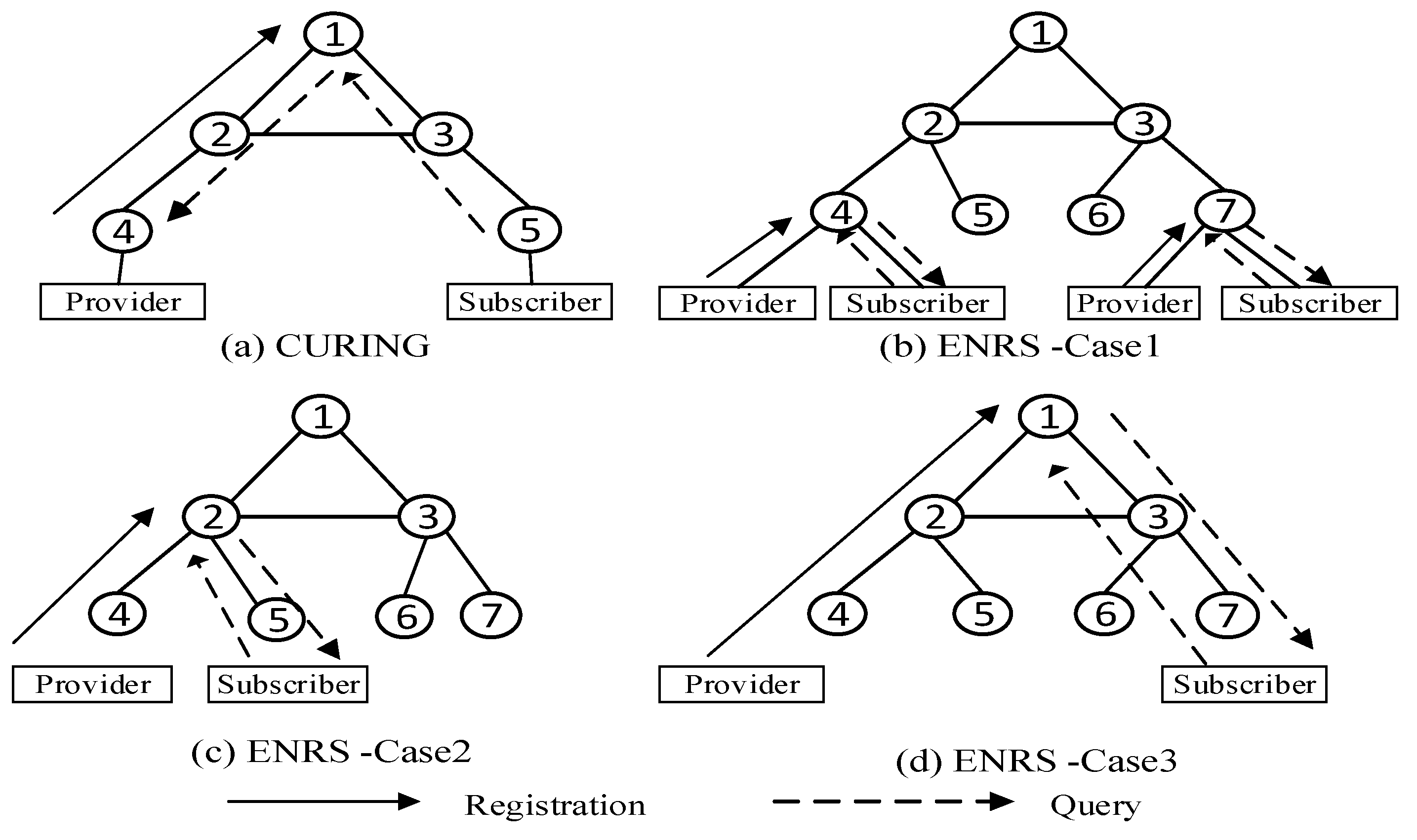
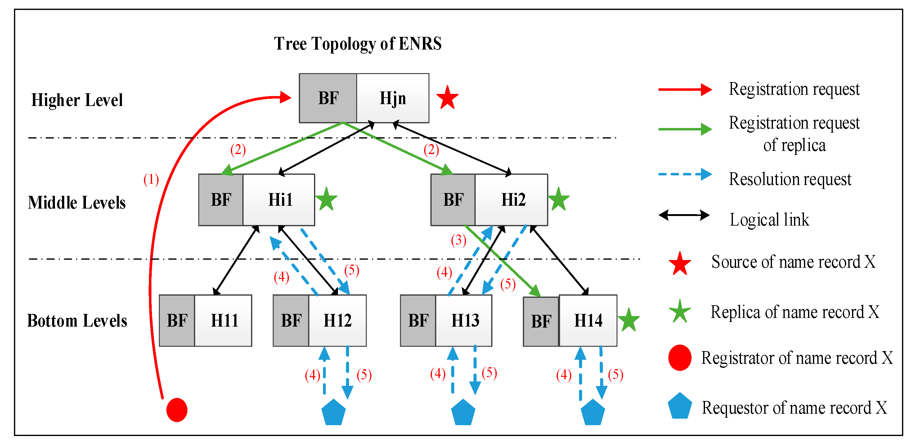
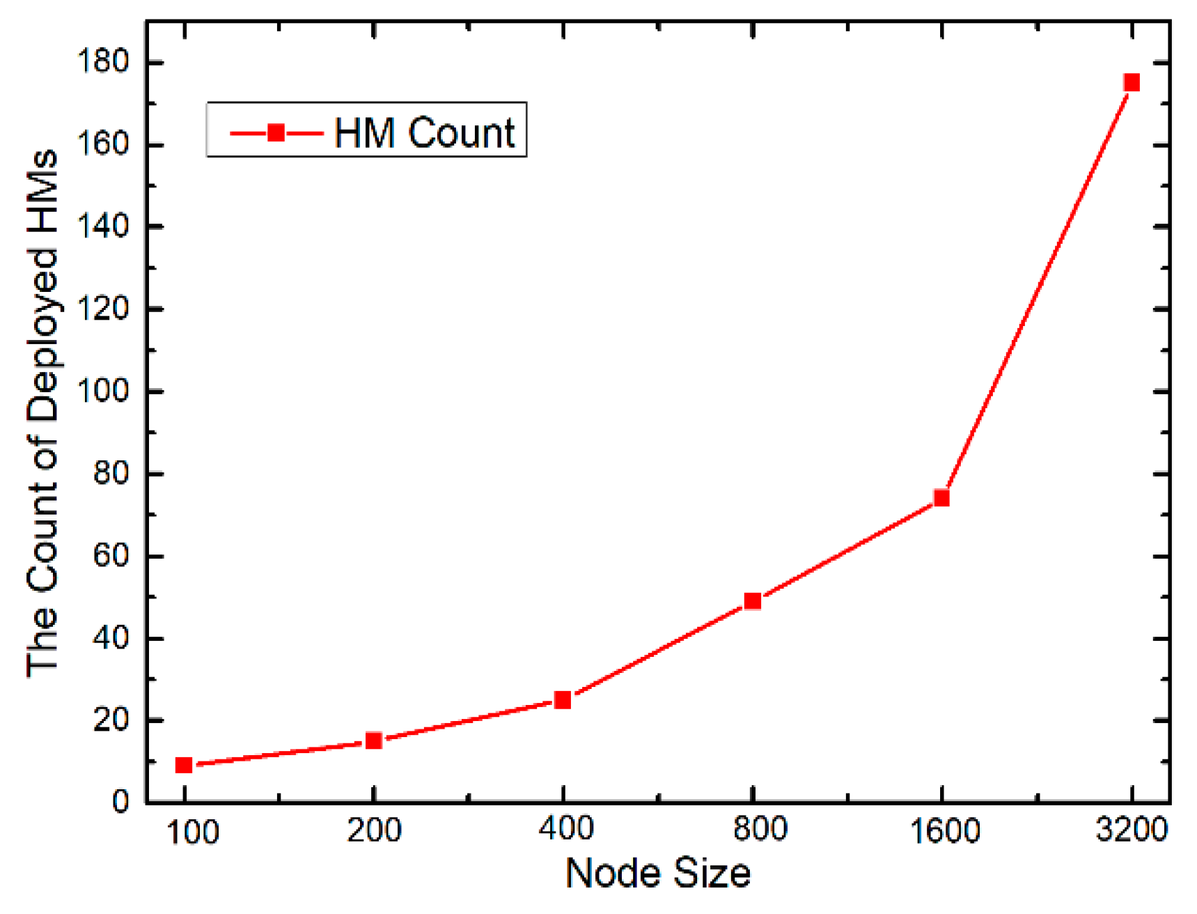
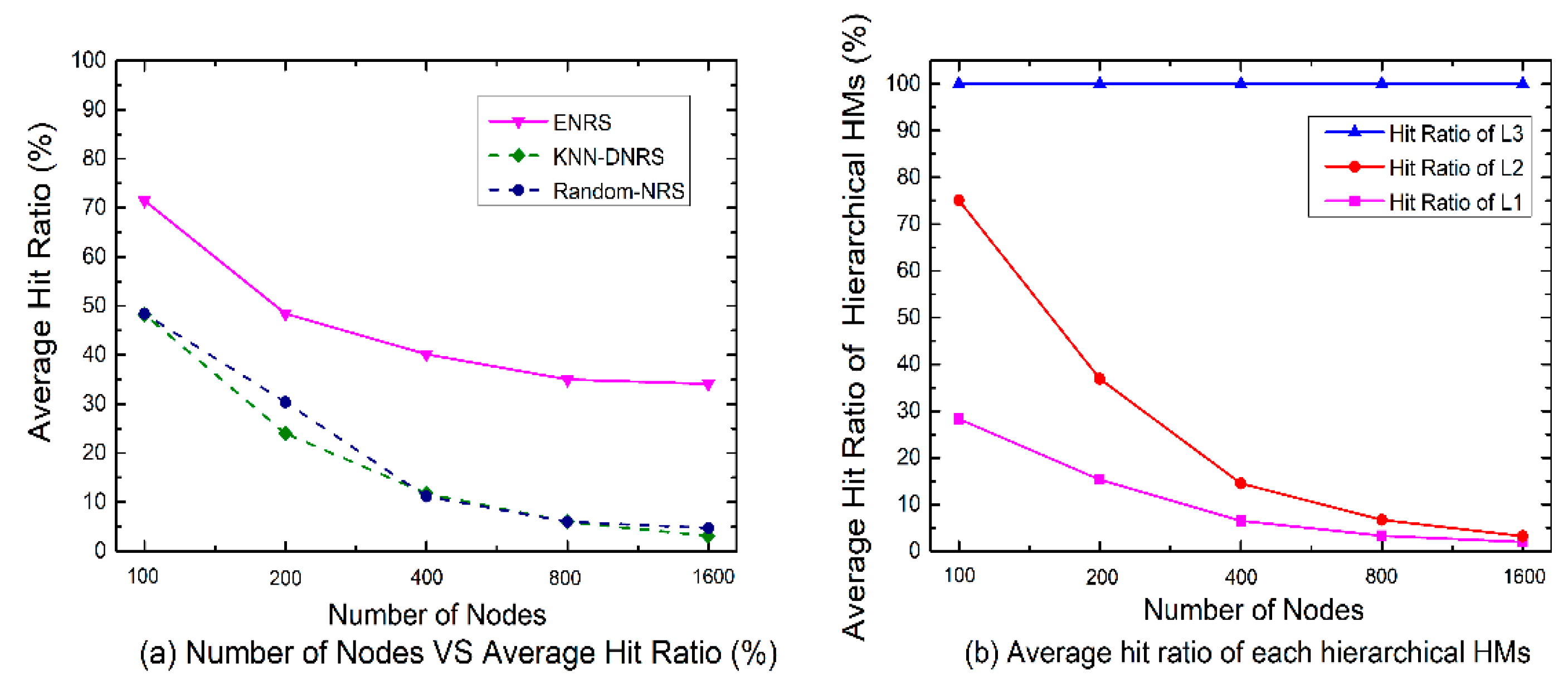
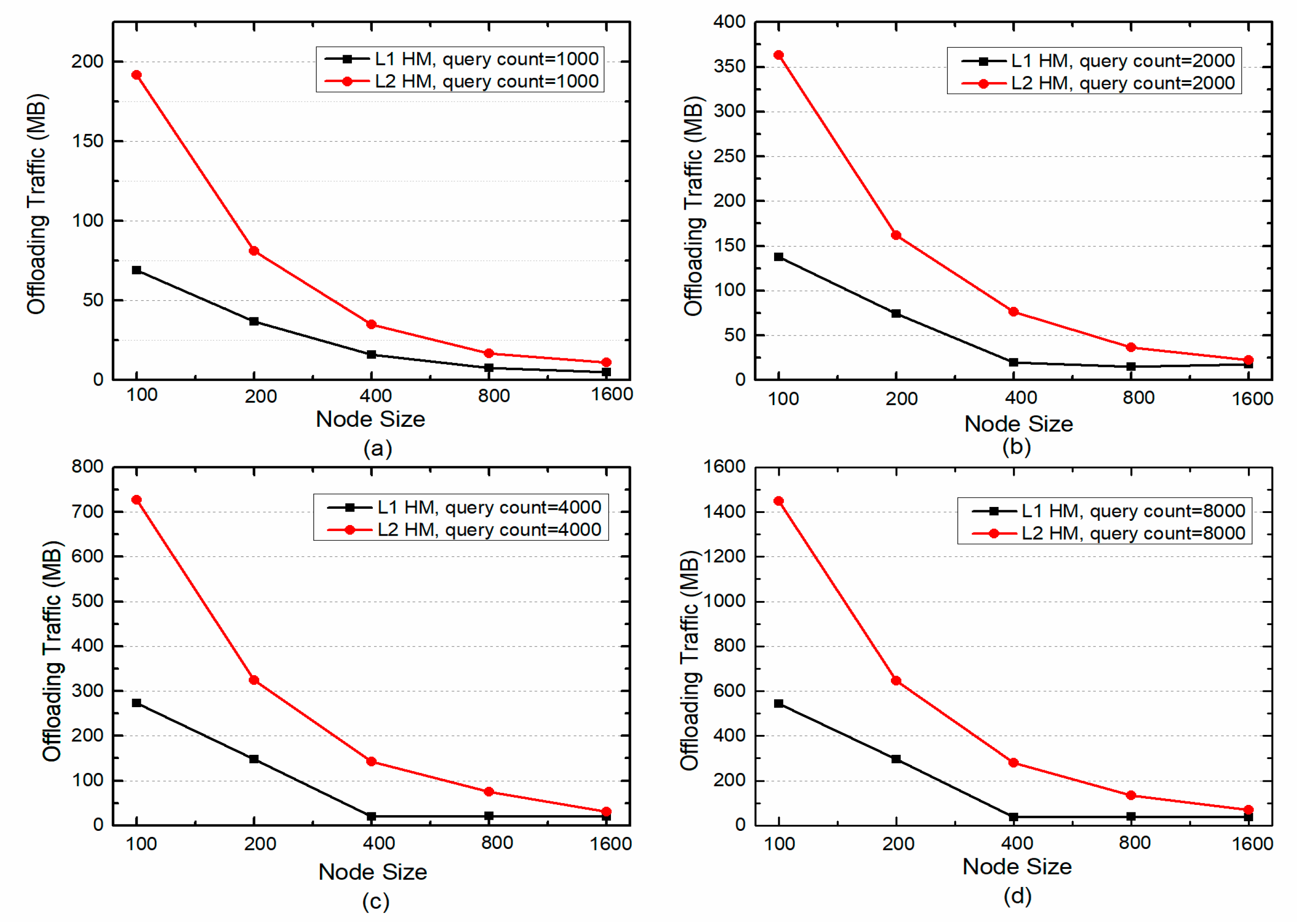
Table 1.
The meaning of symbols in Algorithm 1.
| Symbol | Meaning | Symbol | Meaning |
|---|---|---|---|
| the hierarchical number of Hierarchical Elastic Areas (HEA) | the count of selected resolver location | ||
| the count of partitional i-th level HEA | the node set of | ||
| the partitioning latency bound of i-th level HEA | the node count of | ||
| the k-th resolver of i-th level HEA | the node count of | ||
| the candidated resolver location of j-th HEA in i-th level. | the count of i-th level HEA | ||
| the resolver location set of all the i-th level HEA | the set of nodes belonging to the k-th HEA in i-th level | ||
| the node set of i-th level input graph the m-th subgraph of G in i-th level | - | the node set of i-th level input graph - |
Table 2.
The meaning of symbols in Algorithm 2.
| Symbol | Meaning | Symbol | Meaning |
|---|---|---|---|
| the peer resolver set to forward message | the time cost for single hop | ||
| the time receiving the request | current resolver | ||
| the total delay from requestor to current node | the peer neighboring resolver of | ||
| the delay between and | the node set in the DNHT of |
Table 3.
Evaluation setting.
| Parameter | Value | Parameter | Value |
|---|---|---|---|
| L | 3 | BF length | 1MB |
| Latency scope (ms) | (0,10] | m degree | 2 |
| Entity ID (EID) published | 10,000 | ||
| Number of nodes | 100,200,400,800,1600 | ||
| EID queried | 1000,2000,4000,8000 | ||
| Publisher proportion | 1.0 | ||
| Subscriber proportion | 1/4, 1/2, 3/4 | ||
Table 4.
The length of messages.
| System Name | REGISTER Message | QUERY Message |
|---|---|---|
| ENRS | 240 bits | 248 bits |
| KNN-DNRS | 224 bits | 224 bits |
| Random-NRS | 224 bits | 224 bits |
© 2019 by the authors. Licensee MDPI, Basel, Switzerland. This article is an open access article distributed under the terms and conditions of the Creative Commons Attribution (CC BY) license (http://creativecommons.org/licenses/by/4.0/).
Share and Cite
MDPI and ACS Style
Liao, Y.; Sheng, Y.; Wang, J. A Temporally Hierarchical Deployment Architecture for an Enhanced Name Resolution System. Appl. Sci. 2019, 9, 2891. https://doi.org/10.3390/app9142891
AMA Style
Liao Y, Sheng Y, Wang J. A Temporally Hierarchical Deployment Architecture for an Enhanced Name Resolution System. Applied Sciences. 2019; 9(14):2891. https://doi.org/10.3390/app9142891
Chicago/Turabian StyleLiao, Yi, Yiqiang Sheng, and Jinlin Wang. 2019. "A Temporally Hierarchical Deployment Architecture for an Enhanced Name Resolution System" Applied Sciences 9, no. 14: 2891. https://doi.org/10.3390/app9142891
Note that from the first issue of 2016, this journal uses article numbers instead of page numbers. See further details here.