Refined Study on Free Vibration of a Cable with an Inertial Mass Damper


1
International Joint Research Lab for Eco-building Materials and Engineering of Henan Province, North China University of Water Resources and Electric Power, Zhengzhou 450045, China
2
Key Laboratory of Concrete and Prestressed Concrete Structure of Ministry of Education, Southeast University, Nanjing 210096, China
*
Author to whom correspondence should be addressed.
Appl. Sci. 2019, 9(11), 2271; https://doi.org/10.3390/app9112271
Submission received: 13 April 2019
/
Revised: 22 May 2019
/
Accepted: 27 May 2019
/
Published: 1 June 2019
(This article belongs to the Special Issue Energy Dissipation and Vibration Control: Materials, Modeling, Algorithm and Devices)
Abstract
:To accurately predict the optimum supplemental modal damping ratio of the cable and the corresponding size of the inertial mass damper (IMD), combined effects of the cable sag, the cable flexural rigidity, and the boundary conditions on the control performance of the cable with the IMD are well investigated in this refined study. An analytical model of the cable-IMD system considering these effects is developed. The equation of motion of the cable-IMD system is transformed into a complex eigenvalue problem through the finite difference method. Experimental results from a scaled cable model with an IMD are then used to verify theoretical solutions. Three typical cables in actual cable-stayed bridges are selected for case studies. The results show that the theoretically predicted modal damping ratios of the cable with an IMD, taking into account the sag and the flexural rigidity, agree well with those identified from experimental results, while would be often overestimated with a taut-cable model. Moreover, experimental damping ratios of the cable always fall between those theoretically calculated with fixed ends or pinned ends for each case. Finally, to be conservative in actual design, it is recommended to use the cable-IMD system model with fixed ends to calculate the required damper size and predict the resulting modal damping ratio of the cable, since the corresponding theoretical solution often gives the lower bound of supplemental damping ratio of the cable.
1. Introduction
Long steel stay cables, commonly used in cable-stayed bridges, are highly susceptible to dynamic excitations due to their high flexibility and low inherent damping [1,2,3,4,5]. Large oscillations may reduce life span of cables and have detrimental effects on public confidence in the safety of the bridge [6,7]. Structural vibration control methods, including passive control [8], semi-active control [9,10], and active control [11], have been well developed and used for protecting structures against dynamic loading. For stay cables, modifying aerodynamic cable surface [12], connecting multiple cables together [13], installing external dampers [14,15], and combining external dampers with cross-ties [16,17], have been proposed to eliminate such vibrations. Among them, transversely attaching a passive viscous damper to the stay cable has been widely implemented in practical applications [18,19]. However, the supplemental damping induced by passive viscous dampers would be insufficient to eliminate vibrations effects of super long stay-cables since the damper location is typically restricted to the vicinity of the bridge deck for aesthetic and practical reasons [20,21].
As a more efficient solution, active or semi-active control, especially MR-based smart damping technology has attracted extensive attention from the community [22,23]. The MR damper can produce a damper force-deformation relationship with the negative stiffness behavior that benefits damper efficiency when the linear quadratic regulator (LQR) algorithm is employed [24,25,26,27]. Recently, an innovative mobile tuned mass damper (TMD) system, consisting of a mobile TMD device and a semi-active MR damper, has shown a better control performance than its passive counterparts when the fuzzy control algorithms were employed [28]. However, active or semi-active control requires an external stable power supply, a sensing system, a controller, etc. [29,30,31,32], which is complicated and costly. To solve this problem, great efforts have been devoted to seeking innovative passive dampers with similar negative stiffness mechanism.
Passive negative stiffness dampers (NSDs), the superposition of negative stiffness devices with passive viscous dampers, have been theoretically and experimentally proved to be able to provide superior achievable modal damping to the cable over that of traditional passive viscous dampers [33,34,35,36,37,38]. Recent study has also shown that the combined effects of a concentrated mass and a viscous damper can also behave like that of the passive NSD [39]. However, its control performance seems to be sensitive to the extra mass attachment on the cable. As an alternative, many inerter-based devices have been developed, and their control performance advantages have been well demonstrated for civil engineering structures [40,41,42,43,44,45,46,47,48]. In particular, the behaviors of typical inertial mass dampers (IMDs) [49,50,51] or tuned inerter dampers (TIDs) [52,53] to suppress cable vibrations have been theoretically investigated and identified through an ideal taut-cable model. The results indicated that similar to the NSD, the IMD can also show negative stiffness that benefits damper efficiency. Moreover, there is no instability issue for the IMD, while it would be observed when passive negative stiffness of the NSD is extremely larger. A TID system, where the traditional tuned mass damper (TMD) mass is replaced by an inerter, can offer the potential for much higher mass ratios than that of the TMD.
To facilitate efficient damper design and accurately predict the dynamic behavior of a cable with a passive or semi-active damper, the influences of the cable sag and the cable flexural rigidity on the damper efficiency have been investigated. It was found that nearly symmetric vibrations of the cable, especially in the first mode, were significantly affected by the cable sag, while the antisymmetric vibrations were hardly affected by the cable sag [54,55,56]. As for cable flexural rigidity, it has negative effects on the control performance for each mode of the cable [57,58]. The presence of cable flexural rigidity results in the smaller maximum achievable damping ratio and the higher optimal damping coefficient than those predicted by the taut-cable model for the case of fixed-fixed boundary condition [59,60]. The significance of boundary conditions on the dynamic behavior of cable-damper system was also addressed [61,62]. Results have shown that the adverse effect of flexural rigidity becomes more significant when the boundary conditions of the stay cable change from pinned-pinned to fixed-fixed ends. A recent study by the authors has further examined the control performance of the IMD on a sagged cable [63]. However, the effects of the flexural rigidity and the boundary condition of a cable on the vibration mitigation performance of an IMD have not been evaluated. Therefore, this refined study extends the aforementioned work by the authors to further investigate the combined effects of the cable sag, the cable flexural rigidity and the boundary condition on the control performance of the cable with the IMD.
In the current study, an analytical model of the cable-IMD system considering cable sag and cable flexural rigidity for different boundary conditions is developed. The equation of motion of the cable-IMD system is then transformed into a complex eigenvalue problem using the finite difference method. Subsequently, the data from a series of vibration control experiments on a scaled cable model with an IMD previously conducted by the authors are used to further verify the validity of theoretical results above. Finally, case studies on three typical cables in actual cable-stayed bridges are carried out to further explore combined effects of the cable sag, the cable flexural rigidity, together with boundary conditions on the control performance of the IMD.
2. Formulation of the Cable-IMD System
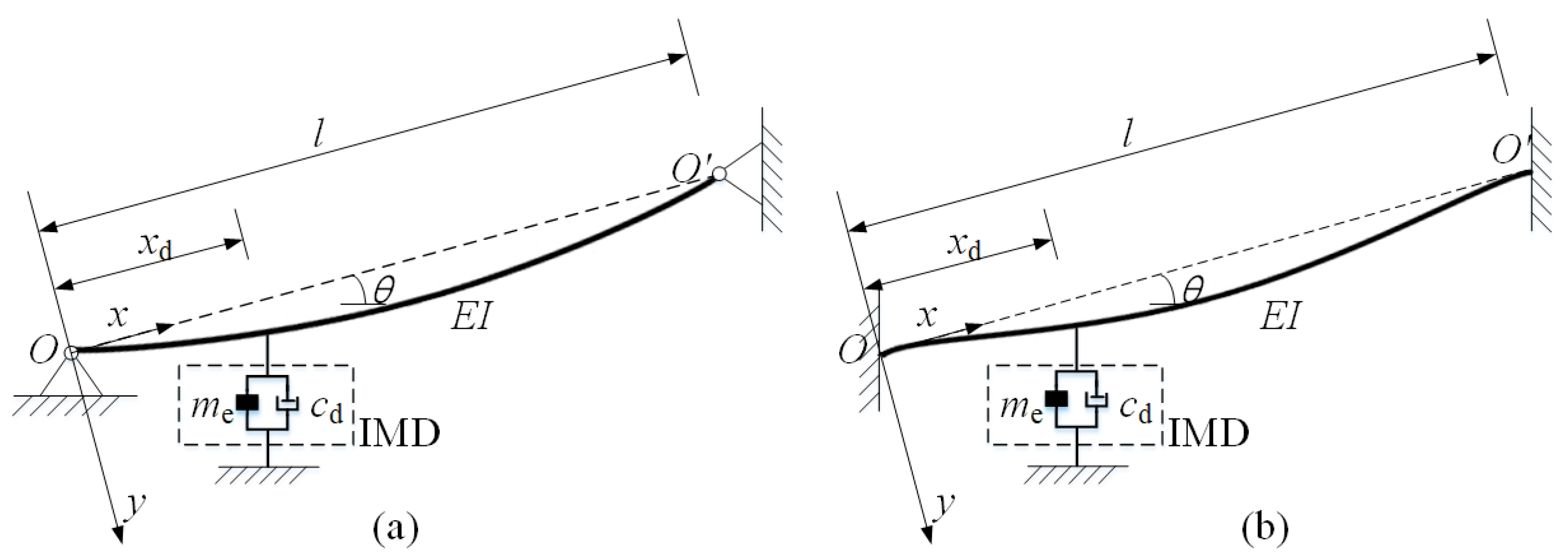
Consider an inclined cable with sag and flexural rigidity as shown in Figure 1. The coordinate system is defined such that the x-axis and the y-axis are along the cable chord OO’ and the transverse direction, respectively. An IMD is attached at the location of xd away from the cable lower end.
After introducing the assumptions that: (1) the sag-to-span ratio is sufficiently small; (2) the cable vibrates only in the x y-plane and its motion in the x-direction is negligible; (3) the cable has a uniform cross-section along its length; (4) the static profile of the cable is a second-order parabola [64]. The equation of motion of the cable-IMD system shown in Figure 1 can be expressed as
where EI is the flexural rigidity of the cable, y(x, t) is the in-plane transverse cable motion due to vibration at location x and time t, T is the tension force along the chord OO’, l is the length of the cable, c is the viscous damping per unit length, m is the cable mass per unit length, δ(∙) is the Dirac delta function. FIMD is the damper force of the IMD with the expression as
where and denote the inertial mass and the damping coefficient of the IMD, respectively. is the non-dimensional parameter for sag extensibility
where g is the gravity acceleration, EA is the extensional rigidity of cable, θ is the inclination angle, and Le is the static (stretched) length of the cable
The Equation (1) can be discretized using the finite difference method given by Tabatabai and Mehrabi [59] and further considering the corresponding boundary conditions (i.e., for pinned ends or for fixed ends. The ( )′ and ( )″ denote the first and second derivatives with respect to x, respectively.). For a discretized cable with N equal elements and n = N−1 internal nodes between two cable ends, the transverse displacement of the cable can be expressed as
where is the complex eigenvalue pair and is the corresponding eigenvector. is modal frequency, is modal damping ratio and is displacement of the ith internal node.
Therefore, the discretized equation in the matrix form can be derived as
where , , are the stiffness matrix, the damping matrix and the mass matrix, respectively. According to the reference [59], the stiffness matrix is defined as
where
where a = l/N is discretized element length of the cable; is full unit matrix. Since the IMD properties are linear, the IMD can be treated as an inherent element of the cable-damper system, and the effects of the IMD can be easily integrated in the mass matrix and damping matrix of the cable. If an IMD is attached at the jth internal node, the mass and damping matrix of the cable can be expressed as
where I is a n × n identity matrix, is the IMD load vector and .
Equation (6) can be transformed into an equivalent complex eigenvalue problem shown in the following form
where , , .
Therefore, the modal frequency and the modal damping ratio of the cable can be found by Equation (11). Actually, the inherent cable damping for the real cable is sufficiently small, which is always neglected for cable vibration control design with dampers [15,20,35,51,57,58]. Thus, the inherent cable damping was assumed to be zero in the following theoretical eigenvalue analysis.
3. Verification of Theoretical Results
To further verify the accuracy of the finite difference method for the cable-IMD system, the experimental data from the free vibration tests of the model cable with an electromagnetic inertial mass damper (EIMD) were used. The detailed description of the experiment can be referenced to Wang et al. [65]. The main properties of the model cable are shown in Table 1. An EIMD, which mainly consists of a rotary generator, a ball screw, a liner guide way and a flywheel, was attached transversely to the model cable at 0.114 m (i.e., 1% of the cable length) away from the anchorage. In the experiment, the equivalent damping coefficient and the inertial mass of the EIMD were adjusted by changing the load resistance of the generator and the size of the flywheel, respectively. The equivalent damping coefficient and inertial mass of the EIMD were identified by the least square method according to the measured displacement and the force of the EIMD. Modal damping ratios of the model cable were identified through fitting the envelope curve of the free decay cable responses with an exponential function. In the theoretical calculation, the cable is divided into 200 equally spaced segments with 199 internal nodes (N = 199), and the EIMD locates at the second internal node.
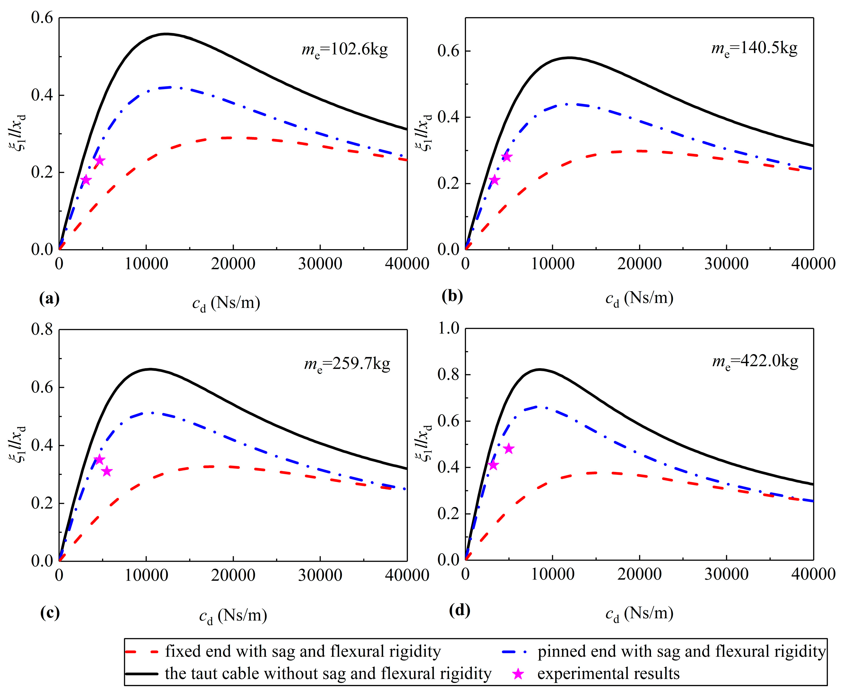
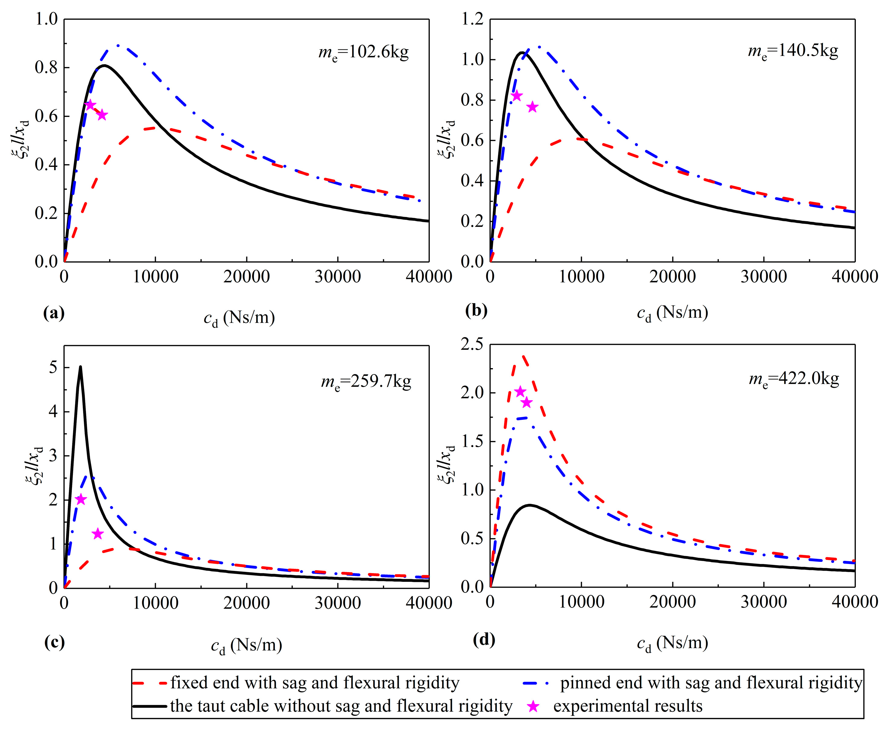
The theoretical and experimental supplemental modal damping ratios in the first two modes of the cable are compared in Figure 2 and Figure 3. For the convenience of comparison, theoretical results for the taut cable model are also shown. It is noteworthy that a taut-cable model generally overestimates the supplemental modal damping ratios of the cable in most cases. Nevertheless, the supplemental modal damping ratios theoretically predicted by the refined model of the cable-IMD system agree well with those identified from experimental results. Furthermore, experimental damping ratios always fall between theoretical results with fixed ends or pinned ends for each case, which implies the cable anchorages in the experiment were not ideally fixed or pinned. It is also observed that the difference of the optimum supplemental modal damping ratios and the corresponding damping coefficients between the cable with fixed and the cable with pinned increases with the increase of the inertial mass of the IMD. This demonstrated that the effect of boundary conditions would be amplified with the increase of inertial mass of the IMD. Hence, the results clearly indicate that considering the effects of the cable sag, the cable flexural rigidity, and the boundary condition is essential to give a more accurate prediction in evaluating the vibration control performance of a stay cable with an IMD and designing an optimum IMD for cable vibration mitigation.
Table 2 and Table 3 summarize the first two supplemental modal damping ratios obtained in the theoretical calculation and experimental tests. As expected, the discrepancies between experimental and theoretical results based on the taut-cable model are significant. Moreover, the errors between the theoretical results of the refined model and experimental results are particularly considerable when the inertial mass approaches the optimum value. For instance, the discrepancies are over 80% in some cases. A possible explanation for the discrepancies is that there are inevitable experimental identification errors in important parameters, such as the supplemental modal damping ratio, the inertial mass and the equivalent damping coefficient of the IMD. Another possible explanation is that the differences between theoretical model and test model cause the discrepancies between the theoretical and test results. Identifications of the cable flexural rigidity and the cable sag and the uncertainty of boundary conditions are also possible error sources. And the effect of boundary conditions would be amplified with the increase of inertial mass of the IMD. The uncertainty of boundary conditions can cause large errors between experimental and theoretical results when the inertial mass approaches the optimum value. Similar observations can also be found in cable vibration control with a negative stiffness damper [35].
4. Case Studies
Previous studies often introduce a dimensionless parameter for flexural rigidity to investigate the individual effects of flexural rigidity or the combined effects of sag and flexural rigidity on the dynamic properties of a stay cable with a damper [57,58,59,60,61]. However, the dynamic properties of the stay cable may have obvious differences even that the dimensionless bending-stiffness for various cables are the same. Alternatively, three typical cables (a short cable, a medium cable and a long cable) in actual cable-stayed bridges are selected as example cables to explore the influence of the sag and the flexural rigidity with different boundary conditions on the control performance of the cable with the IMD in this section. It should be pointed out that the lengths of short, medium and long cables are relative values and their definitions are mainly referred to the Xu and Yu [54]. The properties of three typical cables in cable-stayed bridges are shown in Table 4. An IMD is assumed to be attached to each cable at a distance of the 1% length from its lower end without considering practical application especially for the long cable. The modal damping ratios in the first four modes of each cable are obtained using the finite difference method above. The damping coefficient cd and the inertial mass of the IMD can be normalized as,
where and are the dimensionless damping coefficient and the dimensionless inertial mass of the IMD, respectively; is the nth modal frequency of an undamped taut cable.
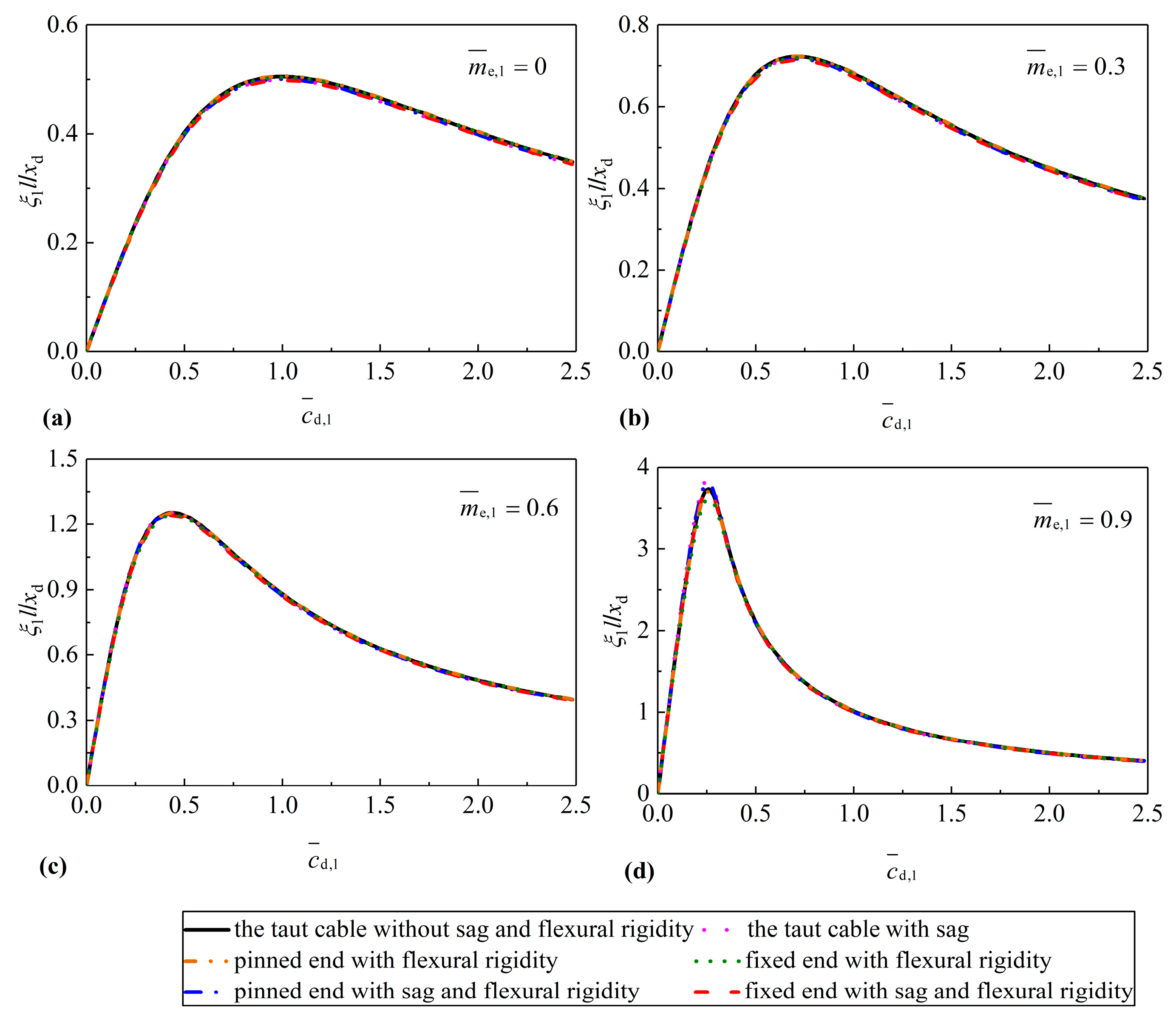
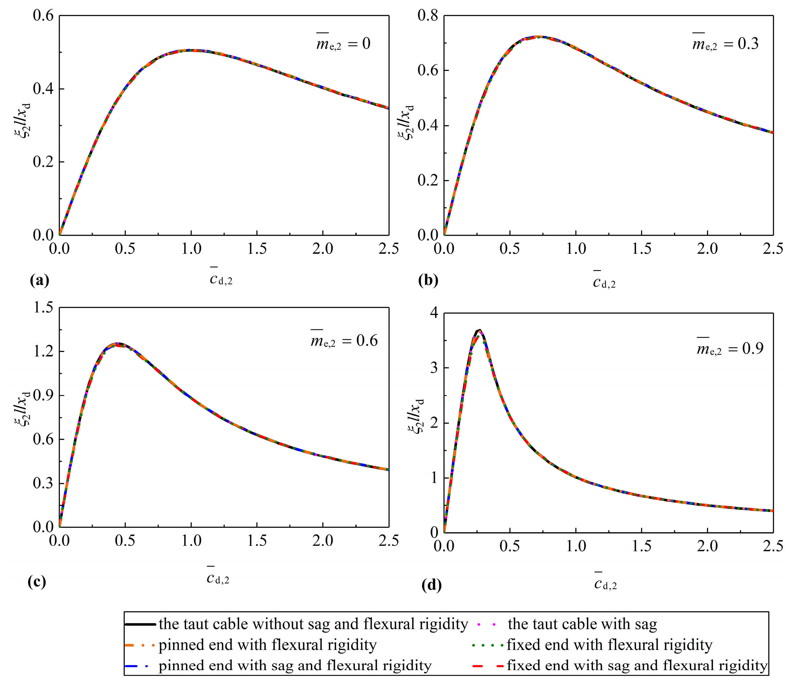
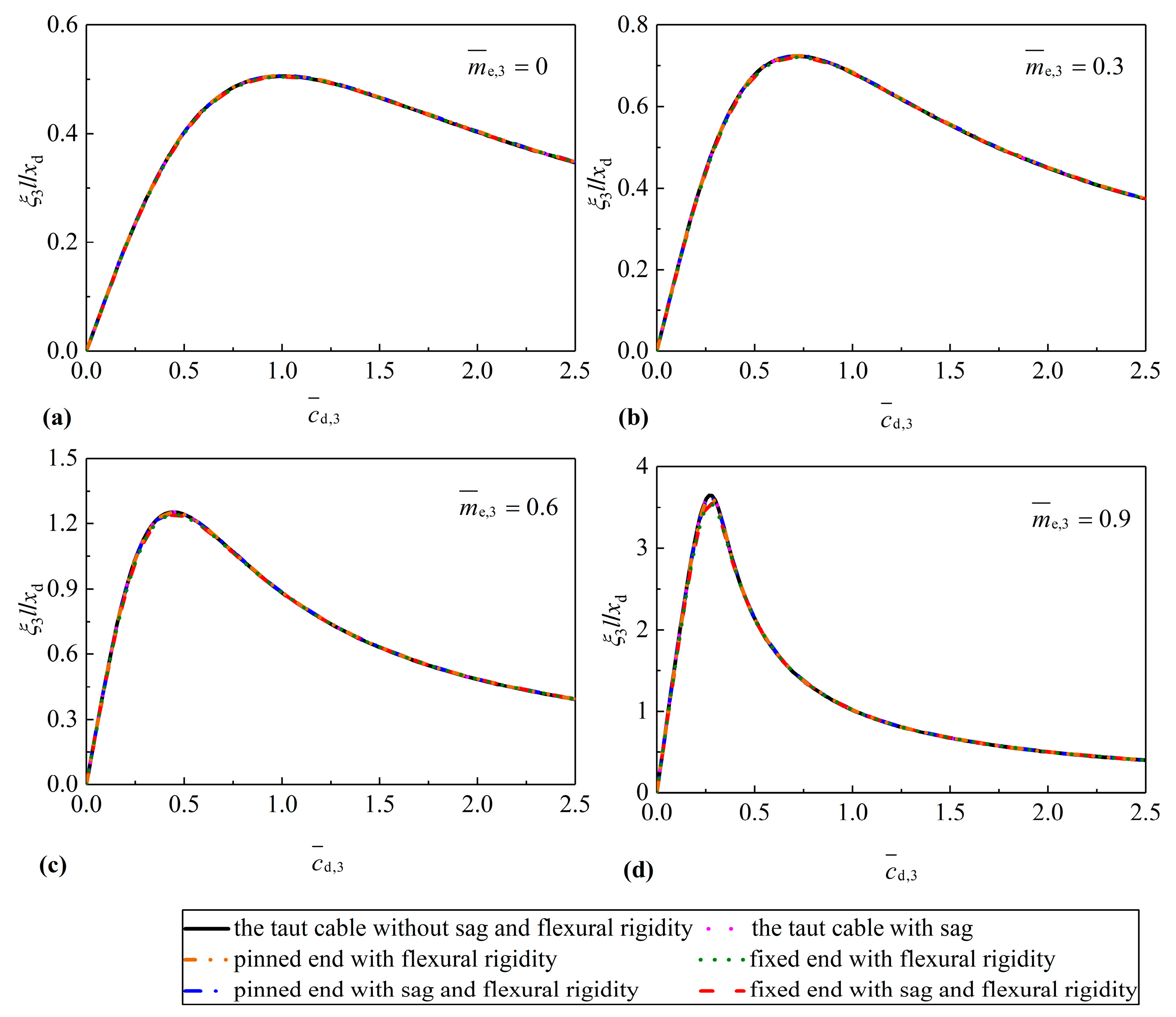
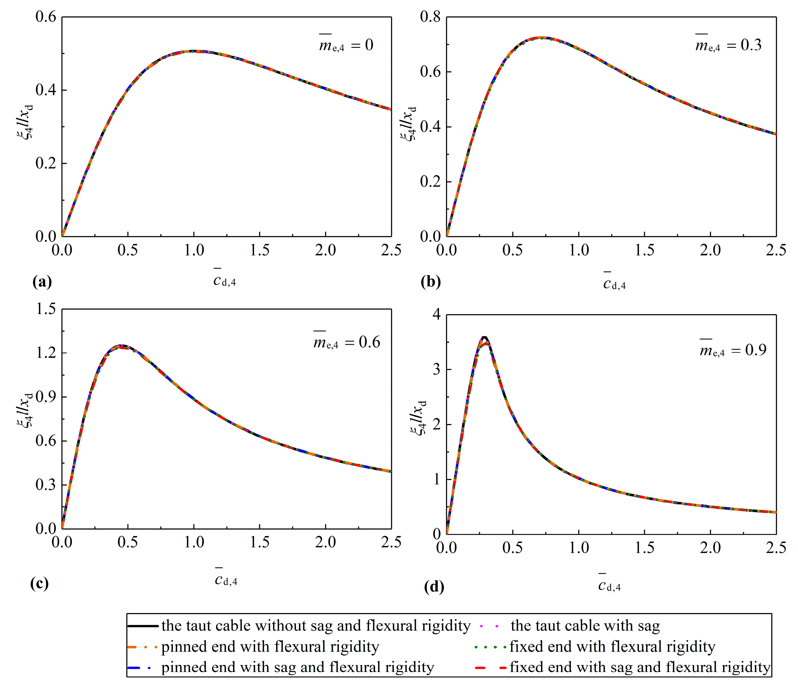
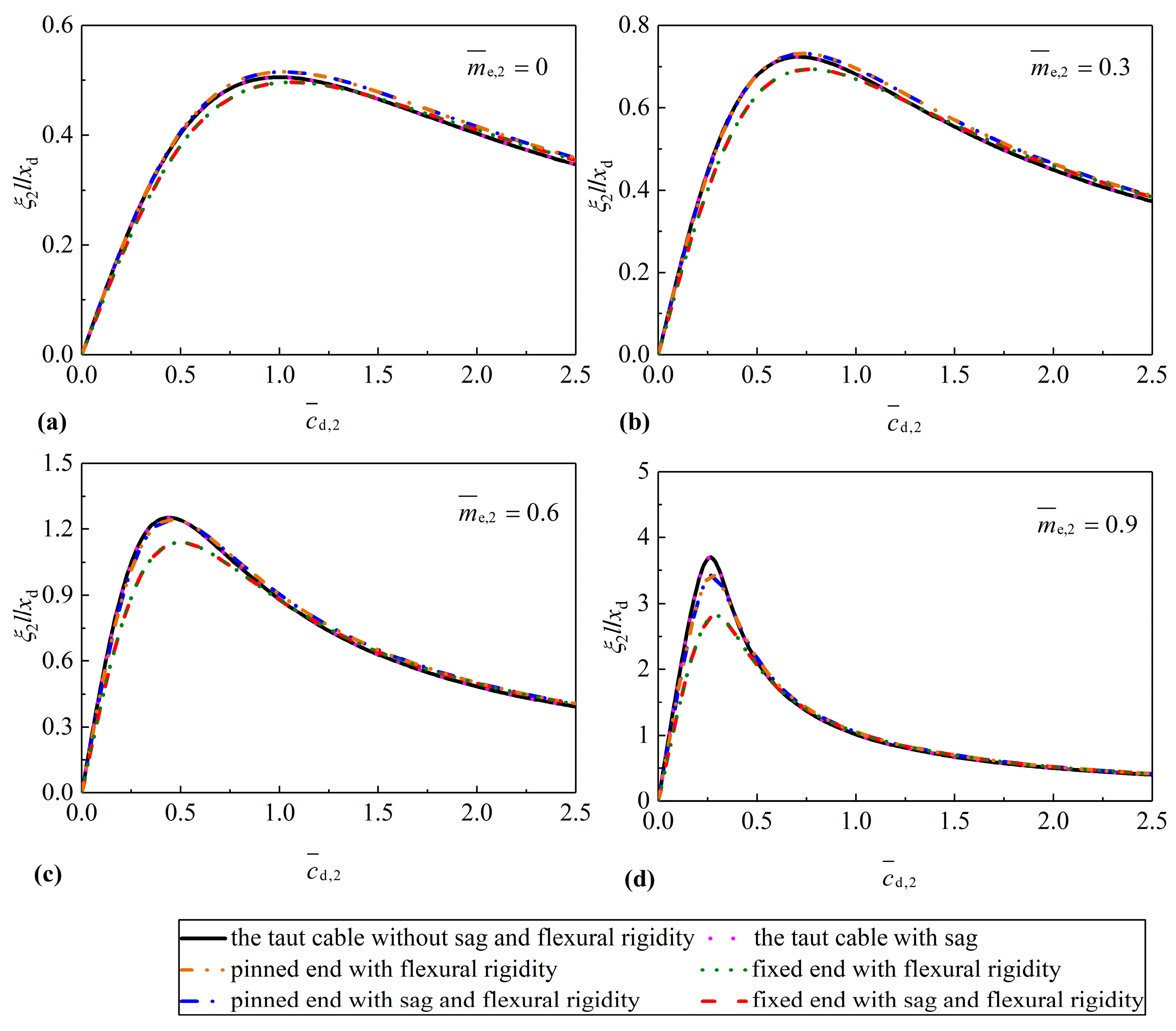
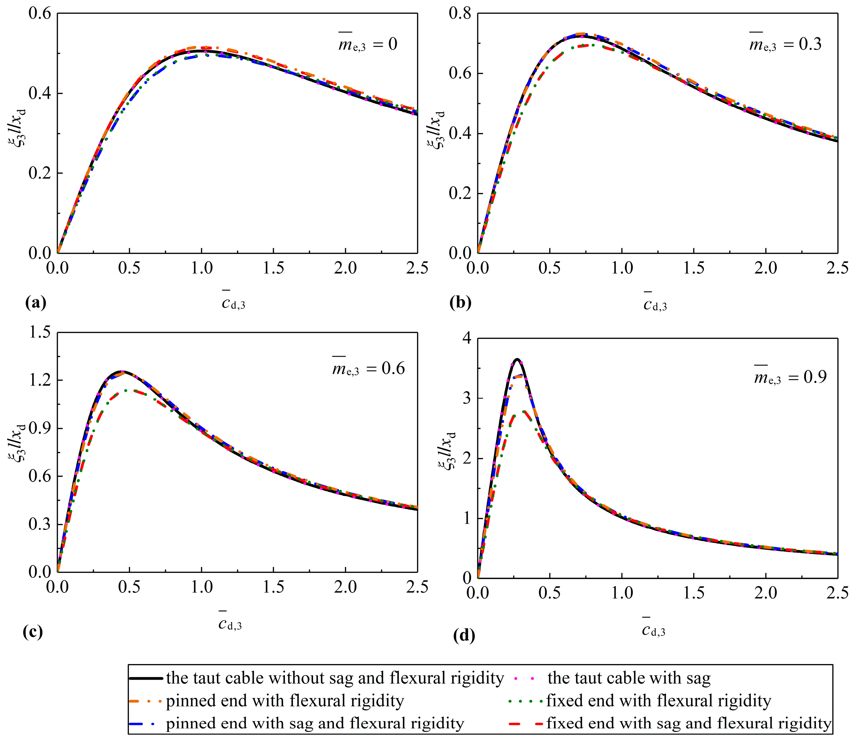
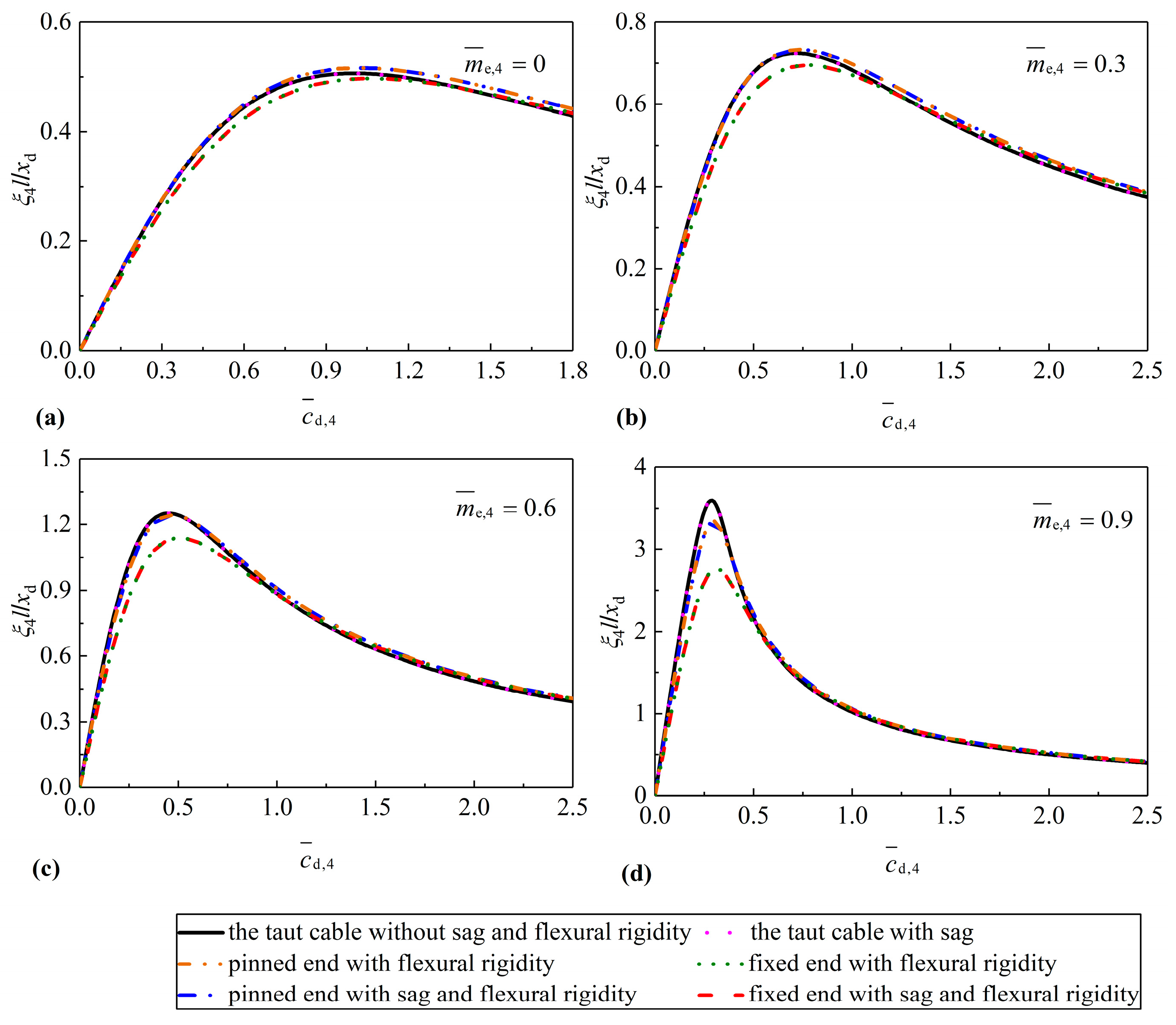
Figure 4, Figure 5, Figure 6 and Figure 7 present the supplemental modal damping ratios in the first four modes of the short cable versus damping coefficients for various inertial masses of the IMD. The single impact of cable sag or cable flexural rigidity and their combined effects on the performance of the cable with the IMD are given. For the convenience of comparisons, theoretical results with the taut cable model are also shown. All curves for the first four modal damping ratios of the short cable almost coincide with each other when the dimensionless inertial mass is the same, indicating that presences of the cable sag, the cable flexural rigidity and the boundary condition have negligible effects on the control performance of the IMD in mitigating short cable vibration. It is mainly because the short cable with low cable sag and low flexural rigidity used here is close to the taut cable model assumption. Hence, the taut cable model is still suitable for the short cable to rapidly design an optimum IMD and evaluate corresponding control performance.
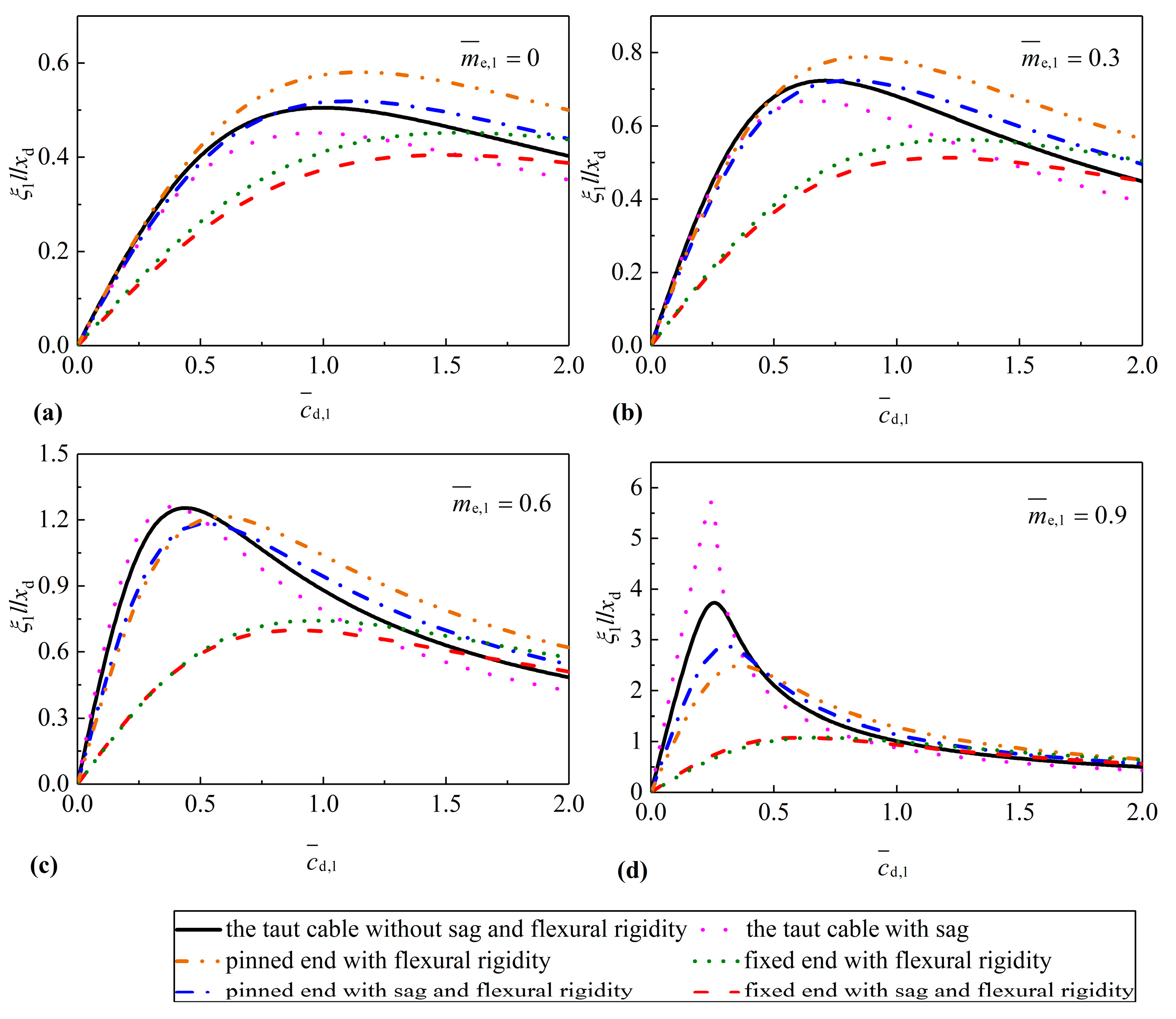
Figure 8, Figure 9, Figure 10 and Figure 11 present the supplemental modal damping ratios in the first four modes of the medium cable versus damping coefficient for various inertial masses of the IMD. The maximum achievable damping ratios in the first mode are highly sensitive to the cable sag while those in the higher modes are hardly affected. Generally, the cable sag reduces the optimal modal damping ratios. However, the optimal first modal damping ratios of the cable begin to increase when the inertial mass shown in Figure 8d is adopted. Compared to the cable sag, the flexural rigidity has almost the same effect on all concerned cable modes. For the case of fixed-fixed boundary condition of the cable, the flexural rigidity tends to reduce the maximum modal damping ratios. Moreover, the adverse effect of the cable flexural rigidity on damper efficiency will be amplified with the increase of the inertial mass of the IMD. While for the case of pinned-pinned boundary condition of the cable, unlike the results of the fixed-fixed cable, the flexural rigidity can increase the maximum achievable damping ratios of the cable for the IMD with small inertial mass (). However, the maximum achievable damping ratios begin to decrease when medium inertial mass () is adopted. It is also found that the flexural rigidity will result in larger optimal damping coefficients whether the boundary conditions of the medium cable are fixed or pinned. In general, considering combined effects of the cable sag and the flexural rigidity, the maximum achievable damping ratio of the fixed-fixed cable with the IMD will be the lower bound, while the corresponding optimal damping coefficient will be the upper bound.
Figure 12, Figure 13, Figure 14 and Figure 15 present the supplemental modal damping ratios in the first four modes of the long cable versus damping coefficient for various inertial masses of the IMD. Similarly to the medium cable, both the cable sag and the cable flexural rigidity mainly have adverse influences on the IMD effectiveness for cable vibration control. Moreover, the maximum achievable damping ratio of the cable-IMD system considering the influence of the cable sag and the cable flexural rigidity in the case of fixed boundary conditions provides relatively conservative predictions. Unlike the medium cable, the cable sag plays a dominant role in the dynamic behavior of an IMD to suppress cable vibrations for the lower modes of interest, especially for the first mode, while the presence of the cable flexural rigidity has fewer effects on the performance efficiency of the long cable with the IMD.
5. Conclusions
In this paper, a refined free vibration analysis has been conducted to evaluate the IMD efficiency in suppressing cable vibration. An analytical model of cable-IMD system has been developed based on finite difference method. The accuracy of the finite difference method has been verified via experimental results from a scaled cable modal with an IMD. The effects of the cable sag, the cable flexural rigidity and the boundary conditions on the cable control performance have been evaluated via three typical cables in actual cable-stayed bridges.
The theoretically predicted modal damping ratios based on the refined model of cable-IMD system agree well with those identified from experimental results, while they would be often overestimated based on a taut-cable model. Moreover, the experimental modal damping ratios generally fall between those theoretically predicted with fixed ends or pinned ends of the cable.
The cable sag has significant effects on the first mode whereas it has almost no effects on the higher modes of the cable. Moreover, the influence of the cable sag becomes more remarkable with the increase of cable length. Nevertheless, the cable flexural rigidity has effects on each mode of interest, and it has the most significant impact on the medium cable, followed by the long cable. The effects of cable sag and cable flexural rigidity on the control performance of the short cable with low cable sag and low flexural rigidity can be neglected.
Considering the combined effects of the cable sag and the cable flexural rigidity, the maximum achievable modal damping ratio of a fixed-fixed cable always provides a more conservative prediction than its pinned-pinned counterpart. Thus, it is recommended to consider the refined model of the cable-IMD system with fixed-fixed ends for predicting the optimum IMD size and corresponding attainable modal damping ratio. However, the taut-cable model is still suitable to rapidly design an IMD and predict the IMD efficiency for short cables with low cable sag and low flexural rigidity.
Author Contributions
Z.W., F.Y. and H.W. conceived the idea of this research; Z.W. and F.Y. wrote the paper; H.G. and B.F. reviewed and revised the paper.
Funding
The authors greatly acknowledge the financial support from the National Natural Science Foundation of China (Grant No. 51878274) and the National Basic Research Program of China (973 Program) (Grant No. 2015CB060000).
Conflicts of Interest
The authors declare no conflict of interest.
References
- Chen, Z.Q.; Wang, X.Y.; Ko, J.M.; Ni, Y.Q.; Spencer, B.F.; Yang, G. MR damping system for mitigating wind-rain induced vibration on Dongting Lake Cable-Stayed Bridge. Wind Struct. 2004, 7, 293–304. [Google Scholar] [CrossRef]
- Jakobsen, J.B.; Andersen, T.L.; Macdonald, J.H.G.; Nikitas, N.; Larose, G.L.; Savage, M.G.; McAuliffe, B.R. Wind-induced response and excitation characteristics of an inclined cable model in the critical Reynolds number range. J. Wind Eng. Ind. Aerod. 2012, 110, 100–112. [Google Scholar] [CrossRef]
- Nikitas, N.; Macdonald, J.H.G.; Jakobsen, J.B.; Andersen, T.L. Critical Reynolds number and galloping instabilities: Experiments on circular cylinders. Exp. Fluids 2012, 52, 1295–1306. [Google Scholar] [CrossRef]
- Mao, J.X.; Wang, H.; Feng, D.M.; Tao, T.Y.; Zheng, W.Z. Investigation of dynamic properties of long-span cable-stayed bridges based on one-year monitoring data under normal operating condition. Struct. Control Health Monit. 2018, e2146, 1–19. [Google Scholar] [CrossRef]
- Wang, H.; Mao, J.X.; Spencer, B.F. A monitoring-based approach for evaluating dynamic responses of riding vehicle on long-span bridge under strong winds. Eng. Struct. 2019, 189, 35–47. [Google Scholar] [CrossRef]
- Acampora, A.; Macdonald, J.H.G.; Georgakis, C.T.; Nikitas, N. Identification of aeroelastic forces and static drag coefficients of a twin cable bridge stay from full-scale ambient vibration measurements. J. Wind Eng. Ind. Aerod. 2014, 124, 90–98. [Google Scholar] [CrossRef]
- Nikitas, N.; Macdonald, J.H.G. Aerodynamic forcing characteristics of dry cable galloping at critical Reynolds numbers. Eur. J. Mech. B Fluid 2015, 49, 243–249. [Google Scholar] [CrossRef] [Green Version]
- Rezaei Rad, A.; Banazadeh, M. Probabilistic risk-based performance evaluation of seismically base-isolated steel structures subjected to far-field earthquakes. Buildings 2018, 8, 128. [Google Scholar] [CrossRef]
- Ni, Y.Q.; Chen, Y.; Ko, J.M.; Cao, D.Q. Neuro-control of cable vibration using semi-active magnetorheological dampers. Eng. Struct. 2002, 24, 295–307. [Google Scholar] [CrossRef]
- Duan, Y.F.; Ni, Y.Q.; Ko, J.M. State-derivative feedback control of cable vibration using semi-active MR dampers. Comput. Aided Civ. Inf. 2005, 20, 431–449. [Google Scholar] [CrossRef]
- Pakos, W.; Grosel, J. Reduction of cable vibrations in a cable stayed bridge under bi-harmonic excitation. Eng. Struct. 2019, 189, 1–10. [Google Scholar] [CrossRef]
- Kleissl, K.; Georgakis, C.T. Comparison of the aerodynamics of bridge cables with helical fillets and a pattern-indented surface. J. Wind Eng. Ind. Aerod. 2012, 104, 166–175. [Google Scholar] [CrossRef]
- Yamaguchi, H.; Nagahawatta, H.D. Damping effects of cable cross ties in cable-stayed bridge. J. Wind Eng. Ind. Aerod. 1995, 54, 35–43. [Google Scholar] [CrossRef]
- Pacheco, B.M.; Fujino, Y.; Sulekh, A. Estimation curve for modal damping in stay cables with viscous damper. J. Struct. Eng. 1993, 119, 1961–1979. [Google Scholar] [CrossRef]
- Wang, Z.H.; Chen, Z.Q.; Gao, H.; Wang, H. Development of a self-powered magnetorheological damper system for cable vibration control. Appl. Sci. 2018, 8, 1–17. [Google Scholar] [CrossRef]
- Zhou, H.J.; Yang, X.; Sun, L.M.; Xing, F. Free vibrations of a two-cable network with near-support dampers and a cross-link. Struct. Control Health Monit. 2015, 22, 1173–1192. [Google Scholar] [CrossRef]
- Ahmad, J.; Cheng, S.H.; Ghrib, F. Combined effect of external damper and cross-tie on the modal response of hybrid two-cable networks. J. Sound Vib. 2018, 417, 132–148. [Google Scholar] [CrossRef]
- Main, J.A.; Jones, N.P. Evaluation of viscous dampers for stay-cable vibration mitigation. J. Bridge Eng. 2001, 6, 385–397. [Google Scholar] [CrossRef]
- Zhou, H.J.; Sun, L.M.; Xing, F. Damping of full-scale stay cable with viscous damper: Experiment and analysis. Adv. Struct. Eng. 2014, 17, 265–274. [Google Scholar] [CrossRef]
- Krenk, S. Vibration of a taut cable with an external damper. J. Appl. Mech. 2000, 67, 772–776. [Google Scholar] [CrossRef]
- Fournier, J.A.; Cheng, S.H. Impact of damper stiffness and damper support stiffness on the efficiency of a linear viscous damper in controlling stay cable vibrations. J. Bridge Eng. 2013, 19, 04013022. [Google Scholar] [CrossRef]
- Christenson, R.E.; Spencer, B.F.; Johnson, E.A. Experimental verification of smart cable damping. J. Eng. Mech. 2006, 132, 268–278. [Google Scholar] [CrossRef]
- Duan, Y.F.; Ni, Y.Q.; Ko, J.M. Cable vibration control using magnetorheological dampers. J. Intell. Mater. Syst. Struct. 2006, 17, 321–325. [Google Scholar] [CrossRef]
- Li, H.; Liu, M.; Ou, J.P. Negative stiffness characteristics of active and semi-active control systems for stay cables. Struct. Control Health Monit. 2008, 15, 120–142. [Google Scholar] [CrossRef]
- Høgsberg, J. The role of negative stiffness in semi-active control of magneto-rheological dampers. Struct. Control Health Monit. 2011, 18, 289–304. [Google Scholar] [CrossRef]
- Weber, F.; Boston, C. Clipped viscous damping with negative stiffness for semi-active cable damping. Smart Mater. Struct. 2011, 20, 045007. [Google Scholar] [CrossRef]
- Weber, F.; Distl, H. Semi-active damping with negative stiffness for multi-mode cable vibration mitigation: Approximate collocated control solution. Smart Mater. Struct. 2015, 24, 115015. [Google Scholar] [CrossRef]
- Salari, S.; Hormozabad, S.J.; Ghorbani-Tanha, A.K.; Rahimian, M. Innovative Mobile TMD System for Semi-active Vibration Control of Inclined Sagged Cables. KSCE J. Civ. Eng. 2019, 23, 641–653. [Google Scholar] [CrossRef]
- Cai, C.S.; Wu, W.J.; Araujo, M. Cable vibration control with a TMD-MR damper system: Experimental exploration. J. Struct. Eng. 2007, 133, 629–637. [Google Scholar] [CrossRef]
- Liu, M.; Song, G.B.; Li, H. Non-model-based semi-active vibration suppression of stay cables using magneto-rheological fluid dampers. Smart Mater. Struct. 2007, 16, 1447–1452. [Google Scholar] [CrossRef]
- Li, H.; Liu, M.; Li, J.H.; Guan, X.C.; Ou, J.P. Vibration control of stay cables of Shandong Binzhou Yellow River Highway Bridge by using magnetorheological fluid dampers. J. Bridge Eng. 2007, 12, 401–409. [Google Scholar] [CrossRef]
- Weber, F.; Distl, H. Amplitude and frequencyindependent cable damping of Sutong Bridge and Russky Bridge by magnetorheological dampers. Struct. Control Health Monit. 2015, 22, 237–254. [Google Scholar] [CrossRef]
- Chen, L.; Sun, L.M.; Nagarajaiah, S. Cable with discrete negative stiffness device and viscous damper: Passive realization and general characteristics. Smart Struct. Syst. 2015, 15, 627–643. [Google Scholar] [CrossRef]
- Zhou, P.; Li, H. Modeling and control performance of a negative stiffness damper for suppressing stay cable vibrations. Struct. Control Health Monit. 2016, 23, 764–782. [Google Scholar] [CrossRef]
- Shi, X.; Zhu, S.Y.; Spencer, B.F. Experimental study on passive negative stiffness damper for cable vibration mitigation. J. Eng. Mech. 2017, 143, 04017070. [Google Scholar] [CrossRef]
- Javanbakht, M.; Cheng, S.H.; Ghrib, F. Refined damper design formula for a cable equipped with a positive or negative stiffness damper. Struct. Control Health Monit. 2018, e2236, 1–23. [Google Scholar] [CrossRef]
- Li, H.N.; Sun, T.; Lai, Z.L.; Nagarajaiah, S. Effectiveness of negative stiffness system in the benchmark structural-control problem for seismically excited highway bridges. J. Bridge Eng. 2018, 23, 04018001. [Google Scholar] [CrossRef]
- Zhou, P.; Liu, M.; Xiao, H.G.; Li, H. Feasibility of using a negative stiffness damper to two interconnected Stay Cables for damping enhancement. Int. J. Struct. Stab. Dyn. 2019, 1950058. [Google Scholar] [CrossRef]
- Zhou, H.J.; Huang, X.G.; Xiang, N.; He, J.W.; Sun, L.M.; Xing, F. Free vibration of a taut cable with a damper and a concentrated mass. Struct. Control Health Monit. 2018, e2251, 1–21. [Google Scholar] [CrossRef]
- Ikago, K.; Saito, K.; Inoue, N. Seismic control of single-degree-of-freedom structure using tuned viscous mass damper. Earthq. Eng. Struct. D 2012, 41, 453–474. [Google Scholar] [CrossRef]
- Lazar, I.F.; Neild, S.A.; Wagg, D.J. Using an inerter-based device for structural vibration suppression. Earthq. Eng. Strut. D 2014, 43, 1129–1147. [Google Scholar] [CrossRef]
- Nakamura, Y.; Fukukita, A.; Tamura, K.; Matsuoka, T.; Hiramoto, K.; Sunakoda, K. Seismic response control using electro-magnetic inertial mass damper. Earthq. Eng. Struct. D 2014, 43, 507–527. [Google Scholar] [CrossRef]
- Wen, Y.K.; Chen, Z.Q.; Hua, X.G. Design and evaluation of tuned inerter-based dampers for the seismic control of MDOF structures. J. Struct. Eng. 2016, 143, 04016207. [Google Scholar] [CrossRef]
- Pan, C.; Zhang, R.F. Design of structure with inerter system based on stochastic response mitigation ratio. Struct. Control Health Monit. 2018, e2169, 1–21. [Google Scholar] [CrossRef]
- Luo, J.N.; Jiang, J.Z.; Macdonald, J.H.G. Cable vibration suppression with inerter-based absorbers. J. Eng. Mech. 2019, 145, 04018134. [Google Scholar] [CrossRef]
- Wang, Z.H.; Gao, H.; Wang, H.; Chen, Z.Q. Development of stiffness-adjustable tuned mass dampers for frequency retuning. Adv. Struct. Eng. 2019, 22, 473–485. [Google Scholar] [CrossRef]
- Sun, H.X.; Zuo, L.; Wang, X.Y.; Peng, J.; Wang, W.X. Exact H2 optimal solutions to inerter-based isolation systems for building structures. Struct. Control Health Monit. 2019, e2357, 1–21. [Google Scholar]
- Zhu, H.P.; Li, Y.M.; Shen, W.A.; Zhu, S.Y. Mechanical and energy-harvesting model for electro-magnetic inertial mass dampers. Mech. Syst. Signal Pr. 2019, 120, 203–220. [Google Scholar] [CrossRef]
- Lu, L.; Duan, Y.F.; Spencer, B.F.; Lu, X.L.; Zhou, Y. Inertial mass damper for mitigating cable vibration. Struct. Control Health Monit. 2017, 24, 1–12. [Google Scholar] [CrossRef]
- Cu, V.H.; Han, B.; Pham, D.H.; Yan, W.T. Free vibration and damping of a taut cable with an attached viscous mass damper. KSCE J. Civ. Eng. 2018, 22, 1792–1802. [Google Scholar] [CrossRef]
- Shi, X.; Zhu, S.Y. Dynamic characteristics of stay cables with inerter dampers. J. Sound Vib. 2018, 423, 287–305. [Google Scholar] [CrossRef]
- Lazar, I.F.; Neild, S.A.; Wagg, D.J. Vibration suppression of cables using tuned inerter dampers. Eng. Struct. 2016, 122, 62–71. [Google Scholar] [CrossRef] [Green Version]
- Sun, L.M.; Hong, D.X.; Chen, L. Cables interconnected with tuned inerter damper for vibration mitigation. Eng. Struct. 2017, 151, 57–67. [Google Scholar] [CrossRef]
- Xu, Y.L.; Yu, Z. Vibration of inclined sag cables with oil dampers in cable stayed bridges. J. Bridge Eng. 1998, 3, 194–203. [Google Scholar] [CrossRef]
- Krenk, S.; Nielsen, S.R.K. Vibrations of a shallow cable with a viscous damper. Proc. R. Soc. Lond. A 2002, 458, 339–357. [Google Scholar] [CrossRef]
- Johnson, E.A.; Christenson, R.E.; Spencer, B.F. Semiactive damping of cables with sag. Comput. Aided Civ. Inf. 2003, 18, 132–146. [Google Scholar] [CrossRef]
- Hoang, N.; Fujino, Y. Analytical study on bending effects in a stay cable with a damper. J. Eng. Mech. 2007, 133, 1241–1246. [Google Scholar] [CrossRef]
- Fujino, Y.; Hoang, N. Design formulas for damping of a stay cable with a damper. J. Struct. Eng. 2008, 134, 269–278. [Google Scholar] [CrossRef]
- Tabatabai, H.; Mehrabi, A.B. Design of mechanical viscous dampers for stay cables. J. Bridge Eng. 2000, 5, 114–123. [Google Scholar] [CrossRef]
- Cheng, S.H.; Darivandi, N.; Ghrib, F. The design of an optimal viscous damper for a bridge stay cable using energy-based approach. J. Sound Vib. 2010, 329, 4689–4704. [Google Scholar] [CrossRef]
- Main, J.A.; Jones, N.P. Vibration of tensioned beams with intermediate damper. II: Damper near a support. J. Eng. Mech. 2007, 133, 379–388. [Google Scholar] [CrossRef]
- Javanbakht, M.; Cheng, S.H.; Ghrib, F. Control-oriented model for the dynamic response of a damped cable. J. Sound Vib. 2019, 442, 249–267. [Google Scholar] [CrossRef]
- Wang, Z.H.; Gao, H.; Fan, B.Q.; Chen, Z.Q. Inertial mass damper for vibration control of cable with sag. J. Low Freq. Noise Vib. Act. Control 2018. [Google Scholar] [CrossRef]
- Fang, Z.; Wang, J. Practical formula for cable tension estimation by vibration method. J. Struct. Eng. 2010, 17, 161–164. [Google Scholar] [CrossRef]
- Wang, Z.H.; Xu, Y.W.; Gao, H.; Chen, Z.Q.; Xu, K.; Zhao, S.B. Vibration control of a stay cable with a rotary electromagnetic inertial mass damper. Smart Struct. Syst. 2019, 23. in press. [Google Scholar]
Figure 1.
Analysis model of an inclined cable with an inertial mass damper (IMD) (a) pinned-pinned ends (b) fixed-fixed ends.
Figure 1.
Analysis model of an inclined cable with an inertial mass damper (IMD) (a) pinned-pinned ends (b) fixed-fixed ends.

Figure 2.
Comparison between the theoretical and experimental supplemental modal damping ratios in the first mode of the cable: (a) me = 102.6 kg; (b) me = 140.5 kg; (c) me= 259.7 kg (d) me = 422.0 kg.
Figure 2.
Comparison between the theoretical and experimental supplemental modal damping ratios in the first mode of the cable: (a) me = 102.6 kg; (b) me = 140.5 kg; (c) me= 259.7 kg (d) me = 422.0 kg.

Figure 3.
Comparison between the theoretical and experimental supplemental modal damping ratios in the second mode of the cable: (a) me = 102.6 kg; (b) me = 140.5 kg; (c) me=259.7 kg (d) me = 422.0 kg.
Figure 3.
Comparison between the theoretical and experimental supplemental modal damping ratios in the second mode of the cable: (a) me = 102.6 kg; (b) me = 140.5 kg; (c) me=259.7 kg (d) me = 422.0 kg.

Figure 4.
The first supplemental modal damping ratio of the short cable versus damping coefficient for various inertial masses: (a) ; (b) ; (c) ; (d) .
Figure 4.
The first supplemental modal damping ratio of the short cable versus damping coefficient for various inertial masses: (a) ; (b) ; (c) ; (d) .

Figure 5.
The second supplemental modal damping ratio of the short cable versus damping coefficient for various inertial masses: (a) ; (b) ; (c) ; (d) .
Figure 5.
The second supplemental modal damping ratio of the short cable versus damping coefficient for various inertial masses: (a) ; (b) ; (c) ; (d) .

Figure 6.
The third supplemental modal damping ratio of the short cable versus damping coefficient for various inertial masses: (a) ; (b) ; (c) ; (d) .
Figure 6.
The third supplemental modal damping ratio of the short cable versus damping coefficient for various inertial masses: (a) ; (b) ; (c) ; (d) .

Figure 7.
The fourth supplemental modal damping ratio of the short cable versus damping coefficient for various inertial masses: (a) ; (b) ; (c) ; (d) .
Figure 7.
The fourth supplemental modal damping ratio of the short cable versus damping coefficient for various inertial masses: (a) ; (b) ; (c) ; (d) .

Figure 8.
The first supplemental modal damping ratio of the medium cable versus damping coefficient for various inertial masses: (a) ; (b) ; (c) ; (d) .
Figure 8.
The first supplemental modal damping ratio of the medium cable versus damping coefficient for various inertial masses: (a) ; (b) ; (c) ; (d) .

Figure 9.
The second supplemental modal damping ratio of the medium cable versus damping coefficient for various inertial masses: (a) ; (b) ; (c) ; (d) .
Figure 9.
The second supplemental modal damping ratio of the medium cable versus damping coefficient for various inertial masses: (a) ; (b) ; (c) ; (d) .

Figure 10.
The third supplemental modal damping ratio of the medium cable versus damping coefficient for various inertial masses: (a) ; (b) ; (c) ; (d) .
Figure 10.
The third supplemental modal damping ratio of the medium cable versus damping coefficient for various inertial masses: (a) ; (b) ; (c) ; (d) .

Figure 11.
The fourth supplemental modal damping ratio of the medium cable versus damping coefficient for various inertial masses: (a) ; (b) ; (c) ; (d) .
Figure 11.
The fourth supplemental modal damping ratio of the medium cable versus damping coefficient for various inertial masses: (a) ; (b) ; (c) ; (d) .

Figure 12.
The first supplemental modal damping ratio of the long cable versus damping coefficient for various inertial masses: (a) ; (b) ; (c) ; (d) .
Figure 12.
The first supplemental modal damping ratio of the long cable versus damping coefficient for various inertial masses: (a) ; (b) ; (c) ; (d) .

Figure 13.
The second supplemental modal damping ratio of the long cable versus damping coefficient for various inertial masses: (a) ; (b) ; (c) ; (d) .
Figure 13.
The second supplemental modal damping ratio of the long cable versus damping coefficient for various inertial masses: (a) ; (b) ; (c) ; (d) .

Figure 14.
The third supplemental modal damping ratio of the long cable versus damping coefficient for various inertial masses: (a) ; (b) ; (c) ; (d) .
Figure 14.
The third supplemental modal damping ratio of the long cable versus damping coefficient for various inertial masses: (a) ; (b) ; (c) ; (d) .

Figure 15.
The fourth supplemental modal damping ratio of the long cable versus damping coefficient for various inertial masses: (a) ; (b) ; (c) ; (d) .
Figure 15.
The fourth supplemental modal damping ratio of the long cable versus damping coefficient for various inertial masses: (a) ; (b) ; (c) ; (d) .


Table 1.
Properties of the model cable.
| Parameter | Value |
|---|---|
| Cable length l (m) | 11.4 |
| Cable cross-section area A (cm2) | 1.374 |
| Mass per unit length m (kg/m) | 9.5 |
| Elastic modulus E (GPa) | 200 |
| Flexural rigidity EI (N/m2) | 42.95 |
| Static tension T (kN) | 19.2 |
| Inclination angle θ (°) | 0 |
| Sag parameter λ2 | 4.513 |
Table 2.
The first supplemental modal damping ratio obtained in the theoretical calculation and experimental tests [65].
Table 2.
The first supplemental modal damping ratio obtained in the theoretical calculation and experimental tests [65].
| Case | Inertialmass (kg) | Damping Coefficient (Ns/m) | Source | |||
|---|---|---|---|---|---|---|
| Experiment (%) | Theory (%) | |||||
| EI = 0, λ2 = 0 | With EI and λ2 | |||||
| Pinned end | Fixed end | |||||
| 1 | 102.6 | 4659 | 0.23 | 0.37 | 0.27 | 0.13 |
| 3117 | 0.18 | 0.26 | 0.19 | 0.09 | ||
| 2 | 140.5 | 4778 | 0.28 | 0.40 | 0.30 | 0.14 |
| 3356 | 0.21 | 0.30 | 0.22 | 0.10 | ||
| 3 | 259.7 | 5488 | 0.31 | 0.54 | 0.42 | 0.18 |
| 4636 | 0.35 | 0.49 | 0.38 | 0.16 | ||
| 4 | 422.0 | 4968 | 0.48 | 0.71 | 0.58 | 0.22 |
| 3197 | 0.41 | 0.53 | 0.44 | 0.15 | ||
Table 3.
The second supplemental modal damping ratio obtained in the theoretical calculation and experimental tests [65].
Table 3.
The second supplemental modal damping ratio obtained in the theoretical calculation and experimental tests [65].
| Case | Inertial Mass (kg) | Damping Coefficient (Ns/m) | Source | |||
|---|---|---|---|---|---|---|
| Experiment (%) | Theory (%) | |||||
| EI = 0, λ2 = 0 | With EI and λ2 | |||||
| Pinned end | Fixed end | |||||
| 1 | 102.6 | 2884 | 0.65 | 0.74 | 0.70 | 0.29 |
| 4160 | 0.61 | 0.81 | 0.84 | 0.39 | ||
| 2 | 140.5 | 2921 | 0.82 | 1.02 | 0.92 | 0.35 |
| 4536 | 0.77 | 1.00 | 1.06 | 0.48 | ||
| 3 | 259.7 | 1847 | 2.01 | 5.02 | 2.28 | 0.46 |
| 3704 | 1.23 | 1.98 | 2.35 | 0.77 | ||
| 4 | 422.0 | 3298 | 2.01 | 0.81 | 1.76 | 2.40 |
| 4015 | 1.90 | 0.84 | 1.74 | 2.31 | ||
Table 4.
Properties of three typical cables in cable-stayed bridges.
| Parameters | Short Cable (Dongting Lake Bridge) | Medium Cable (Stonecutters Bridge) | Long Cable (Sutong Bridge) |
|---|---|---|---|
| Cable length l (m) | 114.7 | 306.7 | 576.8 |
| Mass per unit length m (kg/m) | 51.8 | 98.6 | 100.8 |
| Flexural rigidity EI (N/m2) | 3.842 × 10³ | 5.525 × 10⁶ | 2.309 × 10⁶ |
| Axial stiffness EA(N) | 1.255 × 10⁹ | 2.429 × 10⁹ | 2.409 × 10⁹ |
| Inclination angle θ (°) | 37.0 | 30.5 | 22.5 |
| Sag parameter λ2 | 0.0915 | 0.9365 | 2.2101 |
| Tension force T (kN) | 3095 | 5530 | 6708 |
© 2019 by the authors. Licensee MDPI, Basel, Switzerland. This article is an open access article distributed under the terms and conditions of the Creative Commons Attribution (CC BY) license (http://creativecommons.org/licenses/by/4.0/).
Share and Cite
MDPI and ACS Style
Wang, Z.; Yue, F.; Wang, H.; Gao, H.; Fan, B. Refined Study on Free Vibration of a Cable with an Inertial Mass Damper. Appl. Sci. 2019, 9, 2271. https://doi.org/10.3390/app9112271
AMA Style
Wang Z, Yue F, Wang H, Gao H, Fan B. Refined Study on Free Vibration of a Cable with an Inertial Mass Damper. Applied Sciences. 2019; 9(11):2271. https://doi.org/10.3390/app9112271
Chicago/Turabian StyleWang, Zhihao, Fangfang Yue, Hao Wang, Hui Gao, and Buqiao Fan. 2019. "Refined Study on Free Vibration of a Cable with an Inertial Mass Damper" Applied Sciences 9, no. 11: 2271. https://doi.org/10.3390/app9112271
Note that from the first issue of 2016, this journal uses article numbers instead of page numbers. See further details here.