

Clustering Optimization of IPMSM for Electric Vehicles: Considering Inverter Control Strategy
The State Key Laboratory of Electrical Insulation and Power Equipment, Xi’an Jiaotong University, Xi’an 710049, China
*
Author to whom correspondence should be addressed.
†
Current address: Power Dispatch and Control Center of Guangxi Power Grid, Nanning 530023, China.
Appl. Sci. 2023, 13(19), 10792; https://doi.org/10.3390/app131910792
Submission received: 15 August 2023
/
Revised: 25 September 2023
/
Accepted: 26 September 2023
/
Published: 28 September 2023
(This article belongs to the Topic Designs and Drive Control of Electromechanical Machines)
Abstract
:The actual performance of driving motors in the electric vehicle (EV) powertrain depends not only on the electromagnetic design of the motor itself but also on the driving condition of the vehicle. The traditional motor optimization method at the rated point is difficult to deal with because of the mismatch between its high-efficiency area and the actual operation area. This paper systematically proposes an optimal design method for driving motors for EVs, considering the driving conditions and control strategy to improve motor efficiency and passengers’ riding comfort. It uses cluster analysis to identify representative points and related energy weights to consider motors’ comprehensive performance in different driving cycles. Three typical operation conditions are selected to implement the proposed optimization process. In the design process, by using the sensitivity analysis method, the significance of the structural parameters is effectively evaluated. Moreover, the semianalytical efficiency model and torque model of permanent magnet driving motors based on finite element analysis results are deduced to consider the influence of magnetic saturation, space harmonics, and cross-coupling between d-axis and q-axis magnetic fields. Based on the driving system demands of an A0 class pure EV, the whole optimization design is divided into four steps and three scales, including the motor scale, control scale, and system scale. By using the multi-objective optimization method, Pareto optimality of motor efficiency and torque ripple is achieved under the city driving cycle and highway driving cycle. Compared to the optimization only at the rated condition, the proportion of motor sweet region increased about 1.25 times and 3.5 times by the proposed system-scale optimization under two driving cycles, respectively. Finally, the effectiveness of the proposed optimization method is verified by the prototype experiments.
1. Introduction
With the deepening of vehicle electrification in the global market, the driving motor as the main power of the electrical vehicle (EV) drive system holds promising growth potential and attracts extensive attention [1,2]. At present, more than 80% of driving motors in the electrical drive system of pure and hybrid EVs on the market adopt permanent magnet synchronous motors (PMSM) for wider speed regulation range, higher efficiency, and power density [3,4,5], such as Toyota Prius, Chevrolet Bolt, BMW i3, BYD E6, and so on. To obtain a better driving experience and a longer driving range, it is of great significance to improve PMSM performances through optimization design technologies [6,7].
Generally, the optimization design of PMSM for an EV can be based on a single operation condition, such as the rated operation point of the torque-speed curve, which could ensure satisfactory working performance at this specific point. Yet, once the condition changes, the PMSM performance will deteriorate and even result in undesired reliability in the power train. The operating conditions of EVs are very complex and involve frequent starting and braking, frequent accelerating and decelerating, cruising, and climbing. Therefore, the optimized PMSM at the rated operation point could not guarantee the whole operation requirements within the considered driving cycle of an EV, which puts forward inevitable demands for the PMSM design considering the driving cycle [8,9,10,11]. Different from the PMSM that operated at the rated operation point, the actual performance of the PMSM at each operating point in different driving cycles is closely related to the control strategy and control parameters. To achieve high system-level performance, the perfect cooperation of the motor and its control systems, considering the driving cycle, must be investigated synchronously.
Although both motor and control are important to the system’s performance, not much work has been reported in the literature. The design and optimization are mostly at the component level of motors [10,11], which can be classified into two types of single-objective and multi-objective optimization. For single-objective optimization, any one of efficiency, torque ripple, cost, or weight can be used as the optimization objective. In [12,13], by using the finite element method (FEM)-based model and the exact subdomain model with intelligent optimization algorithms, the torque ripple and cogging torque are respectively obtained minimally in the PMSM. For multi-objective optimization, two or more design objectives are selected simultaneously [14,15]. Efficiency and cogging torque are selected as the two design objectives for optimization of a PMSM in [16], where two-stage design optimization using the Taguchi method and response surface model are used to identify the three design variables. In [17], the multi-objective genetic algorithm is adopted to achieve low cost and low torque ripple for a PMSM optimization, and the resulting motor performances meet all the given design demands. The above optimization on the component level of motors is generally conducted under the rated operation point.
When component-level-based optimization involves more operation points in the driving cycle, the simple way is to repeat the performance calculation process in rated point optimization at all operation points and then use the optimization algorithm to select the optimal scheme [18,19]. However, the optimizations with a precise model that includes all operating points will be very time-consuming, with a significant increase in computational cost and complexity. There are two main solutions to this problem. One is using approximate models for as many operating points as possible to obtain the global optimal design. The approximate models for the former solution could be the Kriging model, equivalent circuit model, and response surface model [20,21,22], which are generally used to replace the finite element precise model and reduce the computer cost. However, the inclusion of more points will still make the calculation more complicated. The other solution is choosing representative points (RPs) to represent the driving cycle and the application torque-speed profile [23,24]. The accuracy of this solution depends on the number and values of the RPs and the corresponding current calculation under different RPs. At present, motor optimizations using RPs to consider driving cycles mainly use the ideal current value, which ignores the influence of controllers [25,26]. However, individually optimizing motor structure parameters cannot ensure optimal performance for the entire drive system, especially when the difference in the impact of the PWM carrier harmonic on the loss is significant under different control strategies and control parameters [27,28].
On the other hand, for the control part, although there is much literature related to control strategies focusing on torque ripple reduction or motor efficiency improvements, such as advanced angle field weakening control, loss minimization direct torque control, and robust adaptive current control with disturbance observer [29,30,31], they usually consider the influence of harmonics or control parameters on the performance of the motor after the motor geometry structure is determined. It means that the proposed control strategies are generally designed and optimized at the control level and have not been combined with the motor design. As previously discussed, it can hardly achieve optimal system performance with this component-level-based optimization based only on motor or control. Therefore, to meet the challenging requirements and satisfy the wide operating range of EVs, it is necessary to optimize the driving motor, considering the inverter control strategy throughout the whole driving cycle in the product design phase.
To deal with the aforementioned issue, this paper presents an effort to develop a system-scale multi-objective optimization procedure for driving motors based on the clustering technique under different operating conditions. And a full-speed domain vector controller with maximum torque per current (MTPA) and flux weakening control strategies [32,33,34] is adopted to meet the requirements of EVs. The main contributions of this paper are shown as follows:
- The K-means clustering analysis is proposed as a preprocessing step to obtain insight into the distribution of operation points in two typical driving cycles, and the RPs of the torque-speed profile with their energy weights are identified.
- The semianalytical efficiency model and torque model of an interior PMSM (IPMSM) based on FEM results are deduced to consider the influence of magnetic saturation, space harmonics, and cross coupling between d-axis and q-axis magnetic fields.
- An optimal method to tune the motor and control parameters based on the multi-objective particle swarm optimization (MOPSO) algorithm is proposed, where the control model is added to consider the performance of IPMSMs under different control strategies in the whole driving cycle.
This paper is organized as follows: Section 2 describes the clustering optimization design procedure for the IPMSM driving motor. Section 3 presents the motor-scale, control-scale, and system-scale optimization models. Based on these models, a comparative study has been carried out under three working condition requirements: one is under the rated operation point, and the other two are under driving cycles. And the optimization results are discussed and verified by experiments in Section 4, followed by the Section 5.
2. Clustering Optimization Design Procedure
The target driving system that powers an A0 class pure EV [34] consists of a 48-slot 8-pole IPMSM and a full-speed domain vector controller with MTPA and flux weakening control strategies, whose design requirements are shown in Table 1.
2.1. Design Framework
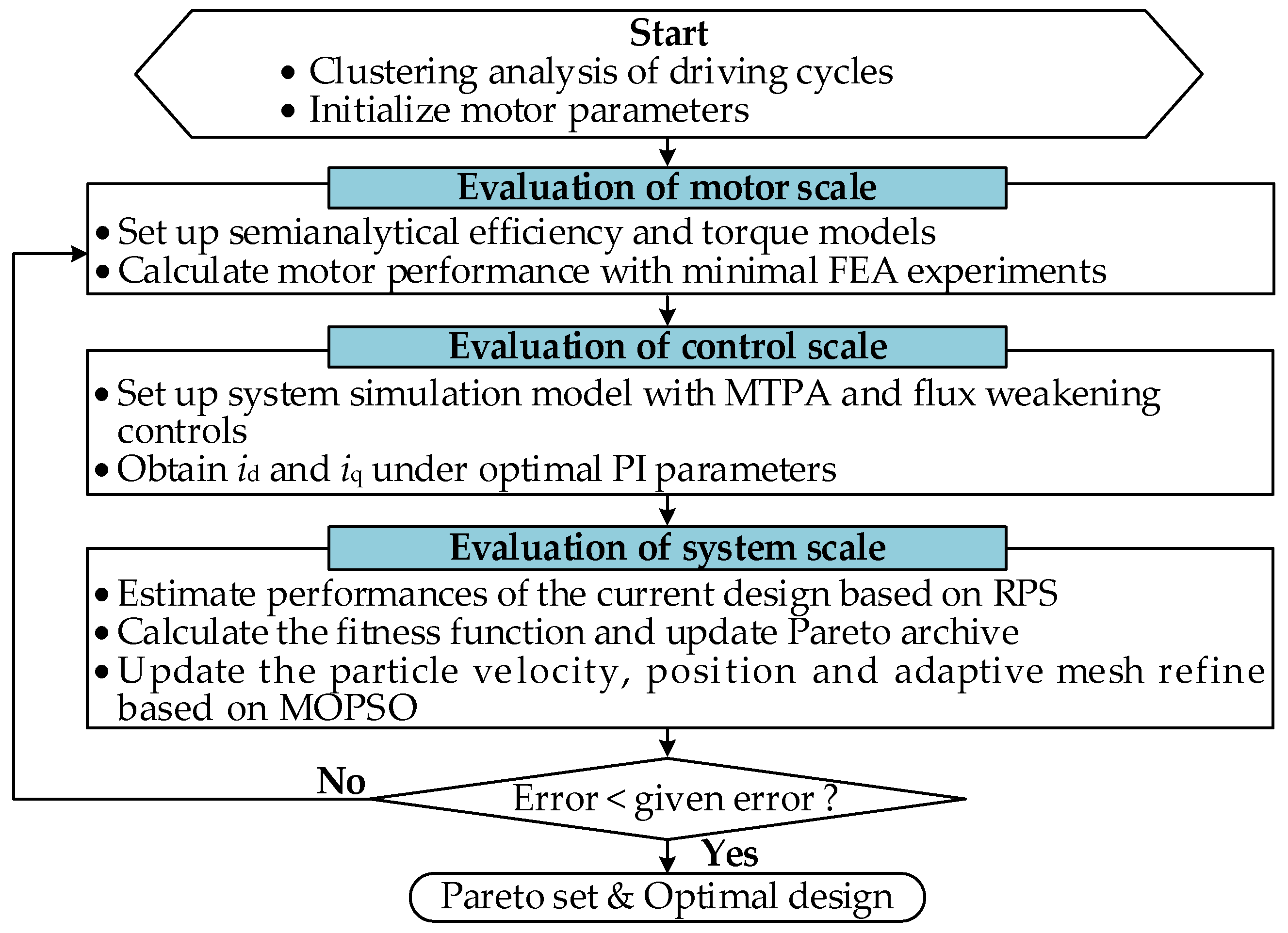
The overall optimization procedure is represented in Figure 1, which includes the following four steps.
Step 1: Analyze the driving conditions of EVs and make a preliminary design for the motor. The K-means clustering algorithm is used to identify the RPs of the motor for evaluating the performance of the motor in the whole driving cycle of EVs.
Step 2: Establish the semianalytical models and evaluate the steady performance of the motor on the motor scale. The optimal parameters of the motor are selected by sensitivity analysis.
Step 3: Evaluate the dynamic performance of the motor on the control scale with respect to the nonlinear factors given by the motor characteristic parameters. The full-speed domain control strategy is considered to meet the requirements of low-speed starting and high-speed cruising for the proposed IPMSM driving motor.
Step 4: Performance evaluation of the system scale based on the fitness function and obtaining the optimal design with MOPSO. When the result satisfies the iterative stop condition, the Pareto solution is output. Otherwise, the motor parameters are updated based on the MOPSO and then returned to Step 2.
2.2. Clustering Analysis of Driving Cycles
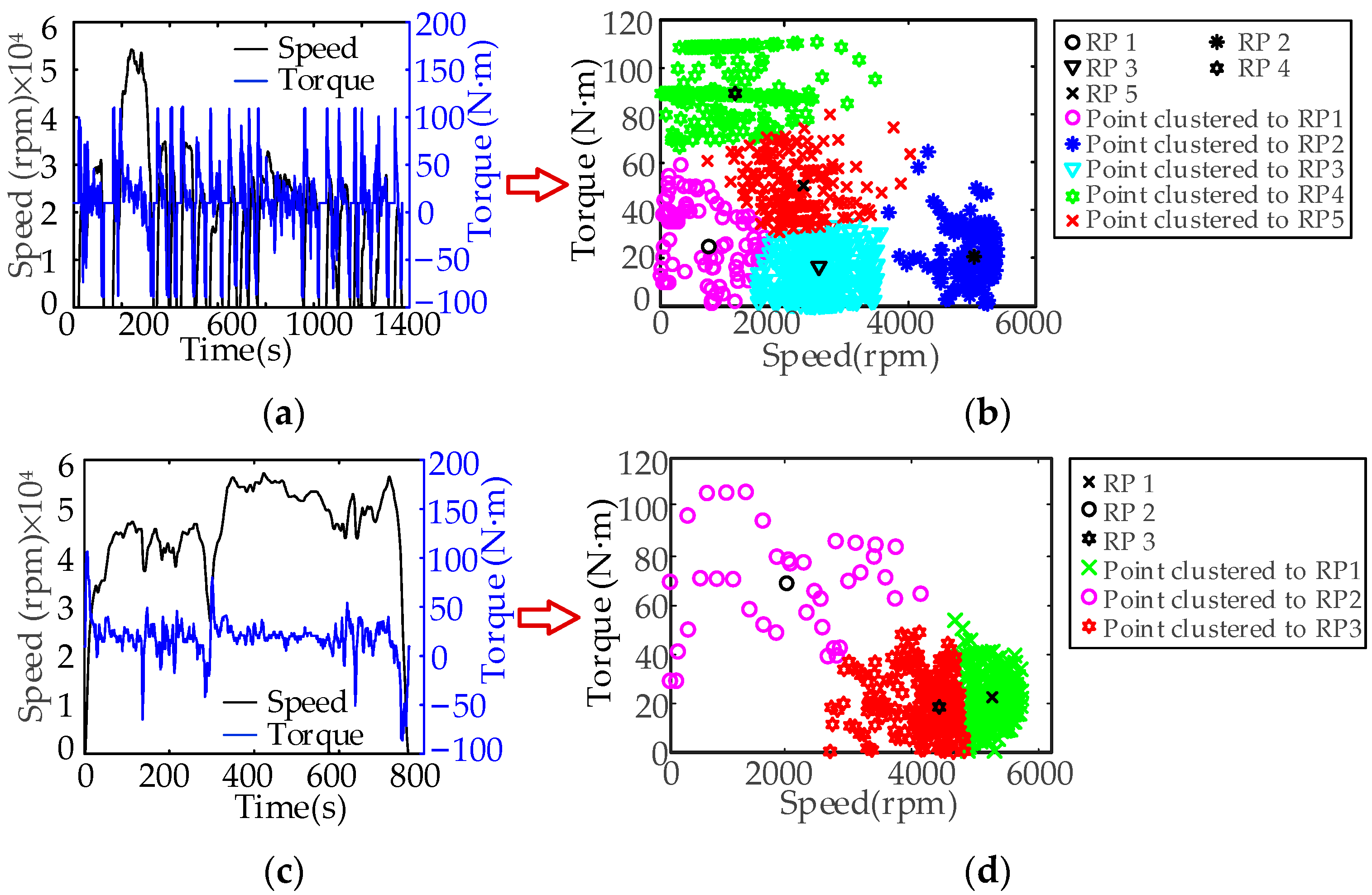
There are three case studies proposed in this paper, which are optimizations at the rated operation point, under the urban dynamometer driving schedule (UDDS), and the highway fuel economy test (HWFET). To improve the optimization efficiency, the K-means clustering method is used to analyze driving cycles [24,26], which splits the torque-speed profile obtained from the driving cycle data into different groups considering the position and density of the operating points on the plane. Euclidean distance is used to determine the similarity between samples; therefore, the cluster Si and its centroid li can be determined iteratively as follows:
The iteration repeats until the centroid of each cluster no longer changes. The cluster number k is determined based on the sum of the distances of the load points to their corresponding cluster centroid, and the cluster centroid is selected as the RP of motor optimization. In this way, the two specific driving cycles shown in Figure 2a,c can be partitioned into several clusters, as shown in Figure 2b,d. Moreover, the RPs and their energy weights are listed in Table 2. It can be found that the motor operating conditions are mostly located in the low-speed or low-torque region in UDDS, and the motor runs less in the conditions of high speed or heavy load. Meanwhile, the motor operating conditions are mostly located in the high-speed and low-torque regions of HFET. Therefore, the clusters and the number of RPs determined by the proposed clustering analysis are different for the two driving cycles, which will be used for the subsequent optimization design.
2.3. Optimization Algorithm and Fitness Function
The multi-objective PSO algorithm is utilized to obtain the optimal design, which includes adaptive mesh generation based on the roulette algorithm and global best updating as presented in [34].
In order to improve the vehicle range and driving comfort, two objectives are considered: maximize the driving cycle efficiency and minimize the torque ripple. Efficiency is the most important target for EV motors, which has a great influence on vehicle range and comfort, especially considering the current constraints of battery technology faced by vehicles. Maximum driving cycle efficiency can ensure the maximum efficiency of the drive system in the driving cycle. Likewise, the torque ripple is another key factor influencing the performance of the EV motor, which can lead to electromagnetic noise and vibration, affect vehicle comfort, and shorten the service life of the power train. Accordingly, the design objectives could be written as
where x is the optimization variable, the subscript j represents the RP j, and m is the total RP number.
Furthermore, the fitness function can be defined as
3. System-Scale Optimization of Drive Systems
For system-scale optimization, it is crucial to investigate the perfect cooperation of the motor and its controller synchronously. A design example with the semianalytical efficiency model and torque model of IPMSMs and a full-speed domain vector controller is investigated in this section.
3.1. Optimization Model for Motor Level
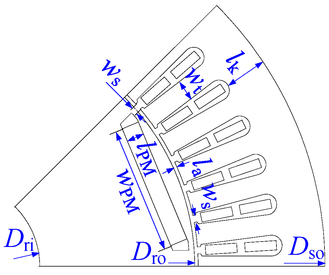
The investigated motor is parameterized as shown in Figure 3, where five independent design variables x1, x2, x3, x4, and x5 are selected and are listed in Table 3. They are the air gap, tooth width, slot width, permanent magnet width, and yoke thickness, respectively. Therefore, x = [x1, x2, x3, x4]T. It should be noted that the outer and inner diameters and the stack length are fixed [34] throughout the optimization process to meet the maximum installation space shown in Table 3.
3.1.1. Semianalytical Torque Model and Efficacy Model of IPMSMs
For each RP with a specific torque and speed, motor performance is evaluated by semianalytical models based on FEA results to balance accuracy and computation cost. Considering the saturation, cross coupling, and spatial harmonics of IPMSMs, the torque T is derived through the co-energy method [26] as follows:
where the subscribed d and q represent variables under the d-axis and q-axis.
It can be noted that there are three torque components in (6), which take torque ripple components T2 and T3 into consideration compared with the traditional torque equation, which only considers the average torque T1.
Moreover, the magnetic density inside the driving motor core is usually non-sinusoidal and rich in harmonics. Additionally, the two magnetization modes, alternating and rotating, will make the variation trends of the magnetic density trajectory completely different. In order to consider the effects of alternating magnetization, rotating magnetization, and magnetic field harmonics, the iron losses PFe of each RP are calculated by the magnetic density orthogonal decomposition model [21] as follows:
where h, or the subscript h, represents the number of magnetic density harmonics, and hm is the total harmonic number.
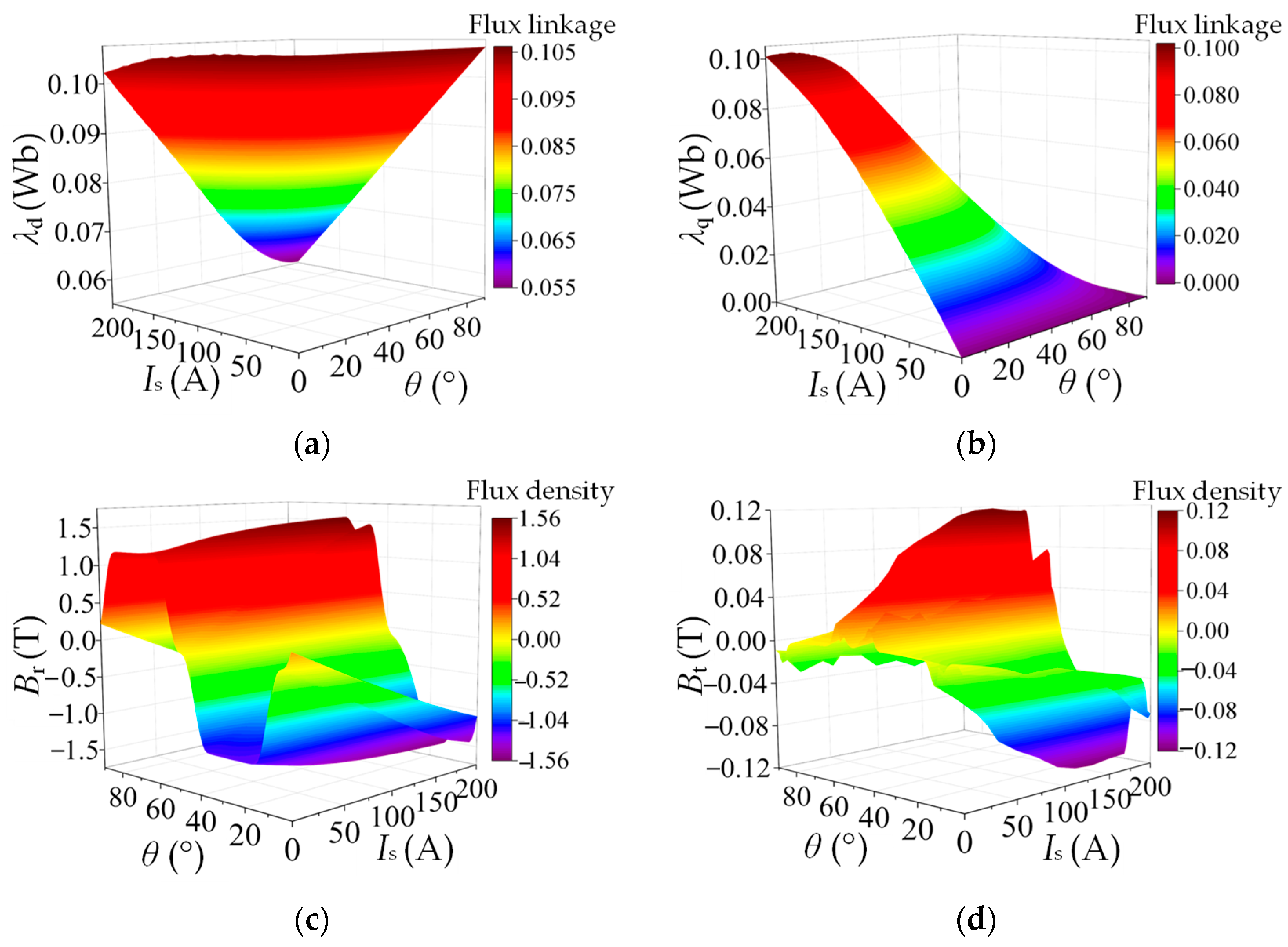
The λd, λq, Br, and Bt in analytical expressions (6) and (7) are calculated using computationally efficient FEA [26], which is the so-called semianalytical model. According to the magnetic and electric symmetry and periodicity of the considered IPMSM, when n position samples are selected and flux linkage of winding and flux density of iron core are calculated by n magnetostatics FEA of 1/8 model, there will be another 5n samples reconstructing by post-processing techniques, which is much more time-saving than FEA. Figure 4 shows the reconstructed results of λd, λq, Br, and Bt, which are used to set up the efficiency model and torque model of IPMSMs. Figure 4a,b presents the variation of λd and λq with stator phase current amplitude Is and rotor angle θ, where the rainbow color maps the flux linkage value. Figure 4c,d present the variation of Br and Bt with stator current and rotor angle in the stator teeth, where the rainbow color maps the flux density value.
3.1.2. Sensitivity Analysis of Optimization Parameters
In this paper, the Taguchi method [35] is adopted to analyze the parameter sensitivity to save computation costs for the following global optimization. The orthogonal table selects four horizontal values for each factor as shown in Table 4, which include row number 16, factor number 5, and level number 4, and can be expressed as L16(45). Considering the geometric constraints of the motor structure, the range of values for each parameter above is specified.
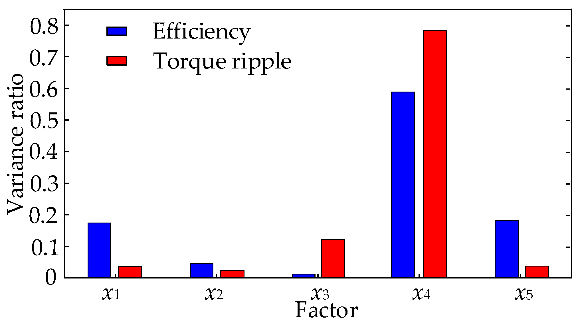
The sensitivity analysis method [35] is considered an effective approach to analyzing the significance of design variables. And the sensitivity calculation model S(O) in this paper can be expressed as
Based on (8), the effects of the selected five variables on the optimization objectives can be evaluated effectively. Figure 5 shows the sensitivity results. It can be seen that the factors x4 and x5 have great impacts on efficiency, and the factors x3 and x4 have great influences on torque ripple. Consequently, x3, x4, and x5 are comprehensively considered as optimization variables for the following optimization design.
3.2. Optimization Model for Control Level
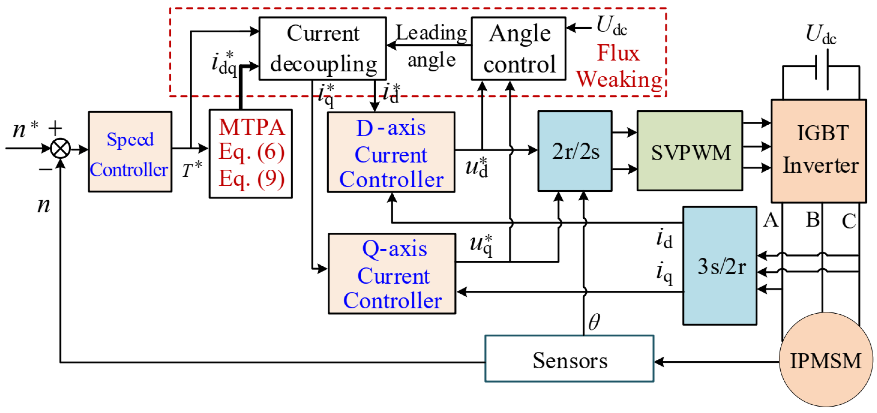
The response current of the motor under different operating conditions is related to the control strategy and the limits of the inverter bus voltage. A full-speed domain vector controller is adapted to meet the requirements of low-speed starting and high-speed cruising for the proposed IPMSM driving motor. In order to optimize the performance of the motor under different operating conditions, MTPA and flux-weakening control are used in this paper to meet the requirements of EVs. The control block is shown in Figure 6.
When the load is given and the motor terminal voltage does not reach the limit with the speed below base speed, the IPMSM adopts the MTPA control strategy and runs at the MTPA trajectory. As shown in Figure 6, in this MTPA mode, by comparing the real speed n with the speed demand n*, the torque demand T* could be obtained from the speed controller and input into the MTPA control part. And then, the current demand idq* can be solved from torque Equations (6) and (9). If the motor operates in MTPA mode, d-axis and q-axis current demand id*, iq* are decoupled from idq* and sent directly to the d-axis current controller and the q-axis current controller, respectively. Subsequently, the voltage demands ud*, uq* are obtained, and through the 2r/2s transformation and SVPWM module, they are finally turned into the switching signal to control the IGBT inverter.
When the speed demand is higher, the motor provides more torque to accelerate the rotor. At the early stage of speed regulation, the motor does not reach the base speed. However, as the motor voltage reaches its limit shown in (10), the motor speed approaches the base speed, and the speed loop saturates with the maximum given current. Therefore, the flux-weakening control strategy is adopted to redistribute the current in the dq axis through the leading angle so that the speed loop exits the saturation state and the motor torque meets the load. As shown in Figure 6, in this flux weakening mode, the leading angle δ is calculated from the angle controller by comparing the bus voltage Udc with the motor voltage. And the d-axis and q-axis current demand id*, iq* are redistributed by the current decoupling module according to δ as (11). It can be found that the flux-weakening control can increase the motor torque and expand the operating range in comparison with the MTPA control at the same motor speed.
where the motor stator resistance is neglected, and ulim is the limited value of motor phase voltage.
As described above, the speed demand is converted into torque demand by the speed controller, and the current demand is converted into voltage demand by two current controllers. In the implementation, the three PI controllers shown in Figure 6 have the form
In the whole optimization process, motor parameters and operating points change frequently, which means the fixed PI controller based on classical control theory could not satisfy the optimization demand. Therefore, to ensure that the performance evaluation of each motor scheme is carried out under the same optimal control level, two parameters α and β are optimized in the control level with the minimum control error as follows:
where t is the calculation time, and e(t) is the instantaneous response error [36].
4. Discussion and Optimization Results
4.1. Optimization Results
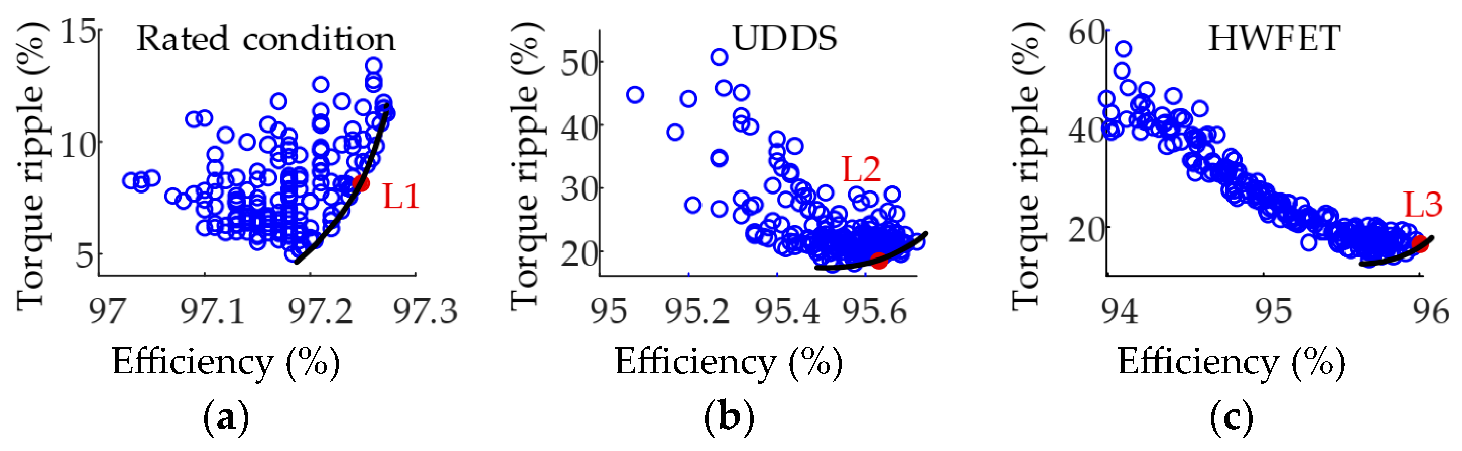
According to the optimization procedure shown in Figure 1, after determining the value of representative currents of RPs under different operating conditions, the system’s performance could be evaluated based on the fitness function, and MOPSO is used to obtain the optimal design. To illustrate the optimistic effect, the optimized motor scheme designed by the proposed optimization method will be compared with that designed by the single operation point optimization method in this section. The results of multi-objective optimization are shown in Figure 7. Figure 7a–c shows the Pareto solution set optimized by the rated operation point optimization method and the proposed optimization method under UDDS and HWFET, respectively. The black curves in these three figures are the Pareto optimal fronts for each optimization design. Each solution in the Pareto front solution set is optimal. Hence, the optimal motor scheme could be selected from this Pareto front solution set by the decision maker. Based on the VIKOR model [37], which is a multi-attribute decision-making method, the optimal solution could be selected according to (14).
where η and Tr are the efficiency and torque ripple corresponding to the current scheme, and the subscript max and min represent the maximum and minimum values of the corresponding variables. v1 and v2 are weight coefficients of two objectives, which depend on the will and preference of decision-makers, and are 0.55 and 0.45, respectively, in this paper.
In this way, three optimal motor schemes are selected and marked as red points in Figure 7. The motor scheme designed by the rated operation point optimization method is termed L1. The motor scheme designed by the proposed optimization method under UDDS is termed L2, and that optimized under HWFET is termed L3.
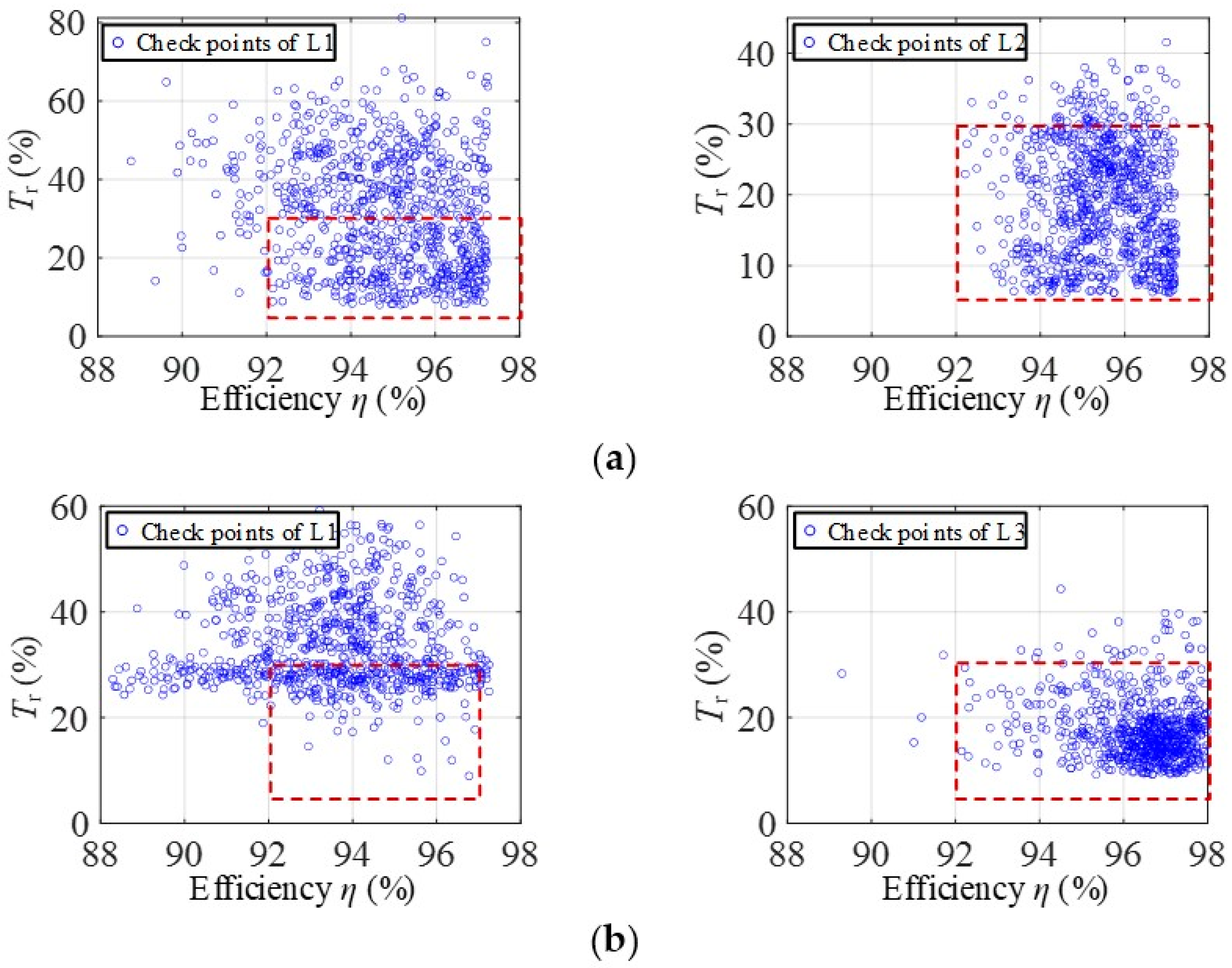
The values of the optimal variables and objective performance of the three motor schemes are listed in Table 5. Furthermore, their performances under different driving cycles are shown in Figure 8. The area in the red dotted box in Figure 8 is defined as the sweet region with high efficiency and low torque ripple, where 92% < Tr < 98% and 5% < η < 30%. Figure 8a shows the performance evaluation of L1 and L2 under UDDS. It can be observed that the motor optimized at the rated point (L1) has about 40% of the operation points falling into the sweet region, and this ratio is about 90% for the motor optimized under UDDS (L2). Figure 8b shows the performance evaluation of L1 and L3 under HWFET. It can be seen that L1 has about 20% of the operation points falling into the sweet region, and this ratio is over 90% for the motor optimized under HWFET (L3). Therefore, it can be concluded that the sweet region can be expanded by the proposed system-scale optimization, considering driving cycles.
4.2. Performance Evaluation by Experiments
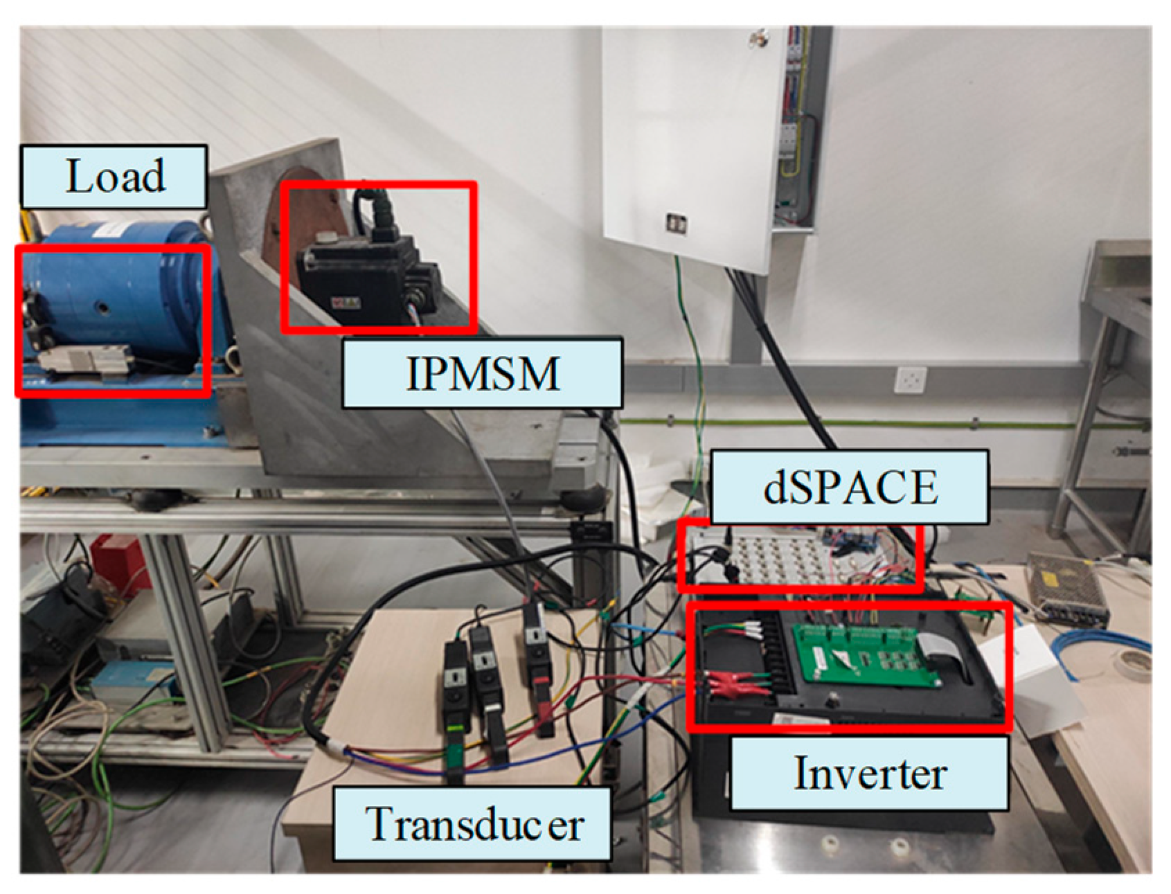
To further prove the effectiveness of the optimization method described above, an IPMSM prototype is tested on the experimental platform shown in Figure 9, which is based on the dSPACE controller. The magnetic powder brake is used to provide various load torques, and a dynamic torque sensor is used to measure dynamic torque and speed. The target motor is used to power an A0 class pure EV, which adopts UDDS as the main test specification for emissions certification and fuel economy performance testing. Therefore, L2 shown in Table 5 is chosen to be tested as the prototype, which is optimized under UDDS. Meanwhile, the UDDS driving cycle is carried out to conduct the motor performance evaluation.
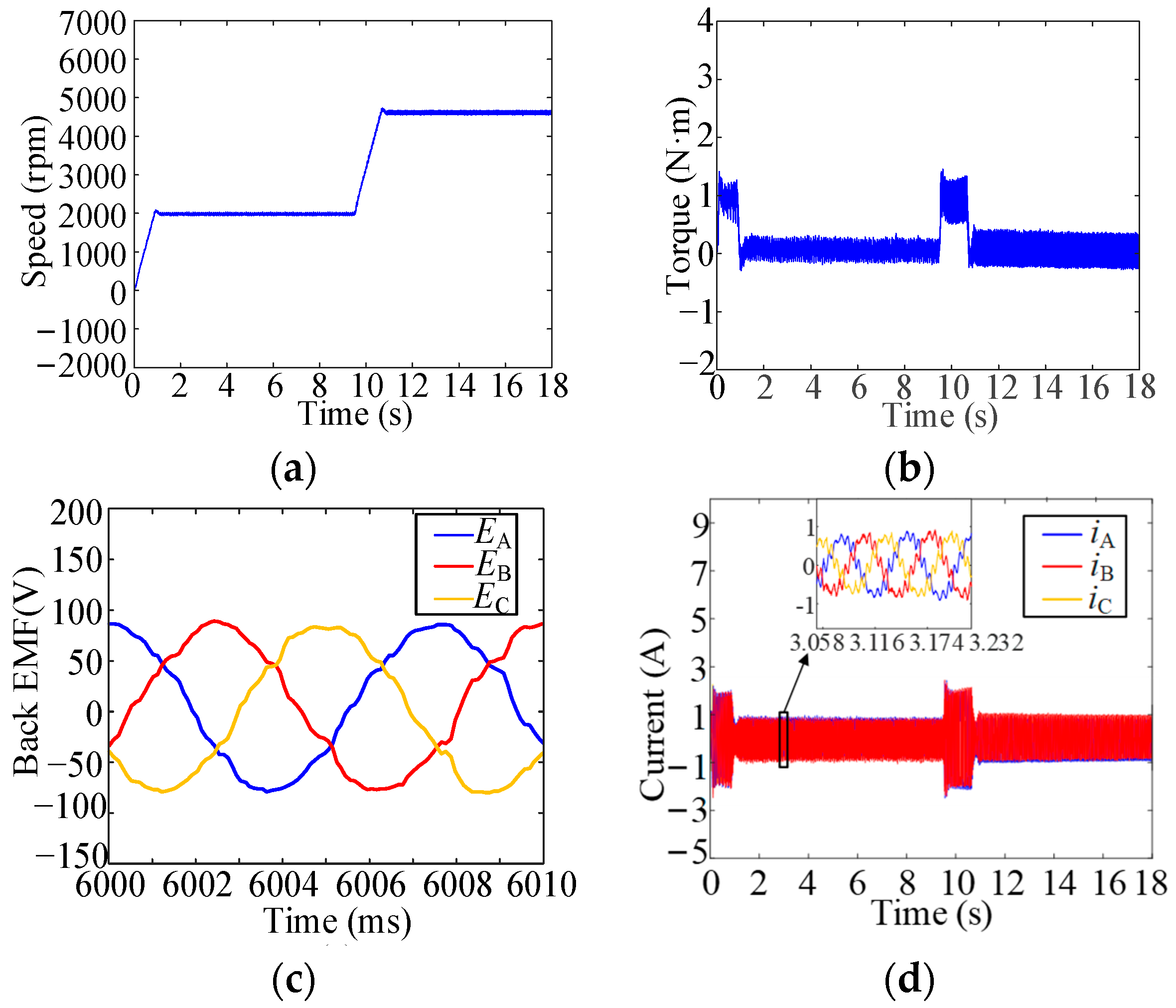
Firstly, the no-load performance of the proposed IPMSM is tested, and the results are shown in Figure 10. In Figure 10a, it can be observed that the IPMSM can quickly follow the given speed during the starting or speed switching process. And Figure 10b shows the torque ripple at no load is less than ±0.2 N·m, which demonstrates the good design of cogging torque. From Figure 10c, it can be seen that its three-phase back EMFs are sinusoidal and symmetric. Moreover, the no-load current is smaller than 1A to provide no-load loss, as shown in Figure 10d. The changes in the above curves are consistent with the changes in motor working conditions, and the motor speed regulation effect shows the feasibility of the proposed control system.
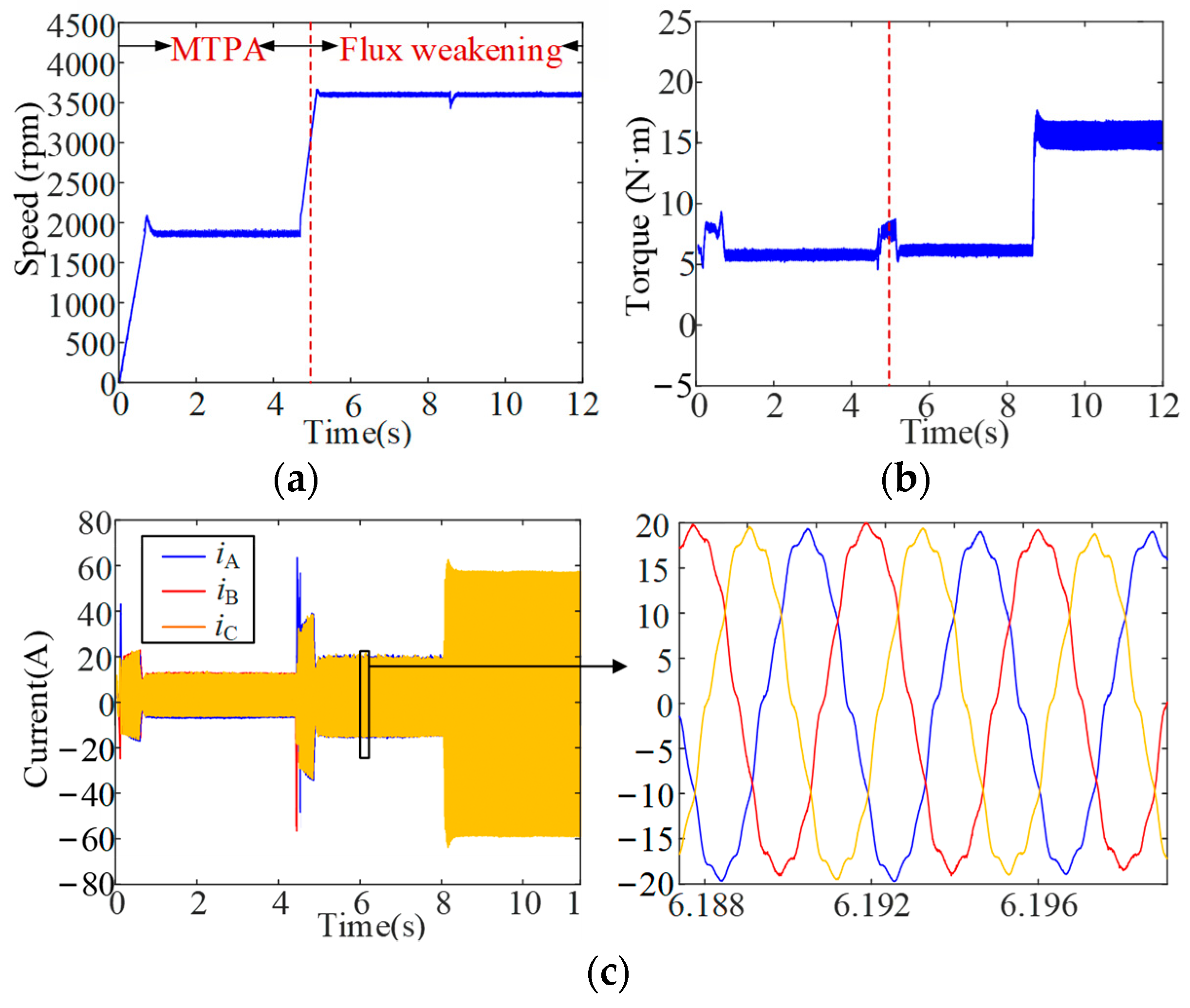
Moreover, the loaded performance of the proposed IPMSM under MTPA and flux weakening control is tested, and the results are shown in Figure 11. It can be seen from Figure 11a,b that the motor driving modes can be switched from MTPA mode to flux weakening mode at about 5 s to expand its high-speed carrying capacity. With the flux weakening control under constant power operation, more negative id is applied to the IPMSM to achieve the same torque requirements as the MTPA shown in Figure 11c. In Figure 11a, it can be seen that the IPMSM can quickly follow the given speed at starting, speed switching, or load-changing working conditions. Moreover, the torque ripple at 2000 rpm with 5 N·m is about ±1 N·m; it is similar at 3500 rpm with 5 N·m; and it is about ±3 N·m at 3500 rpm with 15 N·m, which is shown in Figure 11b. Generally, torque ripples in the two modes are about 20%, which agrees with the results in Table 5. Furthermore, the three-phase currents shown in Figure 11c are sinusoidal and symmetric, which also shows the effectiveness of the proposed control system.
In order to further verify the effectiveness of the proposed optimization method, the prototype is tested under the five RPs of UDDS. The measured efficiency and torque ripple of the prototype with the proposed control system are compared with the calculated results from the optimization process, which are listed in Table 6. The calculated results of efficiency shown in Table 6 are obtained according to the data in Table 2 and Table 5, where the input power is calculated by 2πnT/60 from Table 2 and the output power is approximately equal to the sum of the input power, PFe, and PCu in Table 5. Meanwhile, the calculated results of torque ripple shown in Table 6 are the same as Tr in Table 5. It can be observed that the measured results are almost in accordance with the optimized results. The error of efficiency is within 8%, and the maximum error of torque ripple is 20%. These errors are mainly due to the inaccurate estimation of losses and vibrations caused by mechanical factors such as wind wear and bearing in simulations. In spite of this, it can still greatly reflect the effectiveness of the proposed system-scale optimization design method, considering driving cycles.
5. Conclusions
In this paper, a system-scale multi-objective optimization methodology for driving motors based on the clustering technique under different operating conditions is proposed for electric vehicle applications. The clustering approach has been introduced to identify energy weights and RPs in the torque-speed profile for two vehicle driving cycles. To evaluate the effectiveness of the system-scale optimization design of the driving motor, a comparative study has been carried out based on the semianalytical efficiency model and torque model of IPMSMs, where the motor was optimized for UDDS, HWFET, and the rated operating point. Finally, a prototype of IPMSM with an MPTA-flux weakening controller was investigated to verify the proposed method. From the discussion, the following conclusions could be drawn:
First, compared with the optimization design under the rated operation point, the solution from the proposed optimization considering driving cycles has a larger sweet region with higher efficiency and lower torque ripple.
Second, the control parameters are considered in the proposed system-scale optimization as well as the motor parameters, which can ensure the system’s dynamic performances and are valuable for engineering batch production. Third, the proposed clustering optimization of driving motors considering inverter control strategy could well be applied for the rapid development of serialized motors in other applications, e.g., ship propulsion motors and robot motors.
The future work will be extended to more structural forms of motors with more diverse control strategies, e.g., axial-flux PMSM with direct torque control. Moreover, the multidisciplinary approach for system-scale optimization will be investigated in the following, which will consider the effects of thermal and mechanical factors from the perspective of practical engineering applications.
Author Contributions
Resources, S.Y.; Writing—original draft, J.B.; Writing—review & editing, J.D. All authors have read and agreed to the published version of the manuscript.
Funding
This research was funded by the Natural Science Foundation of China, grant number 52277065, and the National Key R&D Program of China, grant number 2020YFA0710500.
Institutional Review Board Statement
Not applicable.
Informed Consent Statement
Not applicable.
Data Availability Statement
Not applicable.
Conflicts of Interest
The authors declare no conflict of interest.
Nomenclature
| Br | Radial magnetic density component | Ploss | Motor power loss |
| Bt | Tangential magnetic density component | Pout | Motor output power |
| d | Total level number | PFe | Iron loss |
| f | Magnetic field alternates frequency | PCu | Copper loss |
| is | Stator phase current | Rs | Phase resistance |
| J | Moment of inertia | Ts | Sampling period |
| ks | Fill factor of winding | Tr | Motor torque ripple |
| Kc | Eddy current loss coefficient | ulim | Motor phase voltage limitation |
| Ke | Additional loss coefficient | w | Energy weights |
| Ky | Hysteresis loss coefficient | W′m | Co-energy |
| Ksp | Proportion coefficient of speed controller | Wm | Stored energy |
| Ksi | Integration coefficient of speed controller | zi | Data point of sample i |
| Kip_d | Proportion coefficient of d-axis current controller | Centroid of sample i in the tth iteration | |
| Kii_d | Integration coefficient of d-axis current controller | Cluster of sample i in the tth iteration | |
| Kip_q | Proportion coefficient of q-axis current controller | Average motor performance of factor O at level i | |
| Kii_q | Integration coefficient of q-axis current controller | δ | Angle between the current vector and the d-axis |
| nmax | Motor maximum speed | θ | Rotor position |
| nN | Motor rated speed | λ | Flux linkage |
| p | Pole pair number | λpm | Permanent magnet flux linkage |
| pt | Overall mean of motor performance data | Ω | Rotor mechanical angular velocity |
References
- Cui, W.; Ren, L.; Zhou, J.; Zhang, Q. A new IPMSM with Hybrid rotor structure for electrical vehicle with reduced magnet loss. IEEE Trans. Magn. 2022, 58, 1. [Google Scholar] [CrossRef]
- Geethanjali, S.; Vijayakumar, K. Testing and implementation of dual way DC-DC converter for electric vehicle power train system. IEICE Electron. Express 2022, 19, 20220343. [Google Scholar] [CrossRef]
- Zhao, X.; Kou, B.; Huang, C.; Zhang, L. A reverse-salient permanent magnet synchronous motor for electric vehicles considering operating conditions. IEEE Trans. Energy Convers. 2023, 38, 262–272. [Google Scholar] [CrossRef]
- Xu, Y.; Ai, M.; Xu, Z.; Liu, W.; Wang, Y. Research on interior permanent magnet synchronous motor based on performance matching of electric bus. IEEE Trans. Appl. Supercond. 2021, 31, 8. [Google Scholar] [CrossRef]
- Liu, J.; Liang, Y.; Yang, P. Research on novel flat wire transposed winding of pmsm for electric vehicle. IEEE Trans. Transp. Electrif. 2023, 9, 771–781. [Google Scholar] [CrossRef]
- Sun, X.; Shi, Z.; Cai, Y.; Lei, G.; Guo, Y.; Zhu, J. Driving-Cycle-oriented design optimization of a permanent magnet hub motor drive system for a Four-Wheel-Drive electric vehicle. IEEE Trans. Transp. Electrif. 2020, 6, 1115. [Google Scholar] [CrossRef]
- Sun, X.; Hu, C.; Zhu, J.; Wang, S.; Zhou, W.; Yang, Z.; Lei, G.; Li, K.; Zhu, B.; Guo, Y. MPTC for PMSMs of EVs with multi-motor driven system considering optimal energy allocation. IEEE Trans. Magn. 2019, 55, 6. [Google Scholar] [CrossRef]
- Chen, Q.; Fan, X.; Liu, G.; Xu, L.; Xu, M. Regulation of high-efficiency region in permanent magnet machines according to a given driving cycle. IEEE Trans. Magn. 2017, 53, 1. [Google Scholar] [CrossRef]
- Tian, L.; Wu, L.; Huang, X.; Fang, Y. Driving range parametric analysis of electric vehicles driven by interior permanent magnet motors considering driving cycles. CES Trans. Electr. Mach. Syst. 2019, 3, 377–381. [Google Scholar] [CrossRef]
- Fatemi, A.; Demerdash, N.A.O.; Nehl, T.W.; Ionel, D.M. Large-scale design optimization of PM machines over a target operating cycle. IEEE Trans. Ind. Appl. 2016, 52, 3772–3782. [Google Scholar] [CrossRef]
- Sarigiannidis, A.G.; Beniakar, M.E.; Kladas, A.G. Fast adaptive evolutionary PM traction motor optimization based on electric vehicle drive cycle. IEEE Trans. Veh. Technol. 2017, 66, 5762–5774. [Google Scholar] [CrossRef]
- Polat, M.; Yildiz, A.; Akinci, R. Performance analysis and reduction of torque ripple of axial flux permanent magnet synchronous motor manufactured for electric vehicles. IEEE Trans. Magn. 2021, 57, 1. [Google Scholar] [CrossRef]
- Xue, Z.; Li, H.; Zhou, Y.; Ren, N.; Wen, W. Analytical prediction and optimization of cogging torque in surface-mounted permanent magnet machines with modified particle swarm optimization. IEEE Trans. Ind. Electron. 2017, 64, 9795–9805. [Google Scholar] [CrossRef]
- Jung, S.-W.; Yoon, J.; Choi, K.; Bang, J.; Bong, U.; Hahn, S. Comparative design study of HTS synchronous motor with inner and outer rotor type based on multi-objective optimization. IEEE Trans. Appl. Supercond. 2022, 32, 6. [Google Scholar] [CrossRef]
- Liu, X.; Hu, C.; Li, X.; Gao, J.; Huang, S. An Online data-driven multi-objective optimization of a permanent magnet linear synchronous motor. IEEE Trans. Magn. 2021, 57, 7. [Google Scholar] [CrossRef]
- Cho, S.-K.; Jung, K.-H.; Choi, J.-Y. Design optimization of interior permanent magnet synchronous motor for electric compressors of air-conditioning systems mounted on EVs and HEVs. IEEE Trans. Magn. 2018, 54, 1–5. [Google Scholar] [CrossRef]
- Zhao, W.; Yang, Z.; Liu, Y.; Wang, X. Analysis of a Novel surface-mounted permanent magnet motor with hybrid magnets for low cost and low torque pulsation. IEEE Trans. Magn. 2021, 57, 1. [Google Scholar] [CrossRef]
- Diao, K.; Sun, X.; Lei, G.; Bramerdorfer, G.; Guo, Y.; Zhu, J. System-level robust design optimization of a switched reluctance motor drive system considering multiple driving cycles. IEEE Trans. Energy Convers. 2021, 36, 348–357. [Google Scholar] [CrossRef]
- Carraro, E.; Morandin, M.; Bianchi, N. Traction PMASR motor optimization according to a given driving cycle. IEEE Trans. Ind. Appl. 2016, 52, 209. [Google Scholar] [CrossRef]
- Bernard, N.; Dang, L.; Moreau, L.; Bourguet, S. A Pre-sizing method for salient pole synchronous reluctance machines with loss minimization control for a small urban electrical vehicle considering the driving cycle. Energies 2022, 15, 9110. [Google Scholar] [CrossRef]
- Yamazaki, K.; Seto, Y. Iron loss analysis of interior permanent-magnet synchronous motors-variation of main loss factors due to driving condition. IEEE Trans. Ind. Appl. 2016, 42, 1045. [Google Scholar] [CrossRef]
- Lei, G.; Wang, T.; Zhu, J.; Guo, Y.; Wang, S. System-level design optimization method for electrical drive systems—Robust approach. IEEE Trans. Ind. Electron. 2015, 62, 4702–4713. [Google Scholar] [CrossRef]
- Zhou, X.; Zhu, X.; Wu, W.; Xiang, Z.; Liu, Y.; Quan, L. Multi-objective optimization design of variable-saliency-ratio PM motor considering driving cycles. IEEE Trans. Ind. Electron. 2021, 68, 6516. [Google Scholar] [CrossRef]
- Qiu, H.; Cui, S.; Wang, S.; Wang, Y.; Feng, M. A Clustering-Based optimization method for the driving cycle construction: A case study in fuzhou and Putian, China. IEEE Trans. Intell. Transp. Syst. 2022, 23, 18681. [Google Scholar] [CrossRef]
- Salameh, M.; Brown, I.P.; Krishnamurthy, M. Fundamental evaluation of data clustering approaches for driving Cycle-Based machine design optimization. IEEE Trans. Transp. Electrif. 2019, 5, 1395. [Google Scholar] [CrossRef]
- Chen, H.; Liu, X.; Demerdash, N.A.; El-Refaie, A.M.; Chen, Z.; He, J. Computationally efficient optimization of a Five-Phase Flux-Switching PM machine under different operating conditions. IEEE Trans. Veh. Technol. 2019, 68, 6495. [Google Scholar] [CrossRef]
- Lai, C.; Feng, G.; Iyer, K.L.V.; Mukherjee, K.; Kar, N.C. Genetic Algorithm-Based current optimization for torque ripple reduction of interior PMSMs. IEEE Trans. Ind. Appl. 2017, 53, 4493–4503. [Google Scholar] [CrossRef]
- Jia, H.; Cheng, M.; Hua, W.; Zhao, W.; Li, W. Torque ripple suppression in flux-switching PM motor by harmonic current injection based on voltage Space-Vector modulation. IEEE Trans. Magn. 2020, 46, 1527–1530. [Google Scholar] [CrossRef]
- Zhang, R.; Yin, Z.; Du, N.; Liu, J.; Tong, X. Robust Adaptive current control of a 1.2-MW Direct-Drive PMSM for traction drives based on internal model control with disturbance observer. IEEE Trans. Transp. Electrif. 2021, 7, 1466–1481. [Google Scholar] [CrossRef]
- De Klerk, M.L.; Saha, A.K. A Comprehensive Review of advanced traction motor control techniques suitable for electric vehicle applications. IEEE Access 2021, 9, 125080–125108. [Google Scholar] [CrossRef]
- Deng, T.; Su, Z.; Lin, J.; Tang, P.; Chen, X.; Liu, P. Advanced angle field weakening control strategy of permanent magnet synchronous motor. IEEE Trans. Veh. Technol. 2019, 68, 3424–3435. [Google Scholar] [CrossRef]
- Alzayed, M.; Chaoui, H.; Farajpour, Y. Dynamic direct voltage MTPA current sensorless drives for interior PMSM-Based electric vehicles. IEEE Trans. Veh. Technol. 2023, 72, 3175–3185. [Google Scholar] [CrossRef]
- Song, C.-H.; Song, I.-S.; Shin, H.-S.; Lee, C.-H.; Kim, K.-C. A Design of IPMSM for High-Power electric vehicles with wide-field-weakening control region. IEEE Trans. Magn. 2022, 58, 2. [Google Scholar] [CrossRef]
- Yuan, S.; Du, J.; Wei, Y. Optimization of Permanent Magnet Machine for Electric Vehicles Considering the Control Strategy and Inverter. In Proceedings of the 2020 23rd International Conference on Electrical Machines and Systems (ICEMS), Melaka, Malaysia, 24–27 November 2020. [Google Scholar] [CrossRef]
- He, J.; Li, G.; Zhou, R.; Wang, Q. Optimization of Permanent-Magnet spherical motor based on taguchi method. IEEE Trans. Magn. 2020, 56, 2. [Google Scholar] [CrossRef]
- Abdo, Q.M.; Ewad, H.; Mohamed, K.A. Optimized PID Controller for Single Area Thermal Power System Based on Time Varying Acceleration Coefficients Particle Swarm optimization. In Proceedings of the 2020 International Conference on Computer, Control, Electrical, and Electronics Engineering, Khartoum, Sudan, 26 February–1 March 2021; pp. 1–5. [Google Scholar] [CrossRef]
- Falch, L.; de Silva, C.W. Improvement of VIKOR method with application to Multi-Objective design problems. Int. J. Inf. Technol. Decis. Mak. 2023, 22, 777–802. [Google Scholar] [CrossRef]
Figure 1.
Framework of the proposed system-scale optimization for driving motors targeting driving cycles.
Figure 1.
Framework of the proposed system-scale optimization for driving motors targeting driving cycles.

Figure 2.
Driving cycle clustering results. (a) Speed curve of UDDS. (b) Torque-speed curve of UDDS. (c) Speed curve of HWFET. (d) Torque-speed curve of HWFET.
Figure 2.
Driving cycle clustering results. (a) Speed curve of UDDS. (b) Torque-speed curve of UDDS. (c) Speed curve of HWFET. (d) Torque-speed curve of HWFET.

Figure 3.
Parameterized model of the investigated IPMSM.

Figure 4.
Computationally efficient FEA results for semianalytical models. (a) λd. (b) λq. (c) Br in stator teeth. (d) Bt in stator teeth.
Figure 4.
Computationally efficient FEA results for semianalytical models. (a) λd. (b) λq. (c) Br in stator teeth. (d) Bt in stator teeth.

Figure 5.
Variance ratio of motor parameters.

Figure 6.
Control block diagram of the full-speed domain vector controller.

Figure 7.
Motor optimization results under different working conditions. (a) Underrated condition. (b) Under UDDS. (c) Under HWFET. The blue dots are optimization solutions and black curves are Pareto optimal fronts.
Figure 7.
Motor optimization results under different working conditions. (a) Underrated condition. (b) Under UDDS. (c) Under HWFET. The blue dots are optimization solutions and black curves are Pareto optimal fronts.

Figure 8.
Performance evaluations of three motor schemes under different working conditions. (a) UDDS. (b) HWFET. The area in the red-dotted box is the sweet region.
Figure 8.
Performance evaluations of three motor schemes under different working conditions. (a) UDDS. (b) HWFET. The area in the red-dotted box is the sweet region.

Figure 9.
Experimentation platform of the IPMSM prototype.

Figure 10.
Experimental results at no load. (a) Speed. (b) Torque. (c) Back EMF. (d) Current.

Figure 11.
Experimental results are loaded. (a) Speed. (b) Torque. (c) Current.


Table 1.
Specification of the investigated EV.
| Parameter | Value | Parameter | Value |
|---|---|---|---|
| Vehicle mass | 1100 kg | Radius of wheels | 0.308 m |
| Maximum gradeability | 20% | Maximum climbing speed | 20 km/h |
| Motor rated speed | 3000 rpm | Motor maximum speed | 8000 rpm |
| Acceleration time | <10 s for 0~50 km/h, <15 s for 50~100 km/h | ||
Table 2.
Specification of RPs in two driving cycles.
| RPs | Speed (rpm) | Torque (N·m) | w (%) | |
|---|---|---|---|---|
| UDDS | 1 | 738 | 27 | 7.8 |
| 2 | 4934 | 21.66 | 9.9 | |
| 3 | 2546 | 14 | 46.26 | |
| 4 | 1126 | 91 | 18.63 | |
| 5 | 2157 | 50 | 17.37 | |
| HWFET | 1 | 5308 | 21 | 47 |
| 2 | 2051 | 68 | 5 | |
| 3 | 4269 | 20 | 48 |
Table 3.
Design parameters of the investigated IPMSM.
| Parameter | Value | Parameter | Value | Parameter | Value |
|---|---|---|---|---|---|
| Dso (mm) | 210 | le (mm) | 153 | wPM (mm) | x4 |
| lPM (mm) | 5 | la (mm) | x1 | lk (mm) | x5 |
| Dri (mm) | 48 | wt (mm) | x2 | α | x6 |
| Dro (mm) | 136 | ws (mm) | x3 | β | x7 |
Table 4.
Orthogonal table of motor factors.
| Number | x1 | x2 | x3 | x4 | x5 |
|---|---|---|---|---|---|
| 1 | 0.93 | 5.59 | 1.87 | 32.4 | 11.2 |
| 2 | 1.2 | 5.59 | 2.13 | 35.87 | 9.6 |
| 3 | 1.07 | 5.83 | 2.13 | 34.13 | 14.4 |
| 4 | 1.07 | 5.83 | 2.13 | 32.4 | 12.8 |
| 5 | 0.8 | 5.36 | 1.6 | 32.4 | 9.6 |
| 6 | 1.2 | 5.36 | 1.87 | 37.6 | 12.8 |
| 7 | 0.8 | 5.83 | 1.87 | 35.87 | 14.4 |
| 8 | 1.07 | 5.36 | 2.4 | 35.87 | 11.2 |
| 9 | 1.07 | 6.06 | 1.87 | 34.13 | 9.6 |
| 10 | 1.07 | 5.59 | 1.6 | 37.6 | 14.4 |
| 11 | 1.2 | 5.83 | 1.6 | 34.13 | 11.2 |
| 12 | 0.8 | 5.59 | 2.4 | 34.13 | 12.8 |
| 13 | 0.8 | 6.06 | 2.13 | 37.6 | 11.2 |
| 14 | 0.93 | 5.83 | 2.4 | 37.6 | 9.6 |
| 15 | 1.2 | 6.06 | 2.4 | 32.4 | 14.4 |
| 16 | 0.93 | 6.06 | 1.87 | 35.87 | 12.8 |
Table 5.
Objective performances and optimal variables.
| L1 | L2 | L3 | ||
|---|---|---|---|---|
| RPs | IP (A), PFe (W), PCu (W), Tr (%) | |||
| UDDS | 1 | 29.8, 39.35, 53.25, 21 | 31.56, 34.24, 59.76, 14 | none |
| 2 | 66.8, 355.11, 268, 35 | 53.37, 324.2, 171.24, 21 | ||
| 3 | 15.26, 178.09, 14, 42 | 16.32, 155.81, 16, 25 | ||
| 4 | 92.74, 80.5, 515.9, 10 | 96.55, 76.14, 559.18, 8 | ||
| 5 | 52.6, 154.5, 165.8, 15 | 55.18, 140.78, 182.7, 11 | ||
| HWFET | 1 | 82.8, 381, 411.25, 38 | none | 82.75, 59.48, 325, 15 |
| 2 | 71, 153.22, 303.4, 14 | 71.11, 76.4, 135.76, 10 | ||
| 3 | 34.39, 327, 71.27, 28 | 34.39, 21.14, 296.67, 17 | ||
| Rated | 97.3, 284, 567.9, 7.91 | 100.75, 274, 608.92, 6.1 | 103, 268.32, 638, 9.26 | |
| Optimal results | x1, x2, x3, x4, x5, x6, x7 | |||
| 0.8, 5.5, 1.5, 36, 14, 8750, 6500 | 0.8, 5.5, 1.7, 33.5, 14.5, 7854, 6280 | 0.8, 5.5, 1.7, 32.5, 14.5, 7525, 7500 | ||
Table 6.
Optimization parameters of the investigated IPMSM.
| L2 | RPs | Efficiency (%) | Torque Ripple (%) | ||||
|---|---|---|---|---|---|---|---|
| Calculated Result | Experimental Result | Error * | Calculated Result | Experimental Result | Error * | ||
| UDDS | 1 | 95.7 | 91 | 5.15 | 14 | 15 | 6.67 |
| 2 | 95.7 | 89 | 7.59 | 21 | 20 | −5 | |
| 3 | 95.6 | 89 | 7.41 | 25 | 23 | −8.7 | |
| 4 | 94.4 | 89 | 6.07 | 8 | 10 | 20 | |
| 5 | 97.2 | 91 | 6.83 | 11 | 13 | 15 | |
* Error = (Calculated result-Experimental result)/Experimental result.
Disclaimer/Publisher’s Note: The statements, opinions and data contained in all publications are solely those of the individual author(s) and contributor(s) and not of MDPI and/or the editor(s). MDPI and/or the editor(s) disclaim responsibility for any injury to people or property resulting from any ideas, methods, instructions or products referred to in the content. |
© 2023 by the authors. Licensee MDPI, Basel, Switzerland. This article is an open access article distributed under the terms and conditions of the Creative Commons Attribution (CC BY) license (https://creativecommons.org/licenses/by/4.0/).
Share and Cite
MDPI and ACS Style
Bu, J.; Yuan, S.; Du, J. Clustering Optimization of IPMSM for Electric Vehicles: Considering Inverter Control Strategy. Appl. Sci. 2023, 13, 10792. https://doi.org/10.3390/app131910792
AMA Style
Bu J, Yuan S, Du J. Clustering Optimization of IPMSM for Electric Vehicles: Considering Inverter Control Strategy. Applied Sciences. 2023; 13(19):10792. https://doi.org/10.3390/app131910792
Chicago/Turabian StyleBu, Jiabao, Shangbin Yuan, and Jinhua Du. 2023. "Clustering Optimization of IPMSM for Electric Vehicles: Considering Inverter Control Strategy" Applied Sciences 13, no. 19: 10792. https://doi.org/10.3390/app131910792
Note that from the first issue of 2016, this journal uses article numbers instead of page numbers. See further details here.