Article

Development of a Magnetic Levitation Wafer Handling Robot Transfer System with High-Accuracy and High-Cleanliness: Experimental Evaluation

Department of AI Machinery, Korea Institute of Machinery & Materials (KIMM), Daejeon 34103, Republic of Korea
*
Author to whom correspondence should be addressed.
Appl. Sci. 2023, 13(16), 9482; https://doi.org/10.3390/app13169482
Submission received: 31 July 2023 / Revised: 18 August 2023 / Accepted: 19 August 2023 / Published: 21 August 2023
(This article belongs to the Special Issue Advanced Manufacturing Technologies: Development and Prospect)

Abstract

:
Magnetic levitation can reduce particulate contamination that occurs during wafer transportation in the semiconductor manufacturing process. This technology radically eliminates contact between the wafer and the transport system, reducing friction, wear, and particle generation. Therefore, it is suitable for achieving high cleanliness in the ultra-fine line-width semiconductor production process and solving the need for particle removal in a vacuum environment. In this study, the roller and linear motion guide components of the wafer transfer system were replaced with a magnetic levitation module, and a robot arm was installed on top to transport a single wafer. A posture controller and a current controller were designed, and test equipment simulating the wafer transfer system was also manufactured and tested. Regarding mover and system identification, a sine sweep test was performed on the motion axis of the five degrees of freedom. Through the obtained system identification, it was possible to design the posture controller more precisely. Moreover, through levitation in standstill experiments and high-speed operation experiments, the wafer transport system can be used to verify dust-free high-speed transport and accurate positioning performance.

1. Introduction

As semiconductor processes continue to be refined, the requirements for the equipment used in semiconductor manufacturing are becoming increasingly demanding. Since even fine particles can directly cause defects in semiconductors, various efforts have been made to reduce particle contamination.
The main factors contributing to particle generation in wafer transport systems can be summarized as linear motion (LM) guides, belts, cables, cable bays, and lubrication [1,2]. In other words, particle generation in the wafer transport system is caused by friction, abrasion, and lubrication. Particle generation cannot be completely eliminated with contact-based transport systems. Therefore, interest in high-clean transfer systems is increasing in the field of ultra-fine semiconductor manufacturing.
Recently, in semiconductor manufacturing processes, the development of contactless delivery systems has been actively developed due to the importance of particle-free and highly accurate delivery operations [3,4,5,6]. Magnetic levitation technology is considered a highly promising alternative to meet these requirements [7]. Magnetic levitation eliminates contact in the conveying system, minimizing friction, wear, and particle generation. It can also operate stably in a vacuum environment, making it suitable for various semiconductor manufacturing processes [8]. In a study by Yamakawa et al. [9], experiments were conducted to measure the contamination of dust particles during wafer delivery in a vacuum environment. The results showed that the magnetic levitation transport system is highly beneficial for particle-free transportation and exhibits very low outgassing.
Conventional research on magnetic levitation equipment has focused on implementing stages with levitation masses within several kilograms to achieve exceptional motion control accuracy [10,11,12,13]. These advanced magnetic levitation stages hold significant promise for critical semiconductor manufacturing processes, such as photolithography, which demand nanometer-level precision [14,15].
Recently, there have been notable developments in the field, including a high-precision magnetic levitation transfer system capable of enabling long-stroke movements and transporting movers weighing more than hundreds of kilograms [16,17]. Moreover, researchers are exploring various configurations for magnetic levitation transport systems, such as attaching electromagnets and linear propulsion motors to the moving part or fixed rails [18,19,20]. Additionally, real-scale prototypes are being developed to experimentally validate the effectiveness of proposed methods. These efforts aim to further enhance the capabilities and applications of magnetic levitation technology in the semiconductor manufacturing industry.
In this study, magnetic levitation was applied to a wafer transport system by replacing the roller and LM guide. A multi-joint wafer handling robot was installed at the top of the wafer transfer system, and this robot performed precise work, enabling rapid and accurate transfer even under harsh working conditions with extremely high acceleration and deceleration. To ensure control performance even under these challenging operational conditions, a robust controller has been designed based on loop shaping method. Therefore, a controller that precisely controls the five degrees of freedom (5-DOF) of the wafer transfer system was designed to enable high-speed transfer and precise position control by replacing wheels with magnetic levitation modules installed at the four corners. In addition, the stability and reliability of the magnetic levitation was experimentally verified to confirm its applicability in the actual manufacturing environment with a real-scale prototype of a wafer transfer system.
This paper is organized as follows. In Section 2, the system configuration of a magnetic levitation wafer transfer system is presented. The system modeling and control design of magnetic levitation are proposed, and the experimental evaluation of a real-scale prototype of a magnetic levitation wafer transfer system is presented in Section 3. In Section 4, a discussion is presented.

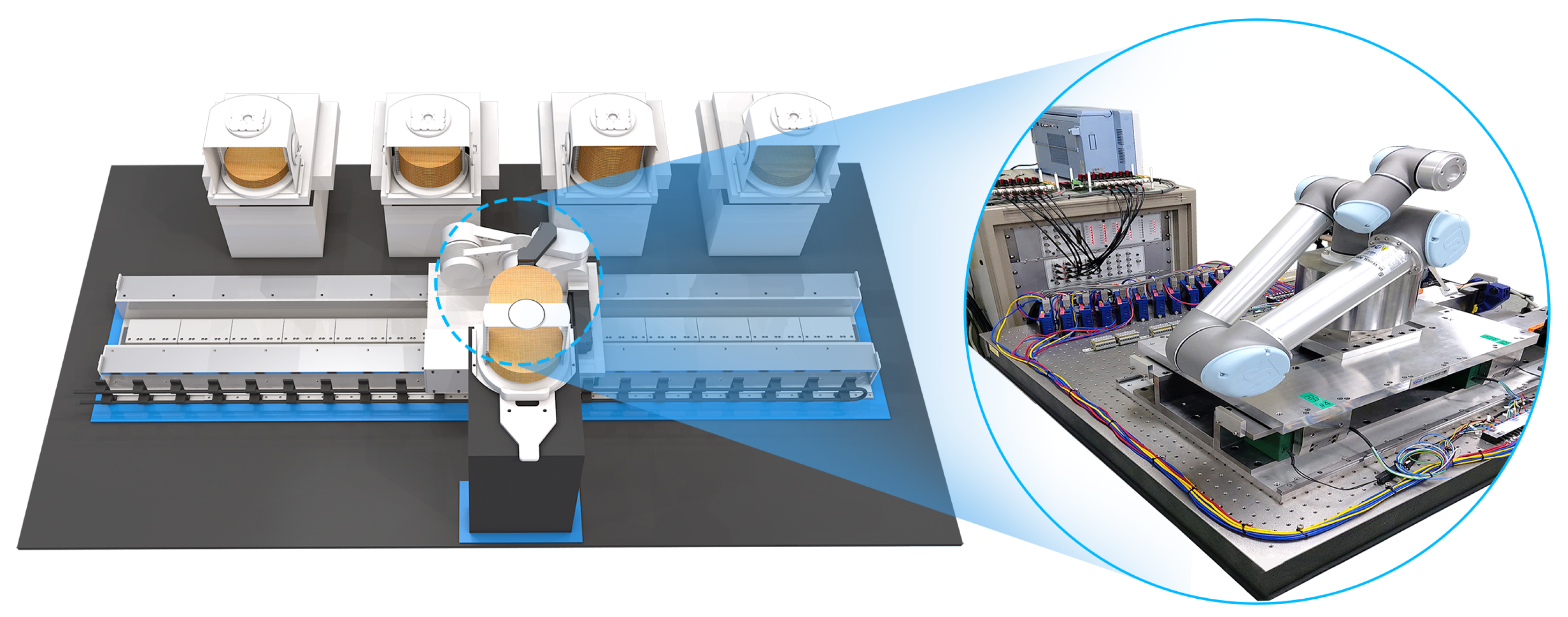
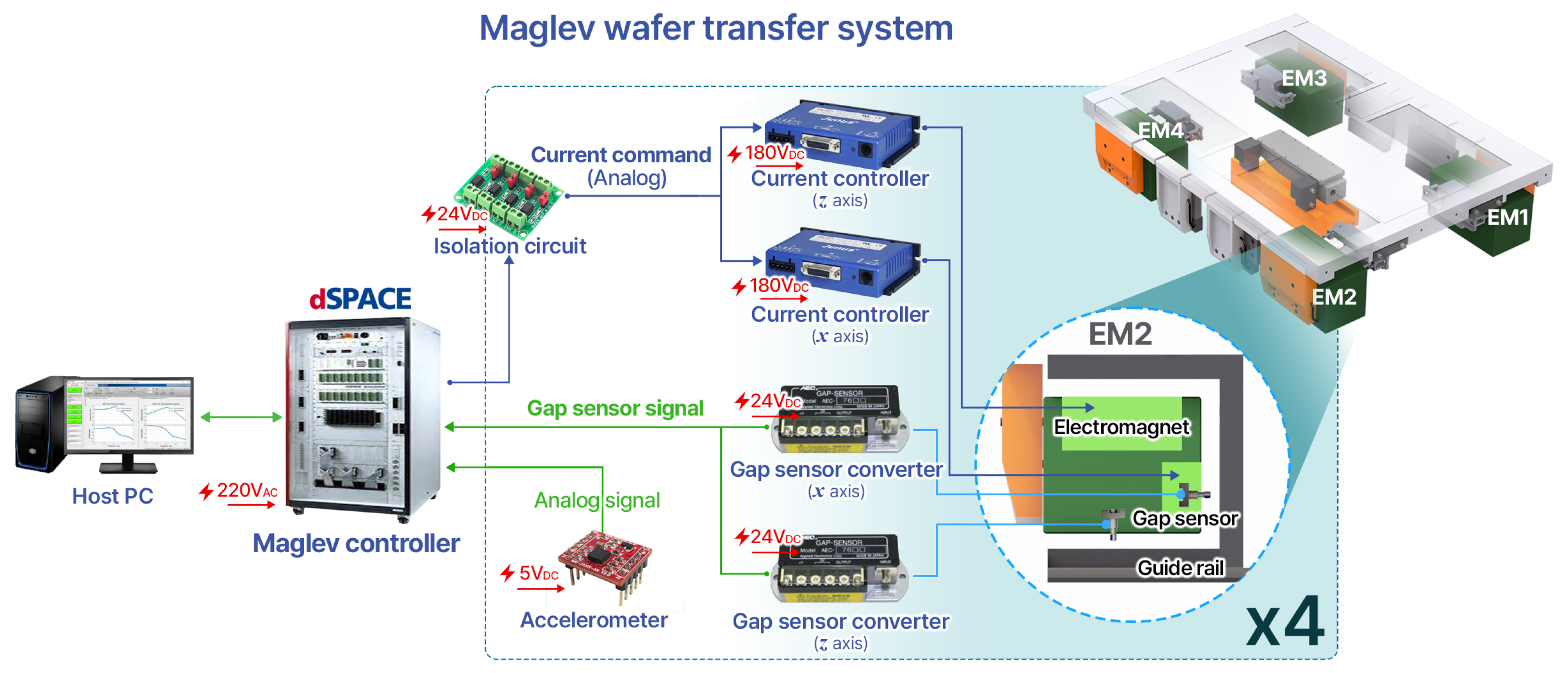
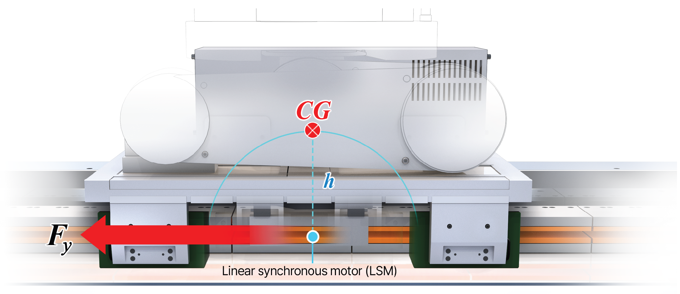
2. System Configuration

The magnetic levitation wafer transfer system controls the 5-DOF motion, excluding propulsion, and the linear synchronous motor (LSM) handles the linear drive. Figure 1 illustrates the concept of the wafer transfer platform, multi-joint robot arm, and magnetic levitation transfer system. The robot arm is installed on the top, and the magnetic levitation units and propulsion system are positioned at the bottom relative to the aluminum base. On the left side of the circled diagram, the current controller, the posture controller, the isolation board, and the oscilloscope for real-time magnetic levitation control and measurement are located. To mitigate the influence of wire tension from electromagnets (EMs) and gap sensors, the wires were configured with extended lengths to ensure minimal force transmission. Consequently, the impact of wire tension can be considered negligible. In the forthcoming system operation, electric power will be provided through the wireless power supply method, allowing the effects resulting from wiring to be disregarded.
To control magnetic levitation, magnetic levitation modules are placed at the four corners of the aluminum base. As shown in Figure 2a, four magnetic levitation modules generate four attractive forces ( f 1 f 4 ) for vertical control and four attractive forces ( f 5 f 8 ) for horizontal control. Figure 2b illustrates four gap sensors ( c 1 c 4 ) for measuring the z-axis airgaps and four gap sensors ( c 5 c 8 ) for the x-axis airgaps measurement. Based on the structural analysis of the base, the center of gravity (CG) of the mover can be calculated, and the 5-DOF posture can be calculated. The posture controller generates a 5-DOF force reference ( F x , F z , M x , M y , M z ) based on the 5-DOF posture information. The generated 5-DOF force is converted into eight force ( f 1 f 8 ) reference inputs and applied to each electromagnet module.
The proposed magnetic levitation module, which includes x- and z-axis EMs and gap sensors, and a guide rail, is shown in Figure 3a. To implement the x- and z-axis EMs in a single magnetic levitation module, each flux path is orthogonalized to eliminate the effects of magnetic interference. The x-axis EM generates a closed flux loop in the X Y plane, and the z-axis EM produces a closed flux loop in the X Z plane. The z-axis EM was designed in a dual-coil configuration, and the x-axis EM was divided into three coils to enable a simultaneous reduction in backcore thickness, core volume, and weight. The maximum force required by the EM was determined through dynamic analysis by simulation. The experimental results demonstrated that the power consumption of the EM remained within 150 W during stationary levitation. Additionally, even after extended periods of operation, the temperature was maintained below 40 °C. The magnetic flux density distribution in the landing state, which is the condition for applying the maximum current of the z-axis EM, is shown in Figure 3b. In this case, the magnetic flux generated by the z-axis current constitutes a closed loop in the Z X plane, and it can be stably driven without magnetic saturation within the maximum magnetic flux density of 1.5 T. The total mass, moment of inertia, and distances from the CG to the EM modules are presented in Table 1.
To control the magnetic levitation, both a higher-level controller for posture control and a lower-level controller for current control of the EMs are necessary. Figure 4 illustrates the arrangement of power and signal lines for connecting the controllers and the test plant. The main power line of 180 V d c is supplied to the current controller, and the control power of 24 V d c is supplied to the isolation board and gap sensor converter. An additional 5 V d c power is supplied to measure the acceleration of the mover, and the acceleration sensor is placed at the center of the mover. The host PC controls the posture controller (dSPACE) using the MATLAB/Simulink-based plant model. Thanks to the utilization of a validated and user-friendly MATLAB/Simulink-based experimental environment, the development time of control systems can be significantly expedited. The force references ( f 1 f 8 ) calculated by the posture controller are converted into current commands and transmitted to the current controller, and the force of the EM is produced by the applied current of the current controller. In terms of airgap sensing, the inductive gap measuring sensor (AEC’s PU-05) has been selected. An interface board was also developed to facilitate the transmission of current references to the current controller (Copley’s JSP-180-30).

3. Magnetic Levitation Control System

3.1. System Modeling
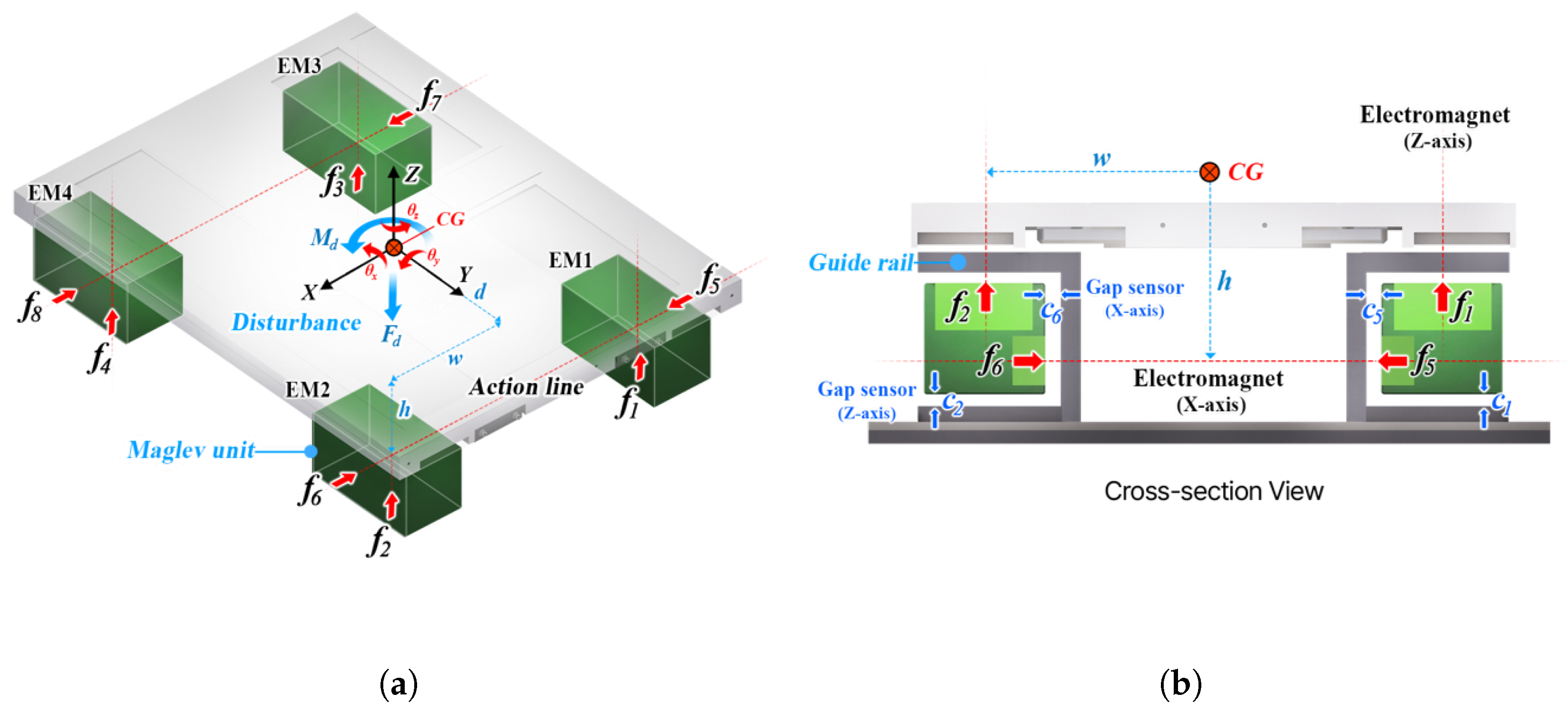
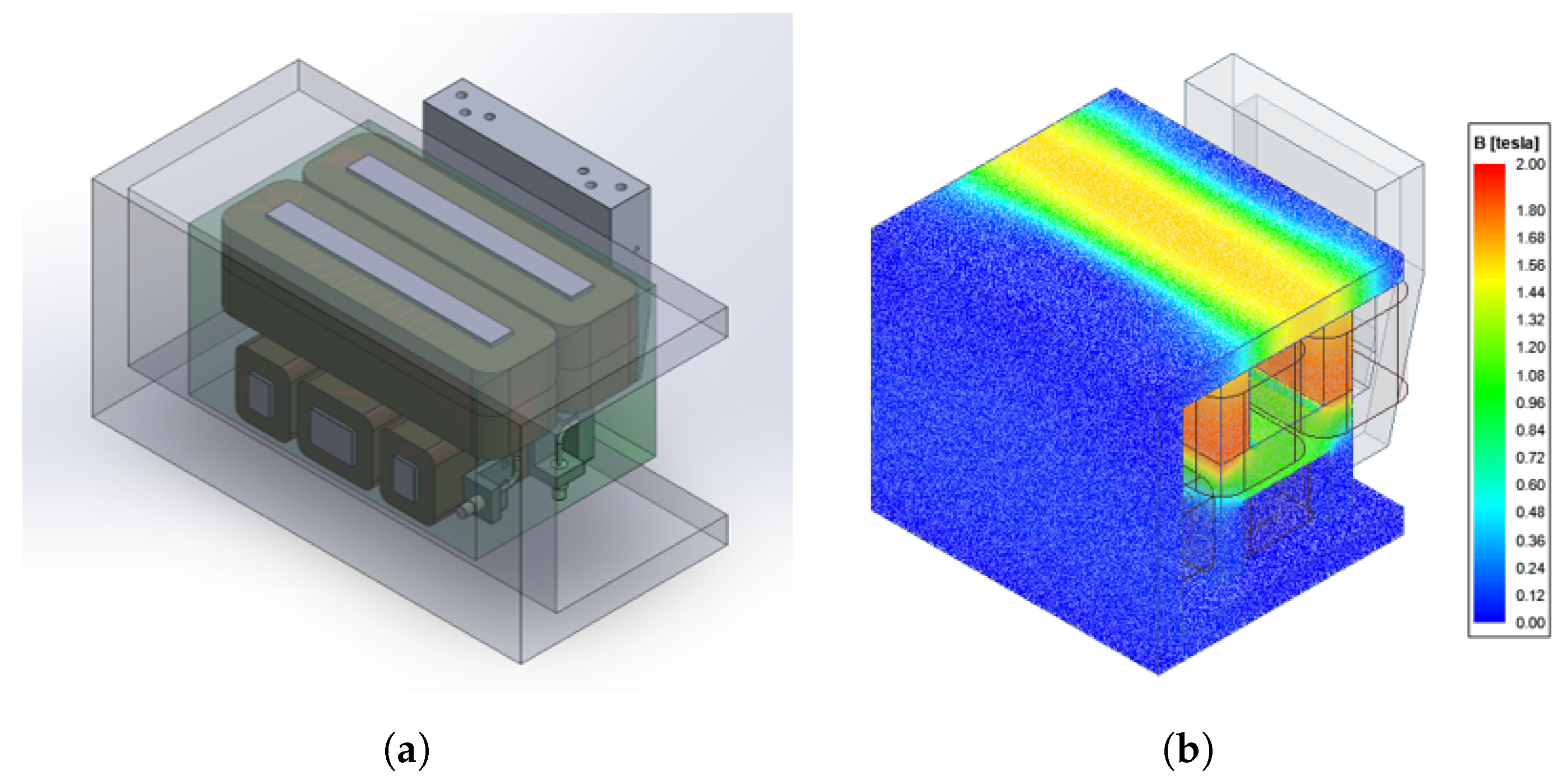
  • EM Model
    According to previous studies [21,22], the attractive force generated by the EM can be written as
    f n = μ 0 N 2 A 4 i n c n 2
    where μ 0 = 4 π × 10 7 H/m is the vacuum permeability, i is the applied current, and c is the airgap. The values of the number of turns N and pole area of EM A that are used are summarized in Table 2.
  • Dynamic Equation
    The dynamic equation of the magnetic levitation wafer transfer system can be described by Newton’s equation for translation and Euler’s equation for rotation. Newton’s equation represents the relationship between the force acting on the center of mass of a rigid body and its acceleration, while Euler’s equation represents the relationship between the moments acting on the center of mass of a rigid body and the time derivative of the angular momentum.
    F = m a M G = H ˙ G
    The developed magnetic levitation wafer transfer system is mechanically symmetric about the x- and y-axes, so the coordinate system used is the principal axes of inertia, and the products of inertia can be neglected: I x y = I x z = I y z = 0 . Therefore, the angular momentum is expressed as follows: H G = I x ω x i ^ + I y ω y j ^ + I z ω z k ^ . By substituting the time derivative of the angular momentum and the attractive force generated by EMs into Equation (2), the dynamic equation of the magnetic levitation wafer transfer system can be summarized.
    m x ¨ = f 5 f 6 + f 7 f 8 + F d x m z ¨ = f 1 + f 2 + f 3 + f 4 + F d z I x θ ¨ x ( I y I z ) θ ˙ y θ ˙ z = d ( f 1 + f 2 f 3 f 4 ) + M d x I y θ ¨ y ( I z I x ) θ ˙ z θ ˙ x = w ( f 1 f 2 + f 3 f 4 ) + h ( f 5 + f 6 f 7 + f 8 ) + M d y I z θ ¨ z ( I x I y ) θ ˙ x θ ˙ y = d ( f 5 + f 6 + f 7 f 8 ) + M d z
    The y-axis motion of the magnetic levitation wafer transfer system is controlled by an LSM, and the 5-DOF motion excluding the y-axis motion is precisely controlled by the magnetic levitation units attached to the four corners of the magnetic levitation wafer transfer system.
    To design a linear controller, the dynamic equation Equation (3) is linearized. The simulation results show that the nonlinear terms are relatively small compared to the linear terms ( I x θ ¨ x ( I y I z ) θ ˙ y θ ˙ z ). Thus, the linearized dynamic equation is sufficient for obtaining meaningful interpretation results. The linearized motion equation can be expressed in the following matrix form:
    q ¨ = M 1 B f + M 1 d = M 1 u + M 1 d
    where
    q = x z θ x θ y θ z T f = f 1 f 2 f 3 f 4 f 5 f 6 f 7 f 8 T d = F d x F d z M d x M d y M d z T M = diag m m I x I y I z B = 1 1 1 1 1 1 1 1 d d d d w w w w h h h h d d d d u = B f = u x u z u θ x u θ y u θ z T .
    The q matrix represents the movements of the 5-DOF of the magnetic levitation wafer transfer system, the f matrix represents the attractive forces generated by the EMs, the d matrix represents the disturbances, the M matrix is the inertia matrix, the B matrix represents the geometric installation information of the EMs, and the u matrix is the decoupled control input that is used to achieve a desired output.
  • Kinematics
    The 5-DOF motion of the magnetic levitation wafer transfer system is measured by the gap sensors installed at the four corners. To control the system, a process of reconstructing the 5-DOF motion based on the measured sensor signals is carried out. The motion of the electromagnet module 1 (EM1) can be expressed as r E M 1 based on the inertial reference coordinate. And, it can also be expressed as the sum of the center of gravity motion r C G and the relative motion with respect to center of gravity θ × r E M 1 / C G [23]. The relationship between the 5-DOF motion of the magnetic levitation wafer transfer system and the gap sensor measurements installed at the four corners is determined by the following kinematics.
    r E M 1 = r C G + θ × r E M 1 / C G
    For example, the relationship between the 5-DOF motion of the magnetic levitation wafer transfer system and the gap sensor measurements in EM1 is
    r E M 1 = ( x i ^ + y j ^ + z k ^ ) + ( θ x i ^ + θ y j ^ + θ z k ^ ) × ( w i ^ + d j ^ h k ^ ) = ( x h θ y d θ z ) i ^ + ( y + h θ x w θ z ) j ^ + ( z + d θ x + w θ y ) k ^
    As shown in Figure 3, the z-axis motion measured by Gap Sensor 1 in EM1 can be expressed as follows: c 1 = c 1 c 0 z = z + d θ x + w θ y . Similarly, the x-axis motion measured by Gap Sensor 5 in EM1 can be expressed as follows: c 5 = c 5 c 0 x = x + h θ y + d θ z . By repeating the same process for EM2, EM3, and EM4, the relationship between the 5-DOF motion of the magnetic levitation wafer transfer system and the gap sensor measurements installed at the four corners can be obtained as follows:
    Δ c = Tq
    where
    Δ c = Δ c 1 Δ c 2 Δ c 3 Δ c 4 Δ c 5 Δ c 6 Δ c 7 Δ c 8 T T = 1 d w 1 d w 1 d w 1 d w 1 h d 1 h d 1 h d 1 h d
    The T matrix represents the geometric installation information of the gap sensors. Conversely, the 5-DOF motion of the magnetic levitation wafer transfer system can be reconstructed from the measured gap sensor signals using the pseudo inverse.
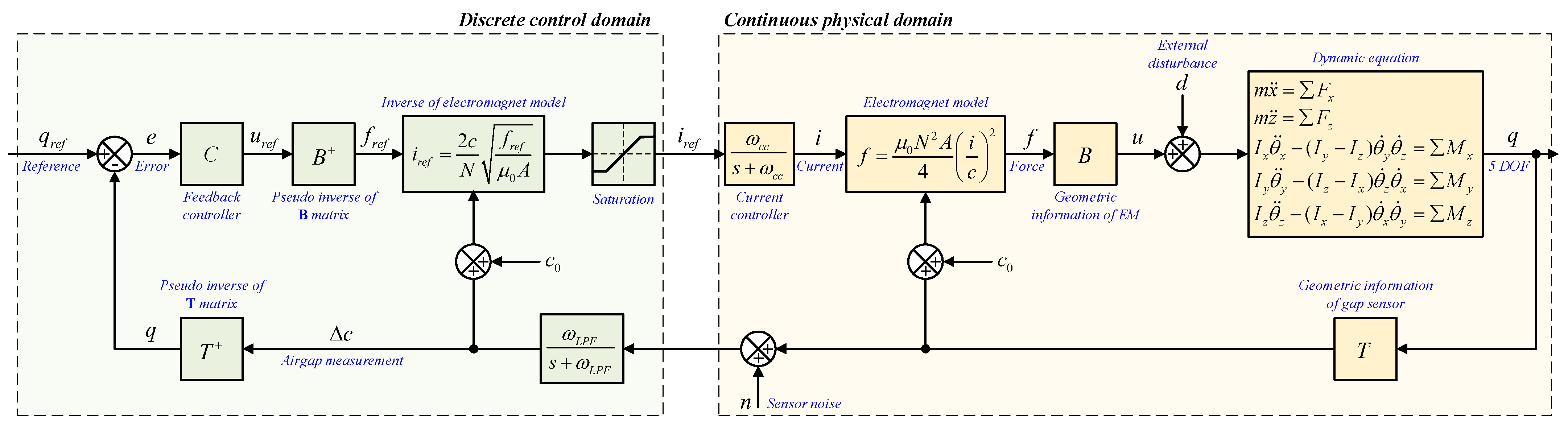
    q = T + Δ c
  • Block diagram
    Figure 5 shows the block diagram of the feedback control system of the magnetic levitation wafer transfer system. The input of the dynamic equation is the decoupled control input u and disturbance d , and the output is the 5-DOF motion q . The 5-DOF motion of the magnetic levitation wafer transfer system is measured by the gap sensors Δ c installed at the four corners, and the sensor noise is included in the measurement process. The measured sensor signal is reconstructed into the 5-DOF motion, and the difference e between the reference and the measured 5-DOF motion is calculated and utilized as the input of the feedback controller. The output of the feedback controller is the required force and momentum u ref that are used to achieve the desired 5-DOF motion. By using the pseudo inverse of the B matrix and the EM model, the required current for each EM i ref is calculated. This calculated current is utilized as the input of the current controller and affects the 5-DOF motion of the magnetic levitation transfer system through the EM model and B matrix related to the installation information of the EMs. The left green box is the discrete control part, and the right pink box is the continuous physical system.

3.2. Feedback Controller Design

Assuming that the control bandwidth of the current controller is sufficiently fast compared to the magnetic levitation control bandwidth, the sensor noise is small, and the fluctuation of the 5-DOF motion is not large so that the nonlinear term of the dynamic equation can be ignored, and the block diagram can be simplified as shown in Figure 6. Furthermore, the magnetic levitation feedback controller is designed as follows:
u = C ( q ref q )
where
C = d i a g ( C x C z C θ x C θ y C θ z )
A key feature of this controller structure is that there is no coupling term between the DOFs, so it can easily implement independent control characteristics for each DOF. In this study, a proportional–integral–derivative (PID) with a low-pass filter control structure is used. By combining the dynamic equation Equation (4) and the feedback controller Equation (9), this model can be expressed as follows by utilizing the Laplace transform.
q ¨ = M 1 C ( q ref q ) + M 1 d s 2 Q = M 1 C ( Q ref Q ) + M 1 D
The above equation can be expressed as
Q = [ s 2 I + M 1 C ] 1 M 1 C Q ref + [ s 2 I + M 1 C ] 1 M 1 D
where
C ( s ) = k p + k i 1 s + k d N s s + N
Equation (11) can be used to obtain the transfer functions for each DOF. For example, the transfer function for the x-axis is
x = # 2 # 1 x r e f + # 3 # 1 F d x
where
# 1 = m s 4 + m N s 3 + ( k p + k d N ) s 2 + ( k p N + k i ) s + k i N # 2 = ( k p + k d N ) s 2 + ( k p N + k i ) s + k i N # 3 = s 3 + N s
The equation labeled # 1 is called the characteristic equation, which reflects various feedback control characteristics such as the stability and response. In this study, the controller is designed to achieve a control bandwidth of approximately 10 Hz, a phase margin of more than 30 degrees, and a gain margin as large as possible. The feedback controller is designed to meet the desired system requirements by adjusting the control gain using the loop shaping technique. Loop shaping is a well-known systematic control system design method that can be used to achieve the desired control performance, stability, and robustness by shaping the loop transfer function of the control system [24]. In the low-frequency range, the magnitude of loop gain is closely related to control performance in terms of external disturbance attenuation and tracking performance. In the high-frequency range, the magnitude of loop gain is closely related to control performance in terms of sensor noise attenuation.
After completing the controller design on a MATLAB simulation, a sine sweep test was performed to verify that the developed feedback controller works properly in the actual physical system. The sine sweep test is an experiment that analyzes the frequency response of the developed feedback control system by examining the relationship between the input and output. In the sine sweep test, a chirp signal is added to the reference. The amplitude of the chirp signal applied was ±0.01 mm, and the frequency was set to gradually change from 0.1 Hz to 100 Hz over 300 s. During the test, the reference, error, and output were measured.
Figure 7 shows the reference and output measured by conducting a sine sweep test on the x-axis. Figure 8 shows the frequency response characteristics based on the measured reference, error, and output estimated by the MATLAB System Identification Toolbox. Figure 8a represents the frequency response curve between the reference and output, which corresponds to the complementary sensitivity function. This graph shows that the control bandwidth of the designed feedback control system is approximately 10 Hz. Figure 8b represents the frequency response curve between the error and output, which corresponds to the loop gain. This graph shows that the gain margin is infinite and that the phase margin is approximately 30 degrees. The reason for the negative gain margin is the presence of an unstable zero within the transfer function. Through various trial and error processes, the desired frequency response characteristics and satisfactory control performance were achieved. Similar processes were performed for other DOFs (z, θ x , θ y , θ z ), and feedback controllers were designed to achieve control bandwidths in the range of 10-20 Hz, similar to the x-axis case.

3.3. Experimental Evaluation

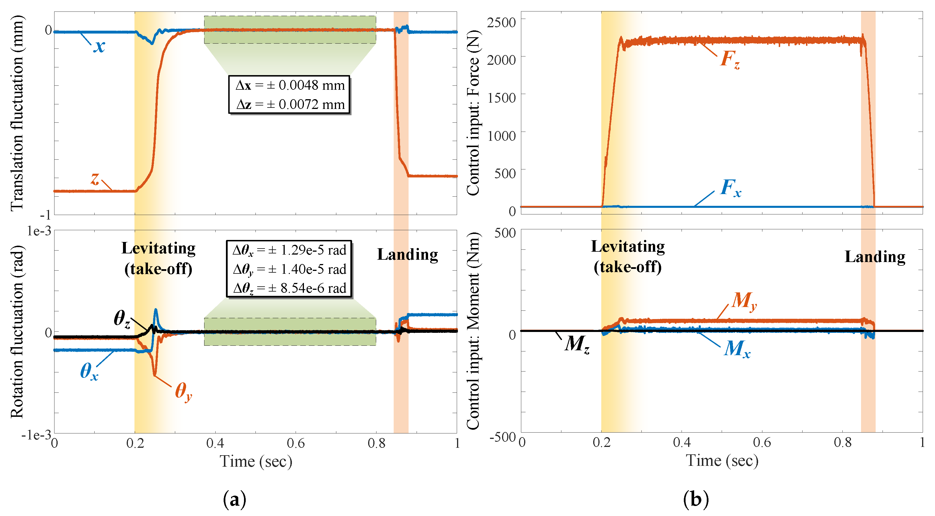
3.3.1. Magnetic Levitation at Standstill

The control performance of the developed magnetic levitation wafer transfer system was verified through experiments under various conditions. Figure 9a is the transient response characteristic result for the magnetic levitation under the conditions of the initial-take-off-landing state. In the case of a linear controller, the levitation control performance in a transient region may deteriorate since the operating point is further away from the equilibrium point. To minimize this effect, ensuring robustness against the modeling errors and ensuring sufficient relative stability, such as gain margins, are important. The control inputs for the 5-DOF motion of the system are shown in Figure 9b. To achieve a smooth transient response, the reference signal from the landing state to the levitation state was set to gradually change in the form of a ramp rather than a step. As a result, as shown in the figure, the system smoothly converges to the steady state without significant overshoot during the state transition. After the state transition is complete, the 5-DOF variation is ±0.0048 mm, ±0.0072 mm, ± 1.29 × 10 5 rad, ± 1.40 × 10 5 rad, and ± 8.54 × 10 6 rad for the x-, z-, θ x -, θ y -, and θ z -axes, respectively.
System characteristics can be analyzed based on the force and moment applied to each DOF in the steady state. For example, the weight of the system can be estimated from F z , and the CG can be estimated from the applied moment acting in the steady state. An analysis of F z confirmed that the actual weight was approximately 225 kg, similar to the design values specified in Table 2. Additionally, the analysis of M y confirms that the CG is slightly shifted in the x-direction. In fact, this system has a center of gravity deflected by approximately 20 mm in the x -direction according to the robot’s posture and mass distribution inside the control box, which were not considered during the initial design.

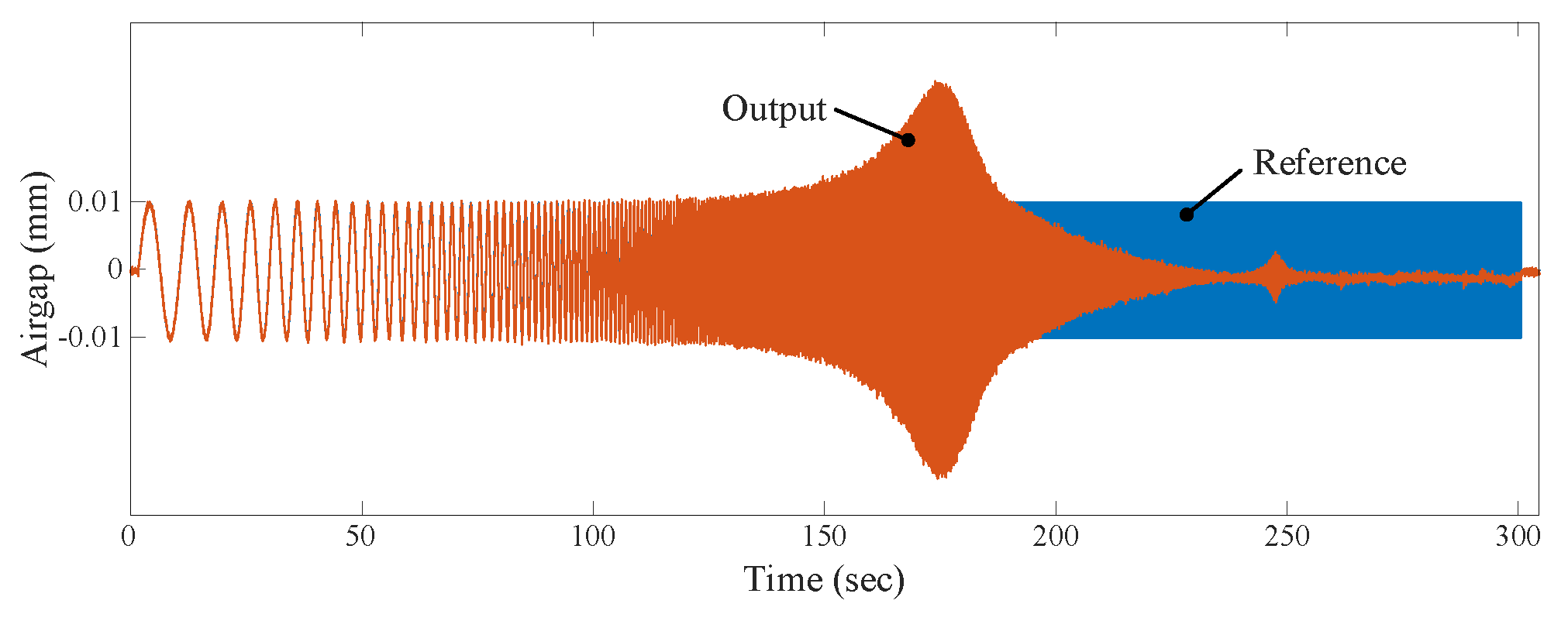
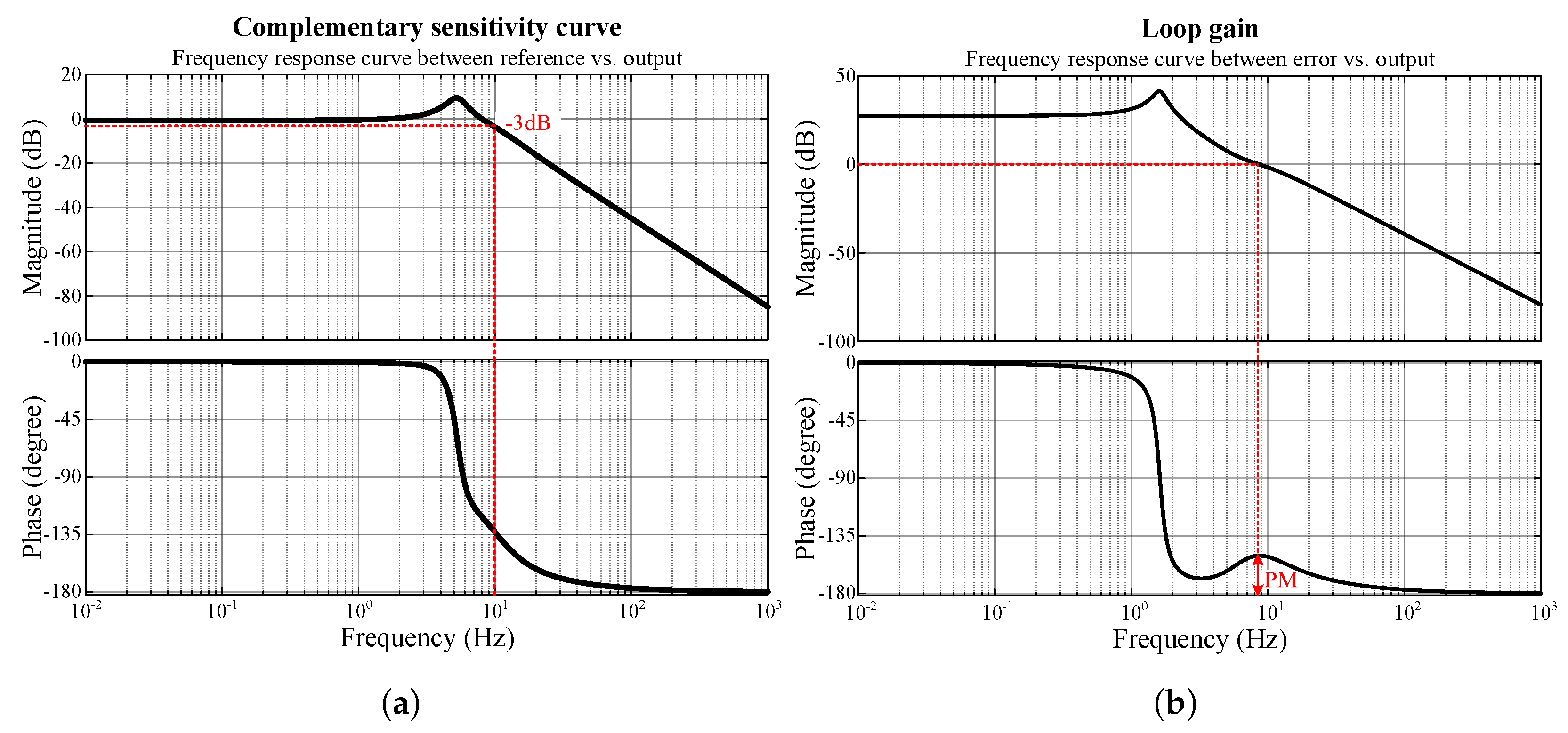
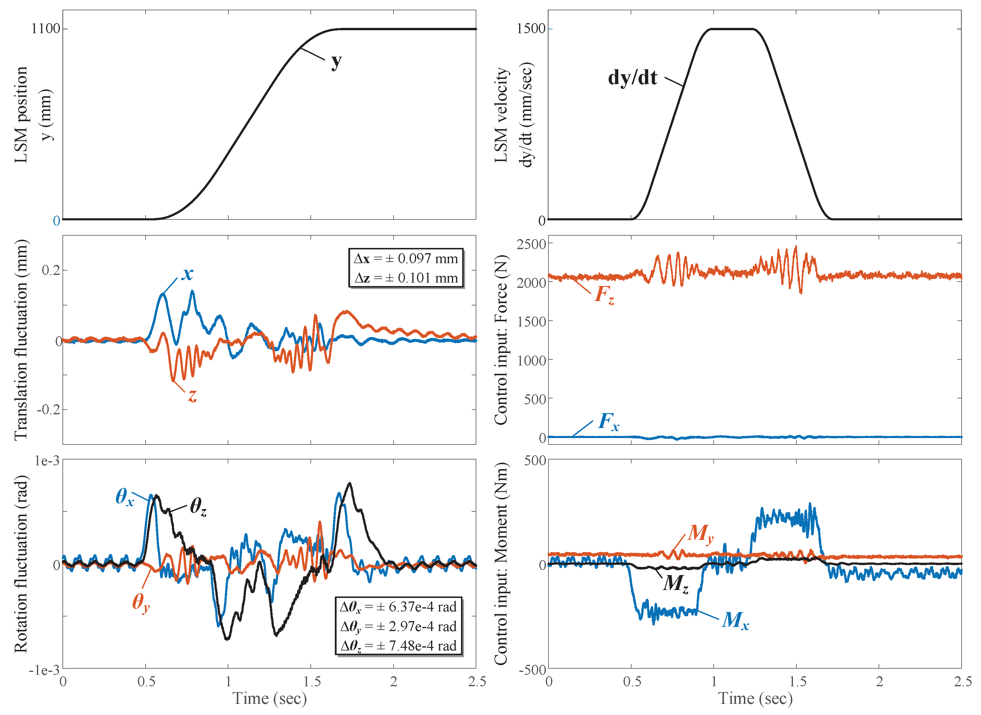
3.3.2. Magnetic Levitation under Driving Conditions

An experiment was conducted to observe the control performance of the magnetic levitation while the system maintained magnetic levitation and moved in the y-axis driven by the LSM. Figure 10 shows the 5-DOF fluctuation of the magnetic levitation wafer transfer system when it travels a distance of D = 1100 mm with an S-curve motion profile [25,26] under a maximum speed of V max = 1500 mm/s and a maximum acceleration of A max = 3060 mm/s. During the driving process, the maximum fluctuations in the x, z, θ x , θ y , and θ z -directions were ±0.097 mm, ±0.101 mm, ± 6.37 × 10 4 rad, ± 2.97 × 10 4 rad, and ± 7.48 × 10 4 rad, respectively. These results represent a very satisfactory control performance. In this system, during the acceleration and deceleration periods, inertial moments are generated due to the height difference (h) between the point in which the thrust force is generated and the center of gravity, as shown in Figure 11. This leads to significant oscillations in the θ x -direction of the magnetic levitation wafer transfer system, and these oscillations are considered external disturbances. To overcome these external disturbances, we attached an accelerometer to the moving base as shown in Figure 4, to measure the actual acceleration in the y-axis. Furthermore, we took into account the height difference between the point at which the thrust force is generated and the center of gravity, which we know in advance. By multiplying the actually measured acceleration and height difference, external disturbances were roughly predicted to minimize the effects of external disturbances. Thanks to this, it was experimentally confirmed that control performance was significantly improved.
Table 3 summarizes the maximum fluctuations in the 5-DOF of the magnetic levitation wafer transfer system. Through these experimental results, it was confirmed that the developed magnetic levitation wafer transfer system with a robust feedback control design can achieve a high-accuracy magnetic levitation control performance during the state transition initial takeoff from the landing state and high-speed operation conditions.

4. Discussion

Research on conventional magnetic levitation equipment has focused on implementing stages in which the levitation mass is within several kilograms. The model developed in this study is a high-precision transfer system that can transport a mover weighing more than 200 kg by implementing magnetic levitation without particle contamination. A magnetic levitation module, a posture controller, and a current controller were designed and manufactured, and a robot arm was installed on top to transfer single wafers. To verify the performance of the magnetic levitation system, system identification for each 5-DOF axis was performed through the sine sweep test of the mover. The results demonstrated that the system achieved a control bandwidth of 10–20 Hz for 5-DOF axes and precise operation for all 5-DOF in both fixed and high-speed tests. The maximum z-axis pore displacement during static levitation was measured at ±0.0072 mm and slightly increased to ±0.101 mm during high-speed operation. Gap displacement during static levitation will contribute to the precise positioning of the wafer, and gap displacement during high-speed levitation is sufficient to transport the wafer without slipping.

5. Conclusions

In conclusion, this study developed a high-precision magnetic levitation transport system that can safely and efficiently transport movers weighing more than 200 kg without particle contamination. The developed magnetic levitation module, posture controller, and current controller proved to be very effective in achieving stable levitation and precise control. In addition, the 5-DOF model of our system showed excellent performance in both static and high-speed operation, allowing accurate control of each axis. As a next step, it is necessary to study the stability of the levitation control according to the confirmation of the magnetic levitation characteristics that are based on the movement of the robot arm and the load change, which will contribute to improving the practical applicability and productivity of wafer transportation in the semiconductor manufacturing process.

Author Contributions

Conceptualization, J.L.; methodology, J.L. and S.J.; software, S.J. and C.-W.H.; validation, C.-W.H. and J.P.; formal analysis, J.L. and C.-W.H.; investigation, C.-W.H. and J.P.; resources, J.L. and C.-W.H.; data curation, C.-W.H. and J.L.; writing—original draft preparation, C.-W.H.; writing—review and editing, C.-W.H. and J.L.; visualization, C.-W.H. and J.L.; supervision, C.-W.H.; project administration, C.-W.H.; funding acquisition, C.-W.H. All authors have read and agreed to the published version of the manuscript.

Funding

This research was funded by the National Research Council of Science & Technology under Project “Development of core machinery technologies for autonomous operation and manufacturing”.

Institutional Review Board Statement

Not applicable.

Informed Consent Statement

Not applicable.

Data Availability Statement

Not applicable.

Conflicts of Interest

The authors declare no conflict of interest.

Abbreviations

The following abbreviations are used in this manuscript:
DOFDegree of Freedom
EMElectromagnet
CGCenter of Gravity
LSMLinear Synchronous Motor
LMLinear Motion

References

  1. Reinhardt, K.; Kern, W. Handbook of Silicon Wafer Cleaning Technology, 3rd ed.; William Andrew: Oxford, UK, 2018; pp. 87–149. [Google Scholar]
  2. Srinivasan, R.S. Models for Estimating Wear Particles in Preliminary Design of Semiconductor Equipment. In Proceedings of the 1997 IEEE International Symposium on Semiconductor Manufacturing Conference, San Francisco, CA, USA, 6–8 October 1997; pp. 45–48. [Google Scholar]
  3. Schmulling, B.; Appunn, R.; Hameyer, K. Electromagnetic Guiding of Vertical Transportation Vehicles: State Control of an Over-determined System. In Proceedings of the 2008 18th International Conference on Electrical Machines, Vilamoura, Portugal, 6–9 September 2008. [Google Scholar]
  4. Appunn, R.; Schmulling, B.; Hameyer, K. Electromagnetic Guiding of Vertical Transportation Vehicles: Experimental Evaluation. IEEE Trans. Ind. Electron. 2009, 57, 335–343. [Google Scholar] [CrossRef]
  5. Liu, G.; Lu, Y.; Xu, J.; Cui, Z.; Yang, H. Magnetic Levitation Actuation and Motion Control System with Active Levitation Mode based on Force Imbalance. Appl. Sci. 2023, 13, 740. [Google Scholar] [CrossRef]
  6. Hu, K.; Jiang, H.; Zhu, Q.; Qian, W.; Yang, J. Magnetic Levitation Belt Conveyor Control System based on Multi-sensor Fusion. Appl. Sci. 2023, 13, 7513. [Google Scholar] [CrossRef]
  7. Han, H.S.; Kim, D.S. Magnetic Levitation; Springer Tracts on Transportation and Traffic: Dordrecht, The Netherlands, 2016. [Google Scholar]
  8. Kim, J.; King, G.B.; Kim, C.-H.; Ha, C.-W. Experimental Validation of Deadzone Compensation for a Magnetic Levitation Transporting OLED Displays System. Int. J. Control. Autom. Syst. 2022, 20, 2937–2947. [Google Scholar] [CrossRef]
  9. Yamakawa, H.; Moriyama, I.; Minamigawa, Y.; Maeba, Y.; Takematsu, T.; Nishitsuji, M.; Fujiki, O.; Asaishi, T.; Koike, T. Contamination-free Transfer of Silicon Wafers with a Magnetic Levitation Transport System in Vacuum. Vacuum 1990, 41, 1843–1845. [Google Scholar] [CrossRef]
  10. Peijnenburg, A.T.A.; Vermeulen, J.P.M.; Van Eijk, J. Magnetic Levitation Systems compared to Conventional Bearing Systems. Microelectron. Eng. 2006, 83, 1372–1375. [Google Scholar] [CrossRef]
  11. Lim, J.S.; Lee, H.W. Movement Control Method of Magnetic Levitation System using Eccentricity of Non-Contact Position Sensor. Appl. Sci. 2021, 11, 2396. [Google Scholar] [CrossRef]
  12. Kim, W.J.; Verma, S.; Shakir, H. Design and Precision Construction of Novel Magnetic-levitation-based Multi-axis Nanoscale Positioning Systems. Precis. Eng. 2007, 31, 337–350. [Google Scholar] [CrossRef]
  13. Kim, O.-S.; Lee, S.-H.; Han, D.-C. Positioning Performance and Straightness Error Compensation of the Magnetic Levitation Stage supported by the Linear Magnetic Bearing. IEEE Trans. Ind. Electron. 2003, 50, 374–378. [Google Scholar]
  14. Kim, W.J.; Trumper, D.L. High-precision Magnetic Levitation Stage for Photolithography. Precis. Eng. 1998, 22, 66–77. [Google Scholar] [CrossRef]
  15. Williams, M.E.; Trumper, D.L.; Hocken, R. Magnetic Bearing Stage for Photolithography. CIRP Ann. 1993, 42, 607–610. [Google Scholar] [CrossRef]
  16. Gabriel, G.-G.; Diego, A.-A.; Enrique, V.C.; Francesc, G.; Emilia, M.; Paul, A.; Alexander, I. Fuzzy Logic Controller Parameter Optimization using Metaheuristic Cuckoo Search Algorithm for a Magnetic Levitation System. Appl. Sci. 2019, 9, 2458. [Google Scholar] [CrossRef]
  17. Hong, D.-K.; Woo, B.-C.; Koo, D.-H.; Lee, K.-C. Electromagnet Weight Reduction in a Magnetic Levitation System for Contactless Delivery Applications. Sensors 2010, 10, 6718–6729. [Google Scholar] [CrossRef] [PubMed]
  18. Lee., K.-C.; Moon, J.-W.; Lee, M.-C.; Kim, J.-M.; Kim, J.-W.; Koo, D.-H. Electric Monorail System with Magnetic Levitations and Linear Induction Motors for Contactless Delivery Applications. In Proceedings of the 8th International Conference on Power Electronics, Jeju, Republic of Korea, 30 May–3 June 2011. [Google Scholar]
  19. Lee, K.-C.; Moon, S.; Ha, H.; Park, B.-G.; Kim, J.-W.; Baek, J.-Y.; Lee, M.-C. A Novel High Precision Electromagnetic Suspension for Long-stroke Movement and Its Performance Evaluation. J. Electr. Eng. Technol. 2014, 9, 514–522. [Google Scholar] [CrossRef]
  20. Lee, K.-C.; Moon, J.-W.; Koo, D.-H.; Lee, M.-C. Magnetic Levitated Electric Monorail System for Flat Panel Display Glass Delivery Applications. J. Inst. Control. Robot. Syst. 2011, 17, 566–572. [Google Scholar] [CrossRef]
  21. Kim, J.; Ha, C.-W.; King, G.B.; Kim, C.-H. Experimental Development of Levitation Control for a High-accuracy Magnetic Levitation Transport System. ISA Trans. 2020, 101, 358–365. [Google Scholar] [CrossRef] [PubMed]
  22. Ha, C.-W.; Lim, J.; Kim, C.-H. Development of a High-accuracy Magnetic Levitation Transport System for OLED Evaporation Process. Trans. Korean Soc. Mech. Eng. A 2018, 42, 1111–1118. [Google Scholar] [CrossRef]
  23. Beer, F.P.; Johnston, E.R.; Eisenberg, E.R.; Mazurek, D.F.; Clausen, W.E.; Cornwell, P.J. Vector Mechanics for Engineers, 4th ed.; McGraw-Hill: New York, NY, USA, 1977; Chapter 15. [Google Scholar]
  24. Morris, K.A. Introduction to Feedback Control; Academic Press: Boca Raton, FL, USA, 2000. [Google Scholar]
  25. Ha, C.W.; Lee, D. Analysis of Embedded Pre-filters in Motion Profiles. IEEE Trans. Ind. Electron. 2017, 65, 1481–1489. [Google Scholar] [CrossRef]
  26. Lee, D.; Ha, C.-W. Optimization Process for Polynomial Motion Profiles to Achieve Fast Movement with Low Vibration. IEEE Trans. Control. Syst. Technol. 2020, 28, 1892–1901. [Google Scholar] [CrossRef]
Figure 1. Prototype of a magnetic levitation wafer transfer system.
Applsci 13 09482 g001
Figure 2. Magnetic levitation forces and airgap measurements: (a) Magnetic levitation forces; (b) Airgap measurements.
Applsci 13 09482 g002
Figure 3. Electromagnetic field analysis of the magnetic levitation unit: (a) EM module; (b) Magnetic field analysis.
Applsci 13 09482 g003
Figure 4. Diagram of the power and signal line connections.
Applsci 13 09482 g004
Figure 5. Block diagram of the feedback control system of the magnetic levitation wafer transfer system.
Applsci 13 09482 g005
Figure 6. Simplified block diagram of feedback control for system identification.
Applsci 13 09482 g006
Figure 7. Experimental results of the sine sweep test in the x-axis: reference and output measurements.
Applsci 13 09482 g007
Figure 8. Estimated frequency response curves based on measurement data from the sine sweep test in the x-axis: (a) Reference vs. Output; (b) Error vs. Output.
Applsci 13 09482 g008
Figure 9. Experimental results related to the transient response from the landing state to the magnetic levitation state: (a) 5-DOF fluctuations; (b) Control inputs.
Applsci 13 09482 g009
Figure 10. Experimental results of the magnetic levitation wafer transfer system under driving conditions.
Applsci 13 09482 g010
Figure 11. External disturbance caused by the height difference between the point in which the thrust force is generated and the center of gravity.
Applsci 13 09482 g011
Table 1. Major mechanical parameters of the magnetic levitation wafer transfer system.
ParametersDescriptionValues
mTotal mass213.9 kg
I x Moment of inertia14.8 kg·m 2
I y 12.7 kg·m 2
I z 7.7 kg·m 2
wRelative distance between the mass center and EM164.0 mm
d233.5 mm
h240.4 mm
Table 2. Major design parameters of the magnetic levitation units.
ParametersDescriptionx-axisz-axis
c 0 Nominal airgap1 mm1 mm
f 0 Nominal force0 N524 N
f M a x Maximum force110 N1100 N
NNumber of turns266 turn396 turn
APole area1440 mm 2 352 mm 2
Table 3. Maximum fluctuations in the 5 DOF of the magnetic levitation wafer transfer system.
DescriptionStandstillDriving Condition
Max. fluctuation in the x-axis±0.0048 mm±0.097 mm
Max. fluctuation in the z-axis±0.0072 mm±0.101 mm
Max. fluctuation in the θ x -axis ± 1.29 × 10 5 rad ± 6.37 × 10 4 rad
Max. fluctuation in the θ y -axis ± 1.40 × 10 5 rad ± 2.97 × 10 4 rad
Max. fluctuation in the θ z -axis ± 8.54 × 10 6 rad ± 7.48 × 10 4 rad
Disclaimer/Publisher’s Note: The statements, opinions and data contained in all publications are solely those of the individual author(s) and contributor(s) and not of MDPI and/or the editor(s). MDPI and/or the editor(s) disclaim responsibility for any injury to people or property resulting from any ideas, methods, instructions or products referred to in the content.

