
Mechanics Model of Floor Heave: Case Study on Thin Coal Seam with Soft Roof and Floor
by
 ,
,
Peng Huang
1,2,
Meng Li
2,
Jing Xie
3,*,
Guohui Ren
1,2,
Chengyi Zhao
1,2 and
Francisco Chano Simao
1,2 1
School of Mines, China University of Mining and Technology, Xuzhou 221116, China
2
State Key Laboratory of Coal Resources and Safe Mining, China University of Mining & Technology, Xuzhou 221116, China
3
Key Laboratory of Deep Earth Science and Engineering (Sichuan University), Ministry of Education, Chengdu 610065, China
*
Author to whom correspondence should be addressed.
Appl. Sci. 2023, 13(16), 9102; https://doi.org/10.3390/app13169102
Submission received: 7 June 2023
/
Revised: 24 July 2023
/
Accepted: 7 August 2023
/
Published: 9 August 2023
(This article belongs to the Special Issue Advances in Failure Mechanism and Numerical Methods for Geomaterials)
Abstract
:The fully mechanized caving roadway’s floor heave has a significant impact on the stability of the narrow coal pillars, the filling body next to the roadway, as well as the entire roadway. Significant floor heave necessitates extensive maintenance and rebuilding work, which has a negative impact on the mine’s regular operations. The costs of sustaining and maintaining the roads are significantly increased by production. In this study, a mechanical model of the floor heave of the road along the goaf is established using the Winker elastic foundation theory model. The mechanical model of the floor heave of the roadway is confirmed when combined with engineering cases. The findings of the study indicate that there is almost no deformation of the side floor of the roadside support and the solid coal. The floor deformation of the roadway area exhibits non-positive symmetry and a “parabolic” characteristic. Roadway width, burial depth, and roadway floor heave all have linearly positive correlations, but elastic modulus of the floor, burial depth, and highway floor heave all have negatively exponential correlations. The maximum deformation of the floor heave, which has a maximum value of 628 mm, is close to the side of the roadway support body; the theoretical model’s maximum value for the floor heave after 100 days of actual deformation monitoring is 645 mm. Between the maximum value and the maximum value as measured, there is a 2.6% error. The paper has important guiding significance for explaining the mechanism of floor heave in goaf roadway and controlling the deformation of the roadway floor.
1. Introduction
Gob-side entry retaining refers to the technique of roadside packing along the edge of the goaf side of the mining roadway as the caving face progresses, retaining the original caving face groove and using it as the next district sublevel caving face groove [1,2]. It is commonly used in medium thick and thin coal seams. The thinner the coal seam, the stronger the support capacity of the roadway filling body, and the better the overall effect. It is meaningful for thin coal seam mining, and has the advantages of canceling coal pillars, achieving non pillar mining, and improving coal resources recovery [3,4]. However, it differs from the mining of medium thick or thick coal seam gob-side entry retaining. As the mining height increases, the mining stress and influence range increase, and the filling body is affected by roof subsidence, rotation, etc., resulting in increased deformation and poor stability of the filling body [5]. For thin coal seams with gob-side entry retaining, the effectiveness mainly depends on the stability of the filling body, the properties of the roof and floor surrounding rocks, and for weak floor slabs, floor heave is prone to occur. The floor heave of the gob-side entry retaining is a phenomenon brought on by changes in the surrounding rock’s stress state as a result of mining, excavation, retaining roadways, and other factors, as well as changes in the rock’s properties during maintenance. As a result, the rock mass’s roof, floor, and two sides are deformed and move towards the roadway, with the floor rising upwards [6,7,8]. The phenomenon of floor heave in the gob-side entry of fully mechanized top coal caving is currently becoming more prevalent. However, it not only harms the roadway but also significantly affects the stability of small coal pillars, filling bodies close to the roadway, and even the entire roadway. Strong floor heaves require considerable maintenance and renovation work, which has a negative impact on the mine’s normal output and significantly raises the cost of maintaining and repairing the road [9]. The application requirements for gob-side entrance retention have gradually increased from straightforward to intricate with the advancement of the technology. According to research, the primary factors influencing the floor heave of gob-side entrance include burial depth, the characteristics of the surrounding rocks, coal seam mining height, support form, and strength [10,11,12,13]. In Luan Mining Area, Shanxi Province, Li et al. studied the auxiliary transportation roadway along the goaf in the N2301 fully mechanized caving face of Gucheng Coal Mine. They discovered that the cantilever structure on the roof of the gob-side entry retaining behind the working face and the uneven superposition of high advanced support pressure and horizontal stress in front of the working face are to blame for the asymmetric floor heave of soft rock [14]. In order to develop a mechanical model for the coal-rock roadway’s floor rock mass failure, Zhou examined the floor heave’s deformation characteristics [15]. The thick coal seam roadway floor with soft roof, soft coal, and soft floor is susceptible to significant deformation, according to Ma Zimin et al.’s analysis [16]. By analyzing the rock mass’s motion characteristics at various depths in the roadway’s subgrade, Bai was able to determine that shallow uplift and deep subsidence are the mechanisms responsible for floor heave [17]. Jian Shi et al. [18] took Huafeng Coal Mine as the research object, proposed anti-slide piles control technology for the floor heave problem in the −1100 level, and provided a method for determining the support parameters of anti-slide piles. Haramy [19] investigated floor heave analysis in a deep coal mine. Perry [20] studied the floor heave in a western Kentucky mine with localized increase in the thickness of the fireclay mine floor. Sungsoon [21] researched the floor heave management at the Glencore Bulga underground operations and investigated the contributing factors to the behavior of the floor. Shreedharan [22] analyzed the stability of tunnels in a deep coal mine using the distinct element method. Park [23] also studied the stability of entries in a deep coal mine using the finite element method.
The mechanisms and methods of roadway floor heave differ due to the various geological circumstances, surrounding rock qualities, and stress states of the roadway. It can generally be broken down into four categories: water swelling floor heave, shear dislocation floor heave, compression folding floor heave, and compressive flow floor heave [24]. Academician Kang noted that one of the main causes of roadway floor heave is the bending and expansion of rock layers [25]. According to Bai’s theory [17], the floor’s lithology and horizontal load have a significant influence on floor heave. The fractured floor needs to be strengthened, its peak and residual strength need to be increased, the floor’s lithology needs to be improved, and the effect of horizontal load on the floor heave needs to be managed. Jiang investigated the fundamental traits of roadway floor heave, examined the causes and mechanisms of four different forms of floor heave, and suggested control methods [2]. Hua created a force model for the floor of the deep well’s huge cross-section gob-side entry retaining roadway, and then used the principle of minimum potential energy to compute and analyze the floor’s deformation [26]. According to Xu, the floor of the roadway ruptures after a single mining operation, and the fractured rock mass of the floor subsequently experiences post peak creep under the action of dynamic stress in both the first and second mining operations [27]. This is the cause of the floor heave of the gob-side entry retaining roadway. Sakhno et al. [28] pointed out that the occurrence of floor heave phenomenon is related to most temporary roadways, and proposed a method to control the floor heave in mine roadways by consolidating the rock of the mine roadway floor for reinforcement, forming locally strengthened zones. Ilinets et al. [29] used finite element analysis to analyze the Taldinskaya Zapadnaya-2 mine and studied the causes and mechanisms of the floor heave. It was found that using pressure relief slots in two areas can reduce the amount of the floor heave. Piotr [30] proposed a new modeling method of the roadway floor heave under the conditions of dry floor and waterlogged floor, and used two roadways under corresponding conditions to verify the accuracy of the simulation. When estimating the magnitude of support stress during tunnel closure support construction or predicting the maximum acceptable roadway floor uplift based on approved mining techniques, the displacement of the submerged floor calculated by this modeling method is more accurate. Iurii et al. [31] used a simple method including Kirsch equation to analyze the stress distribution around the roadway, analyzed the field observation results of the displacement of the roof and floor of the “deep well” roadway, established the linear correlation between the roof subsidence and the floor heave, and emphasized that the roof subsidence must be prevented in order to effectively offset the extrusion of the floor strata. Ivan [32] studied the mechanism of the floor heave formation by combining the influence of water content on rock properties, and proposed a method for controlling the floor heave through grouting reinforcement. The reliability of this method was verified through numerical simulation. Sungsoon et al. [33] proposed a coal mine floor rating to help evaluate the potential for significant floor heave in underground coal mine roadway development in new mining projects or future work. Hideki et al. [34] studied the performance of grouting as a reinforcement material for the floor, controlling the deformation of the tunnel floor heave.
Roadway floor heave is a common phenomenon in coal mines. If the floor heave is less than 200 mm, no special measures need to be taken [2]. However, when the amount of floor heave is large, measures need to be taken, which not only consume manpower and financial resources, but also affect production. The issue of floor heave in gob-side entry retaining roads has been the subject of preliminary talks so far, but further research is still needed to fully understand the mechanism and variation law of floor heave in shallow coal seams. In order to reveal the mechanism of the floor heave of the gob-side entry retaining roadway and determine its variation law, this article uses the 1701 working face of a specific coal mine as the research background. It then adopts the Winkle theory to establish a mechanical model of the floor of the gob-side entry retaining roadway. The paper has important guiding significance for explaining the mechanism of floor heave in goaf roadway and controlling the deformation of the roadway floor.
2. Project Overview
2.1. Overview of Working Face
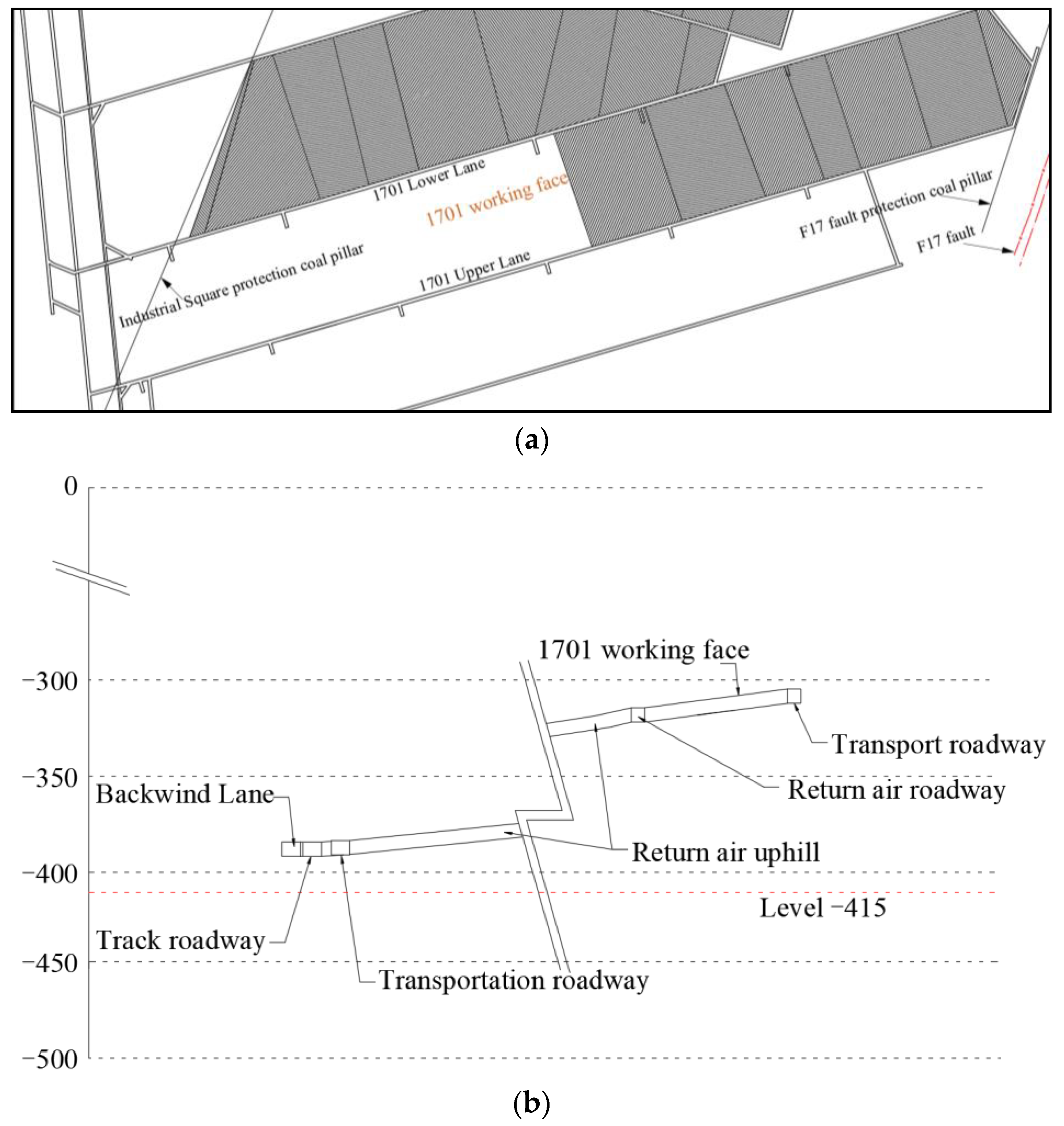
The F17 fault protection coal pillar, the industrial square protection coal pillar, and the 1701 east upper working face are all accessible from the 1701 working face, which is situated at level −415 to the east of the initial mining area. Figure 1 depicts its location. The mining coal seam is the 7th coal seam, and the working face is vertically 360.18 to 388.50 m above the earth. The ground elevation of the working face is 29.7 to 30.9 m. With a coal seam strike of 50 to 75 degrees and a dip to the north, this face has a wide and mild monoclinic structural character. The coal seam has a comparatively low dip angle of three to five degrees. The coal seam has a thickness that varies from 1.05 to 1.20 m, with an average coal thickness of 1.15 m and a generally consistent thickness variation.
2.2. Rock Character Analysis of Coal Seam Roof and Floor
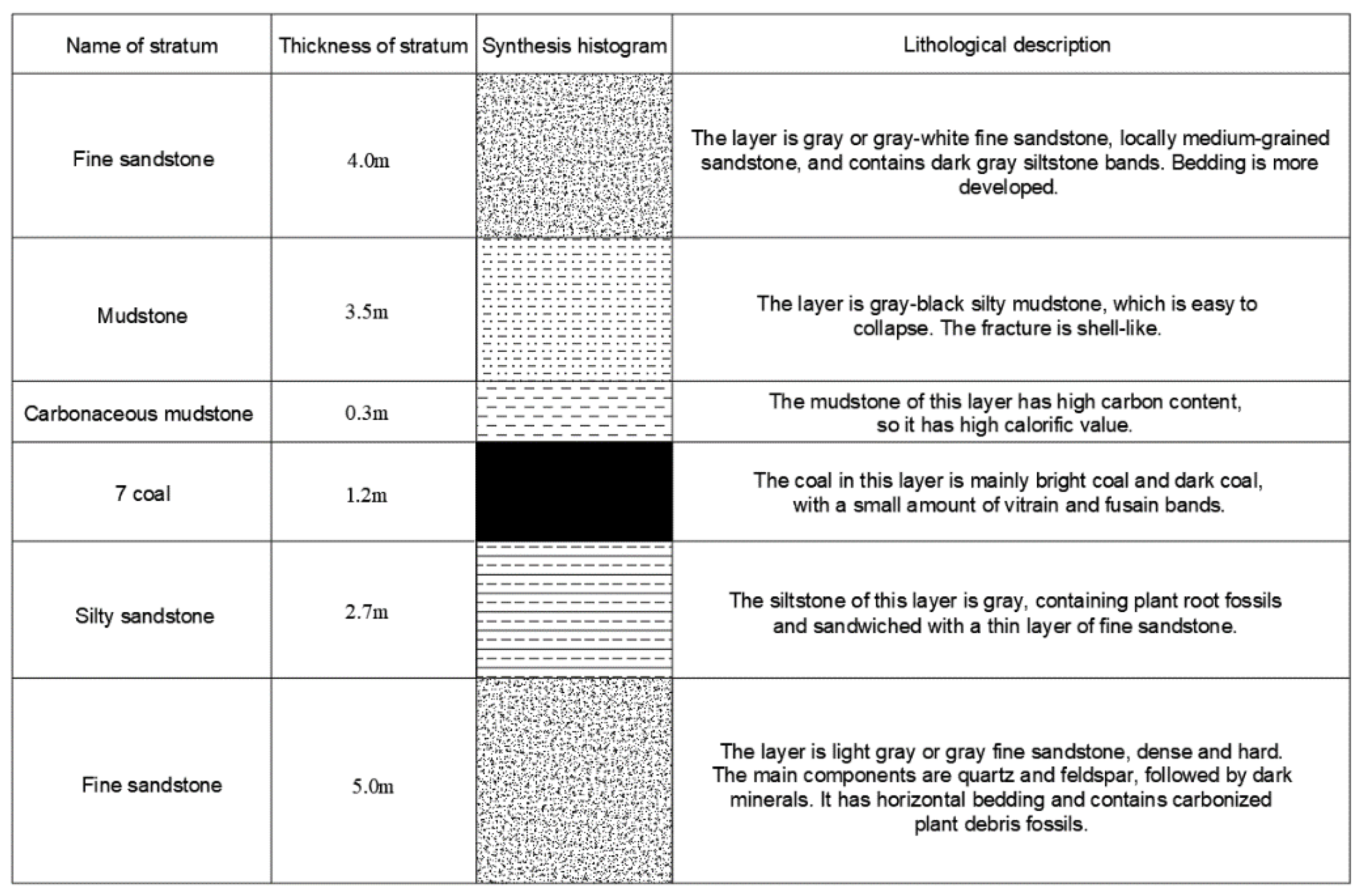
Working Face 1701′s immediate floor of roadway is made of a dark grey siltstone that is 1.0–1.2 m thick and contains fossilized plant roots. Its lower portion is sandwiched by narrow bands of fine sandstone that are rich in fossilized plant detritus and pyrite films. Light grey fine sandstone with a thickness of about 5.0 m forms the fundamental bottom. It is dense and hard, primarily made of quartz and feldspar, and is followed by dark minerals with horizontal bedding that contains fossilized carbonized plant waste. Figure 2 depicts the rock characteristics of the coal seam roof and floor.
Plant debris fossils are present in the rock stratum beneath the road, and they expand when they come into contact with water. However, because of the straightforward hydrogeological circumstances, the floor aquifer’s water quantity is weak and its influence on floor heave is minimal.
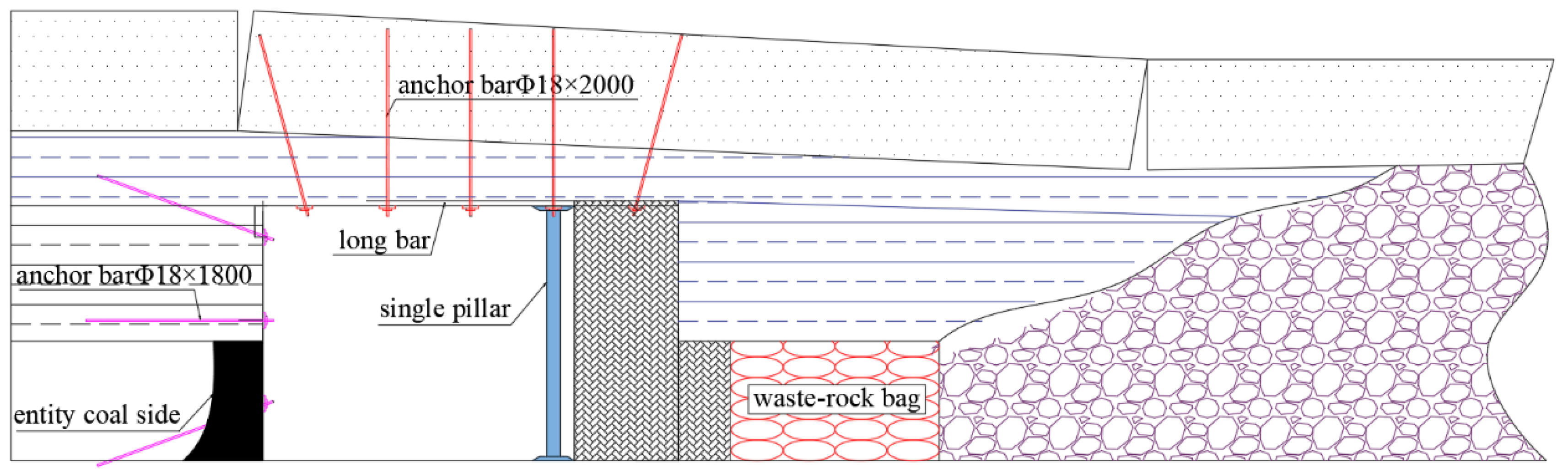
2.3. Supporting Scheme for Gob-Side Entry Retaining
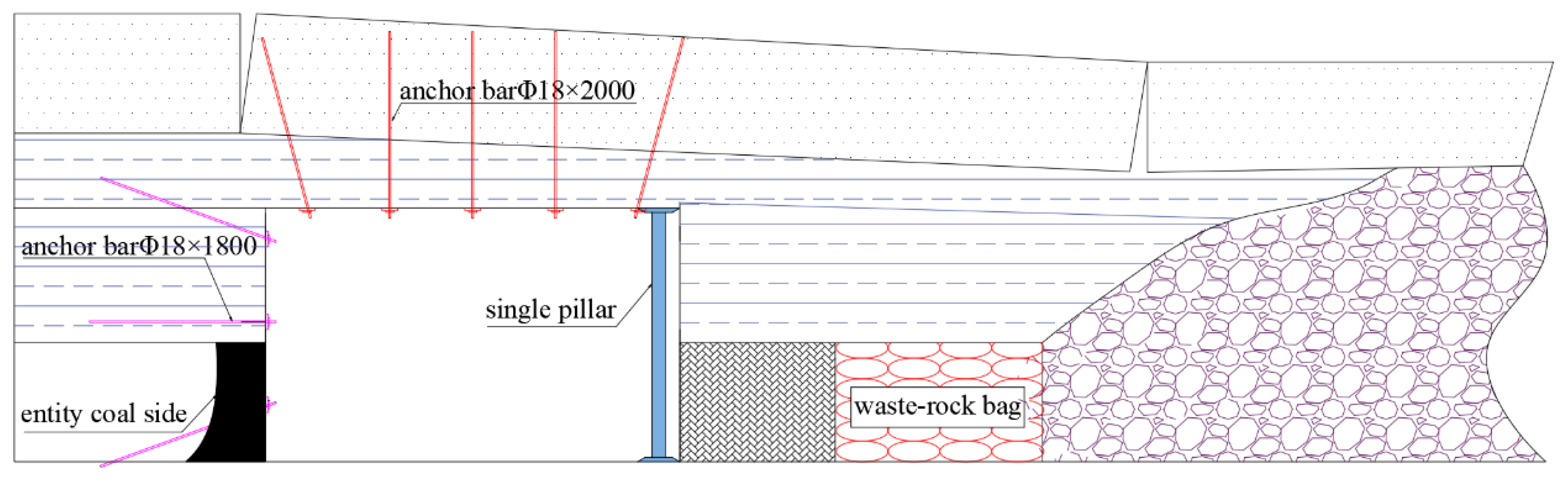
The “anchor net-steel belt” support type is used in the 1701 upper roadway support design. The width of the roadway is 4 m and the height is 2.5 m. The roof bolt parameters are Φ 18 × 2000 mm equivalent strength full thread steel with a spacing of 800 × 800 mm on the roof. The roadside bolt parameters are Φ 18 × 1800 mm equivalent strength full thread steel with a spacing of 800 × 900 mm on the coal wall. Anchor mesh is laid across the whole tunnel portion. The highway for insitu retaining is used for the gob-side entry retaining. The paste-based filler body has dimensions of 1.5 m in width and 1.15 m in height, and it is attached to the coal seam roof. A single pillar supports the roof on the side of the paste-based filler body. On the goaf side, a 2.0mwide gangue wall is manually constructed. Figure 3 depicts the precise layout diagram.
2.4. Characteristics of Floor Heave
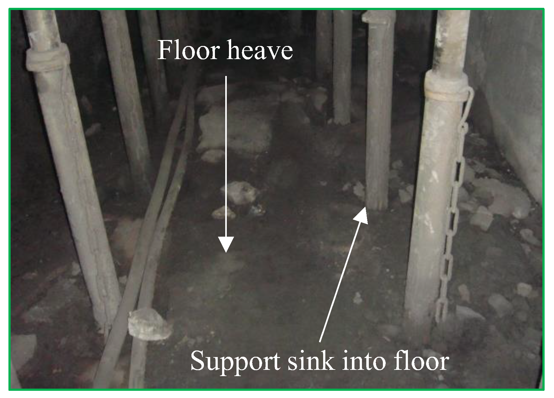
Observations made on the ground revealed that while the upper roadway roof support is dense and sturdy, the floor is unsupported. The road exhibited floor heave after gob-side entry had been retained for some time. The roadside support bodies have tilted and shear failure has occurred close to the roof and floor of the roadway. The deformation of the coal side roadway is relatively small, and there is no damage phenomenon. The roof has minimal damage and is relatively complete. The height of local floor heave is about 1 m, seriously affecting the normal use of the roadway. Figure 4 depicts the deformation and failure of the tunnel floor heave.
3. Mechanical Model of Floor Heave in Gob-Side Entry Retaining
3.1. Analysis on the Mechanism of Floor Heave in Gob-Side Entry Retaining
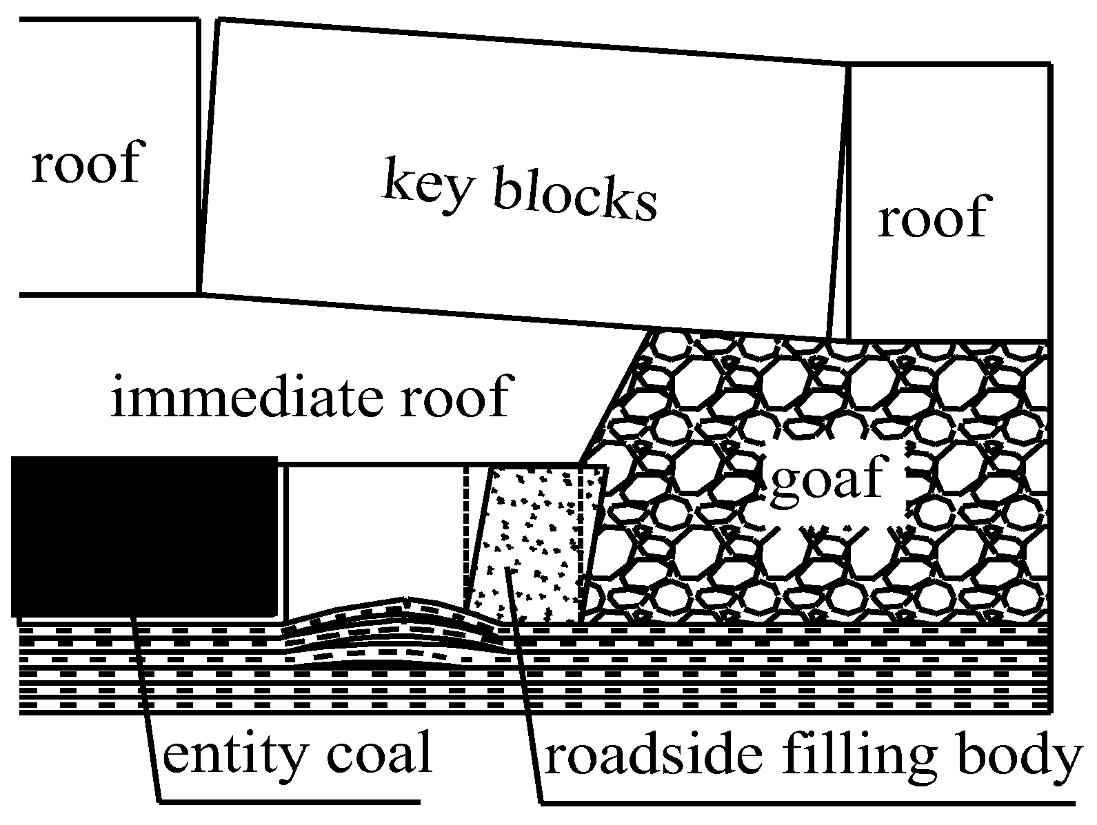
It can be deduced from the theory of key layers and the law of overlying rock movement along gob-side entry retaining roadway that after the working face is pushed, the key roof breaks near goaf to form a masonry beam structure, the lateral concentrated stress shifts towards the solid coal side, causing a secondary distribution of surrounding rock stress and the occurrence of concentrated stress (Figure 5 [35,36]).
The load carried by the filling body and coal increases quickly as the key blocks rotate and sink, causing a large stress concentration at the base corner of the road and the likelihood of both ends of the floor rock layer being damaged. The base angle practically loses its ability to support vertical loads when it is damaged. Because of this, as the two sides of the roadway move relatively close together, the weaker floor layer experiences compression deformation due to the compression of the filling body and solid coal next to the roadway as well as the floor’s stress, which finally causes the floor to raise and form a floor heave.
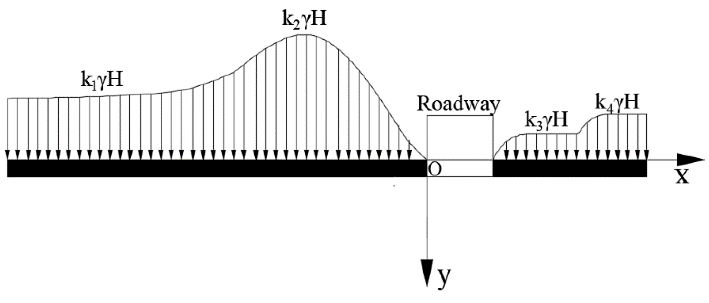
3.2. Stress Analysis of Gob-Side Entry Retaining
A stress study of the floor of the gob-side entry retaining roadway can be established based on the analysis mentioned above, as shown in Figure 6. The working face’s advanced support pressure is shown as k1, the high support pressure zone’s stress concentration coefficient is shown as k2, the filling body next to the roadway’s stress concentration coefficient is shown as k3, the stress concentration coefficient after compaction of goaf is shown as k4, γ reflects the average rock layer’s weight in units (N/m3), and h reflects the depth of the mine.
The theoretical method of elastic foundation beams is adopted in this paper. The elastic foundation beam model is widely used to solve the deformation problems of the roof and floor of working faces. The mechanical model has the following assumptions: (1) The foundation is simplified as an elastic body. (2) The settlement at any point on the foundation is directly proportional to the pressure on that unit. (3) The floor is assumed to be a beam, and the deformation conforms to the solution assumption of the beam. (4) The deformation of the floor is continuous.
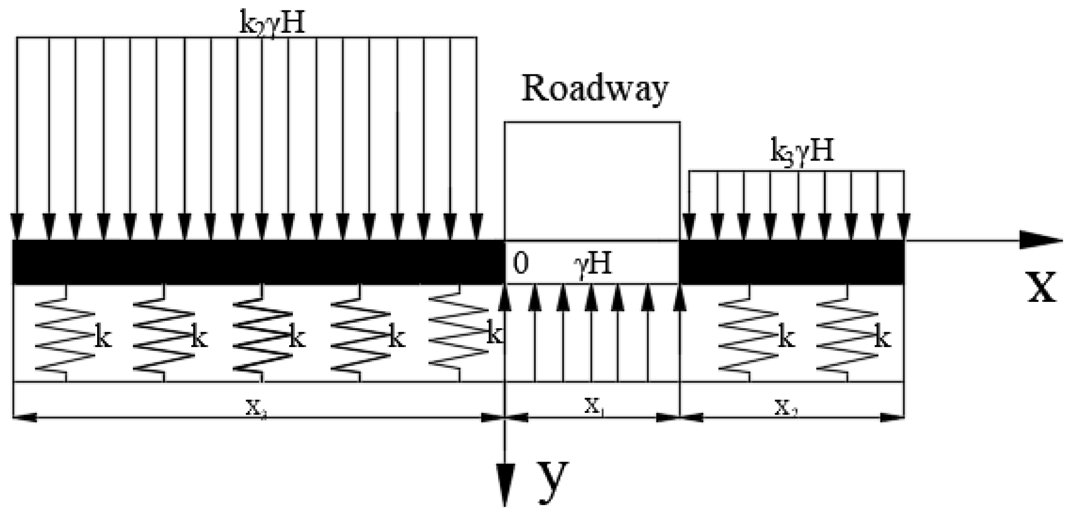
The high support pressure area formed by the superposition of lateral support pressure and advanced support pressure on the left side of the roadway and the stress concentration area of the filling body next to the roadway on the right side are simplified as uniformly distributed loads in order to simplify the study of the mechanical behavior of the floor heave of the goaf retaining roadway without losing its essence. As an elastic foundation, the fundamental floor’s force on the nearby floor is distilled. In Figure 7, the model is displayed.
The Winkle assumption of an elastic foundation states that any point’s settlement on its surface is directly proportionate to the pressure applied to that location per unit area [37,38,39], i.e.,
The pressure per unit area is denoted by q in the formula.; represents the foundation’s bending; k shows the foundation coefficient, which is described as,
E and H in the formula stand for the rock layer’s elastic modulus and thickness, respectively.
The basic differential equation of the foundation beam deflection curve should be satisfied by the relationship between the deflection of the roof and the load on the roof rock beam, according to the theory of elastic foundation rock beams:
The differential equation for the roof rock beam’s deflection curve is as follows:
Create Equation (4):
The homogeneous equation of Equation (7) is:
The general solution of homogeneous Equation (8) is:
In the equation, .
Since a specific answer to the nonhomogeneous Equation (7) is: , the nonhomogeneous Equation (7) has the following generic solution:
For the analysis of Equation (10), when , the roof subsidence is a certain value , only if . Therefore, the answer to problem (10) can be written as follows:
Similarly, when , the differential equation describing the roof deflection curve in the roadway roof control region has the following general solution:
In the equation, .
When , in the roadway roof control area, the differential equation describing the roof deflection curve has the following general solution:
In conclusion, the differential equation for the roof beam’s deflection curve is:
The rotation angle, bending moment, and sheer force of any section can be calculated using the following equations once the beam’s deflection curve has been determined:
Taking into account the boundary deflection value and the deflection curve equation’s continuity condition:
The parameters A1, A2, B1, B2, B3, B4, C1 and C2 can be solved. The parameter form is not supplied here since it is too complicated. By adding the solved parameters to Formula (14), it is possible to construct the deflection curve equation for the roof rock beam.
4. Engineering Calculation Example
4.1. Determination of Calculation Parameters
The following parameters are chosen based on the field geological characteristics of the 1701 upper roadway employing roadside paste filling gob-side entry retaining technology:
The working face’s immediate floor thickness is 1.2 m, fundamental floor thickness H1 = 3.7 m, the coal seam is situated at a depth of 400 m, and q0 = 10 MPa. According to the outcomes of the laboratory tests, the immediate floor’s and the fundamental floor rock’s elastic modulus are E1 = 0.5 GPa, E2 = 15 GPa; the solid coal side’s stress concentration factor, k2, is 2~2.5, take k2 = 2.5, and the paste filling body’s k3 stress concentration factor is 0.25~0.45. The goaf compaction region is chosen as the calculation range due to the short length of the paste filling body 10 m, take k3 = 0.8.
4.2. Analysis of Calculation Results
The pertinent parameters are introduced into the mechanical model illustrated in Figure 7, and using the solution condition (16), the floor deflection curve equation for gob-side entry retention may be produced. The primary parameters are provided in Table 1 due to the equation’s complexity, and they are then added to Equation (14) to produce the floor deflection curve equation , and .
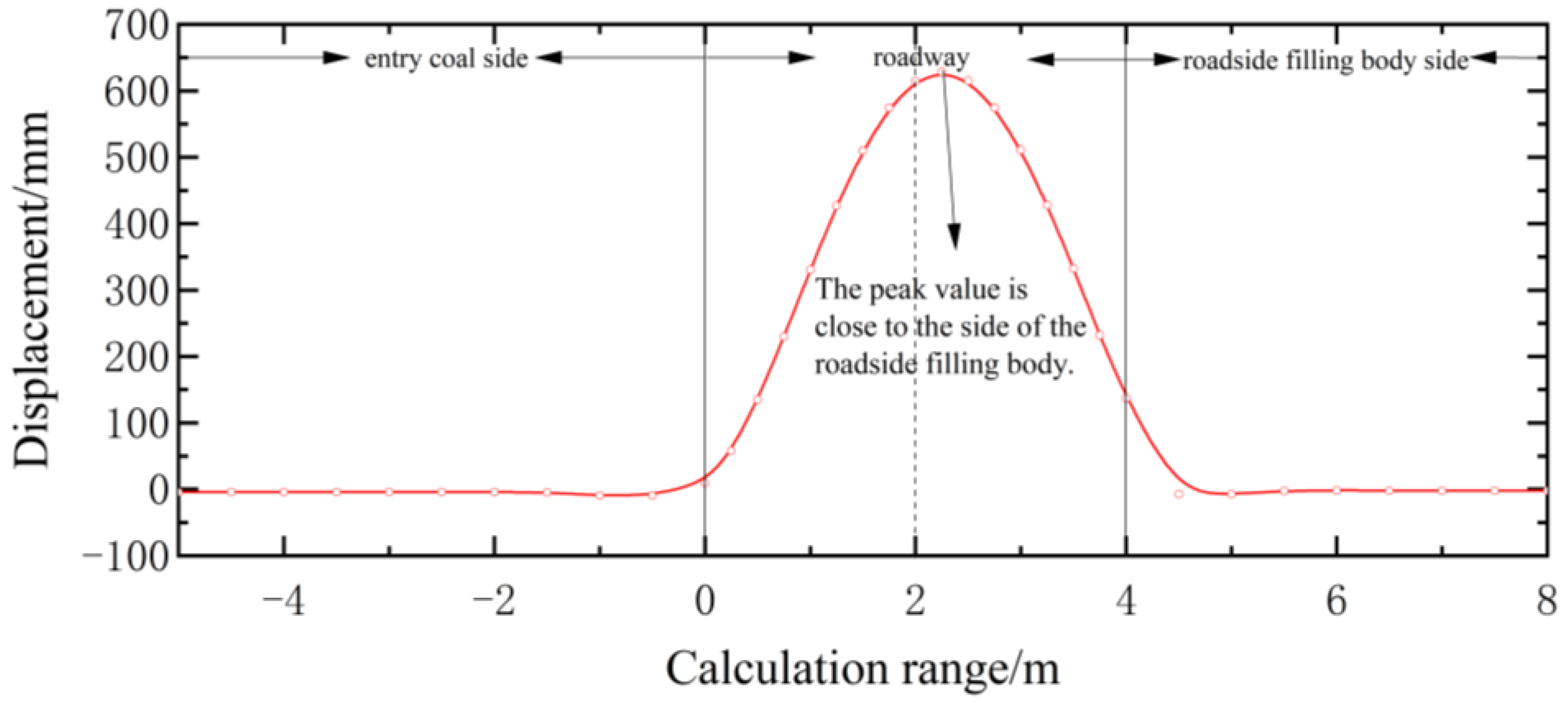
Deflection curve equations , and using software Origin 8.0, displays Figure 8 as the displacement curve of the floor of the gob-side entry retaining with paste filling.
Figure 8 shows that the floor deformation on the side of solid coal and the body supporting the roadside is almost nil, whereas the floor deformation of the roadway area is characterized by a “parabola,” with a nonsymmetrical phenomenon. The deformations of the fill body side and the entity coal side near the roadway are 137 mm and 9.7 mm, respectively. Analysis of the reasons shows that the solid coal side has not been excavated, and the floor is compacted by the solid coal and the overlying rock layer, resulting in relatively small deformation of the floor heave. On the side of the filling body, due to the excavation of the coal seam, the paste-based filler body and gangue wall are filled, and the roof is still affected by mining stress, with a certain amount of floor heave deformation. With a maximum value of 628 mm, the floor heave distortion is greatest next to the side of the roadside support body. Analyzing the causes reveals that the working face mining has a greater impact on the deformation of the roadway floor heave close to the goaf side.
4.3. Model Validation
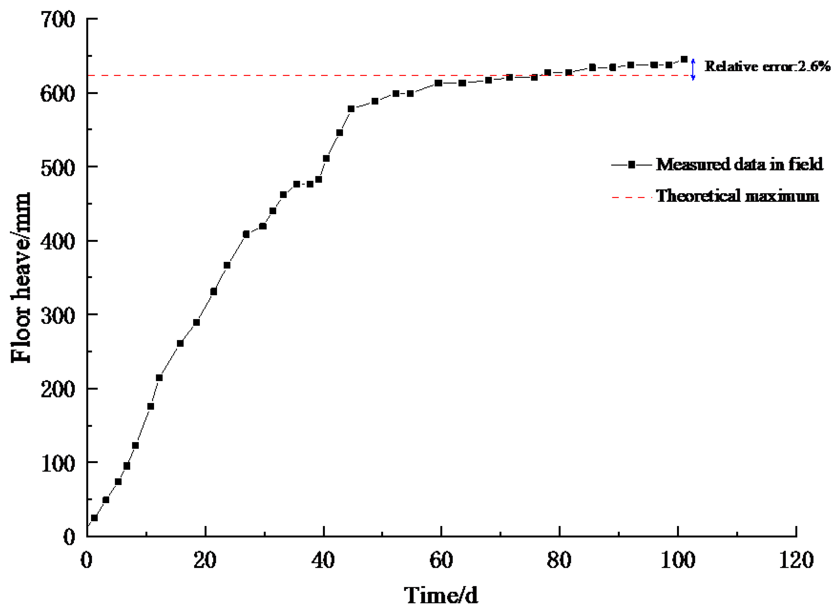
The deformation monitoring points are arranged by the cross-point placement method [40]. The center line and waist line are respectively set in the middle of the roadway roof and the middle of the roadway height on both sides to measure the deformation. The floor of the gob-side entry retaining’s 100 days deformation curve is depicted in Figure 9 as a result of the observation of the floor deformation of the 1701 upper highway.
Figure 9 shows that the floor deformation of 1701 upper roadway gets worse over time. After 50 days, the roadway floor heave deformation rate slows to 0.9 mm/d; after 100 days, the maximum deformation is 645 mm, and the difference between the theoretical model maximum and the measured maximum is 2.6%. In the first 50 days, the roadway floor heave deformation rate is fast, reaching 13.3 mm/d.
5. Discussion
5.1. The Influence of Seam Depth on Floor Heave
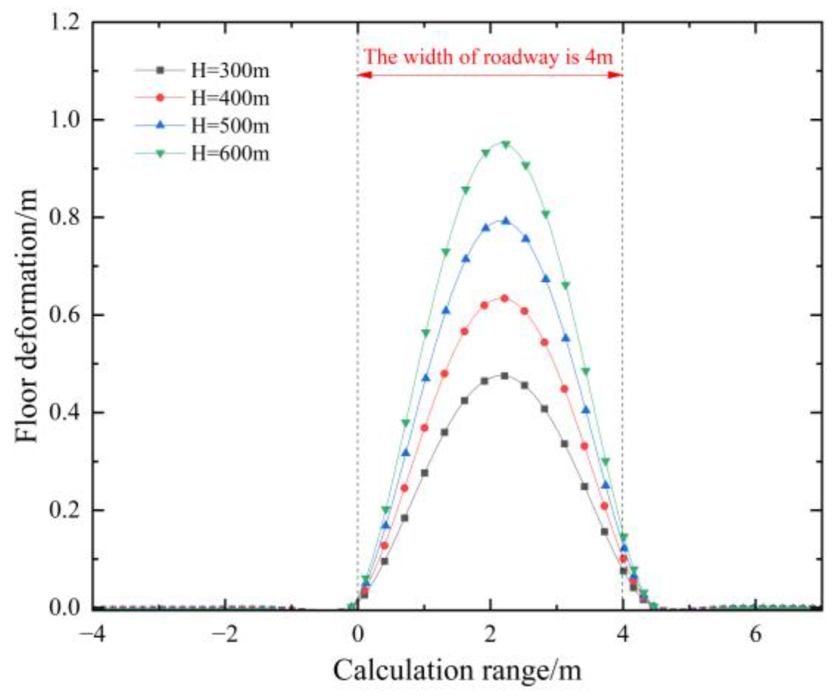
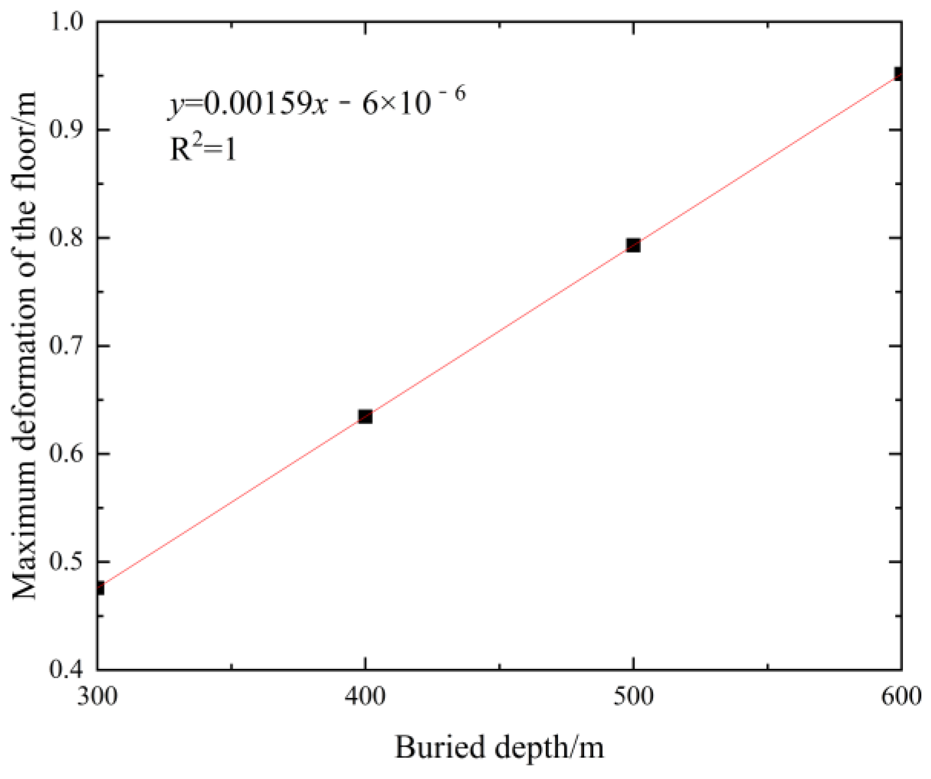
The maximum error between the theoretical model and the measured maximum value is 2.6%, which confirms the theoretical reliability of the floor heave mechanical model of the gob-side entry retaining based on a comparative analysis of the measured data of the floor deformation of the 1701 upper roadway and the theoretical calculation results of the floor heave mechanical model of the gob-side entry retaining. The floor heave law of gob-side entry retaining is theoretically examined using the floor heave mechanical model of gob-side entry retaining at various buried depths. There will be four different burial depths: 300, 400, 500, and 600 m. Figure 10 depicts the displacement curve of the floor of the paste-filled gob-side entry retaining at the equivalent buried depth. The relationship between maximum of gob-side entry retaining floor deformation and buried depth is shown in Figure 11.
As demonstrated in Figure 10, the maximum deformation of the roadway floor increases as the buried depth increases, as does ground stress. The maximum deformation of the floor is 0.49 mm, 0.65 mm, 0.8 mm, and 0.96 mm when H is 300, 400, 500, and 600 m, respectively; the maximum deformation of the floor grows linearly with the increase in buried depth. The maximum floor heave of the roadway floor rises by around 0.15 mm for every 100 m increase in buried depth. The formula of deformation of the roadway floor and buried depth is y = 0.0159x − 6 × 10⁻⁶, and there is a linear relationship between the two.
5.2. The Influence of Roadway Width on Floor Heave
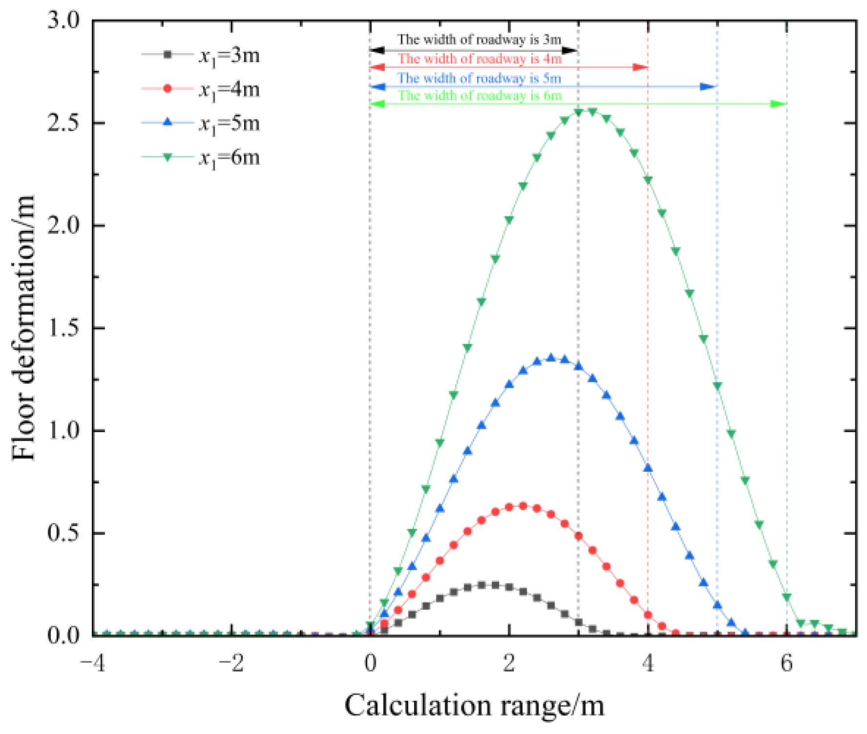
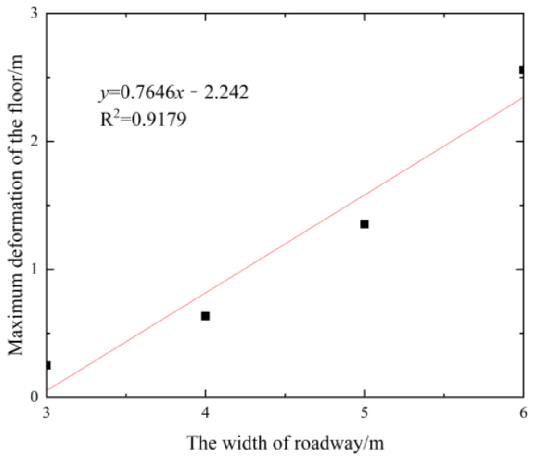
The degree of floor deformation and collapse is significantly influenced by the width of the gob-side entry retaining highway. Four types of widths are specified to be 3 m, 4 m, 5 m, and 6 m, respectively, with other parameters remaining the same, using the 400 m buried depth as an example. In Figure 12, it is possible to derive the displacement curve of the floor of the gob-side entry holding with paste filling beneath the equivalent roadway width. The relationship between maximum of gob-side entry retaining floor deformation and the roadway width is shown in Figure 13.
The deformation of the floor of the roadway area is characterized by a “parabola,” which has a nonsymmetrical phenomenon, as can be seen in Figure 11. The deformation of the floor on the side of solid coal and roadside filling body is close to zero. The side of the roadside filling body is where the floor heave’s maximum deformation is found. As the width of the road rises, the asymmetric failure of the highway floor becomes more apparent, and the maximum deformation increases nonlinearly. When the width of the road is 3 m, 4 m, 5 m, and 6 m, the greatest highway floor displacement occurs at 0.25 m, 0.63 m, 1.35 m, and 2.55 m. Therefore, it can appropriately reduce the width of the roadway to reduce the amount of floor heave. It is also possible to reduce the floor heave by moving the paste-based filler body to inside of the roadway and reducing the width of it. The formula of deformation of the roadway floor and the roadway width is y = 0.7646x − 2.242, and the correlation coefficient is 0.9179, indicating a strong correlation between the two.
5.3. The Influence of Elastic Modulus of Immediate Floor on Floor Heave
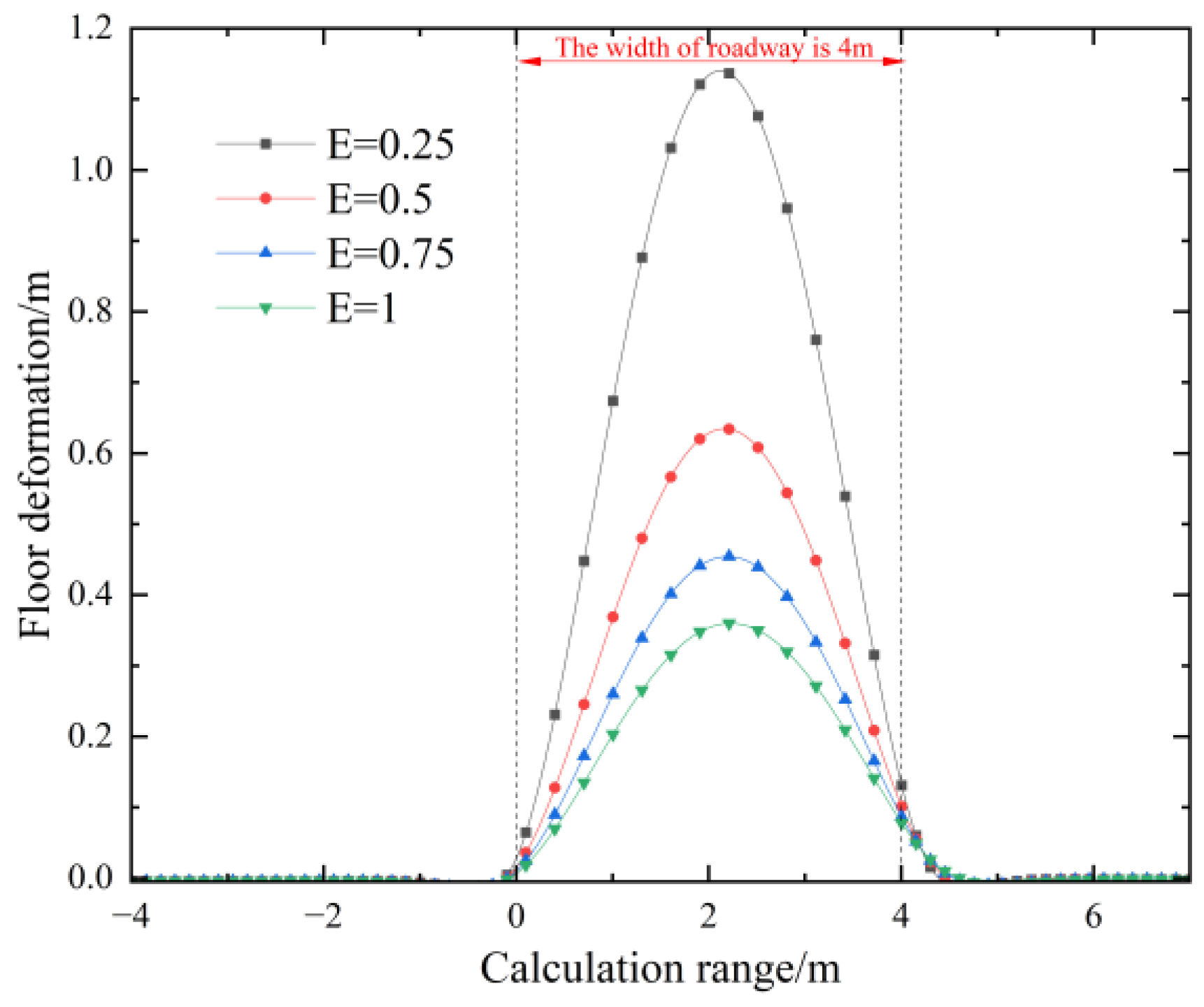
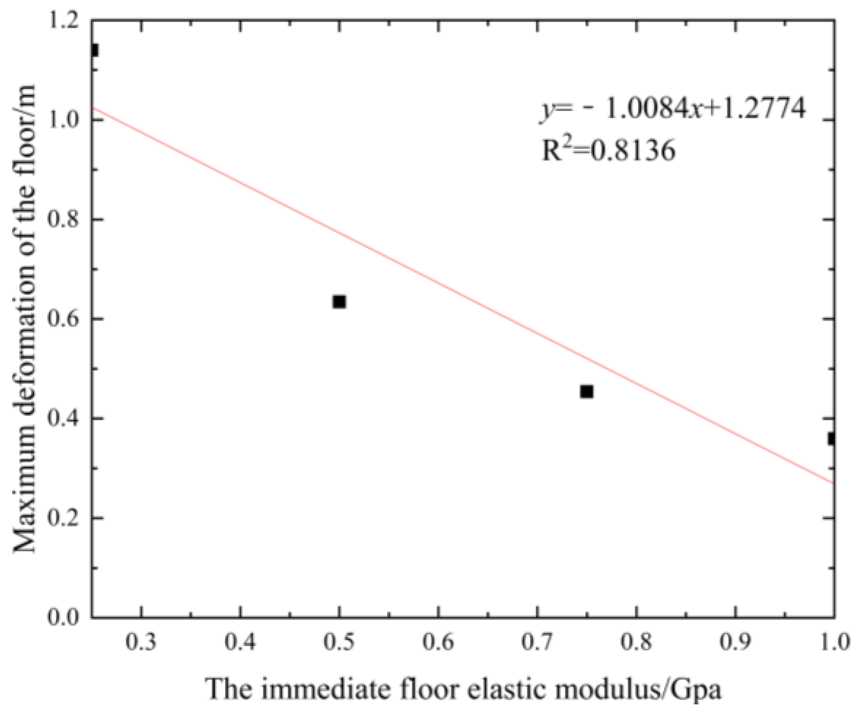
Four different types of floor elastic modulus are built with values of 0.25, 0.5, 0.75, and 1, respectively, using the 400 m buried depth as an example. In Figure 14, the displacement curve of the floor of the gob-side entry holding with paste filling is depicted under the assumption that the floor elastic modulus is the same. The relationship between maximum of gob-side entry retaining floor deformation and the immediate floor elastic modulus is shown in Figure 15.
Elastic modulus is a metric used to gauge how difficult it is to deform elastic material. Figure 12 illustrates how the deformation of floor heave reduces as the elastic modulus of the roadway floor rises. The maximum deformation falls nonlinearly as the roadway’s elastic modulus rises. When the roadway floor’s elastic modulus is 0.25, 0.5, 0.75, and 1, the greatest highway floor displacement occurs at 1.14 m, 0.63 m, 0.45 m, and 0.36 m. Therefore, by hardening the roof of the roadway, thereby increasing the strength and deformation resistance of the roadway floor, the roadway floor heave can be reduced. The formula of deformation of the roadway floor and the immediate floor elastic modulus is y = −1.0084x + 1.2774.
5.4. Guidance for On Site Application
The above study of the mechanism of floor heave in goaf roadways changes the design of tunnels, controls the floor heave of the roadway, and meets the requirements of mine production. Without changing other parameters, only changing the method of roadside support can also reduce the floor heave of the roadway. By increasing the volume of the paste filling body beside the roadway and moving the filling body to the middle of the roadway, the width of the roadway can be reduced, thereby reducing the floor heave of the roadway. The specific arrangement is shown in Figure 16.
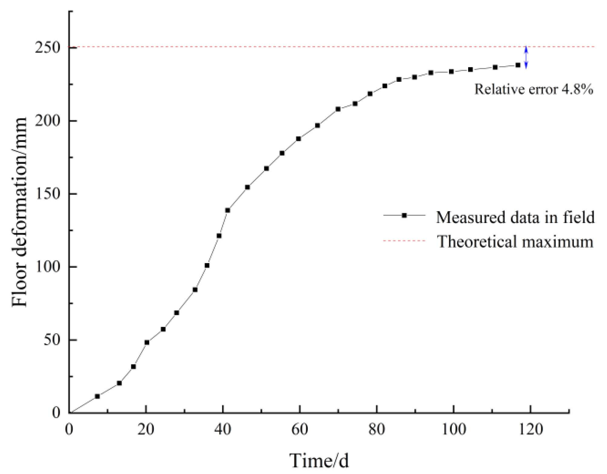
The optimization scheme has been applied in practice. The optimized deformation curve of the floor heave of the gob-side entry retaining is shown in Figure 17.
Figure 17 shows that the measured maximum deformation of the floor heave is 238 mm, with an error of 4.8% from the theoretical maximum value. This indicates that the improvement of roadway support has a significant effect on reducing the deformation of the floor heave, and also proves the correctness of the theory.
6. Conclusions
Winker elastic foundation is used to create the mechanical model of floor heave in gob-side entry retention, and the analytical solution to the floor heave deformation deflection equation is provided. The mechanism of the floor heave deformation of the goaf retaining roadway in a thin coal seam is explained. The influence of different factors on the deformation of the floor heave of the goaf retaining roadway was analyzed. An innovative proposal to move the paste-based filler body into the interior of the roadway to reduce floor deformation was provided. The paper has important guiding significance for explaining the mechanism of floor heave in goaf roadway and controlling the deformation of the roadway floor. The conclusions are as follows.
(1) The results of the theoretical calculations reveal that the deformation of the floor on the side of the solid coal and roadside support body is almost nil, and that the deformation of the floor in the roadway area is characterized by a “parabola” and nonsymmetrical phenomenon. The floor heave deformation reaches a maximum value of 628 mm close to the side of the roadside support body.
(2) With passing time, the floor of 1701 Upper Roadway becomes more deformed. The rate of roadway floor heave deformation is faster in the first 50 days, reaching 13.3 mm/d; after 50 days, the rate is relatively mild, reaching 0.9 mm/d; the maximum deformation is 645 mm after 100 days, and the difference between the maximum value predicted by the theoretical model and the maximum value actually measured is 2.6%.
(3) Roadside filling bodies and the bottom of solid coal-sided walls deform very little. “Parabola”, with non-positive symmetry, characterizes the deformation of the floor in the roadway area. The side of the roadside filling body is where the floor heave deforms the most. The buried depth, highway width, and the floor’s elastic modulus are all linearly and positively connected with the floor heave value and asymmetry, respectively.
Author Contributions
Conceptualization, P.H. and M.L.; methodology, J.X.; software, G.R.; validation, C.Z. and F.C.S.; formal analysis, P.H.; investigation, M.L.; resources, G.R.; data curation, C.Z.; writing—original draft preparation, P.H.; writing—review and editing, P.H. and J.X.; visualization, C.Z.; supervision, J.X.; project administration, M.L.; funding acquisition, P.H. All authors have read and agreed to the published version of the manuscript.
Funding
This research was funded by the National Natural Science Foundation of China (52104105) and the Key Laboratory of Deep Earth Science and Engineering (Sichuan University), Ministry of Education (DESE202203).
Institutional Review Board Statement
Not applicable.
Informed Consent Statement
Not applicable.
Data Availability Statement
The data presented in this study are available on request from the corresponding author.
Conflicts of Interest
The authors declare that they have no conflict of interest to this work.
References
- Tan, Y.L.; Yu, F.H.; Ning, J.G.; Zhao, T.B. Design and construction of entry retaining wall along a gob side under hard roof stratum. Int. J. Rock Mech. Min. Sci. 2015, 77, 115–121. [Google Scholar] [CrossRef]
- Jiang, Y.; Zhao, Y.; Liu, W.; Li, Q. Research on the problem of Roadway Floor Heave in Deep Mining. Chin. J. Rock Mech. Eng. 2004, 14, 2396–2401. [Google Scholar]
- Zhang, Z.; Deng, M.; Bai, J.; Yan, S.; Yu, X. Stability control of gob-side entry retained under the gob with close distance coal seams. Int. J. Min. Sci. Technol. 2020, 31, 321–332. [Google Scholar] [CrossRef]
- Tian, Z.; Zhang, Z.; Deng, M.; Yan, S.; Bai, J. Gob-Side Entry Retained with Soft Roof, Floor, and Seam in Thin Coal Seams: A Case Study. Sustainability 2020, 12, 1197. [Google Scholar] [CrossRef] [Green Version]
- Gao, H.; Gao, Y.; Wang, J.; Fu, Q.; Qiao, B.; Wei, X.; Zhang, X. Study on Bidirectional Blasting Technology for Composite Sandstone Roof in Gob-Side Entry-Retaining Mining Method. Appl. Sci. 2021, 11, 7524. [Google Scholar] [CrossRef]
- Wang, W.; Hou, C. Analysis of the relationship between abutment pressure and floor heave of mining roadway. J. Min. Saf. Eng. 2002, 66–67, 70. [Google Scholar]
- Liu, C.; Song, S.M.; Liu, X.; Zhang, X.L.; Luo, W. Study on the mechanical principle of floor heave in mining roadway. J. Min. Saf. Eng. 2003, 20, 24–27. [Google Scholar]
- Zhang, H.; Han, L.; He, Y.; Shao, P.; Jiang, B. Study on floor heave control of swelling soft rock roadway in complex structural area. J. Min. Saf. Eng. 2011, 028, 16–21,27. [Google Scholar]
- Liu, S.; Zhang, W.; Feng, Y. Migration mechanism and control measures of sliding floor heave rock mass in deep coal roadway. J. Min. Saf. Eng. 2013, 3005, 706–711. [Google Scholar]
- Yang, H.; Cao, S.; Wang, S.; Fan, Y.; Wang, S.; Chen, X. Adaptation assessment of gob-side entry retaining based on geological factors. Eng. Geol. 2016, 209, 143–151. [Google Scholar] [CrossRef]
- Zhang, N.; Yuan, L.; Han, C.; Xue, J.; Kan, J. Stability and deformation of surrounding rock in pillarless gob-side entry retaining. Saf. Sci. 2012, 50, 593–599. [Google Scholar] [CrossRef]
- Zheng, W.; Duan, H. Discussion on stability analysis and support technology of surrounding rock of gob-side entry retaining. J. Vibroeng. 2019, 21, 1058–1068. [Google Scholar] [CrossRef]
- Zhao, B.; He, S.; He, X.; Gao, L.; Li, Z.; Song, D.; Shen, F. Research on Deformation and Failure Control Technology of a Gob-Side Roadway in Close Extra-Thick Coal Seams. Sustainability 2022, 14, 11246. [Google Scholar] [CrossRef]
- Li, Z.; Zhang, Y.; Ma, Q.; Zheng, Y.; Song, G.; Yan, W.; Zhang, Y.; Hu, L. The Floor Heave Mechanism and Control Technology of Gob-Side Entry Retaining of Soft Rock Floor. Sustainability 2023, 15, 6074. [Google Scholar] [CrossRef]
- Zhou, X.; Wang, S.; Li, X.; Meng, J.; Li, Z.; Zhang, L.; Pu, D.; Wang, L. Research on Theory and Technology of Floor Heave Control in Semicoal Rock Roadway: Taking Longhu Coal Mine in Qitaihe Mining Area as an Example. Lithosphere 2022, 2022, 3810988. [Google Scholar] [CrossRef]
- Ma, Z.; Guo, Z.; Wang, H.; Hu, J.; Li, T.; Chen, J. Large Deformation Mechanism and Three-Level Control Technology of Entry Retaining in Three-Soft Thick Coal Seams. Geotech. Geol. Eng. 2020, 38, 6125–6143. [Google Scholar] [CrossRef]
- Bai, J.; Li, W.; Wang, X.; Xu, Y.; Huo, L. Mechanism and control technology of floor heave in mining roadway. J. Min. Saf. Eng. 2011, 28, 1–5. [Google Scholar]
- Shi, J.; Kong, D. Floor Heave Mechanism and Anti-Slide Piles Control Technology in Deep and Large-Span Chamber. Appl. Sci. 2021, 11, 4576. [Google Scholar] [CrossRef]
- Haramy, K.; Mcdonnell, J. Floor Heave Analysis in a Deep Coal Mine; American Rock Mechanics Association: Alexandria, VA, USA, 1986. [Google Scholar]
- Perry, K.; Bradley, J.; Unrug, K.; Klimek, M. Mitigation of floor heave in West Kentucky Coal Mine. Int. J. Min. Sci. Technol. 2016, 26, 521–525. [Google Scholar] [CrossRef]
- Mo, S.; Tutuk, K.; Saydam, S. Management of floor heave at Bulga Underground Operations—A case study. Int. J. Min. Sci. Technol. 2018, 29, 73–78. [Google Scholar] [CrossRef]
- Shreedharan, S.; Kulatilake, P.H. Discontinuum-Equivalent Continuum Analysis of the Stability of Tunnels in a Deep Coal Mine Using the Distinct Element Method. Rock Mech. Rock Eng. 2016, 49, 1903–1922. [Google Scholar] [CrossRef]
- Park, D.-W.; Ash, N.F. Stability analysis of entries in a deep coal mine using finite element method. Min. Sci. Technol. 1985, 3, 11–20. [Google Scholar] [CrossRef]
- An, Z.; Zhang, N.; Ni, J.; Xu, X. Floor Heave Control Technology of Soft and Broken Rock Roadway in Zhuxianzhuang Coal Mine. J. Min. Saf. Eng. 2008, 03, 263–267. [Google Scholar]
- Kang, H.; Lu, S. Analysis of floor heave mechanism of roadway. J. Rock Mech. Eng. 1991, 10, 362. [Google Scholar]
- Hua, X.; Lu, X.; Li, Y. Floor heave prevention and control technology of large section gob-side entry retaining in deep mine. Coal Sci. Technol. 2013, 41, 100–104. [Google Scholar]
- Xu, Y.; Zhou, H.; Bai, J.; Chen, J. Study on floor heave characteristics and control methods of gob-side entry retaining. J. Rock Mech. Eng. 2015, S2, 4235–4243. [Google Scholar]
- Sakhno, I.; Liashok, I.; Svitlana, S.; Oleksandr, I. Method for controlling the floor heave in mine roadways of underground coal mines. Min. Mineral Deposits 2022, 16, 1–10. [Google Scholar] [CrossRef]
- Ilinets, A.A.; Sidorenko, A.A.; Sirenko, Y.G. Computer modelling of a floor heave in coal mines. J. Phys. Conf. Ser. 2019, 1333, 032028. [Google Scholar] [CrossRef]
- Małkowski, P.; Ostrowski, Ł.; Stasica, J. Modeling of Floor Heave in Underground Roadways in Dry and Waterlogged Conditions. Energies 2022, 15, 4340. [Google Scholar] [CrossRef]
- Khalymendyk, I.; Baryshnikov, A. The mechanism of roadway deformation in conditions of laminated rocks. J. Sustain. Min. 2018, 17, 41–47. [Google Scholar] [CrossRef]
- Sakhno, I.; Sakhno, S. Numerical studies of floor heave mechanism and the effectiveness of grouting reinforcement of roadway in soft rock containing the mine water. Int. J. Rock Mech. Min. Sci. 2023, 170, 105484. [Google Scholar] [CrossRef]
- Mo, S.; Ramandi, H.L.; Oh, J.; Masoumi, H.; Canbulat, I.; Hebblewhite, B.; Saydam, S. A new coal mine floor rating system and its application to assess the potential of floor heave. Int. J. Rock Mech. Min. Sci. 2020, 128, 104241. [Google Scholar] [CrossRef]
- Shimada, H.; Hamanaka, A.; Sasaoka, T.; Matsui, K. Behaviour of grouting material used for floor reinforcement in underground mines. Int. J. Min. Reclam. Environ. 2013, 28, 133–148. [Google Scholar] [CrossRef]
- Miu, X.; Qian, M. Mechanical model of the whole structure of surrounding rock and masonry beam. J. Min. Saf. Eng. 1995, Z1, 3–12+197. [Google Scholar]
- Li, C.; Zhang, Y.; Zuo, J.; Tang, S.; Liu, S. Mechanical behavior and zoning characteristics of floor failure caused by instability disturbance of masonry beam in deep mining. Coal J. 2019, 44, 1508–1520. [Google Scholar]
- Huang, M.-H.; Thambiratnam, D.P. Dynamic Response of Plates on Elastic Foundation to Moving Loads. J. Eng. Mech. 2002, 128, 1016–1022. [Google Scholar] [CrossRef]
- Deng, X.; Zhang, J.; Huang, P.; Zhang, Q.; Hao, X. Analysis of roof movement characteristics of upward layered filling mining in extra-thick coal seam. J. Coal 2015, 40, 994–1000. [Google Scholar]
- Avramidis, I.; Morfidis, K. Bending of beams on three-parameter elastic foundation. Int. J. Solids Struct. 2006, 43, 357–375. [Google Scholar] [CrossRef] [Green Version]
- Gui, B.; Guo, J.; Chen, B. Experimental Study on the Distribution Characteristics of Advance Support Pressure in the 163 Lower 02 Working Face of Jisan Coal Mine. Coal Sci. Technol. 2007, 5, 66–68. [Google Scholar]
Figure 1.
Diagram showing (a) working face layout and (b) level −415.

Figure 2.
Coal seam roof and floor layer histogram.

Figure 3.
Scheme of gob-side entry retaining.

Figure 4.
Damage diagram of the floor heave of the gob-side entry retaining roadway.

Figure 5.
Schematic illustration of floor heave damage to the gob-side entry retaining roadway [35,36].

Figure 6.
Diagram of the floor of the gob-side entry retaining highway after stress analysis.

Figure 7.
Mechanical model of elastic foundation floor and gob-side entry retaining highway.

Figure 8.
Floor displacement curve for keeping the gob-side entry.

Figure 9.
The measured gob-side entry retaining floor deformation curve.

Figure 10.
Deformation curve of gob-side entry retaining floor under different buried depths.

Figure 11.
Relationship between maximum of gob-side entry retaining floor deformation and buried depth.
Figure 11.
Relationship between maximum of gob-side entry retaining floor deformation and buried depth.

Figure 12.
Deformation curve of gob-side entry retaining floor under different roadway widths.

Figure 13.
Relationship between maximum of gob-side entry retaining floor deformation and roadway width.
Figure 13.
Relationship between maximum of gob-side entry retaining floor deformation and roadway width.

Figure 14.
Deformation curve of gob-side entry retaining floor under different immediate floor elastic modulus.
Figure 14.
Deformation curve of gob-side entry retaining floor under different immediate floor elastic modulus.

Figure 15.
Relationship between maximum of gob-side entry retaining floor deformation and the immediate floor elastic modulus.
Figure 15.
Relationship between maximum of gob-side entry retaining floor deformation and the immediate floor elastic modulus.

Figure 16.
New scheme of gob-side entry retaining.

Figure 17.
The measured gob-side entry retaining floor deformation curve after improvement.


Table 1.
Main parameters of floor deflection curve equation of gob-side entry retaining.
| Parameter | Value | Parameter | Value |
|---|---|---|---|
| A1 | −0.06196162873 | A2 | −0.03605066621 |
| B1 | 0.1562933176 | B2 | −0.2484841588 |
| B3 | −0.2573198351 | B4 | −0.05764496206 |
| C1 | 2219.093006 | C2 | 1360.807641 |
Disclaimer/Publisher’s Note: The statements, opinions and data contained in all publications are solely those of the individual author(s) and contributor(s) and not of MDPI and/or the editor(s). MDPI and/or the editor(s) disclaim responsibility for any injury to people or property resulting from any ideas, methods, instructions or products referred to in the content. |
© 2023 by the authors. Licensee MDPI, Basel, Switzerland. This article is an open access article distributed under the terms and conditions of the Creative Commons Attribution (CC BY) license (https://creativecommons.org/licenses/by/4.0/).
Share and Cite
MDPI and ACS Style
Huang, P.; Li, M.; Xie, J.; Ren, G.; Zhao, C.; Simao, F.C. Mechanics Model of Floor Heave: Case Study on Thin Coal Seam with Soft Roof and Floor. Appl. Sci. 2023, 13, 9102. https://doi.org/10.3390/app13169102
AMA Style
Huang P, Li M, Xie J, Ren G, Zhao C, Simao FC. Mechanics Model of Floor Heave: Case Study on Thin Coal Seam with Soft Roof and Floor. Applied Sciences. 2023; 13(16):9102. https://doi.org/10.3390/app13169102
Chicago/Turabian StyleHuang, Peng, Meng Li, Jing Xie, Guohui Ren, Chengyi Zhao, and Francisco Chano Simao. 2023. "Mechanics Model of Floor Heave: Case Study on Thin Coal Seam with Soft Roof and Floor" Applied Sciences 13, no. 16: 9102. https://doi.org/10.3390/app13169102
Note that from the first issue of 2016, this journal uses article numbers instead of page numbers. See further details here.