Article

Enhancing the Interlaminar Shear Strength and Void Control of 3D-Printed Continuous Carbon-Fiber-Reinforced Polymer Composites Using a Robotic Magnetic Compaction Force-Assisted Additive Manufacturing (MCFA-AM) Process and Carbon-Nanofiber Z-Threads

1
Department of Mechanical Engineering, University of South Alabama, Mobile, AL 36688, USA
2
System Engineering Program, University of South Alabama, Mobile, AL 36688, USA
*
Author to whom correspondence should be addressed.
Appl. Sci. 2023, 13(10), 5914; https://doi.org/10.3390/app13105914
Submission received: 16 April 2023 / Revised: 6 May 2023 / Accepted: 6 May 2023 / Published: 11 May 2023
(This article belongs to the Special Issue Nanomaterials and Nanotechnologies for 3D Printing)

Abstract

:
Three-dimensional (3D) printing with continuous carbon-fiber-reinforced polymer (C-CFRP) composites is under increasing development, as it offers more versatility than traditional molding processes, such as the out-of-autoclave-vacuum bag only (OOA-VBO) process. However, due to the layer-by-layer deposition of materials, voids can form between the layers and weaken some of the parts’ properties, such as the interlaminar shear strength (ILSS). In this paper, a novel mold-less magnetic compaction force-assisted additive manufacturing (MCFA-AM) method was used to print carbon nanofiber (CNF) z-threaded CFRP (ZT-CFRP) laminates with significantly improved ILSS and reduced void content compared to traditional C-CFRP laminates, which are printed using a no-pressure 3D-printing process (similar to the fused-deposition-modeling process). The radial flow alignment (RFA) and resin-blending techniques were utilized to manufacture a printing-compatible fast-curing ZT-CFRP prepreg tape to act as the feedstock for a MCFA-AM printhead, which was mounted on a robotic arm. In terms of the ILSS, the MCFA-AM method coupled with ZT-CFRP nanomaterial technology significantly outperformed the C-CFRP made with both the traditional no-pressure 3D-printing process and the OOA-VBO molding process. Furthermore, the mold-less MCFA-AM process more than doubled the production speed of the OOA-VBO molding process. This demonstrates that through the integration of new nanomaterials and 3D-printing techniques, a paradigm shift in C-CFRP manufacturing with significantly better performance, versatility, agility, efficiency, and lower cost is achievable.

1. Introduction

1.1. Motivation

Additive manufacturing (AM), or 3D printing, has yet to reach its full potential in the field of high-strength-composite manufacturing for numerous reasons. Some of its limitations (e.g., the lack of structural strength and related properties) are holding the technology back and preventing it from competing with the composites manufactured by using traditional methods. Hence, composite parts manufactured using these current AM methods are inferior in strength and stiffness to composites manufactured through traditional methods. The major issues include the low reinforcing fiber content with respect to the resin, physical gaps between the fibers, air traps, voids in the layer-to-layer interface, etc. The voids and agglomerates in the polymer matrix significantly decrease composite products’ mechanical and electrical properties [1,2]. Taking the subpar performance of 3D-printed composites into account, although traditional CFRP manufacturing methods (e.g., the autoclave process, resin-transfer molding (RTM), out-of-autoclave vacuum-bag-only (OOA-VBO) process) use molding or injection processes to produce strong laminates, they encounter obstacles such as poor energy efficiency, high cost, long curing cycles, and size constraints on their composite parts [3].
To better appreciate the potential advantages of the 3D printing of CFRPs, a quick overview of the shortfalls of traditional CFRP manufacturing methods is worthy of discussion. For example, the OOA-VBO process, a newer thermoset CFRP-manufacturing method, requires an oven and a low-pressure, lightweight, one-sided mold (rather than an autoclave or an expensive and bulky high-pressure RTM mold) to produce thermoset continuous carbon-fiber-reinforced polymer (C-CFRP) composite laminate parts, reducing production costs and enabling the manufacturing of larger parts. However, the OOA-VBO process suffers from long curing times, size constraints due to the mold and oven, and high production costs associated with the development, handling, repair, cleaning, and storage of the mold. Continuous fiber-reinforced thermoplastic composites (CFRTCs) are traditionally manufactured by filament winding, vacuum forming, pultrusion, compression molding, and bladder-assisted molding. The high cost of molds and dies, as well as their inferior ability to produce complex geometries and special fiber arrangements, are noteworthy limitations of these methods, and they hinder the wider application of CFRTCs in industrial production [4,5,6,7]. The disadvantages of traditional composite-manufacturing methods could potentially be resolved by an appropriate and innovative 3D-printing process if it were capable of producing 3D-printed CFRPs with equivalent or superior properties to those made by traditional means, and of removing the dependency on molds or the supporting printer bed plate, which limits the sizes of the printed parts, the fiber layup, and the reinforcing direction.
There is a need for an alternative AM technology, which can overcome the drawbacks of the aforementioned traditional manufacturing methods and produce stronger CFRP parts. This paper is focused on such a novel 3D-printing method, namely, magnetic compaction force-assisted additive manufacturing (MCFA-AM), which has been proven to require shorter production cycles with the use of a fast resin-blend technique and to completely remove the need for molds or supporting printer beds [8]. This patented 3D-printing method [9] utilizes an attraction force produced by a magnetic field emitter and a backing article attracted to the emitter to rapidly print, compact, and support C-CFRP parts in free space. Through the integration of the MCFA-AM printhead with a robotic arm and fast-curing C-CFRP prepreg, lightweight C-CFRP parts of various sizes can be swiftly printed with great complexity, functionality, and strength [8,9]. This eliminates the need for a mold assembly or a supporting printer bed, allowing the MCFA-AM method to have shorter preparation and cleaning times and negligible size constraints compared to traditional molding processes, such as OOA-VBO, and traditional 3D-printing processes. Furthermore, the controllable magnetic compaction force helps to reduce the likelihood of voids, air traps, and defects forming in the printed C-CFRP parts during manufacturing. The schematic of the novel MCFA-AM printhead that was proposed in its patent publication [9] and a block diagram displaying the main components and their relationships in a system-construction map are provided in the Methodology section. By further using advanced nanomaterials as the feedstock for the robotic MCFA-AM printer, a significant performance enhancement over the OOA-VBO-process-manufactured C-CFRP can be expected and, in this paper, this is experimentally studied and discussed. Table 1 provides a list of the acronyms that are used throughout this paper, for reference.

1.2. Literature Review and Previous Work

Additive manufacturing, also called 3D printing, rapid prototyping, or solid-freeform, known as a “process of joining materials to make objects from the three-dimensional model data, usually layer upon layer, as opposed to subtractive manufacturing methodologies,” was first described in 1986, by Charles Hull [10]. Over the past 20 years, AM-printed parts have been applied in automotive cooling systems, various consumer commodities, architectural designs, and engine components in airplanes, to name a few. Several novel AM methods have also been developed during this time. However, the AM of polymer composites has lately drawn significant attention from researchers in academia, as well as industry, for its potential to create lightweight and high-strength structures paired with low production-line costs and greater production flexibility and agility. The AM of fiber-reinforced polymer composites has been found to effectively enhance the mechanical properties of printed parts compared to unreinforced polymer parts [6]. In addition, long fiber (10–25 mm) reinforcement offers improved strength and stiffness compared to unreinforced and short fiber (0.2–0.4 mm) reinforced composites [11]. Despite the increased strength possessed by CFRP composites, common problems prevailing in 3D-printed polymer composites are voids, the lack of proper adhesion between the matrix and the fiber, interlayer gaps or air traps, low fiber-volume fractions, etc. [12]. Continuous carbon-fiber-reinforced polymer (C-CFRP) composites were recently introduced into 3D printing due their significantly better tensile strength compared with 3D-printed CFRP parts, consisting of either long or short fibers; however, the lack of appropriate consolidation techniques makes current 3D-printed C-CFRP parts substantially weaker than C-CFRP parts manufactured using traditional methods [13]. The main challenges in the field of the AM of polymer composites are the lack of comprehensive 3D-printing technologies, suitable advanced polymer materials, and compatible nanomaterial technologies that meet or exceed the performance and fabrication requirements of traditional CFRP-manufacturing standards.
A few AM methods are used to print polymer composites. These include fused deposition modeling (FDM), selective laser sintering (SLS), stereolithography (SL), laminated object manufacturing (LOM), and extrusion (modified FDM). In FDM, filaments (which can be pure polymers or polymer composites containing reinforcing fibers/particles) melt into a semi-liquid state and are extruded through a nozzle layer by layer onto a built platform (i.e., a 3D-printer bed, pre-heated to a temperature that allows the filament to adhere properly). The layers are then fused together and eventually solidified into finished parts. The disadvantages of FDM printing are the need for composite materials to be in filament form to enable the extrusion process and the difficulty in dispersing the reinforcements uniformly. Furthermore, a substantial number of voids form, since the printing is performed without any pressure, and the usable materials are limited to thermoplastic polymers with suitable melt viscosities and handleability [14]. At higher temperatures than those suggested, some filaments boil the moisture inside and create air bubbles. Despite these drawbacks, FDM methods offer advantages, such as their low cost and the simplicity of their manufacturing process. Another advantage of FDM is the potential to facilitate deposition of diverse materials simultaneously. Furthermore, FDM methods can be modified to print continuous carbon-fiber-reinforced polymer composites by using continuous carbon-fiber-reinforced polymers (with either a thermoplastic or a thermoset matrix), which are significantly stronger than polymer composites reinforced with discontinuous short or long carbon fibers, such as those used in the other 3D-printing processes.
Among all traditional composite-manufacturing methods, processes related to molding, injection, and extrusion are more prevalent. For manufacturing complex-shaped C-CFRP parts, the molding processes are the most suitable. The most notable traditional molding methods are out-of-autoclave vacuum-bag-only (OOA-VBO), autoclave curing, compression molding, reaction-injection molding, resin-transfer molding, elastic reservoir molding, and resin-film infusion. The mechanical properties of a molded part depend on many factors, such as the degree of cure, fiber-alignment precision, quality of the raw materials, and presence of molding defects. Quality can be improved by proper part and mold designs to prevent dry spots and void formation, although these voids cannot be prevented entirely [15]. It is paramount that the molded parts are inspected on a regular basis to prevent premature failure. In addition, all molding processes require intensive handling and preparation, along with cleaning and mold-tool storage and maintenance after long manufacturing times.
While current 3D printing technologies have some processing conveniences and advantages compared to traditional composite-manufacturing methods, the majority of 3D-printing methods cannot manufacture C-CFRP parts as strong as their counterparts manufactured using traditional methods. Table 1 compares some published data [16,17,18] on C-CFRP parts printed by already-improved 3D-printing methods to their counterparts manufactured using either traditional composite-manufacturing methods (such as the autoclave method and the OOA-VBO method) or typical FDM 3D printing. In terms of interlaminar shear strength (ILSS), the typical 3D-printing method significantly underperformed compared to the traditional composite-manufacturing methods. There is a need for a new AM technique that incorporates the conveniences and advantages of current 3D-printing methods and the strength and performance of composite parts manufactured by traditional methods. Table 2 also indicates that even with improved 3D-printing methods, the ILSS of 3D-printed CFRP parts is still either less than or, at best, equal to the ILSS of CFRPs produced by traditional composite-manufacturing methods. Traditional manufacturing methods usually involve ideal processing parameters, such as the use of high compression pressure to press the prepreg laminas together, and the use of high levels of vacuum to remove gas and volatiles, which can form voids. Furthermore, traditional methods usually employ slow and uniform temperature-control cycles during the resin-curing process, substantially reducing the process-induced residual stress on the CFRP parts [19].
As shown in Table 2, the MCFA-AM method produced C-CFRP parts with ILSS values very close to those of their counterparts produced by the OOA-VBO process. It is believed that further research on MCFA-AM could help to produce a viable next-generation CFRP manufacturing process. As explained in the original patent document [9], the MCFA-AM method prints laminates in free space rapidly, without molds. Ranabhat et al. proved the feasibility of this method in their study [18], in which MCFA-AM samples showed improvements of 8% and 9% in ILSS compared to those manufactured by hand layup and by tension-tape-placement-without-compaction additive manufacturing (TTP-WOC-AM, which is similar to the concept of FDM), respectively. The ILSS of the MCFA-AM-printed C-CFRP samples was still 7% lower than the OOA-VBO produced C-CFRP samples. This was probably due to the tightly controlled temperature and vacuum advantages of the OOA-VBO process, while the MCFA-AM’s feasibility-prototype printhead was operated by hand [18]. There is hope for a substantial amount of improvement in the properties and strength of the printed composite parts when the MCFA-AM method is implemented with a novel nanocomposite, such as carbon nanofiber (CNF) z-threaded CFRP (ZT-CFRP), as the feedstock for printing. This will hopefully overcome the processing disadvantages of reduced pressure and temperature control and the lack of vacuum source during the rapid curing required for MCFA-AM. Figure 1 gives a basic representation of the ZT-CFRP structure with the CNFs threaded in the z-direction through arrays of carbon fibers, forming a mechanically interlocked 3D fiber-reinforcement network [20].
According to the literature, ZT-CFRP laminates have significantly improved mechanical properties (e.g., mode-I interlaminar fracture toughness [21]), thermal properties (e.g., through-thickness thermal conductivity [22]), electrical properties (e.g., through-thickness DC electrical conductivity [23,24]), interlaminar shear strength (ILSS) [25], and longitudinal compressive strength [20], even with low CNF concentrations (0.3 wt% to 2.0 wt%) when dispersed in an epoxy matrix. Ranabhat et al. [26] attempted to use ZT-CFRP in the MCFA-AM 3D-printing process and encountered an issue with the fast-curing process as the high viscosity and fast curing of the resin they used conflicted with the long processing time and elevated processing temperature for the CNF/resin mixture’s dispersal and the radial flow alignment (RFA) process (used to align and thread CNFs inside the carbon fiber fabric) when manufacturing the fast-curing ZT-CFRP prepreg for 3D printing. To counteract this, acetone was used to dilute and inhibit the reaction of the fast-curing epoxy and produced a porous ZT-CFRP prepreg to be used in the MCFA-AM 3D-printing process. However, the porous ZT-CFRP composites printed by MCFA-AM were still weaker than the CFRP produced by the OOA-VBO method. The porous ZT-CFRP was lighter in weight due to the resin saved.
In this study, the processing-time restrictions on the fast-curing ZT-CFRP prepreg tape were resolved by using a novel fast-curing resin-blending technique and an ice bath, which delayed the start of the curing during the manufacturing of the fast-curing ZT-CFRP prepreg. Furthermore, a new robot-arm-controlled MCFA-AM printer prototype was used in this study to print laminates in free space without the use of molds. The MCFA-AM-printed ZT-CFRP samples were compared with the C-CFRP samples manufactured using the MCFA-AM method, the OOA-VBO method, and the traditional FDM method (using a prepreg tape fused together without compaction pressure). Some ZT-CFRP samples were also manufactured using the OOA-VBO method. The ILSS was tested for all five types of samples. After the ILSS testing, microscopic images were taken to investigate and analyze the void sizes and failure modes in the MCFA-AM/ZT-CFRP laminates and compared with the images taken of the samples cured via the other manufacturing methods used.

2. Materials and Methods

2.1. Materials

The carbon fiber used in the samples was unidirectional AS4 fiber sheet (190 g/m2 areal weight, 1.79 g/cm3 fiber density, and 3-K tow size; provided by Hexcel) with a matrix of a resin blend consisting of EPON 862 resin (Miller-Stephenson Chemical Co., Inc., Danbury, CT, USA), Araldite LY 3031 (Huntsman Corp., Basel, Switzerland), Aradur 3032 curing agent (Huntsman Corp., Basel, Switzerland), and PR-24-LD-HHT CNF [27] (Pyrograf Products, provided by Applied Sciences, Inc., Cedarville, OH, USA).
Through thorough trials, a specific resin-blend ratio was determined with EPON 862 and Araldite LY 3031, mixed at a ratio of 2:1 at room temperature. Aradur 3032 was used as the matrix-curing agent at a ratio of 100:11 (resin blend: curing agent), with curing initiated at 140 °C.
In order to help the CNFs to disperse well within the resin matrix, Disperbyk-191 and Disperbyk-192 surfactants (BYK, Wallingford, CT, USA) (1 wt% of each) were mixed into the resin blend when needed [28,29].

2.2. Methods for Manufacturing and Testing Samples

In total, five different specimen types were produced for the ILSS characterization. The MCFA-AM method was used to print Type 1 (ZT-CFRP/MCFA-AM) and Type 2 (CFRP/MCFA-AM) laminate samples. The traditional OOA-VBO method was followed to manufacture Type 3 (ZT-CFRP/OOA-VBO) and Type 4 (CFRP/OOA-VBO) laminate samples. Lastly, Type 5 (CFRP/No-Pressure-3DP) was a no-compaction-pressure, 3D-printed CFRP-laminate sample produced under FDM-equivalent conditions (i.e., depositing and curing C-CFRP prepreg layer by layer on top of a flat substrate/printer bed without compaction pressure). The methods of the prepreg production, OOA-VBO process, and MCFA-AM 3D-printing process are explained in the following subsections.

2.2.1. CFRP-Prepreg Fabrication

For CFRP-prepreg production, the resin-blend components were prepared with the ratios stated above. The EPON 862 and Araldite LY 3031 mixture underwent one hour of degassing in a vacuum oven at −0.9 atm and 120 °C before cooling to 35 °C for an optimum resin viscosity. Next, the curing agent, Aradur 3032, was mixed into the blend and applied to the carbon-fiber fabric by using a hand-roller to prepare the control CFRP prepreg (i.e., traditional CFRP prepreg). This control CFRP-prepreg system was used for making the laminate samples of CFRP/OOA-VBO, CFRP/MCFA-AM, and CFRP/No-Pressure-3DP.

2.2.2. ZT-CFRP-Prepreg Fabrication

For fabricating ZT-CFRP prepreg and laminates, the EPON 862 and Araldite LY 3031 blend was the same as it was for the control CFRP prepreg; next, the surfactants, S-191 and S-192, were added with 1-wt% CNF to the blend. The mixture was subjected to a high shear mixing (HSM) period of one hour at 300 RPM, alternating clockwise and counterclockwise every 30 min at a temperature of 90 °C. Sonication (by a QSONICA Q700 sonicator) was carried out at a 10-amplitude value and at a 90 °C shutdown temperature for an hour. After the sonication, a quality-control sample from the mixture was evaluated under an optical microscope (Nikon Eclipse LV150 (Digital Sight DS-Fi1) equipped with an extended depth of focus (EDF) module to ensure there were no agglomerates of CNFs; otherwise, re-sonication was applied. After the CNF-dispersion quality check, Aradur 3032 curing agent was added into the solution to obtain the well-dispersed, fast-curing CNF/epoxy blend. Immediately after adding the curing agent into the CNF/resin blend, the matrix beaker was placed into a 10 °C water bath to extend the pot life and allow sufficient time to perform the subsequent radial flow alignment (RFA) step in ZT-CFRP-prepreg manufacturing process while maintaining the optimal matrix viscosity.
For producing ZT-CFRP prepregs, the most important step was aligning and threading the CNFs into the carbon fabric in the z-axis direction to form the ZT-CFRP prepreg. In this study, the patented radial flow alignment (RFA) technique [30], shown in Figure 2, was used to quickly align and thread CNFs radially through the unidirectional carbon fabric wrapped outside the perforated hollow roller. As described in [23], converging radial flow rheology causes the CNFs to be effectively aligned and carried by the resin flow to thread through carbon fabric (see Figure 3 for microscope pictures) during the resin-flow process, producing the desired ZT-CFRP prepreg. In this paper, this RFA process was performed twice to produce the ZT-CFRP prepregs to be used for two separate types of laminate, i.e., ZT-CFRP/OOA-VBO and ZT-CFRP/MCFA-AM.

2.2.3. OOA-VBO Process

Both CFRP/OOA-VBO and ZT-CFRP/OOA-VBO laminate samples were manufactured using this method by starting with either the CFRP prepreg or the ZT-CFRP prepreg. After prepreg fabrication, it took about 2 h in total to set up the mold, placing it inside the hot plates (used to replace the oven), including the curing cycle and cleaning afterwards. As shown in Figure 4, above the aluminum plate (i.e., mold), one peel-ply layer was first placed beneath the prepreg stack before one layer of another peel ply and a layer of distribution medium (DM) were placed on top of the prepreg stack. Vacuum tubes were then attached and placed on the top of DM before sealing the entire assembly with a vacuum bag (0.82 bar), as shown in Figure 3 and described in [23]. The curing cycle is presented in Table 3. After the curing cycle, the laminate was demolded. Before the ILSS tests were performed on the samples, the laminate was further subjected to 4 h of post-curing to ensure full curing of the resin and to yield a fair experimental comparison.

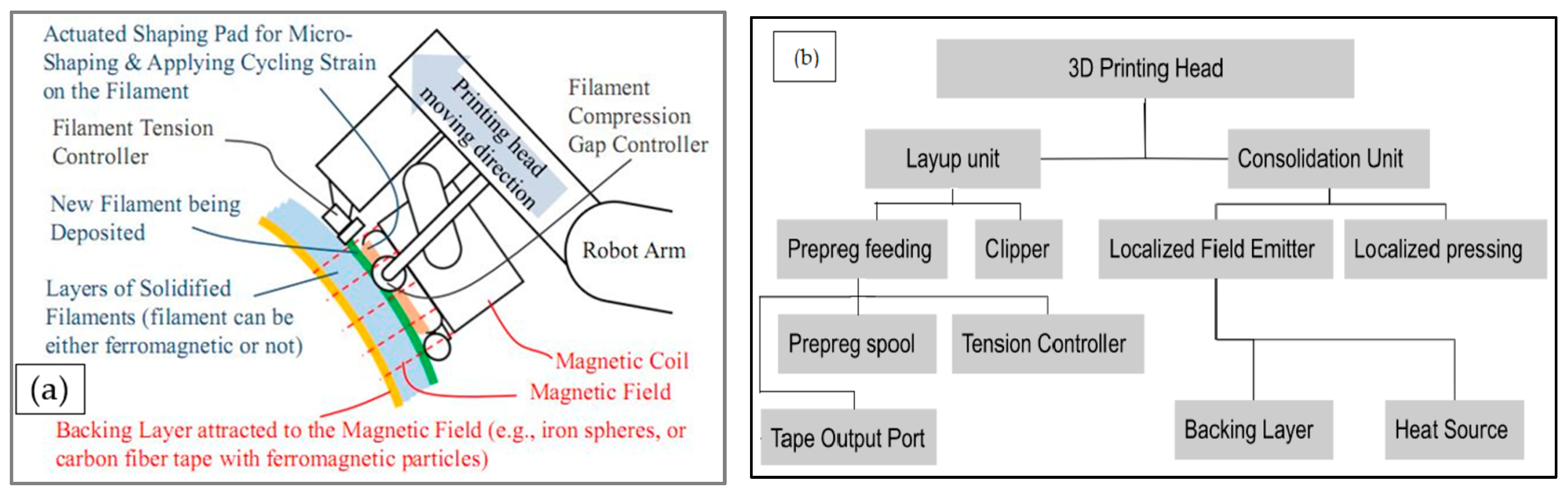
2.2.4. MCFA-AM Process

Both the CFRP and ZT-CFRP laminates were printed using an in-house-developed MCFA-AM 3D-printing head prototype. Note this MCFA-AM printing-head design can also work on thermoplastic CFRP tapes, in addition to the thermoset CFRP tapes used in this study. Figure 5 depicts a schematic of the novel MCFA-AM printing head (i.e., printhead) proposed in the patent publication [9] and a block diagram showcasing the main components. A printhead designed based on the novel MCFA-AM method was mounted on a six-degrees-of-freedom robotic arm (Motoman GP 7 Robot Arm form Yaskawa America, Inc., Waukegan, IL, USA), which was programed to move the MCFA-AM printhead along a predetermined straight-line path (for this experiment, the MCFA-AM printhead was operated at a constant height and the clamping anchor was adjusted after stacking each prepreg layer) to produce the straight/flat laminate samples. After making the prepregs, it took approximately 45 min to use the robotic MCFA-AM-printer prototype to print the stack of prepregs onto a CFRP or ZT-CFRP laminate and perform post-cleaning. A magnetic compaction force of 13.72 N was measured against a pressing area of 17.56 mm2, which yielded a compaction pressure of 0.78 bar (average), which in turn was utilized to compress and stack the prepregs at a printhead speed of 2.82 mm/s. The steps followed are described below:
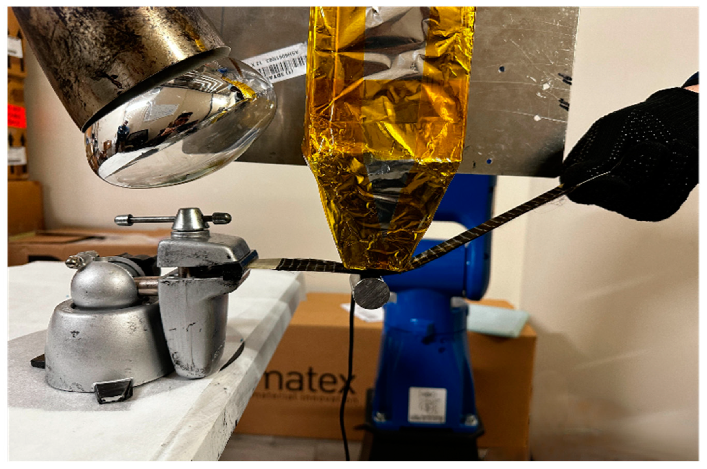
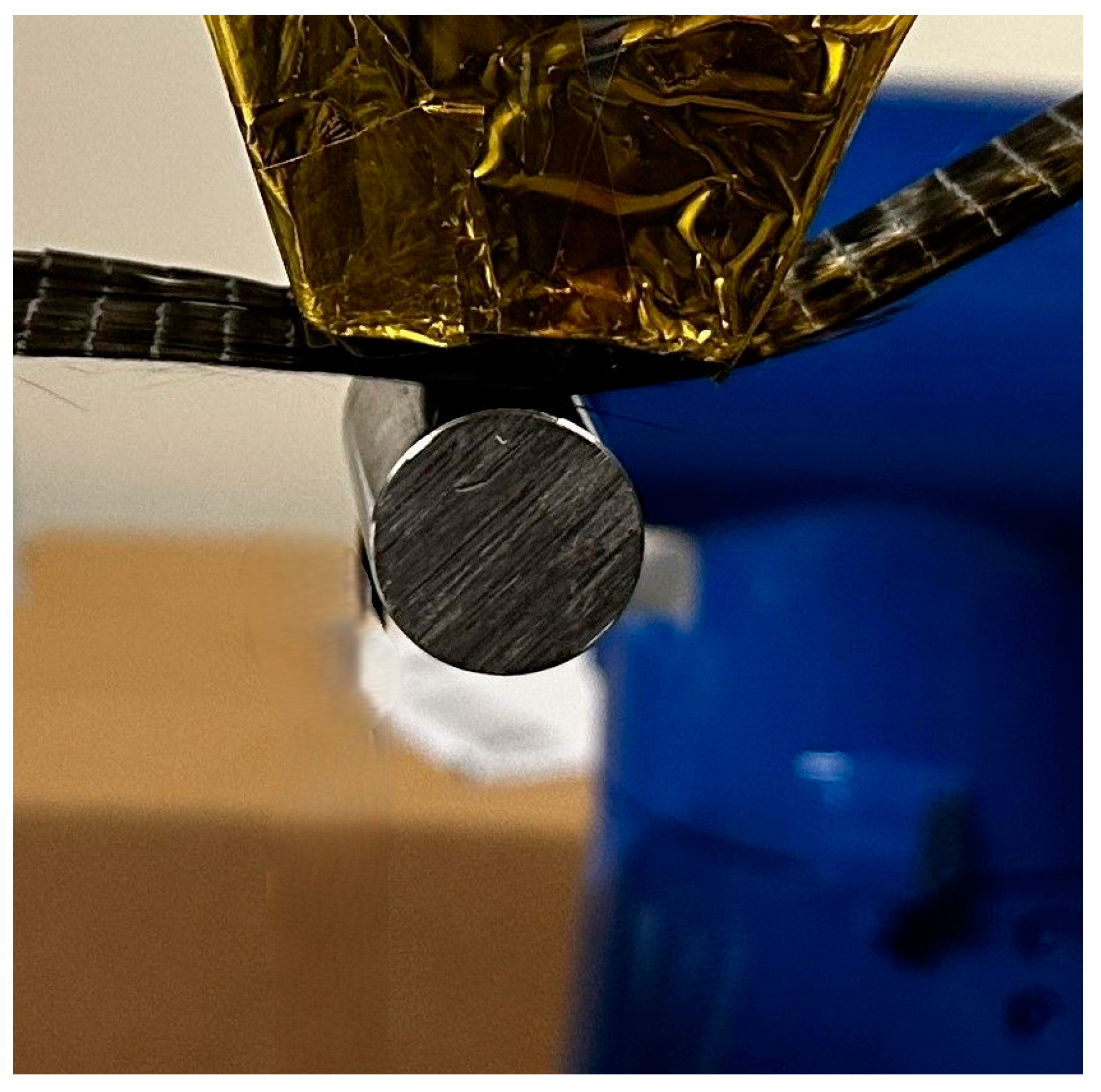
  • Step 1: one end of a ply of ZT-CFRP prepreg tape is anchored; the MCFA-AM printhead, with the magnetic field emitter switched on to a desired field strength to attract the backing article, smoothly driven from one end to the other by the robot arm, is used to position, compact, and cure (solidify) the ZT-CFRP-prepreg tape into a lamina in free space (air) (see Figure 6).
  • Step 2: reduce the magnetic field to release the backing article (it was collected by hand for this current underdevelopment prototype, but it will have an automatic collecting unit in the future, fully developed MCFA-AM printer); load a new layer of prepreg on top of the previous cured layer, and increase the magnetic field to a desired field strength to attract the backing article to clamp the new layer against the previously cured layer.
  • Step 3: the MCFA-AM printhead, with the magnetic field emitter switched on to a desired field strength to attract the backing article, smoothly driven from one end to the other by the robot arm, is then used to lay down, compact, and cure a new layer of ZT-CFRP-prepreg tape on top of the aforementioned cured ZT-CFRP layer.
  • Step 4: repeat Step (2) and Step (3) until the desired layers of CFRP prepreg are compacted and cured into a CFRP-laminate part.
  • Step 5: reduce the magnetic field and release the backing article; detach the cured/solidified ZT-CFRP laminate part from the anchoring fixture.
A 250-watt (120 V) heat lamp was used to induce the desired curing temperature, 140 °C on the fast-curing ZT-CFRP prepreg tape, and it was set in place pointing to the compaction spot, where the magnetic compaction force was exerted on the prepreg.
Similar to the OOA-VBO cured samples, before the ILSS tests were performed on the samples, all the laminates were further subjected to 4 h of post-curing to ensure full curing of the resin and to yield a fair experimental comparison among all samples.
Figure 6 shows the robot-arm-driven MCFA-AM printer (under development), to which a tape-like feedstock or filament (e.g., CFRP prepreg or ZT-CFRP prepreg) was clamped/anchored on one end, while the other end was fed by hand, and the tape was held in place and compressed by a backing article (metallic rod) attracted by a magnetic field emitter (sheathed with aluminum foil). The heat lamp was mounted pointing at the compaction region. Figure 7 displays a zoomed-in image that shows the backing article and the spot where it was clamped. The printhead traversed the length of the prepreg, from the anchored end to the free end, while the tapes were compacted and cured simultaneously.

2.2.5. No-Pressure-3DP Process

The no-pressure-3DP process involved the performance of similar processing physics to the typical FDM process. In the no-pressure-3DP process, the new uncured prepreg tape is deposited on top of either a flat printing bed or an already-cured layer with zero compaction pressure, and heat is used to simultaneously cure the new prepreg during the deposition process. In order to produce a CFRP laminate cured under zero compaction pressure, neither magnetic compaction force nor vacuum pressure were applied onto the prepregs while stacking and curing multiple plies of CFRP prepreg together. Instead, they were placed on top of a flat-plate substrate (i.e., an aluminum plate), with white parchment paper in between the plate and the prepreg, while they were gently laid down (without any significant compaction force) by a roller to set each layer straight on the stack of prepreg,. At the same time, they were heated by a lamp at 140 °C to ensure sufficient curing continuously. Additionally, to ensure full curing of the laminate before the longitudinal compression test, it underwent 4 h of post-curing. Figure 8 shows a cross-section of the sideline of a no-pressure CFRP laminate. Several voids are distinctly visible, which would have compromised its strength.

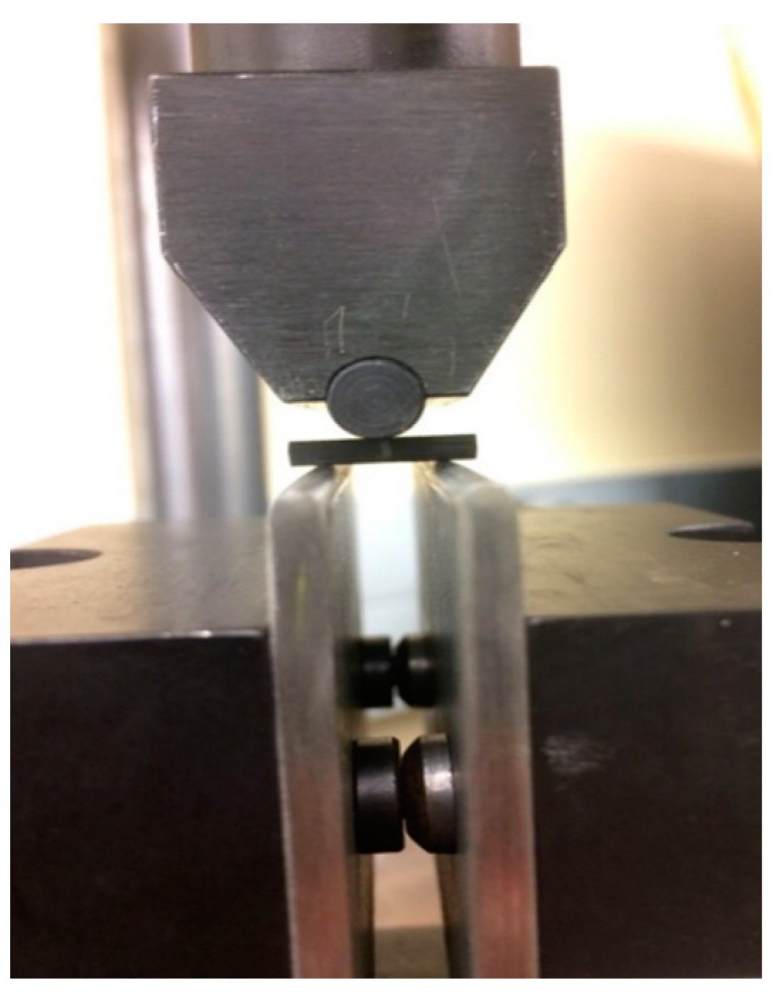
2.2.6. Short-Beam Shear-Testing Method for ILSS

The SBS (short-beam shear) test (ASTM D2344/D2344M−16) was used to determine the ILSS values of all the samples. The SBS test is a three-point bending test, with a span width of 4 times of the sample thickness; theoretically, the setting creates the highest shear stresses on the midplane of the specimen, resulting in shear failure in the interlaminar region. A TINIUS OLSEN Super “L” Universal Testing Machine with a 12,000 lbf (53,379 N) load cell and crosshead-loading rate of 1.0 mm/min was used to perform tests with 5 or more sample specimens for each different type of laminate. The 5 best data values were retained for results and analysis. As shown in Figure 9, the sample was centered on two 3-mm-diameter supports, each with a 10-mm span width. The supports and loading nose were set to be parallel and level. The ILSS value was calculated using Equation (1), where Pmax is the maximum loading in N; w and t denote the sample width and thickness in mm, respectively.
I L S S = 0.75 × P m a x / ( w × t )
Note that the ILSS test measured the apparent shear strength value rather than the pure shear strength, since the sample was also subjected to other stresses, strains, and stress concentrations due to the metal fixtures; however, it is a widely used method to relatively compare composite laminate samples with similar material compositions and identical dimensions, using identical machine and fixture settings.

3. Results and Analysis

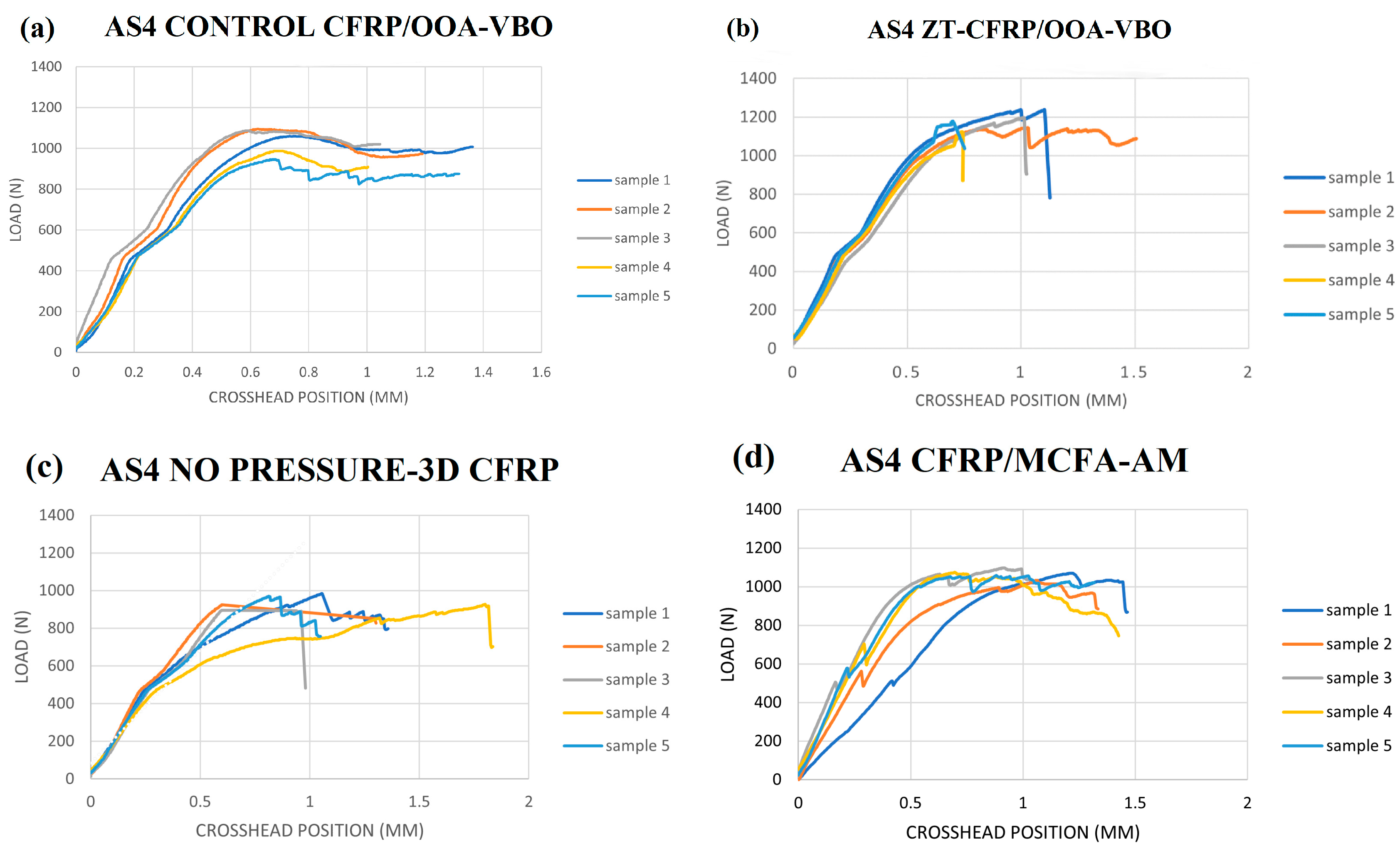
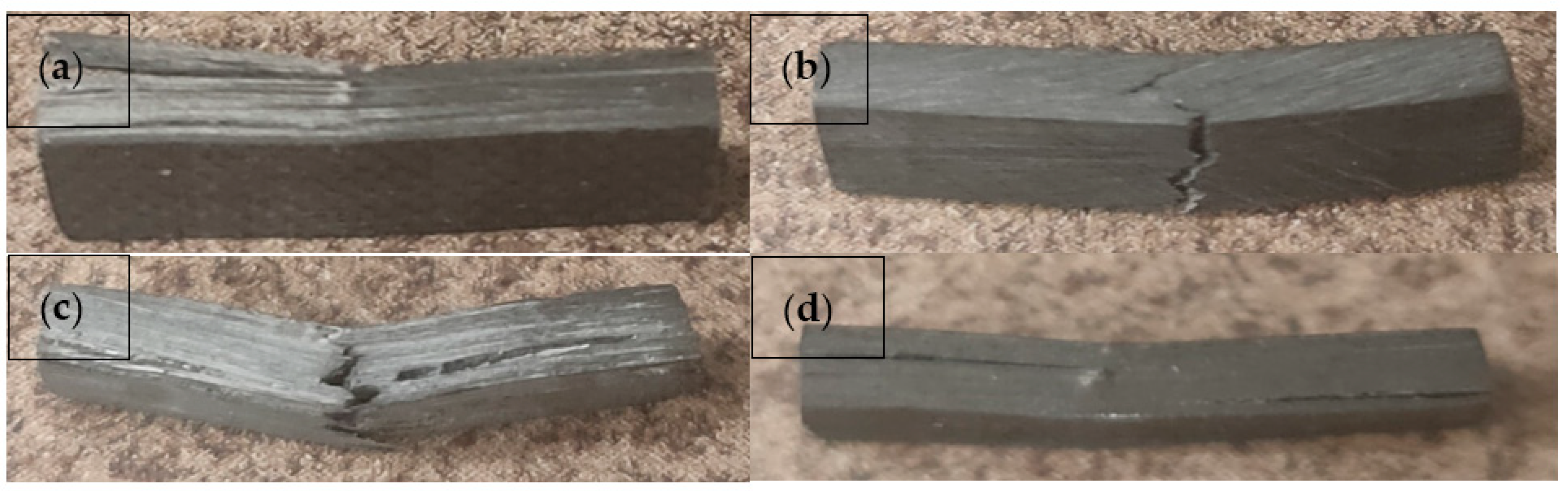
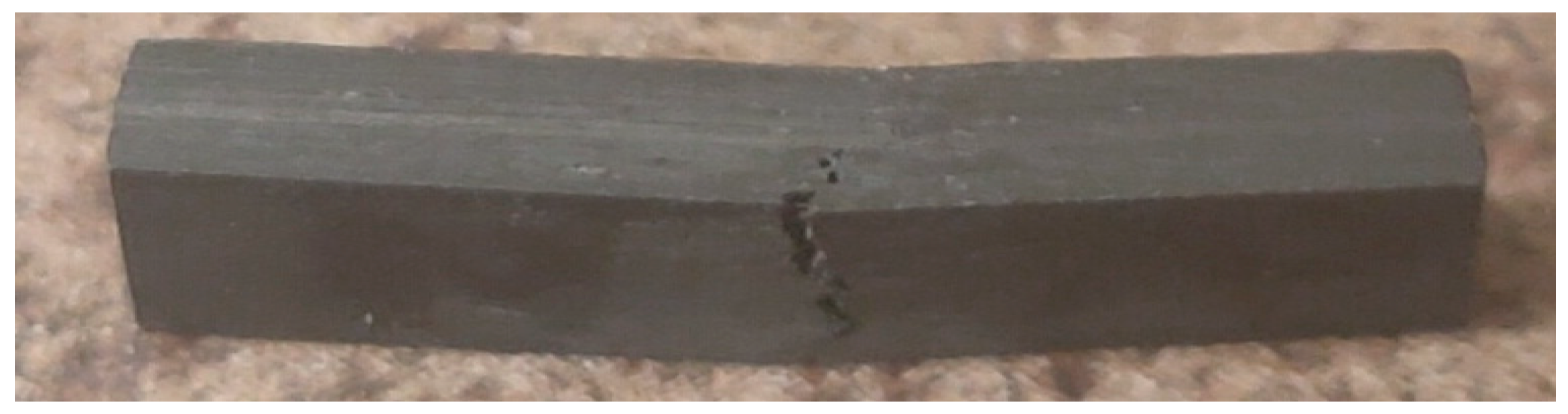
3.1. Short-Beam-Shear-Test Data and Sample Fracture Modes

The amount of fiber in a fiber-reinforced composite directly corresponds to some of the mechanical properties of the composite. Theoretically, a higher fiber-volume fraction (FVF) yields almost linearly increased tensile and compressive strengths, but not necessarily increases in the ILSS of the composite. The ILSS is more dominated by the matrix, voids, and matrix–fiber interfacial bonding if no nanoparticle reinforcement is considered. From the perspective of controlling the FVF of a FRP prepreg or laminate, the fiber-volume fraction can be calculated using Equation (2).
F V F = ( N o .   o f   p l i e s   o f   f a b r i c s   ×   A ω ) / ( ρ f   ×   t l a m )
where Aw = the areal weight of a ply of fabric in g/cm2, tlam = the thickness of the laminate in cm, and ρ f = the density of the fiber in g/cm3. Each layer of the prepreg’s thickness can be determined as t l a m / N o .   o f   p l i e s   o f   f a b r i c s . The carbon fabric’s areal weight and carbon-fiber density were provided by the manufacturer, and they were 0.019 g/cm2 and 1.79 g/cm3, respectively. Furthermore, the FVF of a single prepreg used in the MCFA-AM method was maintained in such a way that they all retained 53% FVF. To achieve this, a gage-controlled conduit was used to slide the fully impregnated prepregs through to remove the excessive resin and control the final prepreg thickness. The sample sizes were kept the same for all the laminate types, with a specimen thickness of 2.5 mm, a specimen width of 5.0 mm, and a specimen length of 15.00 mm. The measurement error was ±3% for the individual samples. Figure 10 and Figure 11 display the force vs. crosshead-position plots for all the different laminate types during the SBS test. The detailed data values, with the types of failure, are presented in Appendix A.
Many curves can be observed on the plots, reaching peak values almost in a linear manner and then continuously dropping, with slight oscillations, before stopping. This type of curve trend can be explained as a process in which a thick, short beam was gradually delaminated into multiple thinner short beams. Some of the samples also monotonically reduced in strength after the initial failure. A few of the curves had a sudden drop to more than 30% of the loading drop-off value after peaking, possibly indicating different fracture modes, other than pure delamination, which would have caused the short beam to suddenly lose its mechanical function almost completely. For the ZT-CFRP/OOA-VBO samples, the CNF z-threads formed an interlocking network between carbon fibers and tended to intervene by preventing or redirecting the propagation of resin cracks, resulting in an almost consistent maximum loading until multiple small fractures ultimately led to complete fiber breakage. The MCFA-AM-printed ZT-CFRP/MCFA-AM sample’s curves showed similar behavior, with slight fluctuations after reaching the maximum loading (Figure 11). The different failure modes for all the laminate types are shown in Figure 12 and Figure 13.
The ZT-CFRP/OOA-VBO sample (Figure 12b) had a fiber-tension-failure mode similar to that of ZT-CFRP/MCFA-AM sample (Figure 13). In contrast, the CFRP/OOA-VBO and CFRP/MCFA-AM had quite standard interlaminar shear failures (Figure 12a,d, respectively). The no-pressure-3DP CFRP sample (Figure 12c) was shown to have undergone both interlaminar shear and tension failure simultaneously.
The ILSS test data, computed based on Figure 10, are tabulated and comprehensively discussed, together with the other factors (such as morphology, void, and failure modes) in the Discussion section.

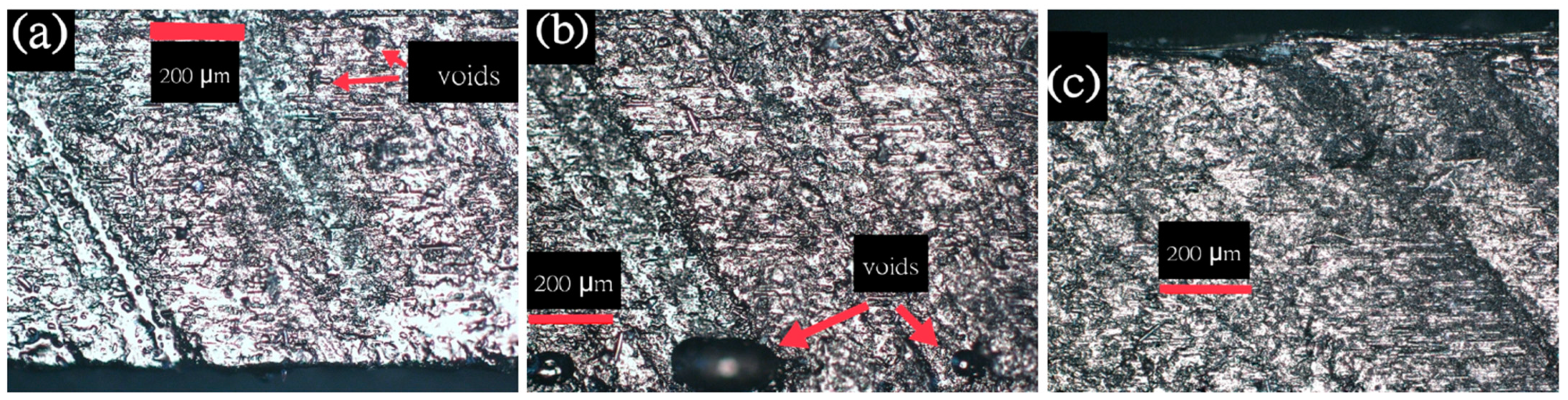
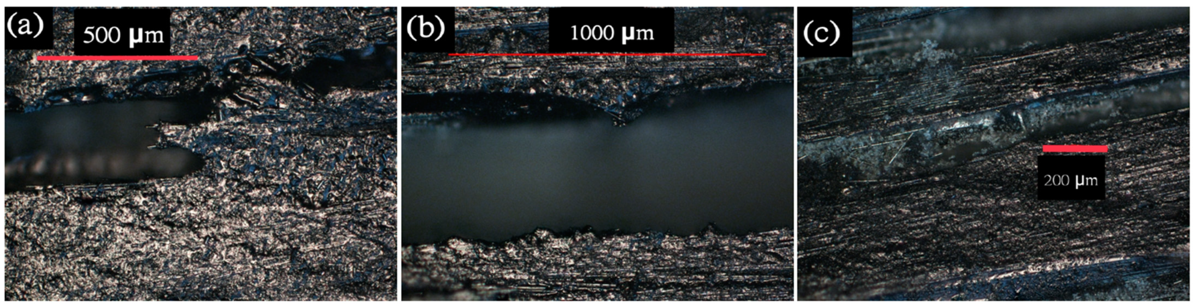
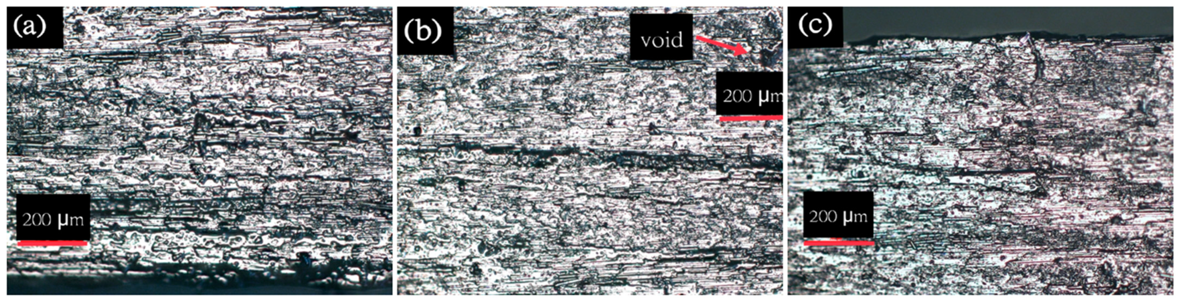
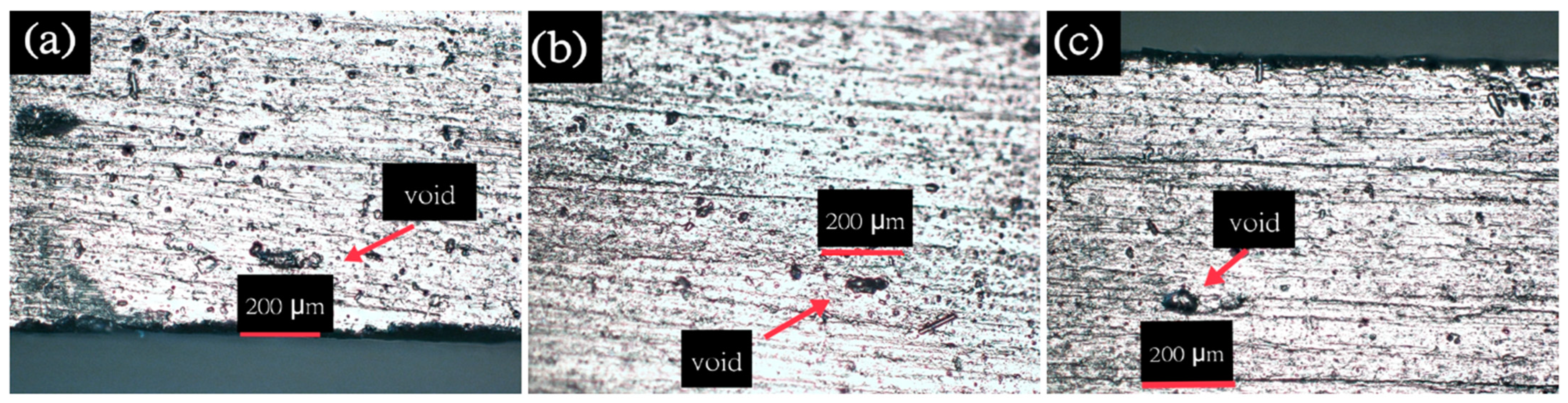
3.2. Microscopic Morphology

One of the primary reasons why samples undergo interlaminar-shear-strength failure is delamination by shear. The other kinds of failure include, but are not limited, to fiber micro buckling (i.e., fiber compressive failure) and fiber tensile breakage. In a previous study, the CNF z-threads interlocked between the carbon fibers and provided additional transversal stability support to the carbon fibers, making the ZT-CFRP composite laminates more resilient to interlaminar shear stress [25] and fiber micro buckling [20]. This may help to explain why all the ZT-CFRP laminates had better ILSS values than all the CFRP laminates, despite the different manufacturing methods tested in this study.
The crack propagation in sample 1 and the delamination direction in sample 2 are shown in Figure 13 for the control CFRP/OOA-VBO laminate. Figure 14b shows an overall interlaminar delamination with a split into intralaminar delamination (i.e., crack propagation between individual carbon fibers within the same layer of the CFRP prepreg) at the end of the sample. Figure 14c shows a 1000× magnified image that highlights the absence of any CNF in the control CFRP samples, demonstrating the reason for the intralaminar delamination, interlaminar delamination, and easy crack propagation. On the other hand, ZT-CFRP samples possess more durability and resilience against interlaminar shear stress, which prevents them from completely failing through interlaminar and intralaminar delamination; rather, they hold on until failure through fiber breakage. Figure 15 and Figure 16 display the carbon-fiber-breakage direction, the overall macroscopic-laminate-fracture direction (about 45 degrees of typical tension failure, which can also be seen in Figure 13), and the presence of pulled-off broken CNFs in the fractured region, for various ZT-CFRP/MCFA-AM samples.
For the void-content calculation, one random sample was selected from each of the laminate types and three separate microscopic pictures were taken from a single spot on the side of each sample. To improve the visibility of the voids, the spots were marked with a black marker pen, with ink that reflected differently from the resin and carbon fiber under the microscope, highlighting the presence of the voids (since the voids were not painted with marker pen) in the samples. For the computation of the void content, each void was assumed to be of an elliptical shape with the lengths of the major axis and minor axis denoted as a and b, respectively. In order to determine the void content by area, the area of the voids was divided by the total area of an individual microscopic spot. Figure 17, Figure 18, Figure 19, Figure 20 and Figure 21 display the 100× magnification images with the voids for all the laminate types.
Figure 22 displays a comparison plot of the void contents of all the laminate types. The detailed void-area-calculation data are presented in Table A6 in Appendix A. The number of voids was highest in the no-pressure-3DP CFRP samples, since they were printed by fusion only and without any compaction pressure; and the void content was about 23.94% with respect to the whole area in the image (this may have been different in the other spots of the no-pressure-3DP CFRP samples, since the fusion mechanism is more susceptible to many uncontrolled factors in the materials and the processing environment). The lowest amount of voids was found in the laminates manufactured via the OOA-VBO method, since they had been cured at 0.82 bar of compaction pressure and under vacuum to remove the gas and/or volatiles inside the prepreg stacks. The void contents of the CFRP/OOA-VBO and ZT-CFRP/OOA-VBO samples were 1.37% and 1.06%, respectively. The samples printed by the novel robotic MCFA-AM printer with 0.78 bar of magnetic compaction pressure also had few void areas. The void contents were 1.36% and 3.87% for the CFRP/MCFA-AM and ZT-CFRP/MCFA-AM samples, respectively. It was also very interesting to notice that the CFRP/OOA-VBO and CFRP/MCFA-AM had the very similar void contents, of 1.37% and 1.36%, respectively. The void study showed that the MCFA-AM 3D printing process with 0.78 bar of magnetic compaction pressure achieved similar void-content control to the OOA-VBO process. In the future, in terms of void-content control, the novel robotic MCFA-AM process has the potential to be further improved in order for it to exceed the OOA-VBO process, and even the other high-pressure molding processes, such as the RTM and autoclave processes.

4. Discussion

Table 3 displays the ILSS-test data for all the different kinds of sample, along with their processing-pressure settings, FVFs, void contents, processing times, and CNF-z-thread concentrations in the matrix. In terms of the composite-laminate manufacturing-method comparison, the MCFA-AM 3D-printing method delivered laminates with comparable ILSS and void contents to those in the laminates produced by the OOA-VBO process, despite the use of the ZT-CFRP prepreg or the traditional CFRP prepreg. It seems that the localized magnetic compaction pressure and the in situ curing applied during the MCFA-AM 3D-printing process was very effective in ensuring that the void content was similar to that in the OOA-VBO process; hence, both processes resulted in similar ILSS values. On the other hand, as expected, the no-pressure-3DP samples, representing typical 3D-printing processes (such as the FDM), showed substantially inferior void contents (23.94%) and ILSS values (53.99 MPa) compared with the void content (1.06%) and ILSS (62.60 MPa) of the control CFRP/OOA-VBO samples. The no-pressure-3DP samples were also substantially inferior to the CFRP samples printed by MCFA-AM, whereas the CFRP/MCFA-AM samples had a void content of 1.36% and an ILSS of 62.83 MPa.
Based on Table 4, the use of proven advanced nanomaterials, such as the ZT-CFRP, as the prepreg in the production of composite laminates was found to be a highly effective and consistent method to improve the ILSS. The ZT-CFRP laminates, regardless of the manufacturing methods used, consistently outperformed the traditional CFRP laminates; the improvements in the ILSS due to the use of the ZT-CFRP prepreg to replace the traditional CFRP prepreg, were about 12.8% and 10.97% when manufacturing the laminates with the OOA-VBO process and with the MCFA-AM 3D-printing process, respectively. Furthermore, the ZT-CFRP samples, regardless of whether they were manufactured by OOA-VBO or MCFA-AM, consistently showed tension-failure mode during the short-beam shear (SBS) test, rather than the interlaminar-shear-failure mode. This indicated that the ZT-CFRP was very effective in preventing interlaminar shear failure, and the ILSS value could have been higher if the tension-failure mode had been delayed or prevented, before the interlaminar-shear-failure mode occurred, by using stronger carbon fibers or by modifying the SBS-test fixture and sample dimensions to reduce the local stress concentration near the center of the short-beam sample.
Figure 23 depicts the parameters that contributed to the improved ILSS in this study. Using a higher compaction pressure to reduce the void content and applying advanced nanocomposites, such as the ZT-CFRP, when combined appropriately, can provide synergetic effects with which to improve the ILSS of composite laminates.
Regarding the convenience, manufacturing speed, and cost, the MCFA-AM 3D-printing process has significant advantages over the OOA-VBO molding process. As shown in Table 4, the time taken to manufacture a composite laminate using the OOA-VBO molding process was about 120 min, and this process also requires the use of aluminum molding, along with many consumables, such as vacuum bags, tubing/vacuum channels, peel plies, distribution media, and sealant tape (see Figure 4). On the other hand, the time taken to print a composite laminate using the MCFA-AM was about 45 min, and this method does not require the use of consumables or molds. The production time saved by using the MCFA-AM process is about 62.5%; the production speed when using the robotic MCFA-AM is about 2.67 times faster than that in the OOA-VBO process. The cost savings in terms of consumables and labor when using the robotic MCFA-AM printing process to replace the commonly used OOA-VBO molding process are also very extensive. Table 5 compares the advantages and disadvantages of the OOA-VBO, traditional FDM, and MCFA-AM methods to highlight the basic differences between them.
Based on Table 4 and the discussion above, the ZT-CFRP/MCFA-AM samples clearly stood out from the rest of the sample types. According to a simple comparison of the ZT-CFRP/MCFA-AM samples with the benchmark of the control CFRP/OOA-VBO samples, the ZT-CFRP/MCFA-AM case had an improvement of 11.34% in the ILSS mean, a 2% reduction in the COV of the ILSS (i.e., it was more reliable and consistent), a 2.81% increase in the void content (this void increase is not desirable, but the ILSS performance was not affected, thanks to the ZT-CFRP material’s mechanically-interlocked microarchitecture), prevented the interlaminar- and intralaminar-shear-failure mode, increased the composite parts’ production speed to 2.67 times, and reduced the costs of the labor, tools, and consumables. Furthermore, the CFRP/MCFA-AM provides a more effective approach to using materials and consumables, and it is potentially a more sustainable and greener composite-manufacturing process, although future studies on this topic are required.

5. Conclusions

The CFRP and ZT-CFRP laminates were printed using the novel robotic MCFA-AM process under 0.78 bar of localized magnetic compaction pressure, and their void contents and ILSS were compared with those of other laminate types manufactured under various compaction pressures. The traditional CFRP manufactured by the OOA-VBO process, a common molding process for manufacturing structural-composite parts, was used as the control/benchmark case for comparison. All the different kinds of sample were analyzed microscopically to determine the void contents and the morphologies of the fracture sites. This in turn allowed a better understanding of the effects of CNF z-threads and void-content control on the ILSS and shear-fracture mechanism within the printed or molded laminates.
The use of nanomaterials was consistently found to be effective in improving the composites’ properties. For the ZT-CFRP samples printed using MCFA-AM, the ILSS results obtained were almost equal to those of the ZT-CFRP samples molded with OOA-VBO and cured under a full vacuum (about 0.82 bar) applied inside a vacuum bag and under the same compaction pressure as that applied on the stack of prepregs. The former had an improvement of about 11.34% in the ILSS, which was only 1.46% less than the improvement of the latter, compared with the ILSS of the control case (i.e., the traditional CFRP molded through the OOA-VBO method). Furthermore, both the macroscopic failure-mode analysis and the microscopic morphology indicated that the CNF z-threads prevented the ZT-CFRP samples from undergoing the typical shear delamination encountered by traditional CFRP samples, regardless of whether they are printed or molded; instead, the ZT-CFRP samples failed due to fiber-tension failure before any shear delamination could occur. As the OOA-VBO process has the flow-distribution medium to remove excessive resin, it manufactured ZT-CFRP samples with slightly higher carbon-fiber-volume fractions than the ZT-CFRP samples printed by the MCFA-AM method; hence, the higher carbon-fiber volume proportionally increased the ILSS values of the ZT-CFRP samples, which were dominated by the fiber-tension failure mode. On the other hand, despite the slight differences in carbon-fiber-volume fraction between the traditional CFRP samples manufactured by the OOA-VBO molding process and those manufactured by the robotic MCFA-AM 3D-printing process, the traditional CFRP samples had almost the same ILSS mean values; this was due to the fact that the interlaminar- and intralaminar-shear failures, which typically occur in traditional CFRP laminates, are usually dominated by the resin’s shear strength and void content, but not the carbon-fiber-volume fraction. Based on the measurements, fracture mechanism, morphology, and explanation, it is evident that the ILSS and shear-fracture performance of CFRPs can be significantly enhanced using CNF z-threads,. In future studies, a compaction pressure higher than 0.78 bar and the use of ZT-CFRP with a higher carbon-fiber-volume fraction or stronger carbon fibers could further enhance the ILSS values (evaluated by Short Beam Shear test method) of ZT-CFRP samples printed by MCFA-AM, beyond those that the current study was able to yield.
The novel MCFA-AM 3D printing process, by using the magnetic compaction pressure of 0.78 bar, effectively reduced the void content to close to that of the OOA-VBO’s void-control performance, and enhanced the laminate-production speed to 2.7 times that of the OOA-VBO molding process. The experimental results showed that by combining advanced nanomaterials technology, such as the ZT-CFRP, with the novel MCFA-AM free-form 3D-printing process, compared with traditional CFRPs manufactured by using the OOA-VBO molding process, it possible to achieve similar void contents, increase the ILSS by 11.34%, enhance the production speed by 2.7 times, generate cost savings in terms of molding tools and consumables, enjoy the convenience of 3D printing, and obtain composite laminate products for structural applications with repeatable and consistently high performance. This new approach could also provide a more sustainable and greener manufacturing approach due to its ability to save on consumables and materials usage and to build stronger composite parts.
In the future, there is ample room for improvement in the robotic MCFA-AM printer’s construction and control. The improved synchronization between the printing speed, dynamic magnetic compaction control, multi-stage curing control, automated prepreg filament feeder, automated anchor unit, and synchronized multiple printheads could allow the production of higher-quality laminates or functionally-graded composite structures. The current robotic MCFA-AM printer is still a prototype, and several accessory components and the control algorithm are yet to be incorporated into its design and construction. Further advancements in nanomaterials, such as the ZT-CFRP, or other material systems (e.g., reusable thermoplastic matrix ZT-CFRP), and their availability for the MCFA-AM 3D printing feedstock, could be studied using a broad range of polymer and fiber materials. Another area of interest is the development of a modified automated RFA-process device to simultaneously produce the desired ZT-CFRP prepreg to be fed to the robotic MCFA-AM printer. These future improvements will allow an enhanced degree of freedom in optimally tailoring the composite’s structure through highly versatile additive manufacturing and on-demand, tailorable nanocomposite technology. The great portability and small footprint of the robotic MCFA-AM printer can also expand digital manufacturing capability to remote or difficult-to-reach sites/fields to print high-strength composite parts on-demand. The integration of additive manufacturing, advanced nanomaterials, robotics, digital manufacturing, and artificial intelligence could be the future development direction for next-generation composite manufacturing.

6. Patents

There are no patents resulting from this paper. However, this paper used knowledge or methods described in the following patents, invented by the co-author/corresponding author:

Author Contributions

Conceptualization, K.-T.H.; methodology, M.R.I., W.T. and R.W.; software, W.T.; validation, data analysis, investigation, data curation, and writing—original draft preparation, M.R.I.; writing—review and editing, W.T., R.W. and K.-T.H.; supervision, project administration, and funding acquisition, K.-T.H. All authors have read and agreed to the published version of the manuscript.

Funding

This research was partially funded by the National Science Foundation (award number: 2044513), Alabama Department of Commerce through the Alabama Innovation Fund (award number: 150436), and NASA Alabama Space Grant Consortium Fellowship award (NASA’s Alabama Space Grant Consortium’s Training Grant 80NSSC20M0044), University of South Alabama Research and Scholarly Development Grant Program (award no. 20-0274).

Institutional Review Board Statement

Not applicable.

Informed Consent Statement

Not applicable.

Data Availability Statement

Please see Appendix A for detailed testing data.

Acknowledgments

The authors are grateful for the AS-4 carbon fiber materials provided by Hexcel Corp., the Araldite LY 3031, and Aradur 3032 provided by Huntsman Corp., and the surfactants provided by BYK USA, Inc.

Conflicts of Interest

In addition to the patents already listed above, the authors declare no potential conflict of interest. The funders had no role in the design of the study; in the collection, analyses, or interpretation of data; in the writing of the manuscript; or in the decision to publish the results.

Appendix A

Table A1. AS4 ZT-CFRP/MCFA-AM samples.
Sample
Order
Compaction PressureWidthThicknessArea
(mm2)
Ultimate
Force (N)
FVF (%)ILSS (MPa)Failure ModeRelative ILSS Improvement w.r.t. Control CFRP (%)
Sample 10.78 bar5.162.5413.111228.3353 ± 170.27Tension failure (fiber breakage)+11.34%
Sample 20.78 bar5.122.5413.011206.0853 ± 169.53Tension failure (fiber breakage)
Sample 30.78 bar5.202.5213.101232.6253 ± 170.57Tension failure (fiber breakage)
Sample 40.78 bar5.112.4912.721139.1853 ± 167.17Interlayer shear (fiber delamination)
Sample 50.78 bar5.142.5012.851212.3753 ± 170.73Tension failure (fiber breakage)
Mean 5.152.5212.961203.7253 ± 169.65
STDEV 0.040.010.0616.05 0.61
Maximum 5.202.5413.111235.00 70.58
Minimum 5.112.4912.721139.18 69.53
COV (%) 0%0%0%1% 1%
Table A2. AS4 ZT-CFRP/OOA-VBO samples.
Sample OrderCompaction PressureWidthThicknessArea
(mm2)
Ultimate
Force (N)
FVF (%)ILSS (MPa)Failure ModeRelative ILSS Improvement w.r.t. Control CFRP (%)
Sample 10.82 bar4.982.5112.501238.4255 ± 174.30Tension failure (fiber breakage)+12.8%
Sample 20.82 bar4.982.5012.451139.1755 ± 168.63Tension failure (fiber breakage)
Sample 30.82 bar5.042.4812.521198.6655 ± 171.80Tension failure (fiber breakage)
Sample 40.82 bar5.002.4912.451118.9855 ± 167.40Tension failure (fiber breakage)
Sample 50.82 bar5.022.4812.461178.3755 ± 170.92Tension failure (fiber breakage)
Mean 5.002.5012.531174.7355 ± 170.65
STDEV 0.030.020.0349.95 2.85
Maximum 5.042.5112.521238.42 74.30
Minimum 4.982.4812.451118.98 67.40
COV (%) 1%1%0%4% 4%
Table A3. AS4 CFRP/no-pressure-3DP samples.
Sample OrderCompaction PressureWidthThicknessArea (mm2)Ultimate
Force (N)
FVF (%)ILSS (MPa)Failure ModeRelative ILSS Improvement w.r.t. Control CFRP (%)
Sample 10 bar5.022.5312.70982.8453 ± 158.04Interlayer shear−13.75%
Sample 20 bar5.032.5312.73924.6753 ± 154.48Tension failure and interlayer shear
Sample 30 bar5.112.5112.83890.6453 ± 152.06Interlayer shear
Sample 40 bar5.052.5412.83927.6253 ± 154.23Interlayer shear
Sample 50 bar5.132.5413.03889.0253 ± 151.17Interlayer shear
Mean 5.072.5312.82922.9653 ± 153.99
STDEV 0.010.050.0746.62 3.00
Maximum 5.132.5413.03982.84 58.04
Minimum 5.022.5112.70889.02 51.17
COV (%) 0%1%1%5% 6%
Table A4. AS4 control CFRP/OOA-VBO samples.
Sample OrderCompaction PressureWidthThicknessArea (mm2)Ultimate
Force (N)
FVF (%)ILSS (MPa)Failure ModeRelative ILSS Improvement w.r.t. Control CFRP (%)
Sample 10.82 bar5.022.5012.551060.5456 ± 163.38Interlayer shear N/A
Sample 20.82 bar5.012.4612.321095.6956 ± 166.70Compressive failure
Sample 30.82 bar5.042.4812.421087.3856 ± 165.66Interlayer shear
Sample 40.82 bar4.982.4812.35987.3656 ± 159.96Interlayer shear
Sample 50.82 bar5.002.4713.35944.3556 ± 157.35Interlayer shear
Mean 5.012.4812.601035.0656 ± 162.60
STDEV 0.020.020.1218.37 1.65
Maximum 5.042.5013.351095.69 66.70
Minimum 4.982.4612.32944.35 57.35
COV (%) 0%1%1%2% 3%
Table A5. AS4 CFRP/MCFA-AM samples.
Sample OrderCompaction PressureWidthThicknessArea (mm2)Ultimate
Force (N)
FVF (%)ILSS (MPa)Failure ModeRelative ILSS Improvement w.r.t. Control CFRP (%)
Sample 10.78 bar5.052.5312.781068.3053 ± 162.69Interlayer shear+0.37%
Sample 20.78 bar5.042.5112.651033.0053 ± 161.25Interlayer shear
Sample 30.78 bar5.072.4812.571096.8653 ± 165.45Interlayer shear
Sample 40.78 bar5.032.5512.831074.0953 ± 162.78Interlayer shear
Sample 50.78 bar5.022.5512.801057.4253 ± 161.96Compressive failure
Mean 5.042.5212.731065.9353 ± 162.83
STDEV 0.020.030.131.99 2.12
Maximum 5.072.5512.831096.86 65.45
Minimum 5.022.4812.571033.00 61.25
COV (%) 0%1%1%3% 3%
Table A6. Statistical analysis of the optical microscopy images of voids taken at 100X magnification.
No. of
Image Spots
CFRP/MCFA-AM
Void Area πab (µm2)
ZT-CFRP/MCFA-AM
Void Area πab (µm2)
CFRP/No-Pressure-3DP
Void Area πab (µm2)
Control CFRP/OOA-VBO
Void Area πab (µm2)
ZT-CFRP/OOA-VBO
Void Area πab (µm2)
128,274.33421,676.984214,247.78016,022.12
210,995.5789,535.390720,00019,792.03412,566.37
300100,000017,592.92
Maximum28,274.33489,535.390720,00019,792.03417,592.92
Minimum10,995.5721,676.984100,000016,022.12
Total area14.4 × 105 µm214.4 × 105 µm214.4 × 105 µm214.4 × 105 µm214.4 × 105 µm2
Average void content1.36%3.87%23.94%1.37%1.06%

References

  1. Ashir, M.; Nocke, A.; Bulavinov, A.; Pinchuk, R.; Cherif, C. Influence of defined amount of voids on the mechanical properties of carbon fiber-reinforced plastics. Polym. Compos. 2019, 40, E1049–E1056. [Google Scholar] [CrossRef]
  2. Huang, H.; Talreja, R. Effects of void geometry on elastic properties of unidirectional fiber reinforced composites. Compos. Sci. Technol. 2005, 65, 1964–1981. [Google Scholar] [CrossRef]
  3. Zhang, J.; Taylor, T.; Shukla, L.; Yanagimoto, J. Rapid fabrication of 3D CFRP parts by hot forming of pre-cured CFRP sheets. Compos. Struct. 2021, 268, 113942. [Google Scholar] [CrossRef]
  4. Perrin, F.; Bureau, M.N.; Denault, J.; Dickson, J.I. Mode I interlaminar crack propagation in continuous glass fiber/polypropylene composites: Temperature and molding condition dependence. Compos. Sci. Technol. 2003, 63, 597–607. [Google Scholar] [CrossRef]
  5. Bureau, M.N.; Denault, J. Fatigue Resistance of continuous glass fiber/polypropylene composites: Consolidation dependence. Compos. Sci. Technol. 2004, 64, 1785–1794. [Google Scholar] [CrossRef]
  6. Blok, L.G.; Longana, M.L.; Yu, H.; Woods, B.K.S. An investigation into 3D printing of fibre reinforced thermoplastic composites. Additive Manufacturing. Addit. Manuf. 2018, 22, 176–186. [Google Scholar] [CrossRef]
  7. Fujihara, K. Influence of processing conditions on bending property of continuous carbon fiber reinforced PEEK composites. Compos. Sci. Technol. 2004, 64, 2525–2534. [Google Scholar] [CrossRef]
  8. Ranabhat, B. Magnetic Compaction Force Assisted Additive Manufacturing of Continuous Carbon Fiber Reinforced Polymer Composites and System Architecture Investigation Using System Modeling Language (SYSML). Ph.D. Dissertation, University of South Alabama, Mobile, AL, USA, 2020. [Google Scholar]
  9. Hsiao, K.-T. Method and Apparatus for 3D Printing. U.S. Patent US11426935B2, 30 August 2022. Available online: https://patents.google.com/patent/US11426935B2/en (accessed on 3 April 2023).
  10. Hull, C.W. Apparatus for Production of Three-Dimensional Objects by Stereolithography. Google Patents US4575330A, 11 March 1986. Available online: https://patents.google.com/patent/US4575330A/en (accessed on 3 April 2023).
  11. Yang, C.; Tian, X.; Liu, T.; Cao, Y.; Li, D. 3D printing for continuous fiber reinforced thermoplastic composites: Mechanism and performance. Rapid Prototyp. J. 2017, 23, 209–215. [Google Scholar] [CrossRef]
  12. Ning, F.; Cong, W.; Qiu, J.; Wei, J.; Wang, S. Additive manufacturing of carbon fiber reinforced thermoplastic composites using fused deposition modeling. Compos. Part B Eng. 2015, 80, 369–378. [Google Scholar] [CrossRef]
  13. Struzziero, G.; Barbezat, M.; Skordos, A.A. Consolidation of continuous fibre reinforced composites in additive processes: A review. Addit. Manuf. 2021, 48, 102458. [Google Scholar] [CrossRef]
  14. Wang, X.; Jiang, M.; Zhou, Z.; Gou, J.; Hu, D. 3D printing of polymer matrix composites: A review and prospective. Compos. Part B Eng. 2016, 110, 442–458. [Google Scholar] [CrossRef]
  15. Mallick, P.K. Fiber-Reinforced Composites, 3rd ed.; CRC Press: New York, NY, USA, 2007. [Google Scholar]
  16. Ueda, M.; Kishimoto, S.; Yamawaki, M.; Matsuzaki, R.; Todoroki, A.; Hirano, Y.; Le Duigou, A. 3D compaction printing of a continuous carbon fiber reinforced thermoplastic. Compos. Part A Appl. Sci. Manuf. 2020, 137, 105985. [Google Scholar] [CrossRef]
  17. Ming, Y.; Duan, Y.; Wang, B.; Xiao, H.; Zhang, X. A novel route to fabricate high-performance 3d printed continuous fiber-reinforced thermosetting polymer composites. Materials 2019, 12, 1369. [Google Scholar] [CrossRef] [PubMed]
  18. Ranabhat, B.; Kirmse, S.; Hsiao, K.-T. Feasibility Study of Novel Magnetic Compaction Force Assisted Additive Manufacturing (MCFA-AM) Methodology for Continuous Carbon Fiber Reinforced Polymer (C-CFRP) Composites. In Proceedings of the SAMPE (2019), Charlotte, NC, USA, 20–23 May 2019. [Google Scholar] [CrossRef]
  19. Hsiao, K.-T. Uncertainty modeling of residual stress development in polymeric composites manufactured with resin transfer molding process. In Proceedings of the IMECE2007, ASME International Mechanical Engineering Congress and Exposition (2007), Seattle, WA, USA, 11–15 November 2007. [Google Scholar] [CrossRef]
  20. Kirmse, S.; Kim, K.; Ranabhat, B.; Hsiao, K.-T. Effects of Carbon Nanofiber Z-Threads on the Longitudinal Compressive Strength of Unidirectional CFRP Laminates. In Proceedings of the SAMPE 2019, Charlotte, NC, USA, 20–23 May 2019. [Google Scholar] [CrossRef]
  21. Hsiao, K.-T.; Scruggs, A.M.; Brewer, J.S.; Hickman, G.; McDonald, E.E.; Henderson, K. Effect of carbon nanofiber z-threads on mode-I delamination toughness of carbon fiber reinforced plastic laminates. Compos. Part A Appl. Sci. Manuf. 2016, 91, 324–335. [Google Scholar] [CrossRef]
  22. Scruggs, A.M.; Kirmse, S.; Hsiao, K.-T. Enhancement of Through Thickness Thermal Transport in Unidirectional Carbon Fiber Reinforced Plastic Laminates due to the Synergetic Role of Carbon Nanofiber Z-Threads. J. Nanomater. 2019, 2019, 8928917. [Google Scholar] [CrossRef]
  23. Ranabhat, B.; Hsiao, K.-T. Improve the Through-Thickness Electrical Conductivity of CFRP Improve the Through-Thickness Electrical Conductivity of CFRP Laminate Using Flow Aligned Carbon Nanofiber Z-Threads. In Proceedings of the SAMPE 2018, Long Beach, CA, USA, 21–24 May 2018. [Google Scholar]
  24. Scruggs, A.M.; Henderson, K.; Hsiao, K.-T. Characterization of electrical conductivity of a carbon fiber reinforced plastic laminate reinforced with z-aligned carbon nanofibers. In Proceedings of the CAMX 2016, Anaheim, CA, USA, 26–29 September 2016. [Google Scholar]
  25. Kirmse, S.; Hsiao, K.-T. Enhancing the interlaminar shear strength of unidirectional carbon fiber reinforced plastic (CFRP) laminate using a nanofiber z-threading strategy. In Proceedings of the CAMX 2018, Dallas, TX, USA, 15–18 October 2018. [Google Scholar]
  26. Ranabhat, B.; Kirmse, S.; Johnson, M.; Hsiao, K.-T. Carbon nanofiber z-threaded carbon fiber reinforced polymer composite (ZT-CFRP) laminate parts produced using a magnetic compaction force assisted additive manufacturing (MCFA-AM). In Proceedings of the SAMPE 2020, Virtual, 8 June 2020. [Google Scholar] [CrossRef]
  27. Pyrograf-III Carbon Nanofiber. Available online: http://pyrografproducts.com/nanofiber.html#_PR-24-XT-HHT_Data_Sheet (accessed on 1 October 2018).
  28. Hsiao, K.-T.; Gangireddy, S. Investigation on the spring-in phenomenon of carbon nanofiber-glass fiber/polyester composites manufactured with vacuum assisted resin transfer molding. Compos. Part A Appl. Sci. Manuf. 2008, 39, 834–842. [Google Scholar] [CrossRef]
  29. Sadeghian, R.; Gangireddy, S.; Minaie, B.; Hsiao, K.-T. Manufacturing carbon nanofibers toughened polyester/glass fiber composites using vacuum assisted resin transfer molding for enhancing the mode-I delamination resistance. Compos. Part A Appl. Sci. Manuf. 2006, 37, 1787–1795. [Google Scholar] [CrossRef]
  30. Hsiao, K.-T. Apparatus and Method for Directional Alignment of Nanofibers in a Porous Medium. U.S. Patent US10556390B2, 11 February 2020. Available online: https://patents.google.com/patent/US10556390B2/en (accessed on 3 April 2023).
Figure 1. Illustration of ZT-CFRP structure.
Applsci 13 05914 g001
Figure 2. Radial flow alignment (RFA) process used to manufacture the ZT-CFRP-prepreg tape.
Applsci 13 05914 g002
Figure 3. Scanning-electron-microscope images of the delaminated surface of 1 wt% CNF z-threaded CFRP laminate produced by RFA technique: (a) 100× magnification; (b) 1000× magnification; (c) 5000× magnification (obtained from [23], with permission).
Applsci 13 05914 g003
Figure 4. OOA-VBO layup scheme used for the preparation of laminates.
Applsci 13 05914 g004
Figure 5. (a) The novel 3D-printing head (i.e., printhead) for the patented MCFA-AM method [9]. (b) Block diagram with the main printing-head components in the early development stage and their connections under a modularized system-construction map.
Applsci 13 05914 g005
Figure 6. Illustration of the under-development robot-arm-driven MCFA-AM printer: a tape-like feedstock or filament (e.g., CFRP prepreg or ZT-CFRP prepreg) is hand-fed (the mechanical feeder is under development) and held in place by a backing article (metallic rod) attracted by a proprietary magnetic field emitter (sheathed with aluminum foil), with a heat lamp (not turned on in this illustration) pointing at the compaction region.
Applsci 13 05914 g006
Figure 7. A zoomed-in image showing the tape/filament being lifted/compressed by the backing article attracted by the magnetic field emitter.
Applsci 13 05914 g007
Figure 8. Cross section cut of a no-pressure-3DP CFRP laminate.
Applsci 13 05914 g008
Figure 9. SBS testing-fixture setup with a sample.
Applsci 13 05914 g009
Figure 10. Load vs. Crosshead position plots of (a) control CFRP/OOA-VBO, (b) ZT-CFRP/OOA-VBO, (c) no-pressure 3D CFRP, (d) CFRP/MCFA-AM-laminate samples.
Applsci 13 05914 g010
Figure 11. Load vs. crosshead position of ZT-CFRP/MCFA-AM-laminate samples.
Applsci 13 05914 g011
Figure 12. Failure modes of the SBS-tested samples. (a) Control CFRP/OOA-VBO sample: interlayer-shear-failure mode. (b) ZT-CFRP/OOA-VBO sample: tension-failure mode. (c) No-pressure 3D CFRP sample: mixed-interlayer-shear-failure mode and tension-failure mode. (d) CFRP/MCFA-AM sample: interlayer-shear-failure mode.
Applsci 13 05914 g012
Figure 13. The SBS test of a ZT-CFRP/MCFA-AM sample showed the fiber-tensile-failure mode on the lower half section of the laminate instead of the expected standard delamination-failure mode.
Applsci 13 05914 g013
Figure 14. Microscopic pictures of delamination sites of control CFRP/OOA-VBO samples: (a) (100×) sample 1: crack propagation. (b) (100×) Sample 2: interlaminar delamination with a split into intralaminar delamination at the end of the sample. (c) (1000×) Sample 2 (same spot): intralaminar delamination with no CNF.
Applsci 13 05914 g014
Figure 15. Microscopic pictures of ZT-CFRP/MCFA-AM samples: (a) (100×) sample 1, fiber breakage at 45° angle. (b) (1000×) Pulled-off broken CNFs in the fracture zone; (c) (100×) Sample 2 crack propagation. (d) (1000×) Sample 2 pulled-off CNFs (same spot).
Applsci 13 05914 g015
Figure 16. A microscopic picture shows (1000×) the z-threading CNFs’ alignment in a ZT-CFRP/MCFA-AM sample with 45° of overall crack propagation.
Applsci 13 05914 g016
Figure 17. Microscopic images (100×) of CFRP/MCFA-AM sample with voids: (a) bottom line, (b) midline, (c) top line.
Applsci 13 05914 g017
Figure 18. Microscopic images (100×) of ZT-CFRP/MCFA-AM sample with voids: (a) bottom line, (b) midline, (c) top line.
Applsci 13 05914 g018
Figure 19. Microscopic images (100×) of no-pressure-3DP CFRP sample with voids: (a) bottom line, (b) midline, (c) top line.
Applsci 13 05914 g019
Figure 20. Microscopic images (100×) of CFRP/OOA-VBO sample with voids: (a) bottom line, (b) midline, (c) top line.
Applsci 13 05914 g020
Figure 21. Microscopic images (100×) of ZT-CFRP/OOA-VBO sample with voids: (a) bottom line, (b) midline, (c) top line.
Applsci 13 05914 g021
Figure 22. Comparison of void contents of all laminate types by different manufacturing methods.
Applsci 13 05914 g022
Figure 23. Parameters for achieving improved ILSS.
Applsci 13 05914 g023
Table 1. Technical Acronyms.
AMAdditive manufacturing
C-CFRPContinuous carbon-fiber-reinforced polymer
CFRPCarbon-fiber-reinforced polymer
CFRTCsContinuous fiber-reinforced thermoplastic composites
CNFCarbon nanofiber
COVCoefficient of variance
DMDistribution medium
FDMFused deposition modeling
FVFFiber volume fraction
HSMHigh shear mixing
ILSSInterlaminar shear strength
LOMLaminated object manufacturing
MCFA-AMMagnetic compaction force-assisted additive manufacturing
OOA-VBOOut-of-autoclave vacuum-bag-only molding process
RFARadial flow alignment
RTMResin-transfer molding
SBSShort-beam shear test
SLSSelective laser sintering 3D-printing process
TTP-WOC-AMTension-tape-placement-without-compaction additive manufacturing
ZT-CFRPZ-Threaded carbon-fiber-reinforced polymer
Table 2. Performance comparison of reported improved 3D-printing-method-produced C-CFRP samples verses their counterparts produced by either traditional composite processing or typical FDM-based 3D-printing processing [16,17,18].
3D Printed Thermoplastic C-CFRP3D Printed Thermoset C-CFRP Examples
MaterialCF/Nylon [16]CF/Epoxy (E-20) [17] CF/Epoxy (EPIKOTETM TRAC 06170) [18]
Fiber Volume Fraction (%)3548N.A.
Void (%)3.02.5N.A.
ILSS (MPa)N.A.4970.5
ILSS change (%) vs. baseline value N.A.−54%−7% (vs. OOA-VBO baseline);
+9% (vs. FDM baseline)
Tensile strength (MPa)10311476N.A.
Tensile strength change (%) vs. baseline value +29%−32%N.A.
Flexural strength (MPa)945858N.A.
Flexural strength change (%) vs. baseline value +75%−50%N.A.
3D printing method used in the literature3 D Compaction Printing (3DCP); hot compaction-roller during FDM Protrusion modified FDM to pre-from the sample; followed by powder resin melt infusion into the sample’s porosity and post cured the sampleMCFA-AM; a handheld MCFA-AM printing head; average magnetic compaction pressure 2.1 bar
Baseline manufacturing method(s) compared in the literatureFilament manufacturer’s data sheet of samples printed with a typical FDM process. Carbon fiber manufacturer’s data sheet of samples produced by traditional Autoclave process with full vacuum inside the vacuum bag (~−1 bar) and autoclave pressure 5.52–6.89 bars (85–100 psi) outside the vacuum bag.1. Traditional OOA-VBO process; full vacuum (~−1 bar) applied inside the vacuum bag.
 
2. FDM with no pressure
Table 3. Curing cycle for OOA-VBO method.
TimeTemperature (°C)Vacuum-Pump Status
20 min30 °COn
1 h140 °COn
Table 4. ILSS values for all different kinds of sample, along with their processing-pressure settings, FVFs, void contents, processing times, and z-threading-CNF concentrations in the matrix.
Sample TypeCompaction Pressure (bar)Vacuum (bar)FVF (%)Void Content (%)CNF z-Threads Concentration in the Matrix (wt%)Processing Time for Molding or Printing (Minutes)Mean of ILSS (MPa)COV of ILSS (%)SBS Failure Mode
(Number of Samples)
Relative Improvement of ILSS w.r.t. Control CFRP
Control
CFRP/OOA-VBO
0.82 (ssp)0.82 (ssp) 56 ± 11.06N.A.12062.603%S (4), C (1)N/A
ZT-CFRP/OOA-VBO0.82 (ssp)0.82 (ssp)55 ± 11.371.012070.61 (+)4%T (5)+12.8%
CFRP/No-pressure-3DP0 (ssp)N.A.53 ± 123.94N.A.N.A.53.996%S (4), S&T (1)−13.75%
CFRP/MCFA-AM0.78 (rp) N.A.53 ± 11.36N.A.4562.833%S (4), C (1)+0.37%
ZT-CFRP/MCFA-AM0.78 (rp) N.A.53 ± 13.871.04569.73 (+)1%T (4), S (1)+11.34%
Note: T = fiber-tension failure, C = fiber-compression failure, S = interlaminar/intralaminar shear failure; (+) indicates the ILSS for shear failure could be higher; (ssp) indicates the pressure/vacuum is steady-state pressure; (rp) indicates the pressure/vacuum is rolling pressure.
Table 5. Advantages-and-disadvantages comparison between OOA-VBO, traditional FDM, and MCFA-AM methods.
OOA-VBOAdvantages: high ILSS, low void content, allows sophisticated fiber-reinforcement directions, can produce large parts, mature technology, many available prepreg materials on the market, no need for autoclaving, little requirement for automation, no requirement for sophisticated computer design of the process (some process simulation can be helpful, but it is not required), can be used to manufacture thermoset and thermoplastic CFRP parts
Disadvantages: very slow production speed, requires oven and molds, uses many consumables (not a particularly green process, with additional costs), requires very extensive effort to clean and prepare the mold before and after the parts are manufactured, requires significant well-trained labor, the part size is limited by the oven and mold, inability to quickly make newly designed parts on demand (long production-development cycle and investment), large footprint (low portability)
Traditional FDMAdvantages: highly agile production of newly designed parts on demand (fast production-development cycle and lower investment required), highly automated, mature technology, minimum use of consumables (greener process, with reduced cost), many compatible filaments/materials available on the market, small footprint (highly portable), can be used to manufacture thermoset and thermoplastic CFRP parts
Disadvantages: low ILSS, high void content, limited size of parts, the fiber-reinforcement direction is limited by the print-bed plate or mold arrangement, need to carefully clean and maintain the print-bed plate
MCFA-AMAdvantages: high ILSS, low void content, allows sophisticated fiber-reinforcement directions, fast production speed, minimum handling and post-process cleaning, minimum use of consumables (greener process, with reduced costs), less labor needed, highly automated (in the future, once fully developed), can manufacture large parts, agile production of newly designed parts on demand (fast production-development cycle and lower investment required), no molds or oven/autoclave needed, small footprint for maximum portability, can be used to manufacture thermoset and thermoplastic CFRP parts
Disadvantages: low maturity, requires the development of a sophisticated manufacturing-automation system, requires a sophisticated computer algorithm to design the printing path for complex parts, the fast-curing thermoset prepreg has a short shelf life, few compatible filaments available on the market
Comment: all three manufacturing methods can use traditional CFPR prepregs and ZT-CFRP prepregs. Generally, the benefit of the ZT-CFRP can be directly added to the physical properties, such as the improvement of the ILSS.
Disclaimer/Publisher’s Note: The statements, opinions and data contained in all publications are solely those of the individual author(s) and contributor(s) and not of MDPI and/or the editor(s). MDPI and/or the editor(s) disclaim responsibility for any injury to people or property resulting from any ideas, methods, instructions or products referred to in the content.

