Article

Shape Evolution of Indium Sulfide Heterostructures via Carbon Nanotube Scrambling: Towards Reliable Sustainability and Mitigating Leakage Current in Supercapacitors

1
Department of Electronics Engineering, Incheon National University, Incheon 22012, Republic of Korea
2
Department of Physics, Yeungnam University, Gyeongsan 38541, Republic of Korea
*
Authors to whom correspondence should be addressed.
These authors contributed equally to this work.
Appl. Sci. 2023, 13(5), 2958; https://doi.org/10.3390/app13052958
Submission received: 10 February 2023 / Revised: 20 February 2023 / Accepted: 22 February 2023 / Published: 25 February 2023

Abstract

:
For sustainable energy storage devices with long-term endurance, exploring novel electrode materials can be a realistic focus in the areas of robust structures, surface area control, high channel conductivity, and others. A composite of a hierarchical series of single-walled carbon nanotubes (SWNTs) with In2S3 was synthesized by applying a simple one-step solvothermal method. A SWNT scaffold yields a good conductive pathway, leading to the improved electron transportation and catalytic behaviors. This promotes the robust formation of materials and their enhancement in surface activity and specific capacitance. Herein, the nucleated nanocomposites based on SWNT-mediated In2S3 improve the specific capacitance (1268 F·g−1 at 10 mVs−1) to a remarkable 92.4% of its capacitance even after 10,000 cycles, and furthermore, the robust cocoon-like structure of INS5 (5 mL SWNT doped in In2S3) shows an excellent 97.8% of cyclic retention (10,000 cycles). As a conceptual demonstration of system integration, the as-fabricated symmetric supercapacitor (SSC) device is successfully integrated into the Bluetooth/photoplethysmography (BLE/PPG) module for a wireless sensor network. These findings, through indium sulfides with SWNT scrambling, are expected to contribute to the next-generation solid-state-supercapacitor (SSC)-integrated module in the wireless health monitoring system.

1. Introduction

Supercapacitors (SCs) have the potential to play a significant role in the growing energy market and energy security. They can be used in a variety of applications, including energy storage, power delivery, and power conditioning. Additionally, SCs’ fast response time and ability to withstand long cycling make them well-suited for grid-scale energy storage applications. Recently, SCs have gained acceptance as a viable alternative to conventional energy sources such as batteries and fuel cells [1,2]. SCs’ research focuses on developing highly efficient electrode materials and optimal device operationality. Thus, it is necessary to develop high-performance and novel electrode materials to enhance supercapacitors’ performance [3]. Additionally, many researchers are looking at ways to improve the overall performance and stability of supercapacitors, such as by using new electrode architectures or by developing new fabrication techniques.
Transition metal sulfides (TMS) are considered to be potential electrode materials for SC applications owing to their desirable layered structure, rich reverse redox reaction, and high theoretical capacitance [4]. In the TMS family, indium sulfide (In2S3) shows many favorable features such as a hexagonal structure similar to CdI2, exhibiting a layered 2D structure due to a spinel defect, bandgap (2.0–2.3 eV), mechanical stability (up to 1027 K), high electrical/ionic conductivity, and a steady nature above 420 °C [5,6,7]. However, the thin-layered structure, low out-of-plane conductivity, limitations of the ion-diffusion process, and its tendency towards agglomeration restacking during operation might be the major reason for the limited exploration towards its practical utility. Due to its excellent optical and electrical properties, chemical stability, and high theoretical capacitance, In2S3 (α-In2S3, β-In2S3, and γ-In2S3) is an excellent choice for various applications such as gas sensors, photocatalysts, lithium-ion batteries, and supercapacitors [8,9]. Among them, β-In2S3 is one of the most appropriate candidates for SC electrode materials due to its unique structures and excellent physical properties, making it interesting from a scientific perspective [10].
However, the challenging aspects of In2S3 lie in the intricacies involved in achieving a layered nanostructure, leading to the formation of a low-dimensional feature of materials, especially via hydro/solvothermal growth, due to self-agglomeration. Recently, our group reported a 2D-layered, sponge-like In2S3 for the first time via a one-pot solvothermal growth method for supercapacitor application [11]. However, it falls short of long-term cyclic performance owing to limited ion diffusion and innate material characteristics. In this framework, single-walled carbon nanotubes (SWNTs) have several properties that make them attractive for use in supercapacitor electrodes, including a high surface area, high electrical conductivity, and good chemical stability. These properties can lead to improved performance and longer lifetimes for supercapacitors. A conventional approach is the combination of SWNT and transition metal sulfides (TMS) for optimal utilization as electrode materials for supercapacitors. This is a rapidly evolving field and new developments are being made constantly, with the goal of achieving higher energy density, better stability and longer lifetimes, and lower costs.
Furthermore, self-discharge (SD) is a common issue in SCs, leading to reduced performance and lifespan [12,13]. SD can be minimized by optimizing materials and designs to reduce internal leakage currents. Here, we report the use of the in situ growth of indium sulfide/SWNT heterostructures on nickel foam substrates to improve electrochemical performance and mitigate leakage current, reducing the SD rate. This study also investigates the SD mechanisms and voltage holding time (VHT) for the practical application of fabricated symmetric supercapacitors. Overall, the charge/discharge phenomena are controlled by potential and diffusion.
Herein, we report a facile one-step solvothermal synthesis method for growing In2S3 and In2S3/SWNT heterostructures on Ni foam. The resulting heterostructure exhibits a high specific capacitance of 1267 F·g−1 at a scan rate of 5 mVs−1, due to the improved electronic environment and a well-arranged nanostructure framework [14]. This approach, In2S3 as the electrode material and its role of SWNT on the In2S3 nanostructure, realized during the in situ synthesis for enhancing electrode performance through heterostructure and microstructure design, is promising, and has not been explored comprehensively before. Furthermore, the In2S3-SWNT heterostructure provides an exceptional charge transfer pathway and a well-arranged robust structure. As a result, In2S3 and its SWNT-based heterostructure-based electrodes are one of the ideal configurations for the improved electrode performance through hetero and microstructure design [15].
Batteries are commonly used in wearable and implantable electronic devices but pose safety concerns due to overheating, shorting, and combustion [16,17,18,19]. Alternatively, supercapacitors (SCs) powered by wireless power transmission (WPT) offer advantages such as low maintenance, a high cycle operation, and the absence of hazardous chemicals. However, wireless communication, such as Bluetooth, can require a transient high current consumption despite the device’s low power consumption. Thus, SCs are used as a short-term energy storage solution to support the WPT’s inconsistent power supply [20,21,22,23,24]. This paper showcases, for the first-time, the effective integration of SSC in the wireless powered BLE/PPG (Bluetooth/Photoplethysmogram) module for a health monitoring system with SCs and an android application. This power transmission in an integrated health monitoring module is a Bluetooth-enabled system, in which the SCs’ assembly charges when there is surplus power in the system, while it supplies power in burst mode during the subsequent data reading process.
To summarize, this work reports on: (1) the first time heterostructure of a SWNTs-integrated 2D In2S3 network via facile one-pot direct synthesis, (2) tailoring of the SWNTs-In2S3 heterostructure, tuned towards superior electrodes, (3) the excellent cyclic retention furnished due to the reinforced robust structure of the SWNTs-In2S3 network framework, (4) the extensive study of SD and leakage current via a VH test, and (5) the first time demonstration of an integrated module of SSC in a wireless health monitoring module. Overall, TMS-based supercapacitors have the potential to play a significant role in the growing energy market and energy security by improving the performance, reliability, and sustainability of energy systems.

2. Experimental Section

2.1. Chemicals and Materials

This section describes the synthesis process of various INS-based samples used as electrodes via solvothermal route. The following steps were taken: All the chemicals used were of analytical grade, and no further treatment or purification was carried out. The chemicals utilized were Indium chloride pentahydrate and Thiourea. These chemicals were purchased from Sigma Aldrich (St. Louis, MO, USA). Single-walled carbon nanotubes (SWNT) solutions were procured from KH Chemicals Inc. (Hamilton, NJ, USA) [25]. Typically, the average diameter and length of SWNT were 1.1~1.4 nm and 5 µm, respectively. First of all, the Ni foam (2 × 5 cm2) was cleaned to remove native oxide on the surface of the Ni form substrate. The cleaning process was executed via ultrasonication for 15 min in 2 M HCl, DI water and Isopropyl alcohol (IPA) one after another. Finally, the cleaned Ni foams were dried with N2 air. On the other hand, the precursor solution was mixed under vigorous stirring until a clear solution formed. Thus, 1.5 mmol Indium chloride pentahydrate and 6 mmol Thiourea (TU) were added to a mixed solution of 75 mL IPA and 5 mL DI water, followed by vigorous stirring for 15 min, yielding a clear solution. The facile solvothermal synthesis route is as follows: The solution, loaded with cleaned Ni foam, was transferred to a Teflon-lined stainless steel autoclave and maintained at 180 °C for 24 h. The INS-based samples were directly grown on the Ni foam via hydrothermal synthesis route. This sample is referred to as INS0 and used as the prepared electrode. Preparation of other samples: For the various split conditions of INS + SWNT-based nanostructure, various other samples were prepared with a similar solution of INS0 along with in situ addition of SWNT (1 mL, 2 mL, and 5 mL). These samples were labelled as INS1, INS2, and INS5, respectively. Cleaning and drying of samples: The directly grown INS0, INS1, INS2, and INS5 samples were rinsed in DI water after synthesis, followed by IPA cleaning, and then dried in a vacuum oven at 60 °C for 10 h to remove the residual moisture. Collection of sample precipitate: The samples’ precipitate was collected as a powder by centrifuging the obtained solution with DI water and IPA before being stored as a powder.

2.2. Materials Characterization

The X-ray diffraction (XRD) measurements were carried out using Rigaku SmartLab (Austin, TX, USA) [Cu K] radiation (1.54 Å). The Raman spectra were produced using a WITEC/alpha 300 Raman system (Ulm, Germany) (with a wavelength of 532 nm and a He–Ne laser source). Field emission scanning electron microscopy (FESEM) apparatus JEOL/JSM-7800F (Tokyo, Japan) was used to study the morphology of as-synthesized electrode material and EDS (energy-dispersive X-ray spectroscopy). On a Compactstat.h IVIUM Technologies electrochemical workstation (Eindhoven, The Netherlands), electrochemical experiments were conducted on as-deposited (0.5 × 1 cm2) electrode materials in a 1 M KOH electrolyte solution for three-electrode measurement (counter electrode-Pt wire and reference electrode-Ag/AgCl). The FTIR spectrum for electrode material deposited on NF substrate was obtained via FT-IR Microscope: HYPERION 2000 (Billerica, MA, USA). A PHI 5000 VersaProbe II XPS was used to perform the XPS analysis (monochromatic Al X-ray source and Ar ion gun). XPSPEAK (4.1) software was used to fit the XPS spectra curves (80 percent Gaussian/20 percent Lorentzian ratio).

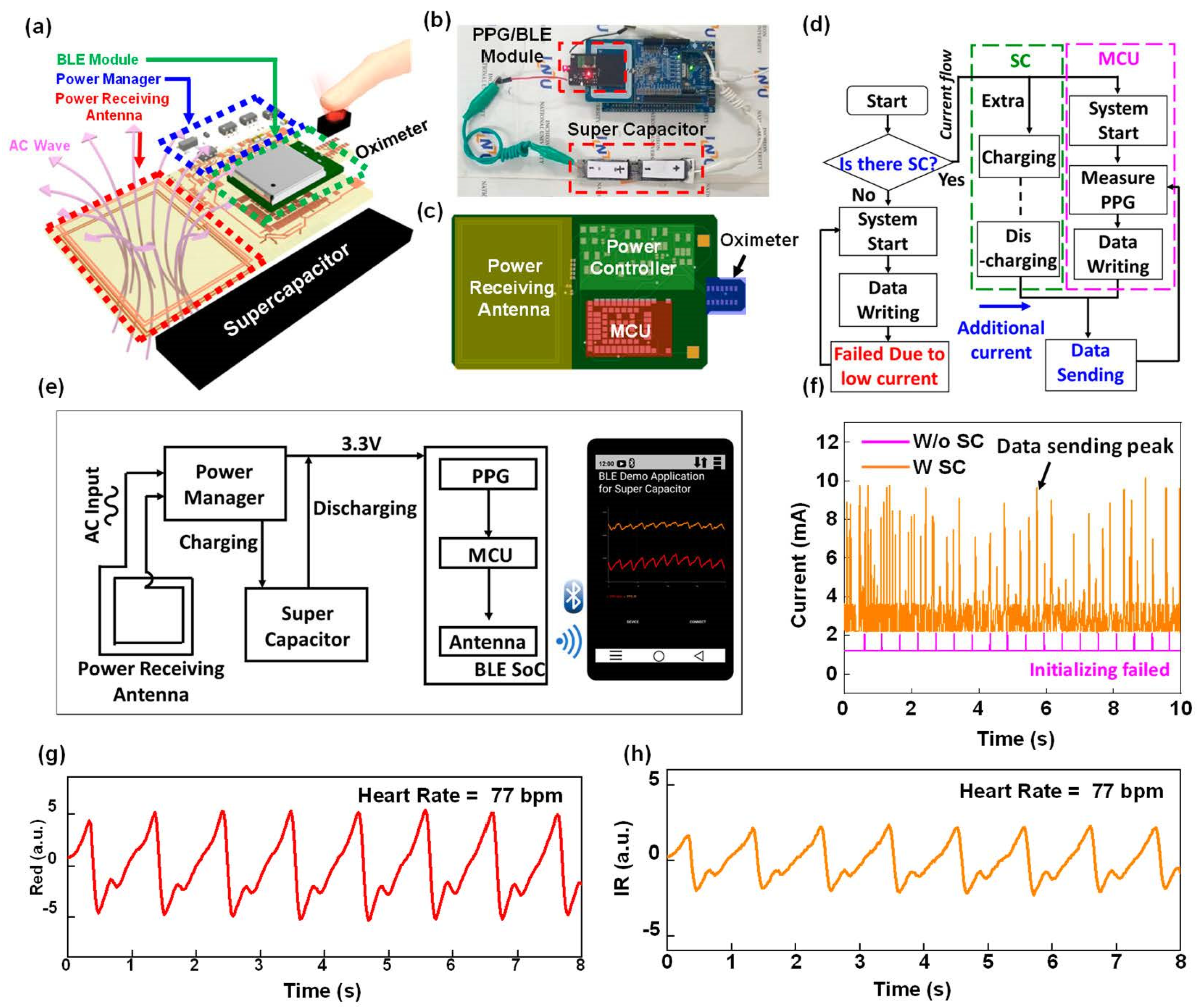
2.3. Design and Fabrication of Wireless Powered BLE/PPG Modules

Commercial PCB (printed circuit board) was used for the wireless powered BLE/PPG modules, which were designed by using Eagle CAD version 9 (AUTODESK) software. To assemble the device, surface mount type passive components (resistors, capacitors footprint 0201), BLE SoC (Bluetooth Low Energy System on a Chip) (NINA-B306, U-blox), and PPG (Photoplethysmogram) module (MAX30102, Maxim Integrated) were mounted on PCB with solder paste procured from SMDLTLFP, Chip Quik Inc. (Hamilton, ON, Canada). The detailed circuit connection is explained later.

2.4. Fabrication of ASC Device

For the fabrication of solid-state symmetric (SSC) devices, an electrode sample on an NF substrate with a deposition area of (2 × 3) cm2 was used as the electrode sample. A semisolid electrolyte gel was made by dissolving 3 g of PVA and 3 g of KOH in 30 mL of deionized water. With continuous stirring, this combination solution was heated to 90 degrees Celsius, resulting in the production of a translucent electrolyte gel. The prepared electrodes were soaked in electrolyte gel for two minutes and then sandwiched together using 0.45-micron filter paper (Millipore, Burlington, MA, USA) as a separator, which was kept at room temperature. The fabricated SSC device was well-covered with paraffin film to prevent leaking and short circuiting, and it was allowed to solidify at room temperature overnight to ensure proper operation. After assembling of electrodes soaked in gel electrolyte separated by the filter paper, the assembled SSC device was put under pressure to minimize the interfacial resistance. Lastly, the assembled SSC was tested after drying to avoid any short circuiting.

3. Results and Discussion

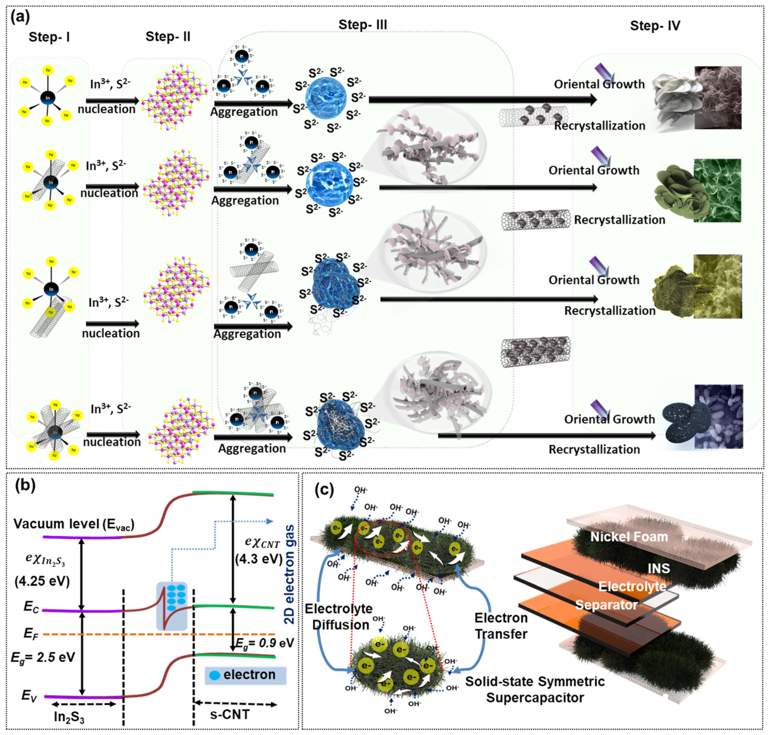
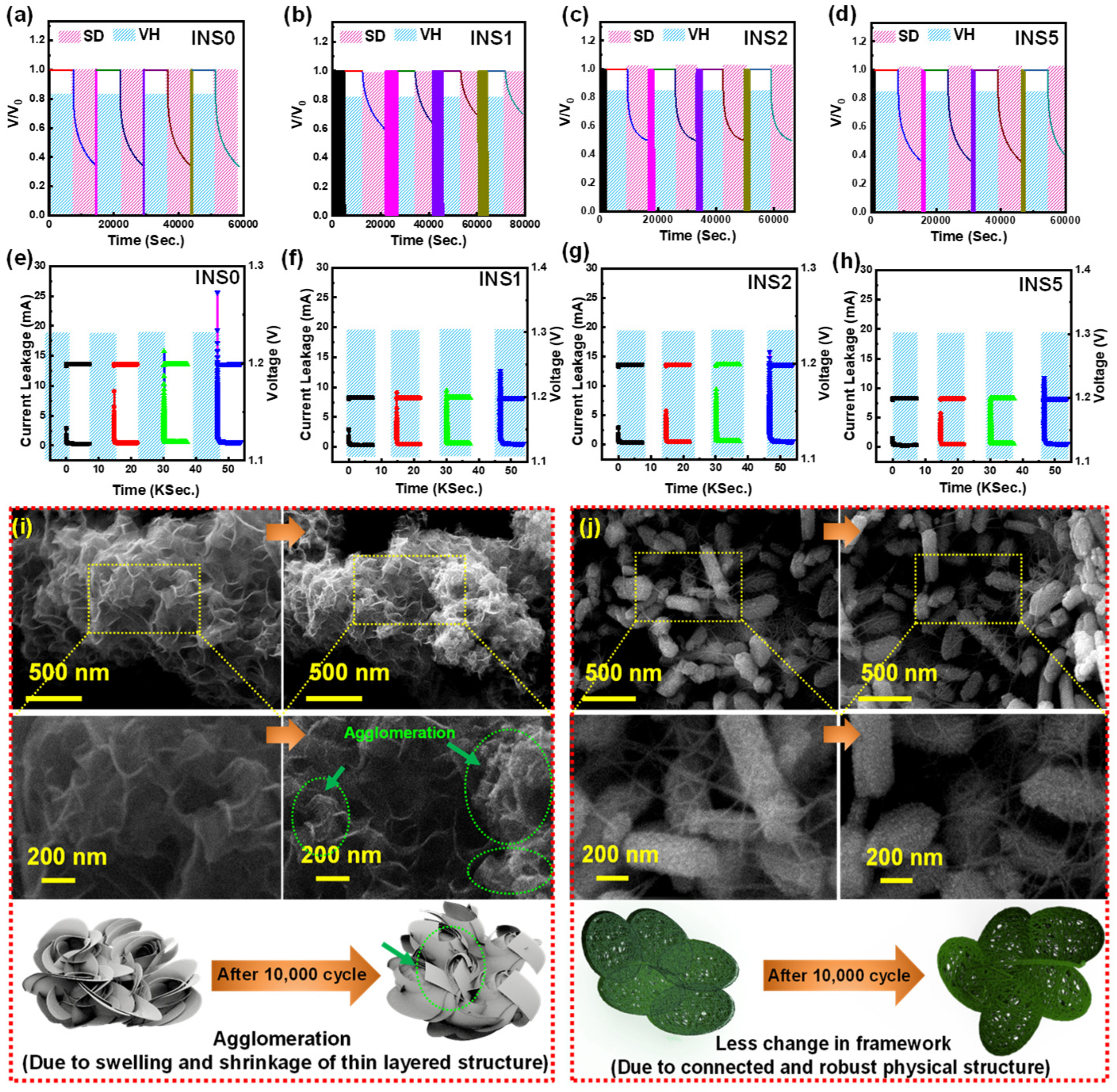
3.1. Morphological Evolution from Nanoflower to Cocoon-like Feature of INDIUM Sulfides and Their Growth Mechanism

Figure 1a represents a 3D schematic cartoon illustrating the plausible stepwise route traced in the formation of the layered as-prepared In2S3 electrode material. As per the experimental findings, a 3D flowerlike morphology was exhibited by the INS0 electrode sample. However, the flowerlike morphology evolved from a 3D flowerlike morphology to a cocoon-like shape for the INS1, INS2, and INS5 with the increasing concentration of SWNT. The common steps involved in the synthesis of the electrode material can be categorized in the following steps: Step 1. nucleation; Step 2. reaction process; Step 3. aggregation; and Step 4. recrystallization.
Firstly, the indium–TU complexes are formed owing to the rapid dissolution of reactants, which indicates the full coordination with In3+ and prevents the hydrolysis and precipitation of In3+ [26]. At the beginning of the reaction, highly supersaturated In2S3 associated with excessive S2− ions produces a large number of In2S3 nuclei, which leads to more In2S3 nanoparticles. Consequently, in the reaction step, the high-energy water molecules aggressively shake the S–C bond of TU, which releases the S2− ions associated with TU. This excess S2− tends to adhere to product surfaces due to the electrostatic interaction between S2− and In3+ and can be produced in the third step with the constant supply of building blocks. When the newly generated metal sulfur species are coupled, their charge density is reduced, leading to a stable cubic phase In2S3 nuclei with ion coordination patterns similar to those in the solution [27]. By reducing the surface energy and hydrogen bond interactions, large microspheres can be formed. The IPA–water system has readily available hydrogen bonds that can provide a sufficient interaction force to participate in the process.
nTU + InIn 3 + In TU 4 3 +   or   n = 4   or   6
In TU 4 3 +   or   In TU 6 3 + + 10 H 2 O InS 4 5   or   InS 6 9 + 10 CH 3 CONH 2 + 20 H +
InS 4 5 + InS 6 9 In 2 S 3 + 7 S 2
For the INS1 samples, a discrete and ultra-thin petal layered nanostructure is exhibited, where the catalytic effect of the SWNTs is responsible for the initiation of nucleation site reactions involving the SWNTs’ reaction rate initiation. On the other hand, the INS2 (cross-linked layered structure) and INS5 (SWNT anchored cocoon shape) electrode materials show a highly interconnected and covered SWNT backbone with a high degree of connectivity of sheaths assembled [28]. SWNTs serve as an excellent growing medium for the nucleation and growth of In2S3 into an interconnected layered structure [29,30]. The sheath-like structure of In2S3 in sample INS5 grew on the SWNT backbone and assembled in a connected cocoon shape with the covered SWNT net layer. As illustrated in Figure 1b, an electron gas in the second dimension was formed due to the energy band bending in the heterostructures. Increased electrochemical properties of the SSC device may be achieved by tuning the energy band diagram and forming the 2D electron gas. Figure 1c displays a schematic illustration of electrode fabrication and ion charge transportation through electrode material.

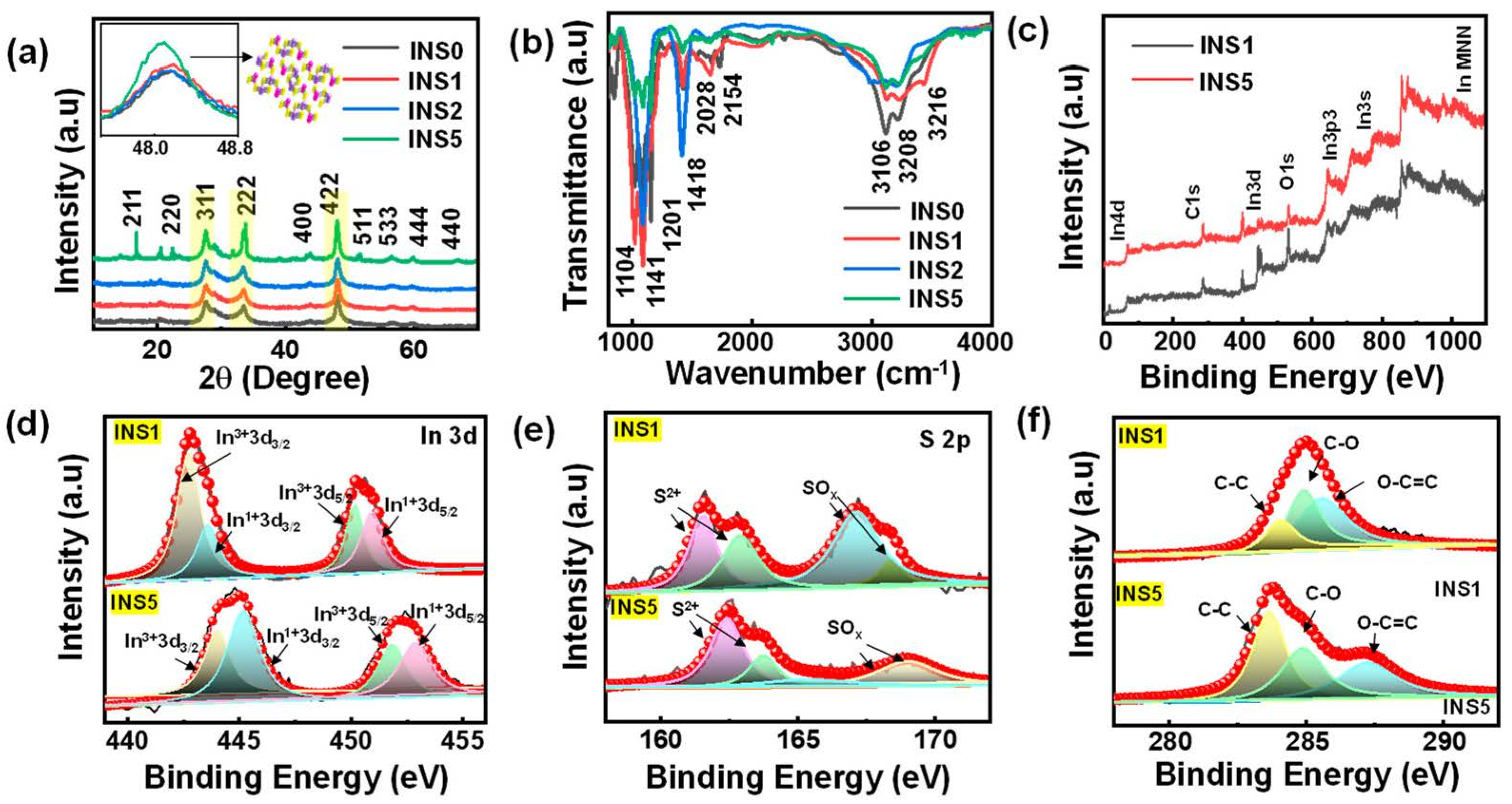
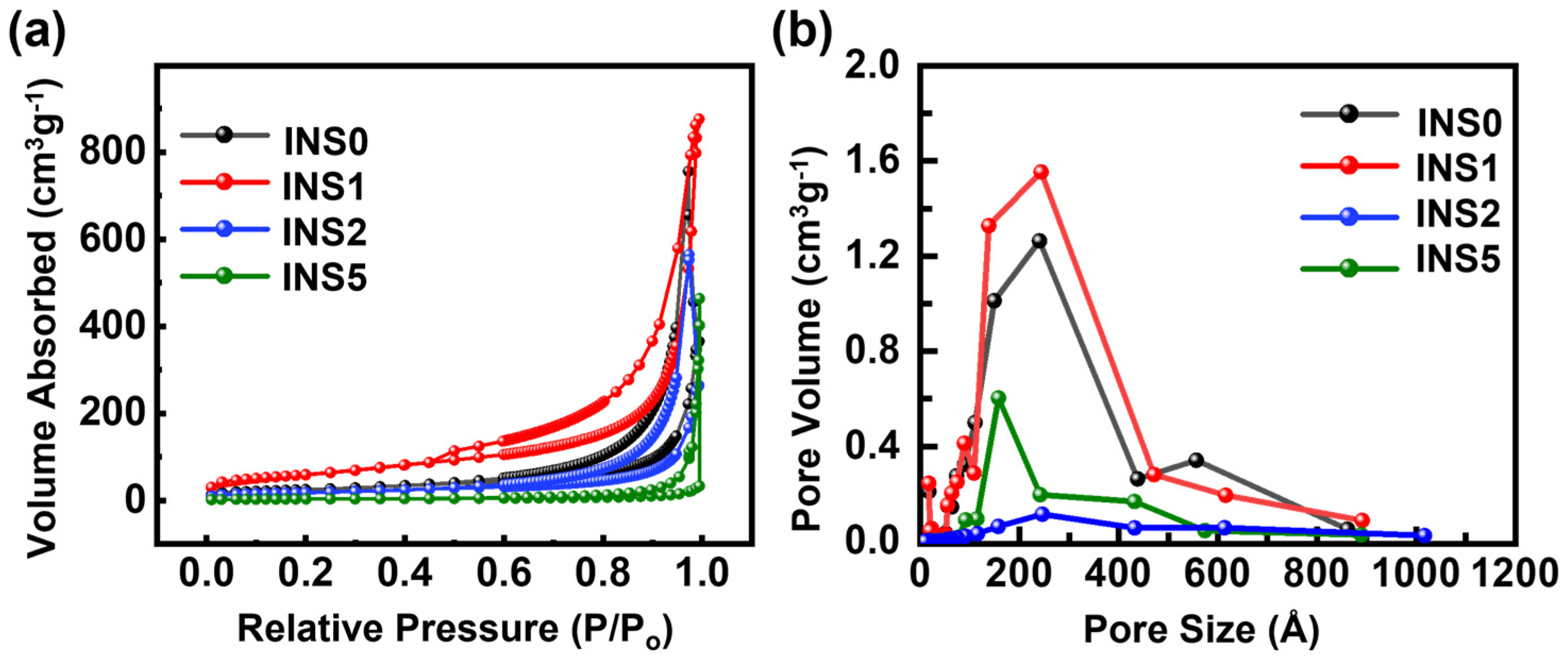
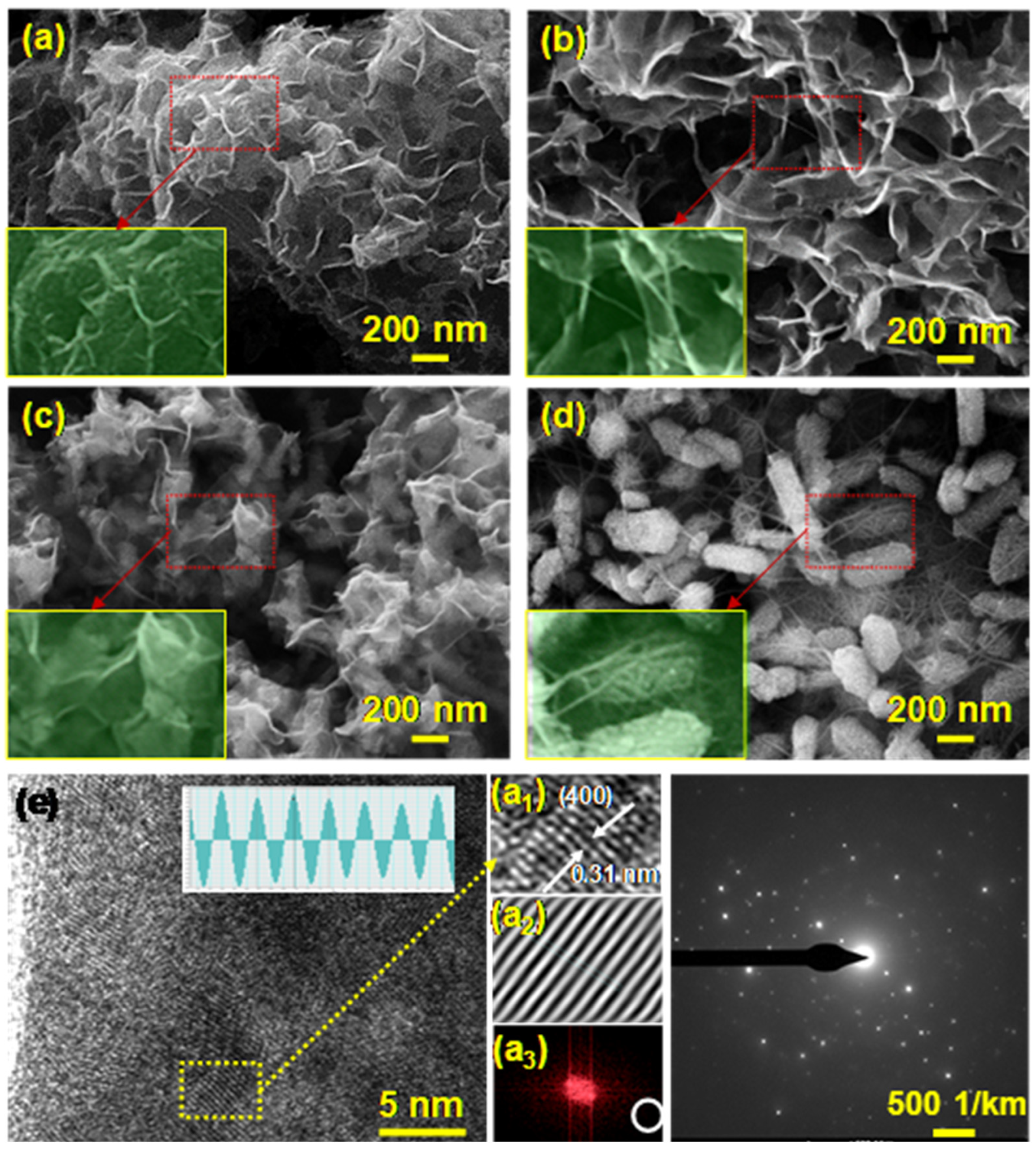
3.2. Structure and Morphology Studies

The crystallography and structural changes of the prepared materials were determined using XRD (X-ray diffraction) characterization. Figure 2a depicts a plot of the XRD patterns obtained from electrode samples. The ICDD Number 32-0456 is well-matched to the observed peak intensities, indicating that all samples are cubic phases of In2S3 [11]. These values are consistent with previously reported values and attributed to the cubic β phase In2S3 [31]. Clearly observed intense peaks at 16.77°, 22.28°, 27.55°, 33.88°, 43.81°, 48.13°, 51.65°, 56.58°, and 66.82° correspond to different lattice planes of (211), (220), (311), (222), (400), (422), (511), (533), (444), and (440), respectively. The SWNT introduces structural changes in the phase structure that can be seen in the XRD results as well as weaker diffraction peaks [7]. Furthermore, the addition of SWNTs at various weight ratios provides an active nucleation site for the growth of INS materials and an increase in the crystallinity of these materials [32]. The results showed that SWNTs could enhance the crystallization process of INS materials, which is in line with previous research [33].
Due to the low SWNT concentration in the nanocomposites, no SWNT peaks can be seen in the results. This is attributed to the main characteristic peak of SWNTs at 26.6°, which coincides with the (311) peak of cubic In2S3 at 27.2° in this case [34]. The average crystallite sizes of In2S3 and various SWNT addition ratios are summarized in Table 1. The Scherrer formula (D = 0.89λ/βcosθ) is used to calculate the average crystallite sizes of InS samples based on the (422) peak of the XRD patterns (inset of Figure 2a). Here λ is the wavelength (Cu Kα = 0.15406 nm), β is FWHM of the peak in radians, and θ is the corresponding diffraction angle [35]. The average crystallite sizes of InS nanocomposites are similar, implying that the addition of SWNTs to the matrix of In2S3 has no discernible impact on the crystallite sizes of In2S3 particles.
The Fourier-transform infrared (FTIR) spectrum of In2S3 was analyzed to determine its molecular structure and functional groups (Figure 2b). The O-H vibration mode of chemisorb water molecules corresponds to broad peaks near 3208 cm−1, the bend vibration mode of H2O corresponds to 1654 cm−1, and the sulfonic vibration mode corresponds to sharp peaks between 800 and 1500 cm−1 [11,36]. INS samples show a characteristic peak at 1418 cm−1, which corresponds to the typical bending vibrations of C=C or carbon skeleton vibrations of SWNTs, indicating the presence of SWNTs [37]. The characteristic bands at 1201 and 1141 cm−1 indicate the presence of the sulfonic group (SO3H) [29]. The sulfone group (SO2−) is associated with the band at 1103 cm−1. Furthermore, we used X-ray photoelectron spectra to verify the sample’s chemical composition and bonding state. The INS survey spectrum of samples INS1 and INS5 in Figure 2c reveals the presence of In, S, and C elements. The O 1s signal could be caused by a residue oxygen-containing group of adsorbed oxygen on the sample surface.
The formation of S-C bonds may be linked to the appearance of In3+. In Figure 2d, the In 3d spectra of the two compounds have comparable characteristics, with shifted peaks. Meanwhile, shifted peaks are observed in INS5, demonstrating the carbon existence on the substrate surface. The doublet peaks correspond to the In 2d3/2 and In 2d5/2 of INS1. The S2p spectra of INS samples are depicted in Figure 2b, and it has two prominent peaks that can be ascribed to S2− (161.5 and 162.7 eV) and SOx (167.1 and 168.5 eV). The SOx peaks could have been caused by adsorbed oxygen on the active surface of the INS samples [38]. The binding energies of the functional groups (C–C), (C–O), and (O–C=C), as determined by C1s XPS spectra, were found to be around 284, 285, and 286 eV, respectively. Using Barrett–Joyner–Halenda (BJH) analyses, N2 adsorption and desorption tests were conducted to characterize pore distribution and determine the sample’s surface area. The adsorption/desorption isotherms of all preparations display a hysteresis loop, indicating mesopores (Figure 3a). A hysteresis loop was discovered in the relative pressure range (P/Po) of 0.6 to 0.96, indicating the presence of isotherm mesopores of type IV [39]. The sample INS1 has a BET surface area of 216 m2g−1, as determined by the experiment. The sample INS1 had the highest quantified specific surface area value, further matched with its microstructures as determined by FESEM morphology. The large surface area and mesoporous structure of INS1 nanoparticles will help electrolyte ions move and diffuse, leading to the improved performance of supercapacitors [40]. INS with well-defined mesopores are good for ion transfer and electrochemical double layer formation. The larger pore size of the mesoporous materials improved the wettability of the electrodes, making the interstitials more likely to act as electrolyte reservoirs [41].
A Barrett–Joyner–Halenda (BJH) analysis was used to determine the distribution of pore sizes (Figure 3b), which showed the presence of macropores and mesopores in the sample [42]. The specific surface area and pore volume distribution curves of all prepared materials were calculated using the standard multi-point BET, which provides a comprehensive insight into the surface area, pore volume, and pore area distribution. The micropores and mesopores in the samples act as ion trapping sites and as electrolyte ion transport channels, allowing for efficient energy storage and delivery [43]. Furthermore, the surface morphology of the directly grown electrode materials was investigated by using FESEM. Figure 4a shows a two-dimensional interconnected nano-sponge-like layered structure for sample INS0. INS1 (Figure 4b) shows a separated layered structure, which is considered a desirable morphology for charge storage applications [44]. Ion access at material interfaces is greatly improved by the discrete, layered structure described above, which also helps achieve better capacitive properties by allowing for larger ion buffer reservoirs [45,46]. The catalytic effect of the SWNT accelerated the synthesis reaction and resulted in the formation of the In2S3-SWNT scramble structure. In sample INS1, a small amount of SWNT (1 mL) induces a nucleation site reaction, resulting in a separated layered structure. Incorporating a greater proportion of SWNTs allows for developing a novel cocoon-shaped morphology, which provides a robust framework for long-term stability. In2S3-SWNTs networks are capable of improving electrode performance due to their synergistic effect [47]. Sample INS2 (Figure 4c) shows a SWNT cross-linked layered structure, and sample INS5 (Figure 4d) shows a SWNT anchored cocoon shape. The distributed SWNT is clearly visible in samples INS2 (cross-linked structure) and INS5 (net-like structure). Interestingly, changes in the morphology with SWNT ratio suggest the kinetic and catalytic behavior of a SWNT in the layered structure morphology. The SWNT anchored framework in the INS5 sample provides a reinforcement structure, which provides a robust structure and suppresses the stacking of the layered base material to achieve long-term cyclic performance [45,48]. The in-situ participation of the SWNT during solvothermal synthesis provides a place for forming new layers in a SWNT network-based cocoon-shaped material, based on the amount of added SWNTs. A good discrete layered structure material (INS1) has a high effective surface area and shows a high specific capacitance. The cocoon-shaped structure (INS5) shows how a reinforced network can be used to make a strong structure that can withstand long cycles with some compromise of capacitance value. SWNTs’ integration in electrode material helps to move ions quickly, has a high surface area, and acts as a spacer for preventing layer stacking during the electrochemical reaction [25,34].
More importantly, the cocoon structure grows over and around itself, reducing shrinkage and expansion during ionic reactions for charge storage and enhancing cyclic behavior [49]. The HRTEM image of sample INS2 shown in Figure 4e shows the clearly visible atomic fringes. The atomic spacing in this high-resolution image is 0.31 nm, which corresponds to the XRD d-spacing index (400). The SAED pattern of the corresponding image indicates that the material is polycrystalline, and it matches with the XRD pattern. In Figure S1a,b, the layered structure of INS1 is demonstrated by dark field and bright field TEM images.

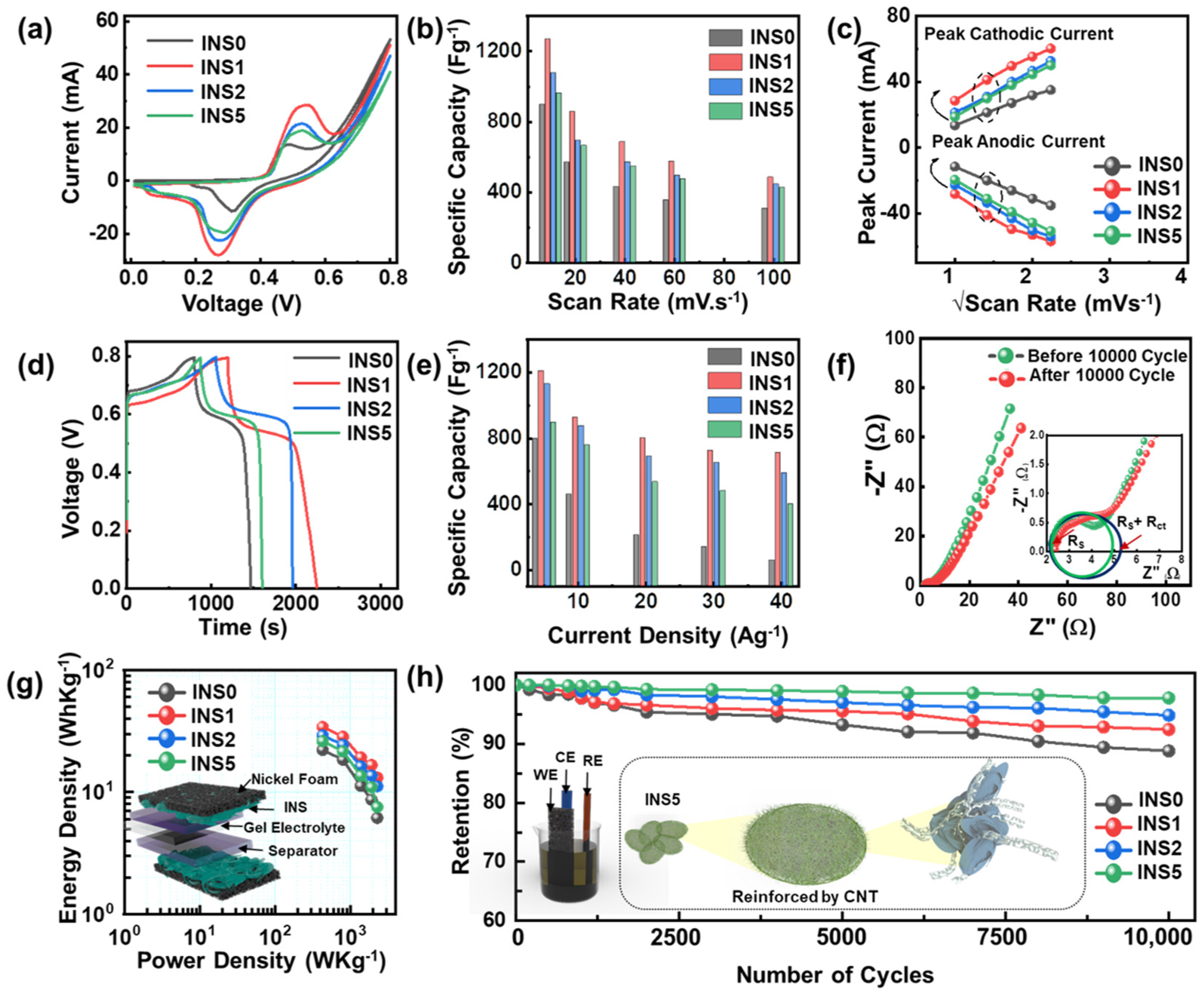
3.3. Electrochemical Studies

The electrochemical behavior of the as-prepared template-free electrode samples was studied via Cyclic Voltammetry (CV), galvanostatic charge–discharge (GCD), and electrochemical impedance spectroscopy (EIS). The CV spectra of the electrode materials INS0, INS1, INS2, and INS5 in three electrode systems at various scan rates are depicted in Figure 5a. All the sample electrode materials show reversible redox peaks in their 3T CV curves. The nonrectangular curve shape indicates the presence of pseudocapacitance [50]. The enclosed areas under the CV curve for the three samples are comparatively illustrated at 10 mVs−1. The sample, INS1, exhibits the highest curve area under the CV curve, leading to better charge storage capacity. Figure 5b depicts the calculated specific capacitance from the CV curve at various scan rates, ranging from 10 mVs−1 to 100 mVs−1 for all prepared electrode samples. At a scan rate of 10 mVs−1, the values of the specific capacitance for INS0, INS1, INS2, and INS5 are found to be 897 F·g−1, 1268 F·g−1, 1076 F·g−1, and 963 F·g−1, respectively. While at 100 mVs−1, the values of maintained specific capacitance are 306 F·g−1, 484 F·g−1, 444 F·g−1, and 425 F·g−1, respectively. More accessible electrochemical kinetics and a higher surface area in sample INS1 lead to a higher charge storage capacity [51]. The reversible redox reaction of the In2S3 ionic charge storage behavior with hydroxide counter anions (OH−1) in the electrolyte (KOH) can be expressed as follows:
In2S3 + OH ↔ In2S3OH + e
At all scan rates, the linear connection between the redox peak current and the scan rate (Figure 5c) indicates that the electrode surface reaction is diffusion-controlled [52]. Figure 5d depicts a comparative GCD curve for all the prepared electrode samples. Nonlinear GCD curves in all samples indicate that the electrode material exhibits obvious pseudocapacitive charge storage behavior [53]. Higher discharge times associated with INS1 suggest better charge storage capacity.
Figure 5e illustrates the specific capacitance plot against the current density’s values. The excellent capacitance value in the INS1 electrode is (i) due to an optimal layering structure, the layered facets of 2D In2S3 enable highly accessible interfacial contacts, leading to greater use of ion accumulation, and (ii) due to thin-layered interfaces, there is a reduction in internal material resistance, and the short electron diffusion length is associated with this phenomenon during the charge/discharge process [54,55]. The Nyquist plot was accomplished to understand better the frequency response and material charge transportation (Figure 5f). The semicircle intercept near the high-frequency region gives the series resistance (Rs), the semicircle radius gives an estimate of the charge transfer resistance (Rct), while Cp and W indicate the pseudocapacitance value and Warburg resistance, respectively, which are estimated from the line inclination in the low-frequency region [14]. Table 2 shows the Nyquist plot fitting equivalent impedance parameters before and after 10,000 cycles at a frequency range of 100 kHz to 0.01 Hz at 0.1 bias voltage. Even after a huge 10,000 GCD cycling, it shows an almost similar impedance parameter, which illustrates the better mechanical stability and non-degradation of the INS-based electrode materials. Furthermore, the Ragone plot (Figure 5g) estimates the operational and practical utility of the as-prepared electrode samples. The high-power density is a measure of faster charging, while the energy density measures the amount of energy that can be stored in the electrode.
This clearly gives an idea for estimating the form factor of the SSC device for a particular application. The sample INS5 has a decent energy density of 26 Whkg−1 at a power density of 431 Wkg−1. Lastly, the long-term stability was evaluated by GCD cycling up to 10,000 cycles (Figure 5h), which showed that the electrode material INS5 maintained 97.79% of its starting capacity (significantly higher than bare INS0-82.44% and higher than sample INS1-88.81%), proving its excellent long-term endurance. The inset in Figure 5h shows a schematic of an INS5 robust structure with SWNT integration to provide reinforcement and keep the structure stable in the face of electrochemical reactions, resulting in high endurance. The inset of Figure 5h shows how the SWNT reinforces the INS5 electrode material, which leads to a robust nanostructure and ensures long-term stability.
Another important performance factor to consider when evaluating the suitability of SCs for potential implementation is their self-discharge (SD) behavior, and voltage-holding (VH) capability. The loss of the charged potential without any load at OCP (open circuit potential) is referred to as the SD of an SC. However, VH refers to the ability to maintain a constant voltage for a specified period. The current leakage in INSC is evaluated at the VH test. For all prepared SSC devices from samples INS0, INS1, INS2, and INS5, Figure 6a–d show four continuous cycle measurements of GCD (100 cycles), followed by a 2 h VH test, and thereafter, an SD test for all fabricated SSC devices. For each cycle, the GCD cycle was performed at 1 Ag−1 in the potential window ranging from 0 to 1.0, while the VH test was performed for 2 h at constant supply 1.0 V, and the SD test was performed at OCP (no potential). The leakage current measured during the voltage holding test is critical in determining the fabrication errors in the device [56]. The leakage current of an SSC is caused by irreversible side reactions between the electrodes and electrolytes directly related to the device architecture. The leakage current value is preferably less because the high value indicates that the separator has shorted the connection between the two electrodes [57]. The leakage current (Figure 6e–h) drops abruptly in the range of 5–25 µA in this measurement, which occurs at the start of the 1.2 V holding test. It gradually shifts into the constant mode for the 2 h VH test duration. A four-cycle VH test, performed continuously over a period of two hours, reveals virtually no internal resistance under device-level performance [58]. Following the VH mode, the self-discharge test was completed in the OCP mode. The SD of the SC device is directly related to the Faradic charge reaction as well as the resistance/diffusion charge redistribution [59]. After four consecutive cycles of the voltage holding procedure, the leakage currents of the INS1 (60 μA, 42 μA, 38 μA, 37 μA) indicate that there was no formation of internal resistance during the voltage-holding procedure. At OCP, the self-discharging (SD) of INS-based devices decreased gradually from 1.0 V to 0.8 V, whereas the SC devices remained stable at 0.8 V. Correspondingly, the self-discharge mechanism is related to how the SSC cell behaves as it self-discharges after being charged to a specific potential [42,60].
Active-controlled Faradaic reactions, resistance-limited redistribution, and diffusion-limited redistribution of charge are all potential outcomes, as are activated-controlled faradaic processes and charge redistribution alone [57]. The self-discharge must be repeated several times for the activation control model to be valid [59]. Another possibility is that other mechanisms are involved in the charge transmission process, as indicated by the variation in self-discharge. It followed the same path for four successive charge–discharge cycles, the voltage holds, and self-discharges. Samples from INS0 to INS5 were tested for SD, VH, and leakage currents, denoting that SD mitigation was attributable to an increase in nanostructural integrity. Figure 6i,j show the morphology demonstration of samples INS0 and INS5 before and after 10,000 cycle stability tests. In order to aid in comprehension, structural change is indicated in the scheme in both illustrations. After 10,000 cycles, the petal structure of sample INS0 is lumped and aggregated. Furthermore, the granules can still be seen in the image taken after the cycle in Figure 6i. In INS5 (which shows some swelling in the structure), there is no significant difference, indicating improved material physical structure stability. Structural stability is extremely high for the reinforced structure represented in Figure 6j.
Table 3 shows that the cyclic stability and capacitance values of our work are higher/comparable to those of several indium-based electrode materials that were previously reported. The developed SSC device was demonstrated to be capable of providing additional power for wireless communication to validate its practical application. Supplied power from WPT was used for the SSC charging and PPG/BLE module operation, respectively. In this instance, it allows for the realization of a fully battery-free system.
Figure 7a depicts a schematic cartoon of the wireless powered BLE/PPG module including the SSC. Typically, wearable devices for health care are designed as two-part, (1) measuring biosignals with low power consumption; (2) sending data to other platforms (e.g., smartphone, desktop, server) with momentary high-power consumption [71,72,73]. The wireless powered system with temporary energy storage such as SCs is preferable for the health care devices rather than chemical batteries because of its long-lasting potential safety and maintenance issue. The device efficiency is further improved by using a simple domestic vacuum sealing method, making it suitable for long-term environmental stability.
The wireless powered BLE/PPG module includes four different parts, (1) a power receiving antenna, (2) a power controller for voltage regulation, (3) a micro control unit (MCU) for Bluetooth communication, and (4) an oximeter for measuring the biosignal (Figure 7b). After connecting the SSCs to the wireless powered BLE/PPG module, the device was placed on the NFC-based wireless power transmitter (nRF52-DK with Radio Frequency Dev Kit, Nordic Semiconductor and STMicroelectronics, respectively) to supply wireless power, as shown in Figure 7c. An integrated system was the most effective option when the wireless devices required momentary higher power than the supplied power for sending data to other wireless devices. Figure 7d shows the current flow of the wireless powered BLE/PPG module with (and without) a supercapacitor. Without a supercapacitor, the system operation failed when sending data due to low supplied power. On the other side, the system shows stable operation without fail with a supercapacitor. A supercapacitor can store the energy with extra power while measuring biosignals. Moreover, the supercapacitor provides momentary high power while sending data via Bluetooth as temporary energy storage. Figure 7d shows a circuit diagram regarding the connection between the wireless powered module and SSC. A 5 V output pin from the power controller was connected to two input pins, (1) an anode pin of SSC for charging when the consumption power of the BLE/PPG module was less than the supplied power, and (2) the input of a 3.3 V voltage regulator for discharging to supplement the insufficient power while sending data via Bluetooth. The current consumption property of the wireless powered BLE/PPG module with (and without) a supercapacitor is shown in Figure 7f. The device without SSC failed in operation as it failed to initialize due to the lack of high power required during the initialization. However, SSC-connected devices utilized the excess power for SSC charging and facilitated the high power for the system initialization by discharging in burst mode. Such results shows that SSC provided energy effectively to the BLE/PPG module, and it is one of the best options for a wireless powered system to stabilize power consumption. Figure 7g,h show measured pulse signals from the oximeter placed on the index finger with red and IR LEDs. Each of the data from the two wavelengths have a different amplitude due to the dependency of the molar extinction coefficient spectra of the HbO2 and Hb solutions [74,75], (Figure S8) but shows the same heart rate (77 bpm). In this sense, the SSC can be a better option than the battery for a wireless powered system. All capacitive and practical performances indicate that the novel electrode materials that were prepared have tremendous potential in future energy storage applications.

4. Conclusions

The study presented in this work successfully synthesized uniform and well-separated 2D In2S3 nanoflakes through a facile solvothermal method. The sponge-like In2S3 nanoflake electrode produced demonstrated high capacitance, excellent cyclic retention value, and a decent power density. The incorporation of SWNTs in the 2D In2S3 nanoflakes significantly enhanced the cyclic retention of electrons, showcasing the potential of tailoring the SWNT-In2S3 heterostructure for superior electrodes. These findings provide evidence that 2D layered In2S3 electrode materials have promising electrochemical properties, making them a potentially promising next-generation electrode material for supercapacitor applications. Furthermore, the demonstration of the wireless power BLE/PPG module highlights the potential for a wirelessly powered sealed SSC device to act as an efficient battery substitute in wireless health monitoring systems. This study suggests that integrating 2D layered In2S3 electrode materials into SSC devices could result in high-performance supercapacitors that are suitable for use in a wide range of applications, including wireless health monitoring systems.
Overall, this work represents a significant contribution to the field of electrode material synthesis and provides a foundation for further research into the potential applications of 2D layered In2S3 electrode materials. It is speculated that this research will inspire future studies to explore the full potential of these materials for energy storage and other applications, leading to the development of more efficient and sustainable energy technologies.

Supplementary Materials

The following supporting information can be downloaded at: https://www.mdpi.com/article/10.3390/app13052958/s1, Figure S1: Full scan XPS spectra of INS1 sample; Figure S2: Bright TEM field image (a) HAADF TEM image, (b) of INS1 electrode sample; Figure S3: Color mapping image of INS0, INS1, INS2, and INS5 samples; Figure S4: EDAX spectra of INS0, INS1, INS2, and INS5 samples; Figure S5: 3T CV curves of (a) INS0, (b) INS1, (c) INS2, and (d) INS5 samples; Figure S6: 3T terminal GCD curves of (a) INS0, (b) INS1, (c) INS2, and (d) INS5 samples; Figure S7: 2T CV curves at (a) higher scan rates (10 mVs−1 to 100 mVs−1) of sample INS0, (b) at scan rate (1 mVs−1 to 5 mVs−1) for INS1, (c) comparative CV spectra of INS0 and INS1 (d) CV curve at different potential window of fabricated SSC device; Figure S8: Leakage current spectra of all prepared samples.

Author Contributions

Conceptualization, N.K., D.M. and S.H.J.; methodology, N.K. and K.M.; software, S.K., D.M. and K.M.; validation, D.M., R.K.M. and S.H.J.; formal analysis, N.K.; investigation, K.M.; resources, J.S. and S.H.J.; data curation, N.K. and D.M.; writing—original draft preparation, N.K. and D.M.; writing—review and editing, D.M. and S.H.J.; visualization, D.M.; supervision, R.K.M., J.S. and S.H.J.; project administration, J.S. and S.H.J.; funding acquisition, J.S. and S.H.J. All authors have read and agreed to the published version of the manuscript.

Funding

This research was funded by Post-Doctor Research Program (2018) through Incheon National University (INU), Incheon, Republic of Korea.

Data Availability Statement

No new data were created.

Conflicts of Interest

The authors declare no conflict of interest.

References

  1. An, C.; Zhang, Y.; Guo, H.; Wang, Y. Metal Oxide-Based Supercapacitors: Progress and Prospectives. Nanoscale Adv. 2019, 1, 4644–4658. [Google Scholar] [CrossRef] [PubMed] [Green Version]
  2. Wang, F.; Wu, X.; Yuan, X.; Liu, Z.; Zhang, Y.; Fu, L.; Zhu, Y.; Zhou, Q.; Wu, Y.; Huang, W. Latest Advances in Supercapacitors: From New Electrode Materials to Novel Device Designs. Chem. Soc. Rev. 2017, 46, 6816–6854. [Google Scholar] [CrossRef] [PubMed]
  3. Hou, W.; Sun, Y.; Zhang, Y.; Wang, T.; Wu, L.; Du, Y.; Zhong, W. Mixed-Dimensional Heterostructure of Few-Layer MXene Based Vertical Aligned MoS2 Nanosheets for Enhanced Supercapacitor Performance. J. Alloys Compd. 2021, 859, 157797. [Google Scholar] [CrossRef]
  4. Liu, Y.; Peng, X. Recent Advances of Supercapacitors Based on Two-Dimensional Materials. Appl. Mater. Today 2017, 8, 104–115. [Google Scholar] [CrossRef]
  5. Li, L.; Pandey, A.; Werder, D.J.; Khanal, B.P.; Pietryga, J.M.; Klimov, V.I. Efficient Synthesis of Highly Luminescent Copper Indium Sulfide-Based Core/Shell Nanocrystals with Surprisingly Long-Lived Emission. J. Am. Chem. Soc. 2011, 133, 1176–1179. [Google Scholar] [CrossRef]
  6. Acharya, S.; Sarkar, S.; Pradhan, N. Subnanometer Thin β-Indium Sulfide Nanosheets. J. Phys. Chem. Lett. 2012, 3, 3812–3817. [Google Scholar] [CrossRef]
  7. Miao, Y.F.; Guo, R.T.; Gu, J.W.; Liu, Y.Z.; Wu, G.L.; Duan, C.P.; Zhang, X.D.; Pan, W.G. Fabrication of β-In2S3/NiAl-LDH Heterojunction Photocatalyst with Enhanced Separation of Charge Carriers for Efficient CO2 Photocatalytic Reduction. Appl. Surf. Sci. 2020, 527, 146792. [Google Scholar] [CrossRef]
  8. Esmaili, P.; Kangarlou, H.; Savaloni, H.; Ghorannevis, M. Structural, Optical and Electronic Properties of Indium Sulfide Compositions under Influence of Copper Impurity Produced by Chemical Method. Results Phys. 2017, 7, 3380–3389. [Google Scholar] [CrossRef]
  9. He, Z.; Wang, Y.; Dong, X.; Zheng, N.; Ma, H.; Zhang, X. Indium Sulfide Nanotubes with Sulfur Vacancies as an Efficient Photocatalyst for Nitrogen Fixation. RSC Adv. 2019, 9, 21646–21652. [Google Scholar] [CrossRef] [Green Version]
  10. Zhao, X.; Mao, L.; Cheng, Q.; Li, J.; Liao, F.; Yang, G.; Xie, L.; Zhao, C.; Chen, L. Two-Dimensional Spinel Structured Co-Based Materials for High Performance Supercapacitors: A Critical Review. Chem. Eng. J. 2020, 387, 124081. [Google Scholar] [CrossRef]
  11. Kumar, N.; Mishra, D.; Yeob Kim, S.; Na, T.; Hun Jin, S. Two Dimensional, Sponge-like In2S3 Nanoflakes Aligned on Nickel Foam via One-Pot Solvothermal Growth and Their Application toward High Performance Supercapacitors. Mater. Lett. 2020, 279, 128467. [Google Scholar] [CrossRef]
  12. Kim, D.W.; Jung, S.M.; Jung, H.Y. Long Term Thermostable Supercapacitor Using In-Situ SnO2 Doped Porous Graphene Aerogel. J. Power Sources 2020, 448, 227422. [Google Scholar] [CrossRef]
  13. Laheäär, A.; Arenillas, A.; Béguin, F. Change of Self-Discharge Mechanism as a Fast Tool for Estimating Long-Term Stability of Ionic Liquid Based Supercapacitors. J. Power Sources 2018, 396, 220–229. [Google Scholar] [CrossRef]
  14. Kumar, N.; Sahoo, P.K.; Panda, H.S. Tuning the Electro-Chemical Properties by Selectively Substituting Transition Metals on Carbon in Ni/Co Oxide-Carbon Composite Electrodes for Supercapacitor Devices. New J. Chem. 2017, 41, 3562–3573. [Google Scholar] [CrossRef]
  15. Huang, W.; Song, M.; Zhang, Y.; Zhao, Y.; Hou, H.; Hoang, L.H.; Chen, X. Defects-Induced Oxidation of Two-Dimensional β-In2S3 and Its Optoelectronic Properties. Opt. Mater. 2021, 119, 111372. [Google Scholar] [CrossRef]
  16. Kennell, G.F.; Evitts, R.W. Two-Dimensional Lithium-Ion Battery Modeling with Electrolyte and Cathode Extensions. Adv. Chem. Eng. Sci. 2012, 02, 423–434. [Google Scholar] [CrossRef] [Green Version]
  17. Larsson, F.; Andersson, P.; Mellander, B.E. Lithium-Ion Battery Aspects on Fires in Electrified Vehicles on the Basis of Experimental Abuse Tests. Batteries 2016, 2, 9. [Google Scholar] [CrossRef]
  18. Loveridge, M.J.; Remy, G.; Kourra, N.; Genieser, R.; Barai, A.; Lain, M.J.; Guo, Y.; Amor-Segan, M.; Williams, M.A.; Amietszajew, T.; et al. Looking Deeper into the Galaxy (Note 7). Batteries 2018, 4, 3. [Google Scholar] [CrossRef] [Green Version]
  19. Hess, S.; Wohlfahrt-Mehrens, M.; Wachtler, M. Flammability of Li-Ion Battery Electrolytes: Flash Point and Self-Extinguishing Time Measurements. J. Electrochem. Soc. 2015, 162, A3084–A3097. [Google Scholar] [CrossRef]
  20. Elahi, A.; Amin, A.A.; Shami, U.T.; Usman, M.T.; Iqbal, M.S. Efficient Wireless Charging System for Supercapacitor-Based Electric Vehicle Using Inductive Coupling Power Transfer Technique. Adv. Mech. Eng. 2019, 11, 1–10. [Google Scholar] [CrossRef]
  21. Azad, A.; Pantic, Z. A Supercapacitor-Based Converter Topology for Grid-Side Power Management in Dynamic Wireless Charging Systems. In Proceedings of the ITEC 2019—2019 IEEE Transportation Electrification Conference and Expo, Detroit, MI, USA, 19–21 June 2019. [Google Scholar] [CrossRef]
  22. Simjee, F.I.; Chou, P.H. Efficient Charging of Supercapacitors for Extended Lifetime of Wireless Sensor Nodes. IEEE Trans. Power Electron. 2008, 23, 1526–1536. [Google Scholar] [CrossRef]
  23. Gao, C.; Huang, J.; Xiao, Y.; Zhang, G.; Dai, C.; Li, Z.; Zhao, Y.; Jiang, L.; Qu, L. A Seamlessly Integrated Device of Micro-Supercapacitor and Wireless Charging with Ultrahigh Energy Density and Capacitance. Nat. Commun. 2021, 12, 2647. [Google Scholar] [CrossRef] [PubMed]
  24. Aqueveque, P.; Barboza, J. Wireless Power System for Charge Supercapacitors as Power Sources for Implantable Devices. In Proceedings of the IEEE WoW 2015—IEEE PELS Workshop on Emerging Technologies: Wireless Power, Daejeon, Republic of Korea, 5–6 June 2015; pp. 3–7. [Google Scholar] [CrossRef]
  25. Wei, C.; Guo, W.; Yang, J.; Fan, H.; Zhang, J.; Zheng, W. Facile Solvothermal Synthesis of 3D Flowerlike β-In2S3 Microspheres and Their Photocatalytic Activity Performance. RSC Adv. 2014, 4, 50456–50463. [Google Scholar] [CrossRef]
  26. Zhou, J.; Tian, G.; Chen, Y.; Shi, Y.; Tian, C.; Pan, K.; Fu, H. Growth Rate Controlled Synthesis of Hierarchical Bi2S 3/In2S3 Core/Shell Microspheres with Enhanced Photocatalytic Activity. Sci. Rep. 2014, 4, 4027. [Google Scholar] [CrossRef] [PubMed] [Green Version]
  27. Ma, F.; Yuan, A.; Xu, J.; Hu, P. Porous α-MoO3/MWCNT Nanocomposite Synthesized via a Surfactant-Assisted Solvothermal Route as a Lithium-Ion-Battery High-Capacity Anode Material with Excellent Rate Capability and Cyclability. ACS Appl. Mater. Interfaces 2015, 7, 15531–15541. [Google Scholar] [CrossRef] [PubMed]
  28. Zhou, H.; Zhang, L.; Zhang, D.; Chen, S.; Coxon, P.R.; He, X.; Coto, M.; Kim, H.K.; Xi, K.; Ding, S. A Universal Synthetic Route to Carbon Nanotube/Transition Metal Oxide Nano-Composites for Lithium Ion Batteries and Electrochemical Capacitors. Sci. Rep. 2016, 6, 37752. [Google Scholar] [CrossRef] [Green Version]
  29. Wu, H.; Guo, J.; Yang, D. Facile Autoreduction Synthesis of Core-Shell Bi-Bi2O3/CNT with 3-Dimensional Neural Network Structure for High-Rate Performance Supercapacitor. J. Mater. Sci. Technol. 2020, 47, 169–176. [Google Scholar] [CrossRef]
  30. Yu, Z.; Huang, L.; Chen, J.; Tang, Y.; Xia, B.; Tang, D. Full-Spectrum Responsive Photoelectrochemical Immunoassay Based on β-In2S3@carbon Dot Nanoflowers. Electrochim. Acta 2020, 332, 135473. [Google Scholar] [CrossRef]
  31. Prabakaran, K.; Ingavale, S.B.; Kakade, B. Three Dimensional NiS2–Ni(OH)2/CNT Nanostructured Assembly for Supercapacitor and Oxygen Evolution Reaction. J. Alloys Compd. 2020, 812, 152126. [Google Scholar] [CrossRef]
  32. Jian, S.L.; Hsiao, L.Y.; Yeh, M.H.; Ho, K.C. Designing a Carbon Nanotubes-Interconnected ZIF-Derived Cobalt Sulfide Hybrid Nanocage for Supercapacitors. J. Mater. Chem. A 2019, 7, 1479–1490. [Google Scholar] [CrossRef]
  33. Yang, M.Q.; Weng, B.; Xu, Y.J. Synthesis of In2S3-CNT Nanocomposites for Selective Reduction under Visible Light. J. Mater. Chem. A 2014, 2, 1710–1720. [Google Scholar] [CrossRef]
  34. Peng, D.; Zhang, Y.; Xu, G.; Tian, Y.; Ma, D.; Zhang, Y. Novel p–n Heterojunctions Incorporating NiS1.03@C with Nitrogen Doped TiO2 for Enhancing Visible-Light Photocatalytic Performance towards Cyclohexane Oxidation. Appl. Surf. Sci. 2021, 566, 150676. [Google Scholar] [CrossRef]
  35. Gao, W.; Liu, W.; Leng, Y.; Wang, X.; Wang, X.; Hu, B.; Yu, D.; Sang, Y.; Liu, H. In2S3 Nanomaterial as a Broadband Spectrum Photocatalyst to Display Significant Activity. Appl. Catal. B Environ. 2015, 176–177, 83–90. [Google Scholar] [CrossRef]
  36. Li, Y.; Song, C.; Chen, J.; Shang, X.; Chen, J.; Li, Y.; Huang, M.; Meng, F. Sulfur and Nitrogen Co-Doped Activated CoFe2O4@C Nanotubes as an Efficient Material for Supercapacitor Applications. Carbon 2020, 162, 124–135. [Google Scholar] [CrossRef]
  37. Chen, H.; Wang, M.Q.; Yu, Y.; Liu, H.; Lu, S.Y.; Bao, S.J.; Xu, M. Assembling Hollow Cobalt Sulfide Nanocages Array on Graphene-like Manganese Dioxide Nanosheets for Superior Electrochemical Capacitors. ACS Appl. Mater. Interfaces 2017, 9, 35040–35047. [Google Scholar] [CrossRef]
  38. Mishra, D.; Kim, S.; Kumar, N.; Krishnaiah, M.; Jin, S.H. Self-Discharge Mitigated Supercapacitors via Hybrid CuO-Nickel Sulfide Heterostructure for Energy Efficient, Wireless Data Storage Application. J. Mater. Sci. Technol. 2023, 147, 77–90. [Google Scholar] [CrossRef]
  39. Chang, Y.; Sun, X.; Ma, M.; Mu, C.; Li, P.; Li, L.; Li, M.; Nie, A.; Xiang, J.; Zhao, Z.; et al. Application of Hard Ceramic Materials B4C in Energy Storage: Design B4C@C Core-Shell Nanoparticles as Electrodes for Flexible All-Solid-State Micro-Supercapacitors with Ultrahigh Cyclability. Nano Energy 2020, 75, 104947. [Google Scholar] [CrossRef]
  40. Qiu, Y.; Hou, M.; Gao, J.; Zhai, H.; Liu, H.; Jin, M.; Liu, X.; Lai, L. One-Step Synthesis of Monodispersed Mesoporous Carbon Nanospheres for High-Performance Flexible Quasi-Solid-State Micro-Supercapacitors. Small 2019, 15, 1903836. [Google Scholar] [CrossRef] [PubMed]
  41. Ochai-Ejeh, F.O.; Madito, M.J.; Momodu, D.Y.; Khaleed, A.A.; Olaniyan, O.; Manyala, N. High Performance Hybrid Supercapacitor Device Based on Cobalt Manganese Layered Double Hydroxide and Activated Carbon Derived from Cork (Quercus Suber). Electrochim. Acta 2017, 252, 41–54. [Google Scholar] [CrossRef] [Green Version]
  42. Kumar, R.; Agrawal, A.; Bhuvana, T.; Sharma, A. Porous Indium Oxide Hollow Spheres (PIOHS) for Asymmetric Electrochemical Supercapacitor with Excellent Cycling Stability. Electrochim. Acta 2018, 270, 87–95. [Google Scholar] [CrossRef]
  43. Zhai, Z.; Yan, W.; Dong, L.; Wang, J.; Chen, C.; Lian, J.; Wang, X.; Xia, D.; Zhang, J. Multi-Dimensional Materials with Layered Structures for Supercapacitors: Advanced Synthesis, Supercapacitor Performance and Functional Mechanism. Nano Energy 2020, 78, 105193. [Google Scholar] [CrossRef]
  44. Liu, X.; Zhou, A.; Pan, T.; Dou, Y.; Shao, M.; Han, J.; Wei, M. Ultrahigh-Rate-Capability of a Layered Double Hydroxide Supercapacitor Based on a Self-Generated Electrolyte Reservoir. J. Mater. Chem. A 2016, 4, 8421–8427. [Google Scholar] [CrossRef]
  45. Lai, C.; Sun, Y.; Zhang, X.; Yang, H.; Kang, W.; Lin, B. Advanced Flower-like Co3O4 with Ultrathin Nanosheets and 3D RGO Aerogels as Double Ion-Buffering Reservoirs for Asymmetric Supercapacitors. Electrochim. Acta 2018, 271, 379–387. [Google Scholar] [CrossRef]
  46. Ye, J.; Hu, B.; Jin, Y.; Wang, Z.; Xi, Y.; Fang, L.; Pan, Q. Interface Engineering Integrates Fractal-Tree Structured Nitrogen-Doped Graphene/Carbon Nanotubes for Supercapacitors. Electrochim. Acta 2020, 349, 136372. [Google Scholar] [CrossRef]
  47. Shi, P.; Li, L.; Hua, L.; Qian, Q.; Wang, P.; Zhou, J.; Sun, G.; Huang, W. Design of Amorphous Manganese Oxide@Multiwalled Carbon Nanotube Fiber for Robust Solid-State Supercapacitor. ACS Nano 2017, 11, 444–452. [Google Scholar] [CrossRef]
  48. Seo, S.G.; Baek, J.I.; Mishra, D.; Jo, H.; Kwon, H.-I.; Jin, S.H. One-Pot Hydrothermal Growth of Indium Oxide-CNT Heterostructure via Single Walled Carbon Nanotube Scaffolds and Their Application toward Flexible NO2 Gas Sensors. J. Alloys Compd. 2022, 922, 166169. [Google Scholar] [CrossRef]
  49. Sun, J.; Iakunkov, A.; Rebrikova, A.T.; Talyzin, A.V. Exactly Matched Pore Size for the Intercalation of Electrolyte Ions Determined Using the Tunable Swelling of Graphite Oxide in Supercapacitor Electrodes. Nanoscale 2018, 10, 21386–21395. [Google Scholar] [CrossRef] [Green Version]
  50. Pandit, B.; Rondiya, S.R.; Cross, R.W.; Dzade, N.Y.; Sankapal, B.R. Vanadium Telluride Nanoparticles on MWCNTs Prepared by Successive Ionic Layer Adsorption and Reaction for Solid-State Supercapacitor. Chem. Eng. J. 2022, 429, 132505. [Google Scholar] [CrossRef]
  51. Mishra, R.K.; Mishra, D.; Krishnaiah, M.; Kim, S.Y.; Jin, S.H. Self-Discharge and Voltage-Holding in Symmetric Supercapacitors for Energy Storage Based on Branch-Like MoS2 Nanomaterial Electrodes. Ceram. Int. 2020, 47, 11231–11239. [Google Scholar] [CrossRef]
  52. Kaipannan, S.; Marappan, S. Fabrication of 9.6 V High-Performance Asymmetric Supercapacitors Stack Based on Nickel Hexacyanoferrate-Derived Ni(OH)2 Nanosheets and Bio-Derived Activated Carbon. Sci. Rep. 2019, 9, 1104. [Google Scholar] [CrossRef] [Green Version]
  53. Gaire, M.; Subedi, B.; Adireddy, S.; Chrisey, D. Ultra-Long Cycle Life and Binder-Free Manganese-Cobalt Oxide Supercapacitor Electrodes through Photonic Nanostructuring. RSC Adv. 2020, 10, 40234–40243. [Google Scholar] [CrossRef]
  54. Wu, Y.; Hu, H.; Yuan, C.; Song, J.; Wu, M. Electrons/Ions Dual Transport Channels Design: Concurrently Tuning Interlayer Conductivity and Space within Re-Stacked Few-Layered MXenes Film Electrodes for High-Areal-Capacitance Stretchable Micro-Supercapacitor-Arrays. Nano Energy 2020, 74, 104812. [Google Scholar] [CrossRef]
  55. Lee, G.; Kim, D.; Yun, J.; Ko, Y.; Cho, J.; Ha, J.S. High-Performance All-Solid-State Flexible Micro-Supercapacitor Arrays with Layer-by-Layer Assembled MWNT/MnOx Nanocomposite Electrodes. Nanoscale 2014, 6, 9655–9664. [Google Scholar] [CrossRef]
  56. Okhay, O.; Tkach, A.; Staiti, P.; Lufrano, F. Long Term Durability of Solid-State Supercapacitor Based on Reduced Graphene Oxide Aerogel and Carbon Nanotubes Composite Electrodes. Electrochim. Acta 2020, 353, 136540. [Google Scholar] [CrossRef]
  57. Mishra, D.; Kumar, N.; Kumar, A.; Seo, S.G.; Jin, S.H. Mitigation on Self-Discharge Behaviors via Morphological Control of Hierarchical Ni-Sulfides/Ni-Oxides Electrodes for Long-Life-Supercapacitors. J. Mater. Sci. Technol. 2022, 113, 217–228. [Google Scholar] [CrossRef]
  58. Keyla, R.H.I.; Leticia, G.T.L.; Maximiano, S.C.E.; Carlos, T.G.L. Activated Carbon from Agave Wastes (Agave Tequilana) for Supercapacitors via Potentiostatic Floating Test. J. Mater. Sci. Mater. Electron. 2021, 32, 21432–21440. [Google Scholar] [CrossRef]
  59. Barzegar, F.; Bello, A.; Dangbegnon, J.K.; Manyala, N.; Xia, X. Asymmetric Supercapacitor Based on Activated Expanded Graphite and Pinecone Tree Activated Carbon with Excellent Stability. Appl. Energy 2017, 207, 417–426. [Google Scholar] [CrossRef] [Green Version]
  60. Momodu, D.; Zeraati, A.S.; Pablos, F.L.; Sundararaj, U.; Roberts, E.P. Hybrid Energy Storage Using Nitrogen-Doped Graphene and Layered-MXene (Ti3C2) for Stable High-Rate Supercapacitors. Electrochim. Acta 2021, 388, 138664. [Google Scholar] [CrossRef]
  61. Tuzluca, F.N.; Yesilbag, Y.O.; Ertugrul, M. Synthesis of In2O3 Nanostructures with Different Morphologies as Potential Supercapacitor Electrode Materials. Appl. Surf. Sci. 2018, 427, 956–964. [Google Scholar] [CrossRef]
  62. Zhu, B.; Wu, X.; Liu, W.J.; Lu, H.L.; Zhang, D.W.; Fan, Z.; Ding, S.J. High-Performance On-Chip Supercapacitors Based on Mesoporous Silicon Coated with Ultrathin Atomic Layer-Deposited In2O3 Films. ACS Appl. Mater. Interfaces 2019, 11, 747–752. [Google Scholar] [CrossRef] [PubMed]
  63. Li, Q.; Wang, Z.; Zhang, Y.; Hu, P.; Wang, T.; Yun, F. Indium Tin Oxide Nanowires as Voltage Self-Stabilizing Supercapacitor Electrodes. J. Mater. Res. 2019, 34, 3195–3203. [Google Scholar] [CrossRef]
  64. Zhang, W.; Tan, Y.; Gao, Y.; Wu, J.; Hu, J.; He, S.; Stein, A.; Tang, B. In2O3 Nanoparticles on Three-Dimensionally Ordered Macroporous (3DOM) Carbon for Pseudocapacitor Electrodes. Electrochim. Acta 2015, 176, 861–867. [Google Scholar] [CrossRef]
  65. Xu, X.; Wu, T.; Xia, F.; Li, Y.; Zhang, C.; Zhang, L.; Chen, M.; Li, X.; Zhang, L.; Liu, Y.; et al. Redox Reaction between Graphene Oxide and in Powder to Prepare In2O3/Reduced Graphene Oxide Hybrids for Supercapacitors. J. Power Sources 2014, 266, 282–290. [Google Scholar] [CrossRef]
  66. Mishra, R.K.; Ryu, J.H.; Kwon, H.I.; Jin, S.H. Novel Two-Dimensional In2O3 Nanodiscs for High-Rate Performance of Solid-State Symmetric Supercapacitors. Mater. Lett. 2018, 218, 131–134. [Google Scholar] [CrossRef]
  67. Chang, Y.; Wang, B.; Huo, Y.; Zhai, K.; Liu, L.; Li, P.; Nie, A.; Mu, C.; Xiang, J.; Zhao, Z.; et al. Layered Porous Materials Indium Triphosphide InP3 for High-Performance Flexible All-Solid-State Supercapacitors. J. Power Sources 2019, 438, 227010. [Google Scholar] [CrossRef]
  68. Hussain, I.; Hussain, T.; Lamiel, C.; Zhang, K. Turning Indium Oxide into High-Performing Electrode Materials via Cation Substitution Strategy: Preserving Single Crystalline Cubic Structure of 2D Nanoflakes towards Energy Storage Devices. J. Power Sources 2020, 480, 228873. [Google Scholar] [CrossRef]
  69. Subramanian, B.; Veerappan, M.; Rajan, K.; Chen, Z.; Hu, C.; Wang, F.; Wang, F.; Yang, M. Fabrication of Hierarchical Indium Vanadate Materials for Supercapacitor Application. Glob. Chall. 2020, 4, 2000002. [Google Scholar] [CrossRef]
  70. Yue, H.; Zhang, T.; Guo, X.; Gao, X.; Yao, F.; Chen, H.; Lu, X.; Wang, Y. Synthesis of Ni NW-Assisted Graphene/Indium Sulfide Nanosheet Arrays as Electrode Material for Supercapacitor. Ionics 2020, 26, 2043–2049. [Google Scholar] [CrossRef]
  71. Somaratne, K.; Dian, F.J.; Yousefi, A. Accuracy Analysis of Time Synchronization Using Current Consumption Pattern of BLE Devices. In Proceedings of the 2018 IEEE 8th Annual Computing and Communication Workshop and Conference, CCWC 2018, Las Vegas, NV, USA, 8–10 January 2018; pp. 841–844. [Google Scholar] [CrossRef]
  72. Tei, R.; Yamazawa, H.; Shimizu, T. BLE Power Consumption Estimation and Its Applications to Smart Manufacturing. In Proceedings of the 2015 54th Annual Conference of the Society of Instrument and Control Engineers of Japan, SICE 2015, Hangzhou, China, 28–30 July 2015; pp. 148–153. [Google Scholar] [CrossRef]
  73. John Dian, F.; Yousefi, A.; Somaratne, K. Performance Evaluation of Time Synchronization Using Current Consumption Pattern of BLE Devices. In Proceedings of the 2018 IEEE 8th Annual Computing and Communication Workshop and Conference, CCWC 2018, Las Vegas, NV, USA, 8–10 January 2018; pp. 906–910. [Google Scholar] [CrossRef]
  74. Chatterjee, S.; Abay, T.Y.; Phillips, J.P.; Kyriacou, P.A. Investigating Optical Path and Differential Pathlength Factor in Reflectance Photoplethysmography for the Assessment of Perfusion. J. Biomed. Opt. 2018, 23, 1. [Google Scholar] [CrossRef] [Green Version]
  75. Zhang, H.; Gutruf, P.; Meacham, K.; Montana, M.C.; Zhao, X.; Chiarelli, A.M.; Vázquez-Guardado, A.; Norris, A.; Lu, L.; Guo, Q.; et al. Wireless, Battery-Free Optoelectronic Systems as Subdermal Implants for Local Tissue Oximetry. Sci. Adv. 2019, 5, eaaw0873. [Google Scholar] [CrossRef] [Green Version]
Figure 1. (a) Schematic flowchart for synthesis process for InS−SWNT nanostructure formation and heterostructure of In2S3−SWNTs, (b) energy band diagram after contact formation, (c) schematic artwork of the fabricated symmetric supercapacitor (SSC) device.
Applsci 13 02958 g001
Figure 2. (a) XRD patterns, (b) FTIR spectra, (c) XPS survey spectrum, (d) high-resolution, In 3d XPS spectra, (e) high-resolution S2p spectra, and (f) high-resolution C spectrum of INS1 and INS5 samples.
Applsci 13 02958 g002
Figure 3. (a) Nitrogen adsorption/desorption isotherms. (b) Pore-size distribution curves.
Applsci 13 02958 g003
Figure 4. FESEM images corresponding to the sample (a) INS0, (b) INS1, (c) INS2, and (d) INS5, (e) HRTEM image, and (a1) their magnified areas, which are illustrated by (a1) FFT line, (a2) FFT images, and (a3) SAED pattern for INS1 sample.
Applsci 13 02958 g004
Figure 5. (a) Comparative CV curve of all prepared electrode samples, (b) calculated specific capacitance values at various scan rates, (c) comparative oxidation peak position of all prepared electrode samples, (d) comparative GCD curve of all prepared electrode samples, (e) calculated specific capacitance values at various scan rates, (f) EIS spectra of sample INS1, (g) Ragone plot, (h) cyclic retention plot (inset: scheme of conjugated INS5 for high retention) for all the prepared samples.
Applsci 13 02958 g005
Figure 6. (ad) GCD (100 cycles) + VHT (2 h) + SD (2 h), (eh) leakage current during voltage holding. (i,j) FESEM images test of INS0 and INS5 before and after 10,000 cycle stability tests.
Applsci 13 02958 g006
Figure 7. Design and characterization of wireless powered BLE/PPG module. Illustration (a), PCB design (b), and real image of a wireless powered device with supercapacitor for temporary power storage (c), current flow chart of system, (d) system block diagram of device, (e) current consumption characterization of BLE/PPG module with or without supercapacitor, (f) measured pulse signals from the device placed on the index finger with (g) red LED and (h) IR LED.
Applsci 13 02958 g007
Table 1. Average crystallite size of INS samples.
Sample NameAverage Crystallite Size (nm)
INS00.2080
INS10.2045
INS20.2039
INS50.2035
Table 2. Estimated impedance parameters from the Nyquist plot of sample INS1.
SampleSeries Resistance
Rs (Ω)
Charge Transfer
Resistance Rct (Ω)
Warburg
Resistance W (Ω)
Capacitance Cp (F)
Before 10,000 Cycle0.5262.130.9151.230
After 10,000 Cycle0.7233.0430.9341.163
Table 3. Comparison of electrochemical characteristics of previously reported indium-based electrode materials and current work.
Electrode
Material
MorphologySynthesis
Method
Specific
Capacitance
Cyclic Stability (%) (No. of Cycles)Ref.
In2S32D LayeredSolvothermal897 F·g−190.81 (10,000)[11]
Indium OxideMesoporous
Spheres
Hydrothermal320 F·g−186 (3500)[43]
In2O3NanowiresChemical Vapor Deposition16.6 mF·cm−266.8 (1000)[61]
In2O3Thin LayerAtomic Layer Deposition1.36 mF·cm−247.8 (2000)[62]
Indium Tin OxideNanowiresMagnetron Sputtering956 F·g−1-[63]
In2O3/carbonAggregated
Nanoparticles
Sol–Gel Approach287 F·g−186 (5000)[64]
In2O3/rGOAggregated
Nanoparticles
Chemical Reaction178.8 F·g−193.7 (5000)[65]
In2O3Nano discsHydrothermal622 F·g−197 (10,000)[66]
InP3LayeredLiquid Phase Exfoliation27.2 F·cm388.7 (10,000)[67]
M-In2O3NanoflakeCation substitution route404 F·g−196 (5000)[68]
InVO4MicrospheresHydrothermal1710 F·g−194 (4000)[69]
graphene/ In2S3Nanosheet
arrays (In2S3)
CVD+ Hydrothermal530.7 F·g−184 (20,000)[70]
INS1
In2S3 + SWNT
2D Layered/
Cocoon Shape
Solvothermal1268 F·g−192.1 (10,000)This Work
INS5
In2S3 + SWNT
2D Layered/
Cocoon Shape
Solvothermal970 F·g−197.8 (10,000)This Work
Disclaimer/Publisher’s Note: The statements, opinions and data contained in all publications are solely those of the individual author(s) and contributor(s) and not of MDPI and/or the editor(s). MDPI and/or the editor(s) disclaim responsibility for any injury to people or property resulting from any ideas, methods, instructions or products referred to in the content.

