Article

Development of Conductive Mortar for Efficient Sacrificial Anode Cathodic Protection of Reinforced Concrete Structures—Part 1: Laboratory Experiments

1
Conclinic E&C Co., Ltd., Seoul 05405, Republic of Korea
2
Division of Marine System Engineering, Korea Maritime and Ocean University, Busan 49112, Republic of Korea
3
Ocean Engineering and Marine Sciences, Florida Institute of Technology, Melbourne, FL 32901, USA
*
Author to whom correspondence should be addressed.
Appl. Sci. 2022, 12(23), 12056; https://doi.org/10.3390/app122312056
Submission received: 3 November 2022 / Revised: 19 November 2022 / Accepted: 23 November 2022 / Published: 25 November 2022
(This article belongs to the Special Issue Durability of Advanced Cement and Concrete Materials)

Abstract

:
This experimental study proposes a conductive mortar to increase the efficiency of the sacrificial anode cathodic protection (SACP) system by decreasing resistivity and maintaining it for a long time. The resistivity characteristics of the mortar that contained electrically conductive admixtures and/or chemical agents were evaluated by the Brunauer–Emmett–Teller (BET) method and resistivity measurements. The conductive mortar with activated carbon and sodium hydroxide had the lowest resistivity. The SACP system was then designed to evaluate the cathodic protection (CP) performance with the proposed activated-carbon-based conductive mortar. The proposed conductive mortar contributed to lower CP potential and higher current density and depolarization potential than the general mortar.

1. Introduction

Corrosion of steel in concrete has been recognized as a major reason for damage and deterioration of reinforced concrete structures worldwide, mainly due to the presence of chlorides [1,2,3,4]. Tidal and splash zones of marine concrete structures are particularly vulnerable to corrosion due to not only the relatively abundant oxygen, water, and chloride but also to wet-dry cycles [5,6,7]. Treating corrosion is costly, about 3–4% of each country’s gross domestic product (GDP) [8]. In 2013, USD 2.5 trillion, or 3.4% of the global GDP, was estimated to be used to address the global corrosion problem [9].
Cathodic protection (CP) has been recognized as an effective and reliable method for corrosion protection of reinforced concrete structures damaged by chloride penetration [10,11]. It is primarily categorized into impressed current CP (ICCP) and sacrificial anode one (SACP), depending on the way of delivering electric current to the structure. In ICCP, a rectifier provides electric current from an insoluble anode to a cathode; SACP utilizes the potential difference between an anode and a cathode, i.e., an anode such as aluminum, zinc, and magnesium has a lower potential than a cathode, which results in current flow [12,13]. One representative advantage of ICCP is that it is easier to apply to materials with high resistivity because the current intensity can be controlled, whereas ICCP can induce hydrogen embrittlement in rebar because of the significantly negative CP potential [14]. On the one hand, SACP can provide easier and cheaper corrosion protection; however, its application to the high-resistance environment is not straightforward since the current intensity is low, which leads to a substantial reduction in the effectiveness of CP and resultant throwing power [15,16]. This leads to limitations of SACP system application for tidal and splash zones, considering that throwing power is reported to be only a few centimeters, depending on the surrounding environments (e.g., concrete resistivity) [17,18,19]. To overcome these critical limitations of SACP, for example, a hybrid CP system that combines SACP and ICCP was proposed [20,21]; however, this method increases the system complexity. If there exists a way to efficiently protect the tidal or splash zone by only the SACP system, it will greatly benefit the corrosion protection market.
A conductive mortar has been developed and supported by many researchers for improvements of electrical, mechanical, and other properties (e.g., volume and contact resistivity, wear resistance, and oxidation resistance) and for various purposes (e.g., deicing, self-monitoring material, and extension of fatigue life) [22,23]. In particular, the carbon fiber conductive mortar was widely considered and experimentally tested for CP systems [23,24,25,26,27]. For example, Fu and Chung [23] evaluated the volume and contact resistivity of the conductive mortar as a primary step for the anode design of the CP system. Hou and Chung [24] considered the conductive mortar as the primary anode for the ICCP system and verified its effectiveness through experiments in the dry condition. Bertolini, Bolzoni, Pastore and Pedeferri [25] proposed an anode system in which the primary anode is combined with the conductive mortar anode made of nickel-coated carbon fiber. They tested the ICCP system using this anode system for the concrete specimens with and without chloride contamination under both dry and wet conditions. Xu and Yao [26] took into account a similar ICCP system using conductive mortar combined with the primary anode. They focused on the current distribution by the conductive mortar anode as a function of the initial corrosion state, concrete resistivity, and current density magnitude. Xu and Yao [27] continued to investigate the mechanical, electrical, and electrochemical properties of conductive mortar. In addition, Carmona et al. [28] applied CP, cathodic prevention, and electrochemical chloride extraction using a graphite–cement paste layer as the conductive mortar anode combined with a primary graphite anode and tested their performance with immersed specimens and chloride.
This study investigated novel conductive mortar to improve CP efficiency by lowering the resistivity of mortar. Compared to previous studies focused on electrical conductivity used to support the primary anode of the ICCP system to widen the electron’s active range, this study focused more on the conductive mortar in the perspective of ionic movement from the anode to the rebar by reducing the concrete resistivity and maintaining its humidity for a long time. Combined with the proposed conductive mortar, the SACP application would be much more attractive to tidal and splash zones.
This study consists of two experimental studies to evaluate the developed conductive mortar, which is systematically presented in the following sections: (1) the development of conductive mortar and (2) laboratory tests to verify its effectiveness on the SACP system. First, conductive mortar candidates containing electrically conductive admixtures were selected, and their resistivity characteristics were analyzed: activated carbon, bentonite, zeolite, and geopolymer, recognized as materials with high moisture absorption, were selected. In addition, chemical agents were added to admixtures to increase conductivity further: sodium hydroxide, calcium hydroxide, lithium hydroxide, and sodium chloride were chosen. Adsorption and desorption tests and resistivity measurements were carried out. Next, the proposed mortar’s SACP characteristics were analyzed through laboratory tests with specimens similar to the ASTM G109-92 specimen [29] with a zinc mesh anode. Potential and current measurements and 4 h depolarization tests were conducted.

2. Development of Conductive Mortar

2.1. Experimental Procedure

2.1.1. Materials

Various admixtures and chemical agents were mixed with mortar to develop conductive mortar. The admixture is a material that contains its own volume in concrete or mortar volume, and its amount is generally more than 5% of the cement amount. In our case, admixtures should have low resistivity and high specific surface area to lower mortar resistivity; therefore, this study selected activated carbon, bentonite, zeolite, and geopolymer as cement substitutes, which are commercialized as general adsorbents.
Activated carbon is the most widely used multi-purpose adsorbent and has a large surface area induced by the volume of micropores and mesopores. The main ingredients are carbon materials such as wood, coal, petroleum coke, and fruit shells. Activated carbon produced through the activation process is mainly used in processes that adsorb gas or vapor, and it is known that activated carbon adsorbs hydrogen the most among commercially available adsorbents. It has a non-polar surface or lower polarity due to oxide groups or inorganic impurities on the surface, and activated carbon is used in the process of dealing with moist gas mixtures or aqueous solutions.
Bentonite, whose main component is montmorillonite, is a clay mineral. Bentonite is primarily classified into Ca-based and Na-based bentonite according to the type of cation between the mineral structural layers. Na-based bentonite has the properties of dispersed clay, which has a relatively smooth surface, good swelling properties, and excellent gel formation ability when absorbing water. On the other hand, Ca-based bentonite is classified as an aggregated clay with relatively severe irregularities and lower swelling and gel formation abilities. Bentonite, in general, has the property of sucking water between unit layers and swelling, a high ability of gel production while absorbing water, and a large specific area so that bentonite can be used as an adsorption treatment material.
Zeolite, a generic term for aluminosilicate, has the characteristic of forming a space large enough for molecules to easily enter and exit the material due to a unique pore structure present in the crystal. Zeolite is a crystalline material; thus, its crystal structure is not easily broken even when heated or exhausted. When air is exhausted while heating, the substances adsorbed in the pores are desorbed, and the inside of the pores is emptied. In addition, fine pores are well developed, and reversible adsorption–desorption is possible through heating and exhaust operations so that it can be used repeatedly, and it is widely used in separation processes due to its excellent adsorption–desorption characteristics. Water is well absorbed since it is a material with many fine pores and polarity. Water is not a component of zeolite, but it fills the pores; thus, zeolite is sometimes regarded as a hydrate.
The geopolymer is an aluminum-based binder that can significantly reduce the amount of CO2 emission during construction depending on various factors [30], which was the primary reason the geopolymer was selected as one of the admixtures in this study. The main materials of geopolymer are fly ash, alkali solution, sodium hydroxide, and sodium silicate; the compressive strength of alkali-activated concrete can generally be as high as 150 MPa without the addition of special admixtures.
A chemical agent is a material that does not contain its own volume in concrete or mortar volume, and its amount is generally less than 1% of the cement amount. Sodium hydroxide, calcium hydroxide, lithium hydroxide, and sodium chloride were selected to decrease concrete resistivity further and increase pH that helps in better anode consumption, i.e., better CP performance.

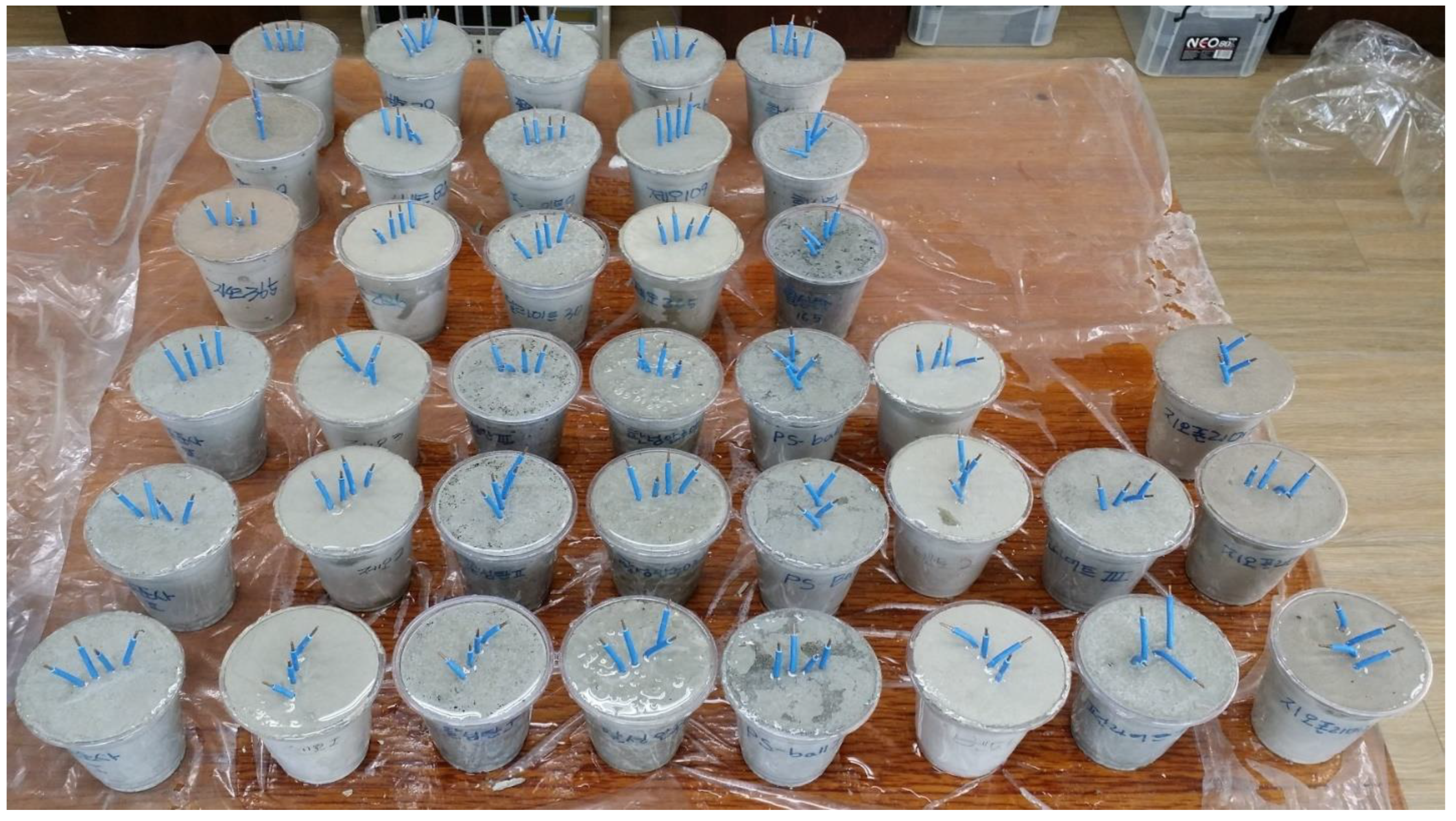
2.1.2. Specimen Preparation

Figure 1 shows the prepared specimens. Specimens were cup-shaped with a top diameter of 15 cm and a height of 20 cm. Ordinary Portland cement and standard sand were selected while adding various admixtures, i.e., activated carbon, bentonite, zeolite, and geopolymer, and chemical agents, i.e., sodium hydroxide, calcium hydroxide, lithium hydroxide, and sodium chloride. The four-probe system suggested by Wenner was designed to measure resistivity [31]; four probes were evenly spaced 1 cm apart.
The mix design is given in Table 1. The primary mixing ratio of cement and sand by weight for general mortar was 1:2, and we reduced the amount of sand while increasing the amount of admixture for the conductive mortar. The admixture ratio is defined as the volume of admixture divided by the volume of admixture and sand. Different admixture ratios of 100%, 50%, 30%, and 10% were selected while the amount of cement was fixed. The amount of water was determined by conducting a flow test and depended on the characteristics of the admixture.
The weight of chemical agents was set to be 1% of the weight of the cement, and the weight of the chemical agents was not included in the mix design. The flow test also determined the amounts of water for the cases with chemical agents, but the amounts were the same as those without chemical agents.

2.2. Results and Discussions

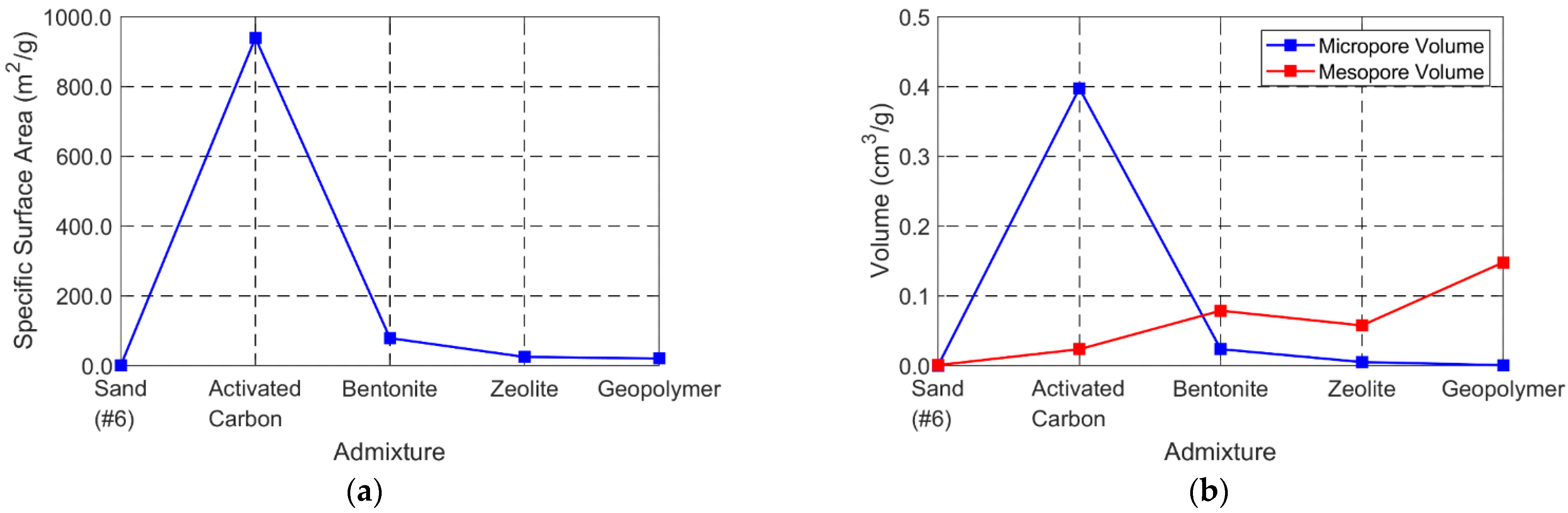
2.2.1. Pore Characteristics

Before measuring the resistivity of the prepared specimens, pore characteristics were analyzed. The specific surface areas, pore volumes, and average pore sizes were measured by adsorbing N2 and measuring its amount (i.e., Brunauer–Emmett–Teller (BET) method). In other words, N2 was adsorbed to four admixtures (i.e., activated carbon, bentonite, zeolite, and geopolymer) and sand, and the above properties were evaluated. The Surface Area and Porosity System (TriStar II 3020, Micromeritics, Norcross, GA, USA) was used for this test. N2 adsorption and desorption isotherms of admixtures were obtained at −195.8 °C, and overnight degassing was conducted at 105 °C. We obtained 99 points to determine the adsorption and desorption isotherms.
Table 2 and Figure 2 provide the measured specific surface areas, pore volumes, and average pore sizes of the four admixtures and sand. In general, it is true that the larger the specific surface area and pore volume, the greater the capacity to store water. The specific surface area of activated carbon is the highest among the five materials, and the four selected admixtures have a higher specific surface area than sand. The pore volume can be used to determine the conductivity of the pores. When the size (diameter) of pores is less than 2 nm, they are classified as micropores; when it is in the range of 2–50 nm, it is classified as mesopores; when it is more than 50 nm, it is traditionally classified as macropores in the field of chemistry according to the International Union of Pure and Applied Chemistry (IUPAC, Zürich, Switzerland). Typically, the mesopore acts as a channel through which moisture can be smoothly supplied into the material, and the micropore adsorbs moisture. While mesopores are developed to some degree, materials with a large volume of micropores play a crucial role in reducing resistivity by adsorbing a large amount of moisture in the pore, which is a favorable condition for conductive mortar. The activated carbon has the largest micropore volume; bentonite, zeolite, and geopolymer follow; and sand has the smallest volumes of mesopores and micropores. Since activated carbon has much larger mesopore and micropore volumes and specific surface area than sand, it can be used as a material for providing large conductivity by mixing a small amount of activated carbon [32]. Based on the results, we can tentatively conclude that activated carbon will be the best material as the conductive mortar, and the resistivity measurement supports this tentative conclusion in the next section.

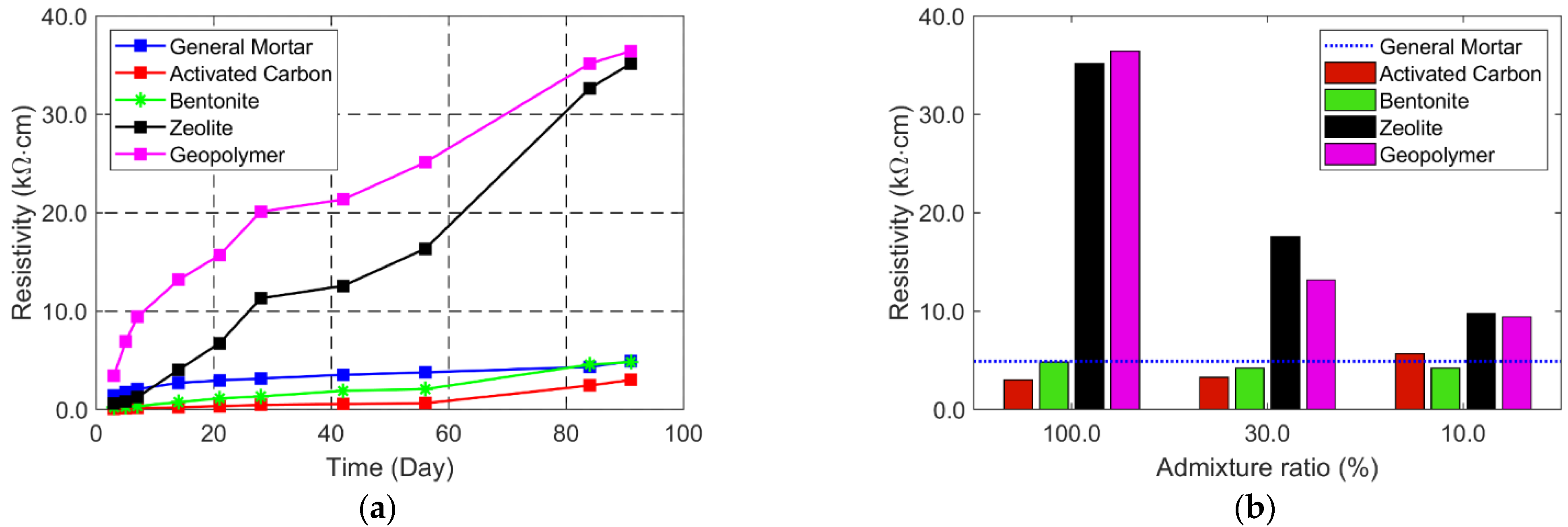
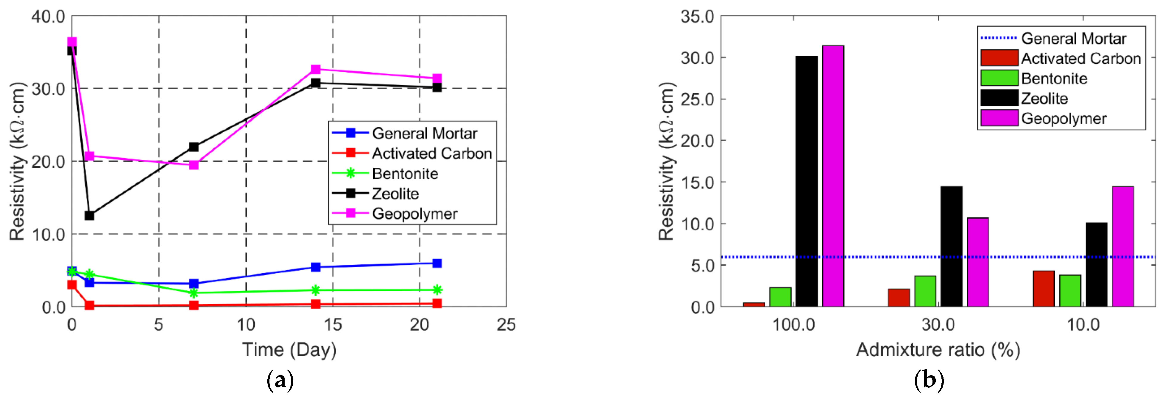
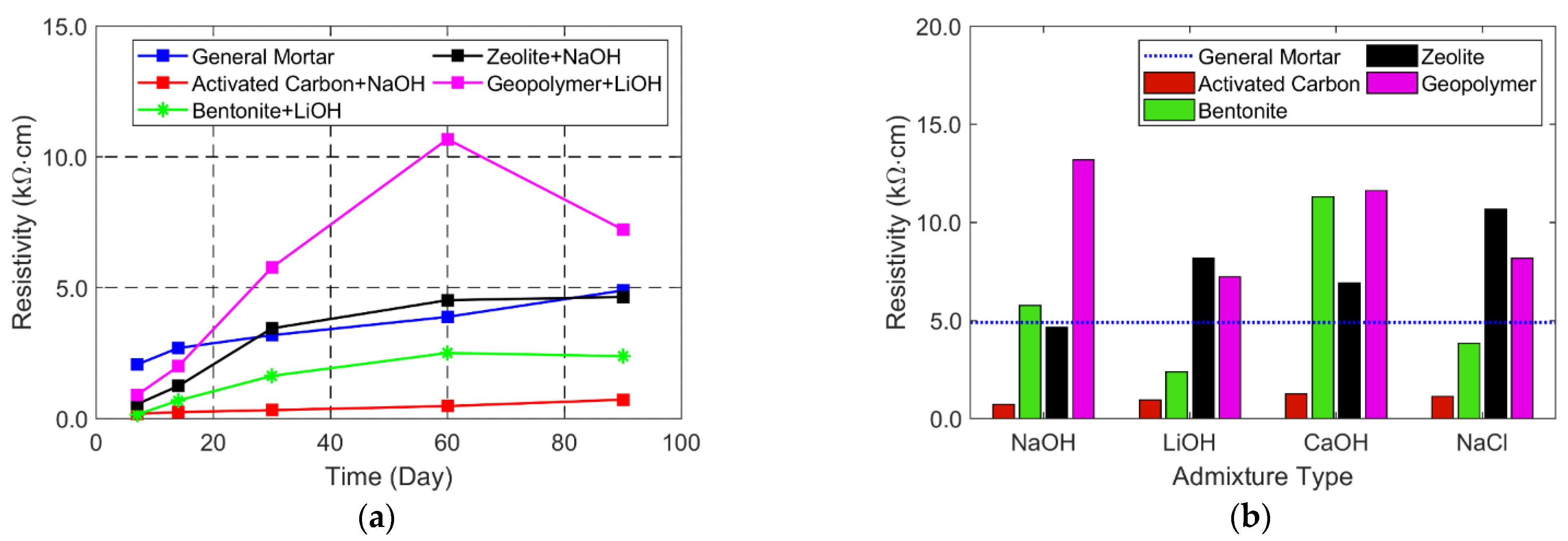
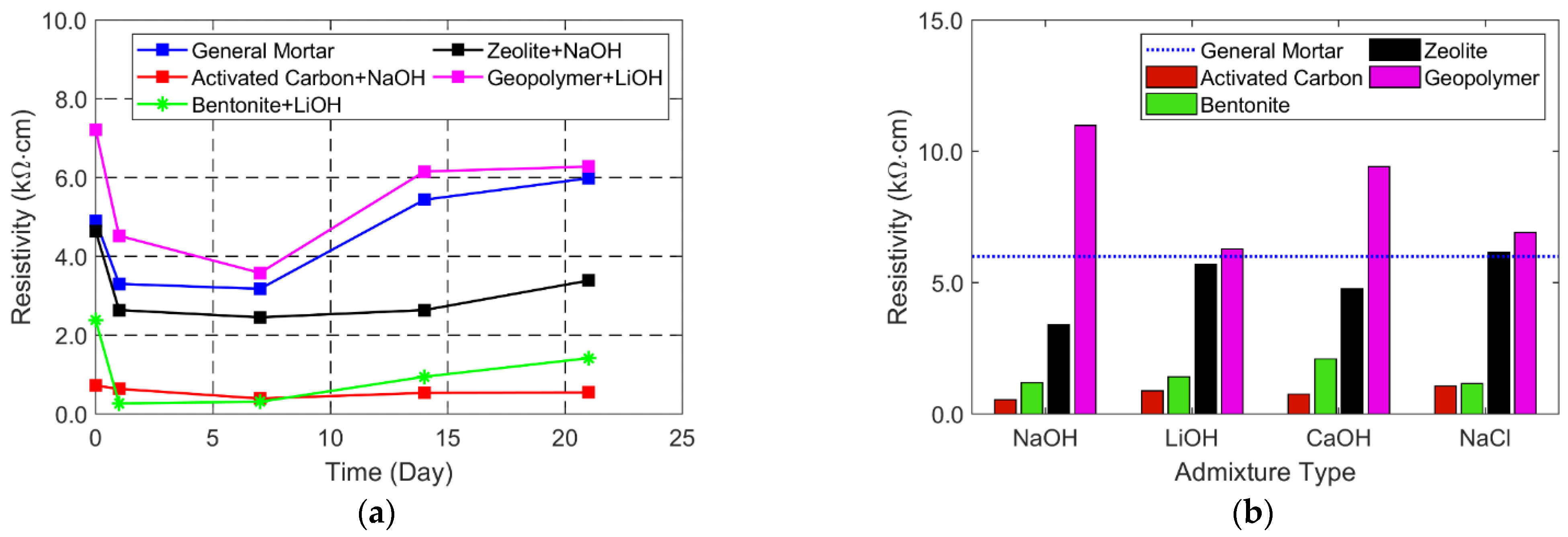
2.2.2. Resistivity Characteristics

The resistivity was measured for 90 days in a dry condition at a lab temperature of 23 °C after the cup-shaped mortar specimens were made. Figure 3a shows the resistivity variations of the general mortar and four proposed conductive mortar specimens with an admixture ratio of 100% for 90 days. Since the moisture content is reduced over time, resistivity tends to increase for all specimens due to reduced moisture content. Zeolite and geopolymer have even higher resistivity than general mortar after 90 days; the higher the admixture ratio, the higher the resistivity for these materials after 90 days, as shown in Figure 3b. As discussed in Section 2.1.1, these materials have higher mesopore and lower micropore volumes than activated carbon and bentonite; moisture can quickly increase or decrease induced by highly developed mesopores. This means that resistivity can promptly increase in dry conditions, as shown in Figure 3. Since SACP requires sufficient and sustainable moisture inside the concrete structures, these materials are not proper candidates.
On the other hand, activated carbon has lower resistivity than general mortar over 90 days, which means that it can maintain the humidity inside the mortar well. Bentonite has a similar resistivity level to general mortar after 90 days. In addition, increasing the amount of these materials helps to decrease resistivity, especially for activated carbon. Thus, these materials can hold moisture inside the mortar for a long time and can be considered conductive materials.
After 90 days, all specimens were immersed in tap water for 24 h. We took out the specimens and measured the resistivity for 21 days to check whether the humidity was well maintained. This test aims to identify whether the proposed conductive mortar can hold humidity for a long time. Figure 4 presents the resistivity change over 21 days. Geopolymer and zeolite quickly reduce resistivity after immersion; they quickly dry out and return to their original dry state in 21 days due to well-developed mesopores. Again, these materials have higher resistivity than general mortar. Considering that sustainable CP is important, quick increase and decrease characteristics are improperly used as the conductive mortar. However, large resistivity reductions are observed for the specimens with bentonite and activated carbon, and these materials have resistivity lower than general mortar. In addition, the resistivity is well maintained over 21 days, which means that the moisture is well maintained inside the mortar. In particular, activated carbon shows excellent performance with low, sustainable resistivity for a long time. In addition, specific surface area, total micropore volume, and average pore size play a role in determining the resistivity, as Table 2 and Figure 2 are compared with Figure 3 and Figure 4; the micropore volume and pore size are key factors in the resistivity while specific surface area is somewhat related.
The same procedures were repeated for the specimens with both admixtures and chemical agents. Various combinations of admixtures and chemical agents were made, and resistivity was measured. As mentioned before, sodium hydroxide (NaOH), calcium hydroxide (CaOH), lithium hydroxide (LiOH), and sodium chloride (NaCl) were selected as chemical agents. Sodium hydroxide, calcium hydroxide, and lithium hydroxide are strong alkali components, and sodium chloride has high electrical conductivity. Specimens with an admixture ratio of 50% were used for this study.
We first measured resistivity for 90 days after specimens were made, as shown in Figure 5. Note that the direct comparison is difficult between the cases with and without chemical agents due to the different admixture ratios. Adding chemical agents change the resistivity significantly. While there are significant resistivity variations within the case with various chemical agents, a proper combination of admixture and chemical agent reduces resistivity. For example, the specimen with Bentonite and LiOH has a resistivity of 2.39 kΩcm, which is even lower than the specimen with bentonite only with an admixture ratio of 100%. In addition, different admixtures have different chemical agents to reduce the resistivity most, but, in some cases, chemical agents contribute to increased resistivity. Among all the combinations, activated carbon with NaOH provides the lowest resistivity, which will be the best solution for the conductive mortar. NaOH is a strong alkali component with high electrical conductivity, and the resistivity is further reduced when activated carbon with a large specific surface area is mixed with NaOH.
Another critical point of our conductive mortar is that our proposed conductive mortar has lower resistivity than the commercially available one. For example, conductive mortar FC200 at Fosroc has a resistivity of 5–10 kΩcm, and the proposed conductive mortar with activated carbon and NaOH has a much lower resistivity of 0.72 kΩcm. Note that a direct comparison between FC200 and the present ones might be difficult since resistivity varies depending on the mixed ratio.
After 90 days, all specimens were immersed for 24 h. Resistivity was then measured for 21 days after samples were taken out. Figure 6 shows resistivity variations during the 21 days after mortar specimens were immersed for 24 h and resistivity of the specimens with different admixtures and chemical agents after 21 days. Again, it was found that the resistivity is lowered with the additional chemical agents. The combination of activated carbon and NaOH is measured with the lowest resistivity, and the most stable results are shown over time. Again, the activated carbon has the largest specific surface area and micropore volume. Thus, when water penetrates the mortar’s surface, resistivity is rapidly lowered and maintained for a long time. In this regard, it was concluded that activated carbon can serve as a conductive mortar to improve the performance of the SACP system.

3. Characteristics of SACP System with Activated-Carbon-Based Conductive Mortar

In Section 2, activated-carbon-based conductive mortar shows not only the highest specific surface area and micropore volume but also the lowest resistivity. Therefore, we further used conductive mortar with activated carbon to check the feasibility of the SACP system with the proposed conductive mortar.

3.1. Experimental Procedure

3.1.1. Mix Design

The mix design is presented in Table 3. Activated carbon was chosen as a conductive material. Different admixture ratios of 0, 5, 10, 15% were selected. An admixture ratio of 0% stands for general mortar. Since the grain size of silica sand No. 6 is similar to activated carbon, the amount of activated carbon increased while decreasing the amount of silica sand No. 6. Furthermore, α-gypsum hemihydrate, expansion agent, lithium, latex resins, silica fume, polycarboxylic acid-based polymer, polyvinyl alcohol (PVA), dispersing agent, and air-entraining agent were mixed as additional admixtures. These materials aim to reduce drying shrinkage, accelerate hardening, and enhance durability, adhesion strength, and strength. In detail, α-gypsum hemihydrate is an expansion agent used to prevent cracks; the expansion agent is a dispersing agent that helps to mix sand, cement, and admixtures; lithium is used to accelerate hardening; latex resin is used to enhance durability and strength; silica fume is used to increase strength; the polycarboxylic acid-based polymer is a high-range water-reducing agent used to enhance the mixing ability; polyvinyl alcohol is used to increase flexural strength and toughness; the dispersing agent is used to prevent separation of materials when pouring; the air-entraining agent is a high-range water-reducing agent used to reduce the amount of water and increase workability. The amount of water was calculated to be 18% of mortar by weight, and the unit quantity was calculated to satisfy workability through a flow test.

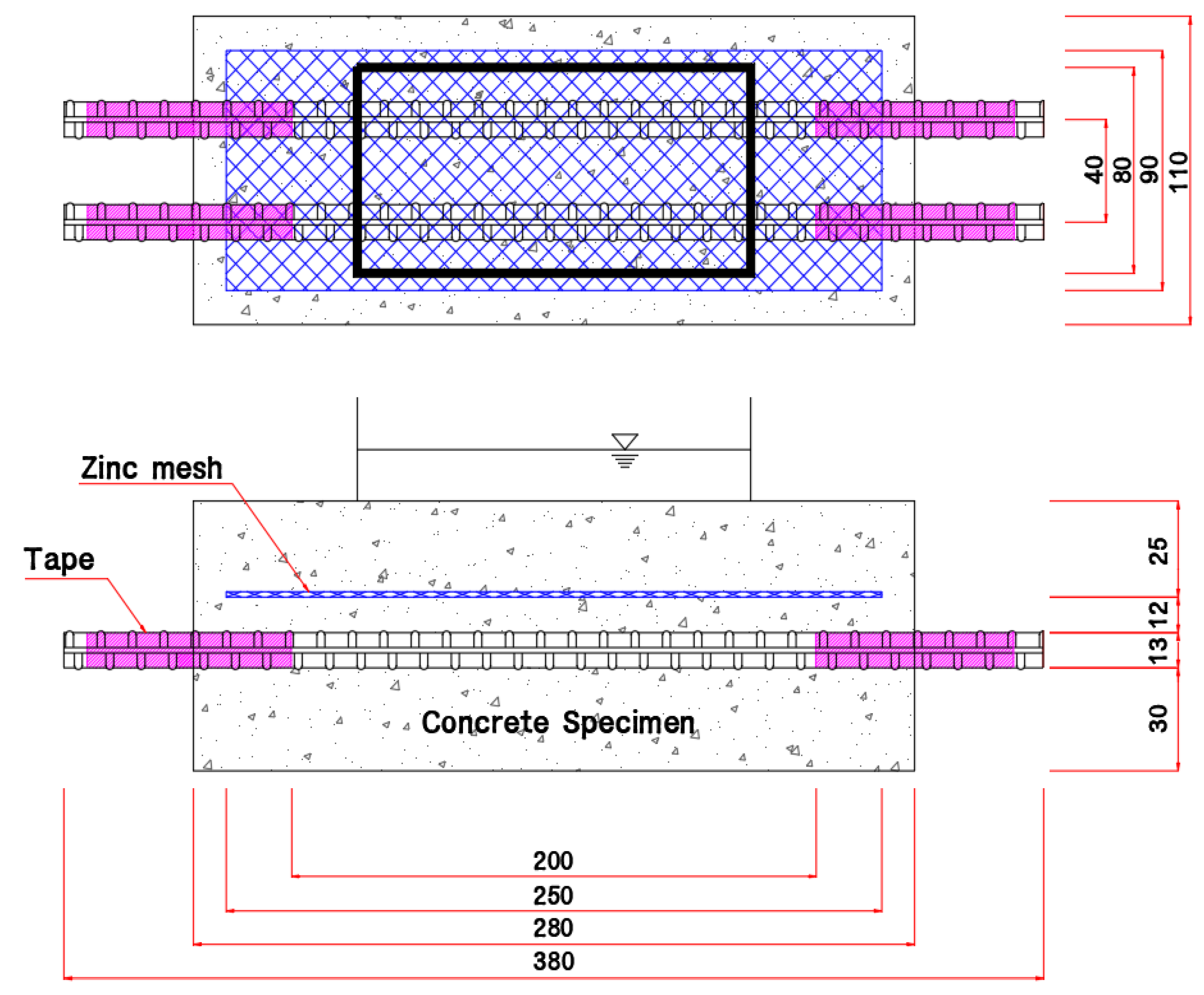
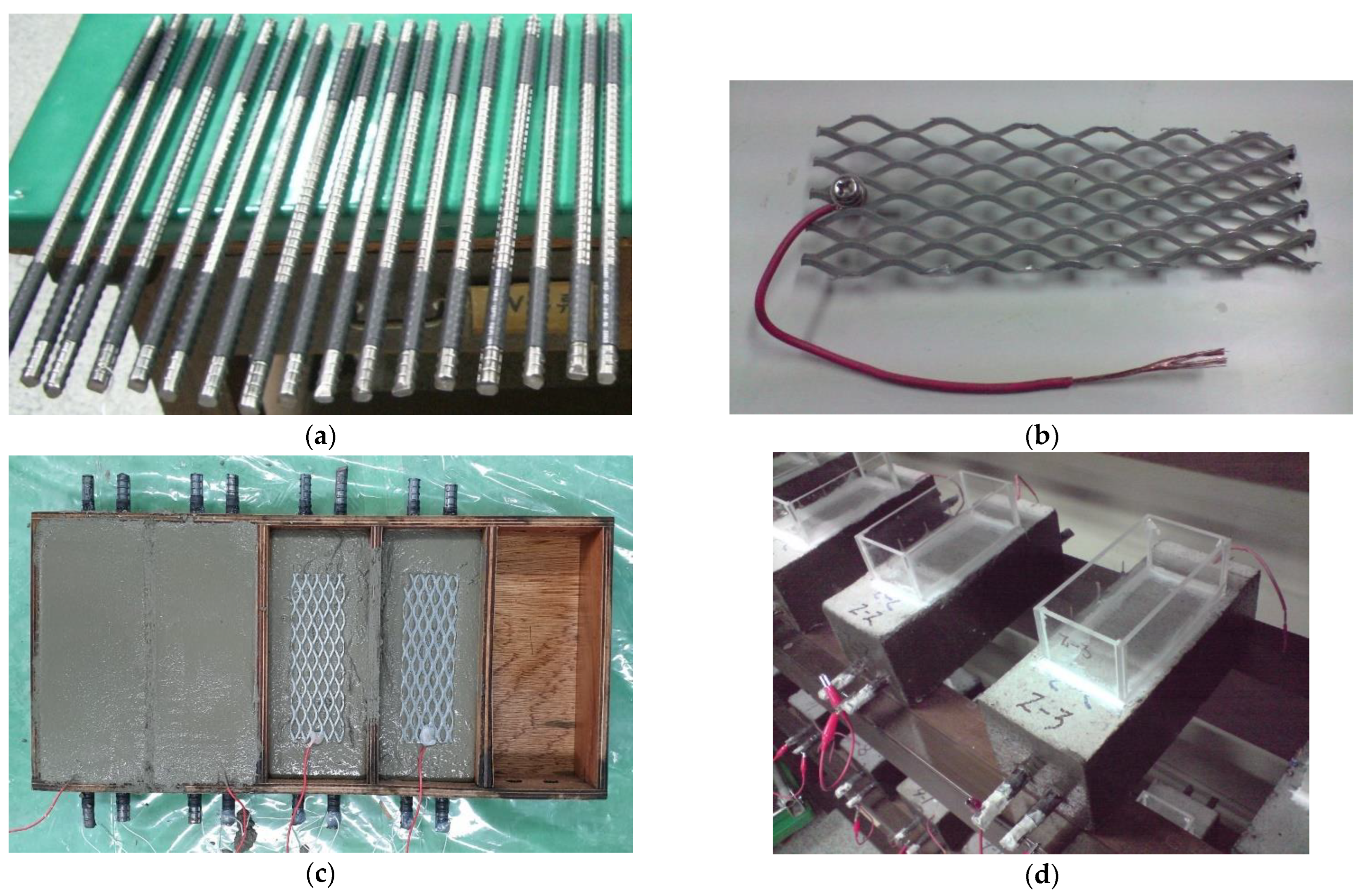
3.1.2. Specimen Preparation

Specimens were manufactured similar to the ASTM G109-92 specimen [29], as shown in Figure 7 and Figure 8. The mortar thickness between the concrete and rebar surfaces was 40 mm. Two parallel rebars were placed at an interval of 40 mm. The SD300 rebar was used with a diameter of 10 mm and a length of 380 mm, as shown in Figure 7. A shrinkage tube (pink area in Figure 7) was used around both ends of the rebar to guarantee the same protection area. A 250 × 90 mm zinc mesh anode was placed between the rebar and concrete surface. The electric wire was connected from the end of the zinc mesh anode to the end of the rebar. The material composition and properties of the zinc mesh anode are presented in Table 4. An acrylic water barrier was installed on the surface to expose the specimens to water.

3.2. Results and Discussions

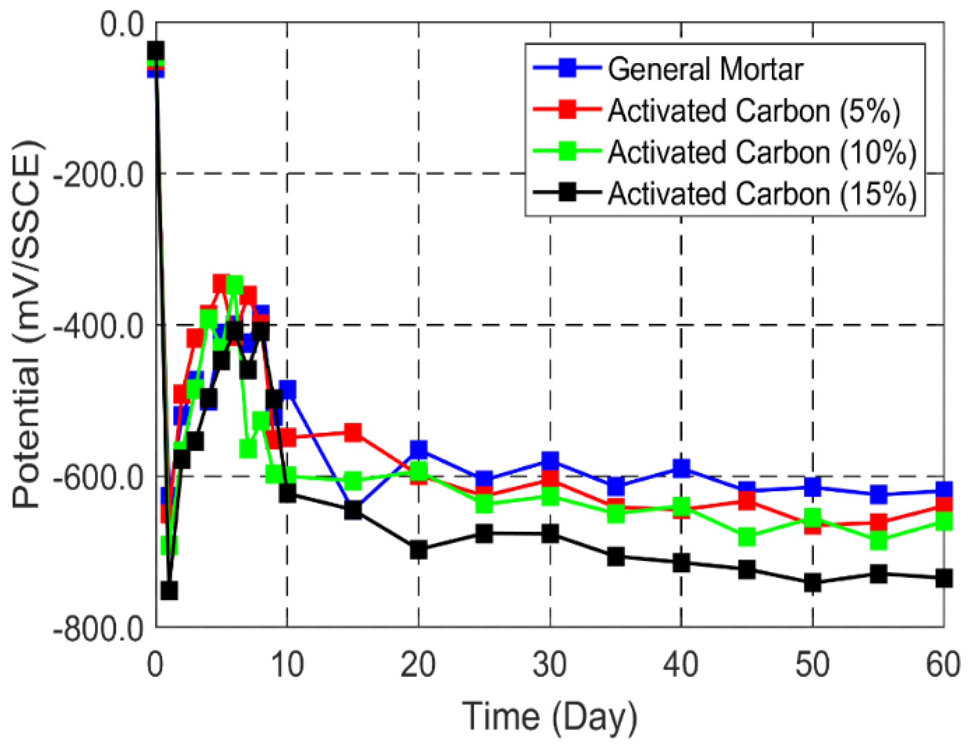
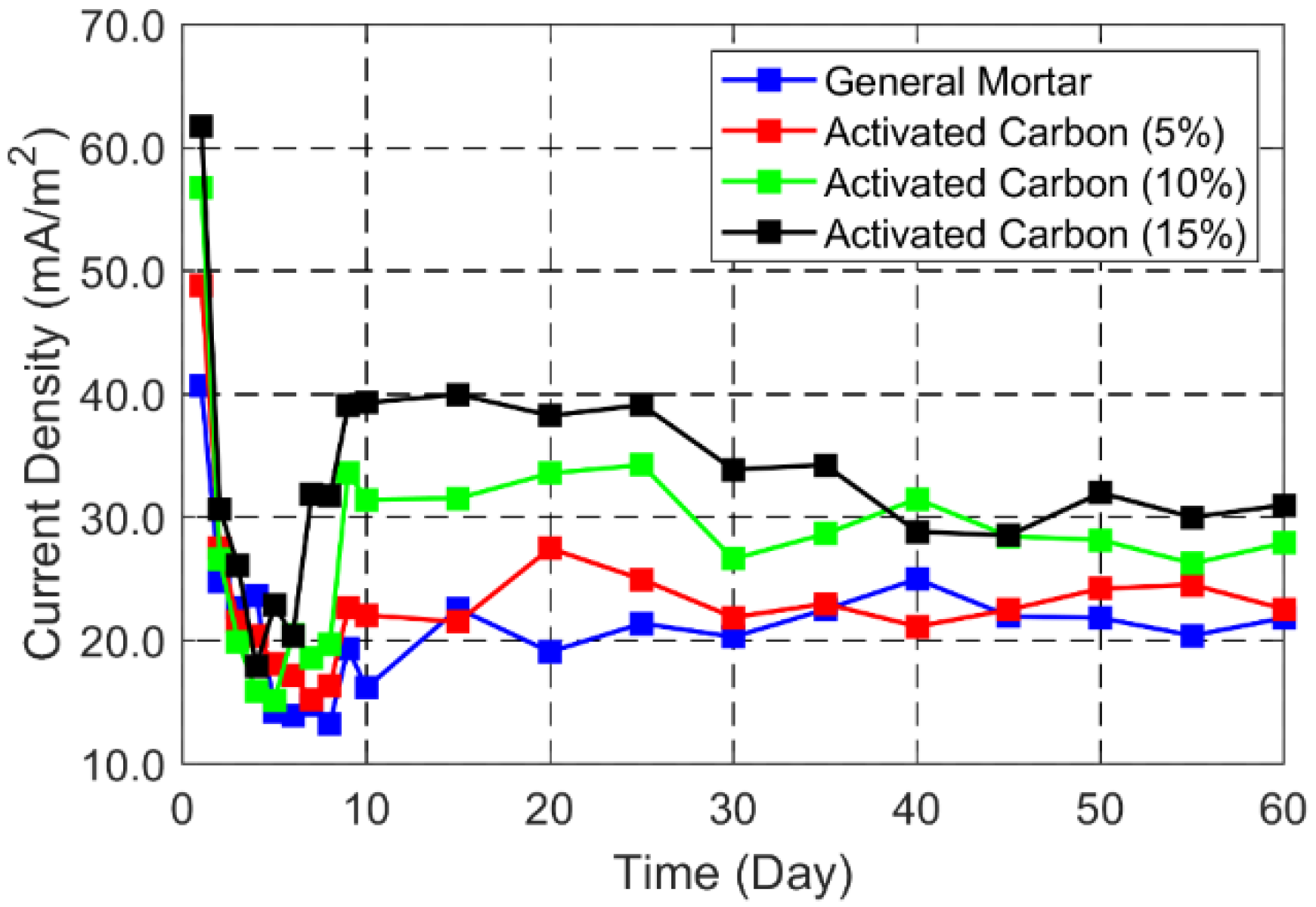
3.2.1. CP Potential and Current Density

After the general mortar and activated-carbon-based conductive mortar (admixture ratios of 5%, 10%, and 15%) specimens were prepared, freshwater was poured into the specimen. After that, potential and current measurements were made for 60 days. Figure 9 shows the CP potential variations. A silver/silver chloride reference electrode (SSCE) was employed for potential measurements. The initial potential before CP application was −61 mV/SSCE for the general mortar specimen and −50, −46, and −37 mV/SSCE for the activated carbon specimen with admixture ratios of 5, 10, and 15%. After applying the CP system, potentials dropped significantly at the initial stage, and fluctuations were observed for six days. The fluctuations in the initial stage were due to the generation of oxide film on the anode. Then, clear indications of a decrease in potential were observed since the oxidation film was well generated. In addition, conductive mortar specimens showed lower potential than the general mortar specimen. The higher the admixture ratio, the lower the potential. Since activated carbon contributes to lower resistivity, a better CP effect can be observed when adding more activated carbon by looking at the potential after 60 days. For example, the specimen with an admixture ratio of 15% can have about 115 mV lower CP potential than the general mortar specimen.
Figure 10 shows the CP current density variations. CP current density was estimated by dividing the measured current by the rebar surface area. A large CP current density was detected during the initial stage. CP current density had large fluctuations during the initial six days and gradually increased for 54 days, which shows the relationship between CP potential and current density. After 60 days, the results showed that the higher the admixture ratio, the higher the CP current destiny. Current density is closely related to the concrete resistivity, and this result further supports the low resistivity observed in activated-carbon-based conductive mortar. The higher CP current in conductive mortar specimens demonstrates that they can provide better CP efficiency. For example, the current density measured in the specimen with an admixture ratio of 15% is 1.4 times higher than that in the general mortar specimen.

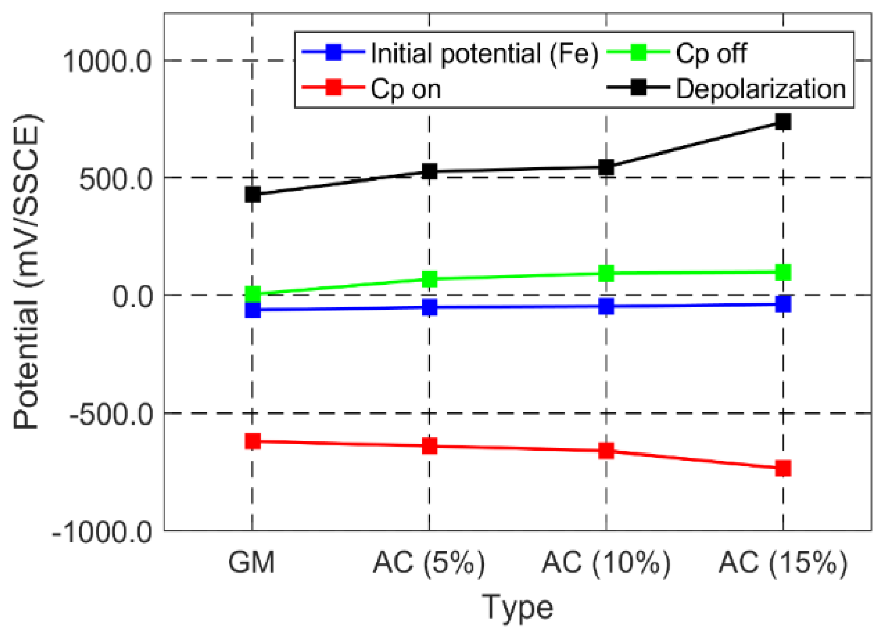
3.2.2. Four-Hour Depolarization Test

Four-hour depolarization tests were carried out after operating the SACP system for 60 days. One of the most widely adopted methods for concrete structures is the 100 mV depolarization criterion in NACE RP0169 [33]. Note that this 100 mV does not include IR drop. Since we poured fresh water on top of the specimen, the IR drop was negligible. Figure 11 shows the 4 h depolarization measurements. The general mortar specimen had a depolarization potential of 430 mV while increased depolarization potentials of 526, 546, and 739 mV were measured for the specimens with admixture ratios of 5, 10, and 15%, respectively. All the specimens had much higher depolarization potentials than the 100 mV criterion since they were exposed to fresh water, and the zinc mesh anode was close to the rebar. However, all conductive mortar specimens had higher depolarization potentials than the general mortar specimens. In addition, the higher the amount of admixture ratio, the higher the depolarization potential (or the higher the CP performance). In places with wet–dry cycles, such as tidal and splash zones, the depolarization potential will be low with the SACP system. A better depolarization potential is essential for these zones, and the proposed conductive mortar specimens can improve the efficiency of the SACP system.

4. Conclusions

This study investigated the possibility of improving cathodic protection (CP) efficiency through the proposed conductive mortar. Laboratory experiments were conducted to first find the best combination of admixture and chemical agent by not only using the Brunauer–Emmett–Teller (BET) method to identify the specific surface areas, pore volumes, and average pore sizes but also the Wenner 4 probe test to measure resistivity. After selecting the best-performed combination with low resistivity and higher specific surface area/micropore volume, the sacrificial anode cathodic protection (SACP) system was tested to check the CP performance. From the laboratory tests, the following key results were obtained:
  • Among admixtures, higher specific surface area and micropore volume result in lower resistivity. A large specific surface area contributes to adsorbing a large amount of moisture, while micropores increase the possibility of maintaining moisture for a long time. Activated carbon has the highest specific surface area and micropore volume; thus, it can hold a large amount of moisture for a long time.
  • Specimens with activated carbon show the lowest resistivity, and adding sodium hydroxide further decreases the resistivity. Sodium hydroxide is a high-alkali component with high electrical conductivity, and the resistivity is further reduced when activated carbon is mixed with sodium hydroxide.
  • Based on CP performance evaluation, lower CP potential and higher CP current density were observed in the proposed activated-carbon-based conductive mortar specimen compared to the general mortar specimen. The higher the admixture ratio, the higher the CP performance, proving that the CP performance can be improved by adding the proposed admixture.
  • The four-hour depolarization measurement showed that all specimens, including the general mortar, have more than 100 mV depolarization since the samples were exposed to freshwater and the rebar was close to the zinc mesh anode; however, the conductive mortar shows higher depolarization potential than the general mortar.
Based on the measurements of resistivity, pore characteristics, CP potential, CP current density, and 4 h depolarization potential, the activated-carbon-based conductive mortar shows excellent performance in the laboratory environment. The proposed conductive mortar with the SACP system was applied to an actual bridge structure in South Korea, and in situ measurement results will be presented to demonstrate its feasibility in Part 2.

Author Contributions

Conceptualization, J.-M.H., C.J. and J.-A.J.; methodology, J.-M.H., C.J. and J.-A.J.; investigation, J.-M.H., C.J. and J.-A.J.; writing—original draft preparation, J.-M.H.; writing—review and editing, C.J. and J.-A.J.; visualization, J.-M.H. and C.J. All authors have read and agreed to the published version of the manuscript.

Funding

This research received no external funding.

Institutional Review Board Statement

Not Applicable.

Informed Consent Statement

Not Applicable.

Data Availability Statement

Not Applicable.

Conflicts of Interest

The authors declare no conflict of interest.

References

  1. Byrne, A.; Holmes, N.; Norton, B. State-of-the-art review of cathodic protection for reinforced concrete structures. Mag. Concr. Res. 2016, 68, 664–677. [Google Scholar] [CrossRef] [Green Version]
  2. Zhou, Y.; Gencturk, B.; Willam, K.; Attar, A. Carbonation-induced and chloride-induced corrosion in reinforced concrete structures. J. Mater. Civ. Eng. 2015, 27, 04014245. [Google Scholar] [CrossRef]
  3. Page, C. Mechanism of corrosion protection in reinforced concrete marine structures. Nature 1975, 258, 514–515. [Google Scholar] [CrossRef]
  4. Jeong, J.-A.; Jin, C.-K.; Kim, Y.-H.; Chung, W.-S. Electrochemical performance evaluation of corrosion monitoring sensor for reinforced concrete structures. J. Adv. Concr. Technol. 2013, 11, 1–6. [Google Scholar] [CrossRef] [Green Version]
  5. Zhou, H.; Xu, Y.; Peng, Y.; Liang, X.; Li, D.; Xing, F. Partially corroded reinforced concrete piers under axial compression and cyclic loading: An experimental study. Eng. Struct. 2020, 203, 109880. [Google Scholar] [CrossRef]
  6. Guo, A.; Li, H.; Ba, X.; Guan, X.; Li, H. Experimental investigation on the cyclic performance of reinforced concrete piers with chloride-induced corrosion in marine environment. Eng. Struct. 2015, 105, 1–11. [Google Scholar] [CrossRef]
  7. Yuan, W.; Guo, A.; Li, H. Experimental investigation on the cyclic behaviors of corroded coastal bridge piers with transfer of plastic hinge due to non-uniform corrosion. Soil Dyn. Earthq. Eng. 2017, 102, 112–123. [Google Scholar] [CrossRef]
  8. Schmitt, G. Global needs for knowledge dissemination, research, and development in materials deterioration and corrosion control. World Corros. Organ. 2009, 38, 14. [Google Scholar]
  9. Koch, G. Cost of corrosion. Trends Oil Gas Corros. Res. Technol. 2017, 3–30. [Google Scholar] [CrossRef]
  10. Pedeferri, P. Cathodic protection and cathodic prevention. Constr. Build. Mater. 1996, 10, 391–402. [Google Scholar] [CrossRef]
  11. de Rincon, O.T.; Hernández-López, Y.; de Valle-Moreno, A.; Torres-Acosta, A.A.; Barrios, F.; Montero, P.; Oidor-Salinas, P.; Montero, J.R. Environmental influence on point anodes performance in reinforced concrete. Constr. Build. Mater. 2008, 22, 494–503. [Google Scholar] [CrossRef]
  12. Christodoulou, C.; Glass, G.; Webb, J.; Austin, S.; Goodier, C. Assessing the long term benefits of Impressed Current Cathodic Protection. Corros. Sci. 2010, 52, 2671–2679. [Google Scholar] [CrossRef] [Green Version]
  13. Cheng, X.; Xia, J.; Wu, R.-j.; Jin, W.-l.; Pan, C.-g. Optimisation of sacrificial anode cathodic protection system in chloride-contaminated reinforced concrete structure. J. Build. Eng. 2022, 45, 103515. [Google Scholar] [CrossRef]
  14. Bertolini, L.; Bolzoni, F.; Pedeferri, P.; Lazzari, L.; Pastore, T. Cathodic protection and cathodic preventionin concrete: Principles and applications. J. Appl. Electrochem. 1998, 28, 1321–1331. [Google Scholar] [CrossRef]
  15. Bertolini, L.; Redaelli, E. Throwing power of cathodic prevention applied by means of sacrificial anodes to partially submerged marine reinforced concrete piles: Results of numerical simulations. Corros. Sci. 2009, 51, 2218–2230. [Google Scholar] [CrossRef]
  16. Van Belleghem, B.; Maes, M.; Soetens, T. Throwing power and service life of galvanic cathodic protection with embedded discrete anodes for steel reinforcement in chloride contaminated concrete. Constr. Build. Mater. 2021, 310, 125187. [Google Scholar] [CrossRef]
  17. Bertolini, L.; Gastaldi, M.; Pedeferri, M.; Redaelli, E. Prevention of steel corrosion in concrete exposed to seawater with submerged sacrificial anodes. Corros. Sci. 2002, 44, 1497–1513. [Google Scholar] [CrossRef]
  18. Kranc, S.; Sagues, A.A.; Presuel-Moreno, F.J. Computational and experimental investigation of cathodic protection distribution in reinforced concrete marine piling. In Proceedings of the Corrosion 97, New Orleans, LA, USA, 9–14 March 1997. [Google Scholar]
  19. Presuel-Moreno, F.; Kranc, S.; Sagues, A. Cathodic prevention distribution in partially submerged reinforced concrete. Corrosion 2005, 61, 548–558. [Google Scholar] [CrossRef]
  20. Jeong, J.-A.; Jin, C.-K.; Chung, W.-S. Tidal water effect on the hybrid cathodic protection systems for marine concrete structures. J. Adv. Concr. Technol. 2012, 10, 389–394. [Google Scholar] [CrossRef] [Green Version]
  21. Jeong, J.; Jin, C. Experimental studies of effectiveness of hybrid cathodic protection system on the steel in concrete. Sci. Adv. Mater. 2014, 6, 2165–2170. [Google Scholar] [CrossRef]
  22. García, Á.; Schlangen, E.; van de Ven, M.; Liu, Q. Electrical conductivity of asphalt mortar containing conductive fibers and fillers. Constr. Build. Mater. 2009, 23, 3175–3181. [Google Scholar] [CrossRef]
  23. Fu, X.; Chung, D. Carbon fiber reinforced mortar as an electrical contact material for cathodic protection. Cem. Concr. Res. 1995, 25, 689–694. [Google Scholar] [CrossRef]
  24. Hou, J.; Chung, D. Cathodic protection of steel reinforced concrete facilitated by using carbon fiber reinforced mortar or concrete. Cem. Concr. Res. 1997, 27, 649–656. [Google Scholar] [CrossRef]
  25. Bertolini, L.; Bolzoni, F.; Pastore, T.; Pedeferri, P. Effectiveness of a conductive cementitious mortar anode for cathodic protection of steel in concrete. Cem. Concr. Res. 2004, 34, 681–694. [Google Scholar] [CrossRef]
  26. Xu, J.; Yao, W. Current distribution in reinforced concrete cathodic protection system with conductive mortar overlay anode. Constr. Build. Mater. 2009, 23, 2220–2226. [Google Scholar] [CrossRef]
  27. Xu, J.; Yao, W. Electrochemical studies on the performance of conductive overlay material in cathodic protection of reinforced concrete. Constr. Build. Mater. 2011, 25, 2655–2662. [Google Scholar]
  28. Carmona, J.; Garcés, P.; Climent, M. Efficiency of a conductive cement-based anodic system for the application of cathodic protection, cathodic prevention and electrochemical chloride extraction to control corrosion in reinforced concrete structures. Corros. Sci. 2015, 96, 102–111. [Google Scholar] [CrossRef] [Green Version]
  29. ASTM G109-99a; Standard Test Method for Determining the Effects of Chemical Admixtures on the Corrosion of Embedded Steel Reinforcement in Concrete Exposed to Chloride Environments. ASTM: West Conshohocken, PA, USA, 1999.
  30. Shobeiri, V.; Bennett, B.; Xie, T.; Visintin, P. A comprehensive assessment of the global warming potential of geopolymer concrete. J. Clean. Prod. 2021, 297, 126669. [Google Scholar] [CrossRef]
  31. Wenner, F. A Method of Measuring Earth Resistivity; US Government Printing Office: Washington, DC, USA, 1916. [Google Scholar]
  32. Yang, R.T. Adsorbents: Fundamentals and Applications; John Wiley & Sons: Hoboken, NJ, USA, 2003. [Google Scholar]
  33. NACE Standard RP0169; Control of External Corrosion on Underground or Submerged Metallic Piping Systems. NACE: Houston, TX, USA, 2002.
Figure 1. Prepared cup-shaped mortar specimens for resistivity measurement.
Applsci 12 12056 g001
Figure 2. Specific surface area (a) and micropore and mesopore volumes (b) of admixtures and sand.
Applsci 12 12056 g002
Figure 3. Resistivity variations during the 90 days after mortar specimens were made (an admixture ratio of 100% for conductive mortars) (a) and resistivity after 90 days at different admixture ratios (b).
Applsci 12 12056 g003
Figure 4. Resistivity variation during the 21 days after mortar specimens were immersed for 24 h (an admixture ratio of 100% for conductive mortars) (a) and resistivity after 21 days at different admixture ratios (b).
Applsci 12 12056 g004
Figure 5. Resistivity variation during the 90 days after mortar specimens were made (a) and resistivity after 90 days (b) at different admixtures and chemical agents.
Applsci 12 12056 g005
Figure 6. Resistivity variation during the 21 days after mortar specimens were immersed for 24 h (a) and resistivity after 21 days (b) at different admixtures and chemical agents.
Applsci 12 12056 g006
Figure 7. Drawing of conductive mortar specimen (units in mm).
Applsci 12 12056 g007
Figure 8. Specimen production with rebar and Zn mesh anode for CP performance evaluation. (a) Rebar; (b) Zn mesh anode; (c) Specimen preparation; (d) Manufactured specimen.
Applsci 12 12056 g008
Figure 9. CP potential variations for 60 days.
Applsci 12 12056 g009
Figure 10. Current density variations for 60 days.
Applsci 12 12056 g010
Figure 11. Depolarization potential measurement.
Applsci 12 12056 g011
Table 1. Mix design.
AdmixtureMixing Ratio (g)Unit Content of
Water in Concrete
(Flow Test Result)
Admixture Ratio (%)
CementSandAdmixtureTotal
Weight
Ratio
(%)
Water (g)
General mortar2505000750181350
Activated carbon250016541544181100
250250825822514550
250350496492013130
250450167161711910
Bentonite250028653656300100
2502501436433119950
250350856852416330
250450287281813010
Zeolite250036561533200100
2502501826822215050
2503501097091813030
250450367361612010
Geopolymer250036561533200100
2502501826822114350
2503501097091812530
250450367361510710
Table 2. Specific surface area, total pore volume, and average pore size of admixtures and sand.
ItemSpecific
Surface Area
(m2/g)
Pore VolumePore
Size
(nm)
Micropore Volume
(cm3/g)
Mesopore Volume
(cm3/g)
Total Pore Volume
(cm3/g)
Sand (#6)0.2390.0000340.0007590.00113.249
Activated
carbon
939.2700.3973240.0234910.4201.792
Bentonite78.5480.0235380.0784830.1025.195
Zeolite24.6950.0050150.0576840.06210.155
Geopolymer20.3370.0005710.1475790.14829.138
Table 3. Mix design.
Activated Carbon Mix Design (OPC:S = 1.45)
Admixture Ratio:
0%
Admixture Ratio:
5%
Admixture Ratio:
10%
Admixture Ratio:
15%
MaterialWeight
(g)
Percentage
(%)
Weight
(g)
Percentage
(%)
Weight
(g)
Percentage
(%)
Weight
(g)
Percentage
(%)
Cement348.4685.28348.4685.28348.4685.28348.4685.28
α-gypsum hemihydrate4.731.164.731.164.731.164.731.16
Expansion agent15.763.8615.763.8615.763.8615.763.86
LI-T2.240.552.240.552.240.552.240.55
Latex resin6.311.546.311.546.311.546.311.54
Silica fume28.576.9928.576.9928.576.9928.576.99
Polycarboxylic acid-based polymer1.130.281.130.281.130.281.130.28
PVA1.220.31.220.31.220.31.220.3
Dispersing agent0.160.040.160.040.160.040.160.04
Air-entraining agent0.030.010.030.010.030.010.030.01
Total powder408.61100408.61100408.61100408.61100
Sand #511619.5911619.5911619.5911619.59
Sand #647680.41446.475.41416.870.41387.265.41
Activated carbon 0029.65.0059.210.0088.815.00
Total sand592100592100592100592100
W/M18018180181801818018
Table 4. Composition and mechanical properties of Zn mesh anode.
Composition % by Weight
Lead0.005 max
Iron0.010 max
Cadmium0.005 max
Copper0.7 to 0.9
Zinc Remaining
Mechanical Properties
Ultimate tensile strength 152–200 MPa
Hardness (Rockwell 15T)59–69
Minimum ductility7.1 mm
Publisher’s Note: MDPI stays neutral with regard to jurisdictional claims in published maps and institutional affiliations.

