

A Theoretical Method for Removal of Gravity-Induced Effects in Silicon Wafer Geometry Measurements

Wooptix S.L. Avda, Trinidad 61 Planta 7, 38204 La Laguna, Spain
*
Author to whom correspondence should be addressed.
Appl. Sci. 2022, 12(18), 9049; https://doi.org/10.3390/app12189049
Submission received: 1 July 2022
/
Revised: 5 September 2022
/
Accepted: 5 September 2022
/
Published: 8 September 2022
Abstract
:In the current study, an improved method to obtain measurements of geometry of silicon wafers capable of removing the effect induced by gravity and the contact of supports is presented. The classical method only requires two measurements, while the proposed method requires several images. Nevertheless, the classical method relies on the perfect placement and alignment of the wafer over the supports, while the proposed method is strongly immune against misplacing and misaligning the wafer from one measurement to another. The mathematical basis for the new method is presented together with results of a simulation that compares the performance of the classical and the proposed method. It is also shown that, for placement errors as small as 100 nm, the proposed method has better results than the classical method.
1. Introduction
Wafer shape or wafer geometry variations, such as bow and warpage, are important parameters in the integrated circuit (IC) manufacturing process. The shape affects wafer handling and the depth of focus if the wafer shape is not perfectly flattened by chucking inside the lithography tool. To correct for process-induced wafer shape differences, the wafer geometry free of gravity needs to be measured [1].
Removing gravity effects from silicon wafer geometry measurements of a wafer resting horizontally produces results equivalent to those that can be obtained when measuring a free and unclamped wafer. After the correct gravity removal of a horizontally held silicon wafer, the effects that the support pins produce on the wafer are effectively removed. This is required to achieve the maximum yield and to monitor the residual stress caused by thermal and mechanical effects during wafer processing [2].
The three basic strategies for gravity removal are outlined in the SEMI MF1390-0218 standard [3]: the Representative Wafer Inversion Method (RWIM), the Sample Wafer Inversion Method (SWIM), and the Theoretical Modeling Method (TMM) [4]. In RWIM, a specially selected wafer is measured, and this measurement is considered the reference gravity effect, which is then removed from every other new measurement. In SWIM, two measurements of each wafer are acquired: the first measurement with the front surface pointing upward and the second one pointing downward. The gravity effect is the mean value of these two measurements [4]. Finally, in TMM, the gravitational effect is derived from a theoretical model. This model is only available for an infinitely small center pin chuck, and the Stoney equation is used for silicon wafers [2]. However, due to the large variations in the specifications of silicon wafers, for example, in thickness and wafer diameter, wafer deflection can range up to 20 µm, making this method useless for current and next-generation IC technology nodes [5].
The work presented in this paper is focused on the SWIM method, where there is neither information about the wafer nor gravity-induced deformations. The reference SWIM method, as published in [6], relies on the perfectly even symmetry of the gravity-induced effect, with any deviation from that making the method inaccurate. In this work, a new method that works even with severe deviations from even symmetry is proposed.
2. Classical Method
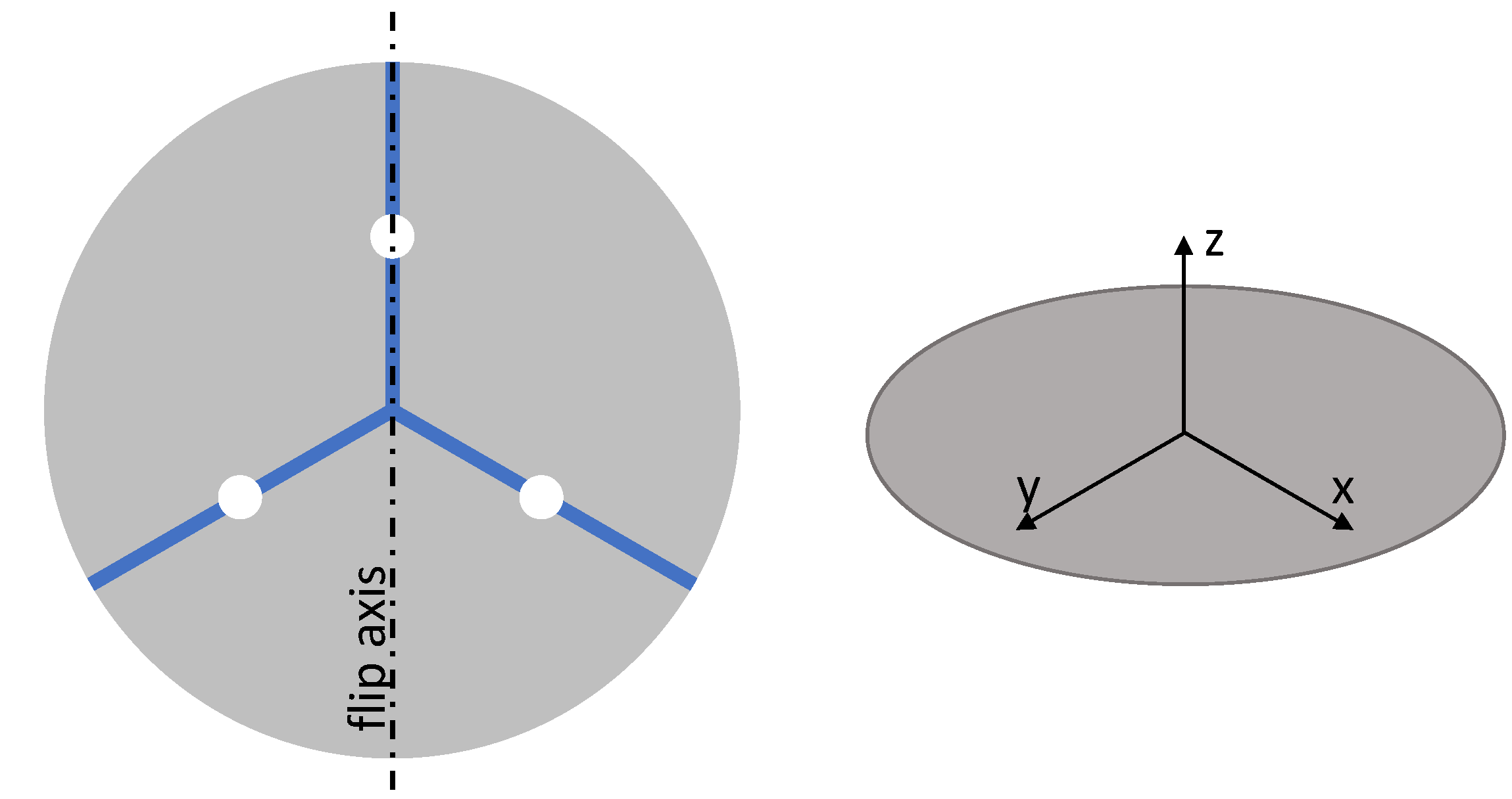
The reference method, as proposed in the SEMI standards [3,7], is usually applied to a one-point or a three-point support setup. When the wafer’s front surface points upward, it is denoted normal orientation, and when the front face points downward, it is denoted inverse orientation. When the wafer is flipped to change from normal to inverse orientation, the flip axis must be chosen carefully so that the relative position of the supports and the wafer remains unchanged (Figure 1). This is achieved by selecting the axis so that the flip operation maintains even symmetry. In a centered one-point support, any axis can maintain even symmetry. However, in a regular three-point support setup, only the axes passing through the center and any of the contact points maintain even symmetry.
The first step of the reference method is to obtain the normal orientation measurement , where and are the wafer plane coordinates. It is assumed that this measurement is the sum of the actual front surface shape of the wafer and the gravity effect [7].
It is also assumed that the gravity effect is identical regardless of whether the wafer is in normal or inverse orientation; the inverse orientation measurement is denoted . It must be noted that, to measure the wafer in its inverse orientation, it must be flipped around an axis. Here, it is assumed that the flipping is carried out around the y-axis, giving formally [7]
The operation of flipping the wafer around an arbitrary axis at degrees with respect to the x axis is defined as . Therefore, the flipping with respect to the y-axis as is referred to as
Considering all these assumptions, the actual wafer shape and the gravity effect can be derived as follows:
The previous pair of equations are strictly true only when the gravity effect is the same in both directions. From a pure mathematical point of view, it must have even symmetry around the flip axis: . Considering only the effect of the wafer supports, either a centered one-point support or a three-point support setup, enables the wafer to be flipped while maintaining even symmetry.
In a real implementation, there are many sources of error that break the needed even-symmetry requirement: the placement error of the supports, the flip axis angle error, the deviation of the wafer perimeter from a perfect circle, thickness variations or mechanical stress resulting from wafer processing, and anisotropy related to the lattice structure of the silicon substrate to list some, even if the silicon wafer is within specifications [5].
In this work, only two symmetry requirements are considered: the placement error of the supports and the flip axis angle error.
3. Proposed Method
In this work, a new method is proposed based on acquiring more than two measurements of the same wafer in order to accurately produce a gravity-removed measurement with greater immunity to misplacement and/or misalignment.
In the proposed method, named Modal Gravity Removal (MGR), one measurement in normal orientation must be acquired as described in Equation (1). The main benefit of this method is its immunity against the lack of even symmetry of the gravity effect, which appears due to the misalignment or misplacement of the wafer over the support pins [5].
After acquiring the measurement in normal orientation, a set of measurements must also be acquired in inverse orientation, whereas the number of measurements N is a variable. In every measurement, the wafer in inverse orientation is rotated at an angle with respect to the z-axis. This set of measurements is finally averaged:
where takes the equally distributed angles in the whole circumference; .
Then, the first estimation of the actual shape of the wafer can be derived using the following assumption: the gravity induced deformation is independent of the rotation of the wafer:
Then, the estimated shape can be composed by subtracting the front and back measurements:
The shape can be split into two components: the non-rotational symmetric (NR) component and the rotational symmetric (RS) component. The NR component moves toward zero when rotated and averaged over an infinite number of angles, while the RS component remains unchanged.
Taking all the above into consideration, the first estimation of the shape can be written as follows:
Then, the estimation of the shape can be calculated as a subtraction of the front and back measurements, and then it can be split into its NR and RS components. The actual shape can then be rewritten as follows:
To split any 2D function into its NR and RS components, the Zernike polynomials are chosen as a base. Zernike polynomials are defined by two indexes, namely, and , which are nonnegative integers; the polynomials are defined only when (Figure 2). Any Zernike polynomial with an even value of and with shows rotational symmetry [8]. Finally, any shape can be rewritten as the sum of Zernike polynomials:
where represents real-valued coefficients; represents integer values larger than 0; and and are the even and odd positive integers, respectively. To limit the processing burden of the method, in this work, the value of is limited to 10. To find the best coefficients , any minimization or least squares method can be applied to solve it.
In Figure 3, the MGR method is summarized in a flowchart. Normal and inverse orientation measurements are two independent processes that can be carried out in any order.
4. Simulation
To evaluate the proposed method in comparison with the reference method, both are simulated; real data cannot be used since there is no way to obtain the geometry of a silicon wafer without any effect induced by gravity. To simulate under realistic measurement conditions, two sources of inaccuracies in the measurement setup are added: the placement error of the supports and the angle of the flip axis.
As previously observed, each measurement, either in the normal or inverse orientations, is composed of the gravity and shape of the wafer.
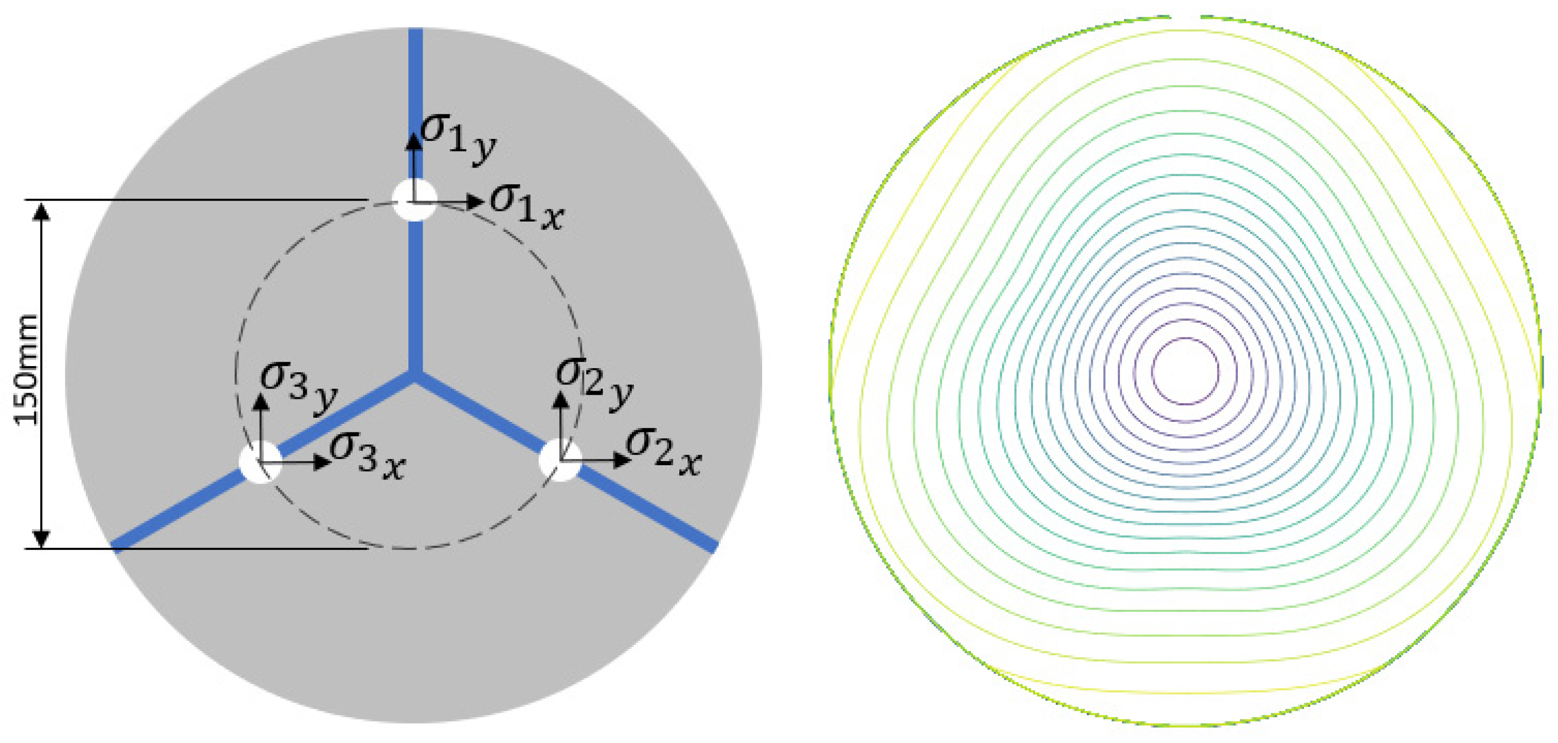
First, the gravity effect is simulated. For this purpose, a set of three spatial positions is defined. This set of positions creates an equilateral triangle with a distance in respect to the center of 75 mm; these points are given a value of 1 on the z-axis. The fourth point is the center of the mass of these three points and is given a value of 0. These four scattered points act as control points, and, finally, they are interpolated to a regular grid of a given sampling interval in order to create a dense grid with the same extension as the wafer (300 mm × 300 mm) (Figure 4). Many methods can be used for this purpose, but thin-plate spline interpolation [9] is used in this work; the mathematical model of this interpolation method is an analogy to sheet metal deformed under stress.
To simulate the placement error of the three-point support, a Gaussian distribution with zero mean and a variable standard deviation is added to the three first control points. The placement error is added in two ways: an independent error for each support and an equal error for every support . The flip angle error is also modeled using Gaussian distribution with zero mean and a variable deviation .
For the reference method, the normal direction measurement is obtained as in Equation (1). The inverse direction measurement is calculated with a certain error in the flipping axis:
Finally, the shape is obtained by applying Equation (4).
In the proposed method, the normal orientation measurement is calculated in the same way as in the reference method. The inverse orientation measurement is obtained by applying Equation (17):
Finally, the symmetric and non-symmetric components are calculated as in Equation (14), and operating with these components using this equation leads to obtaining the final value of .
5. Results
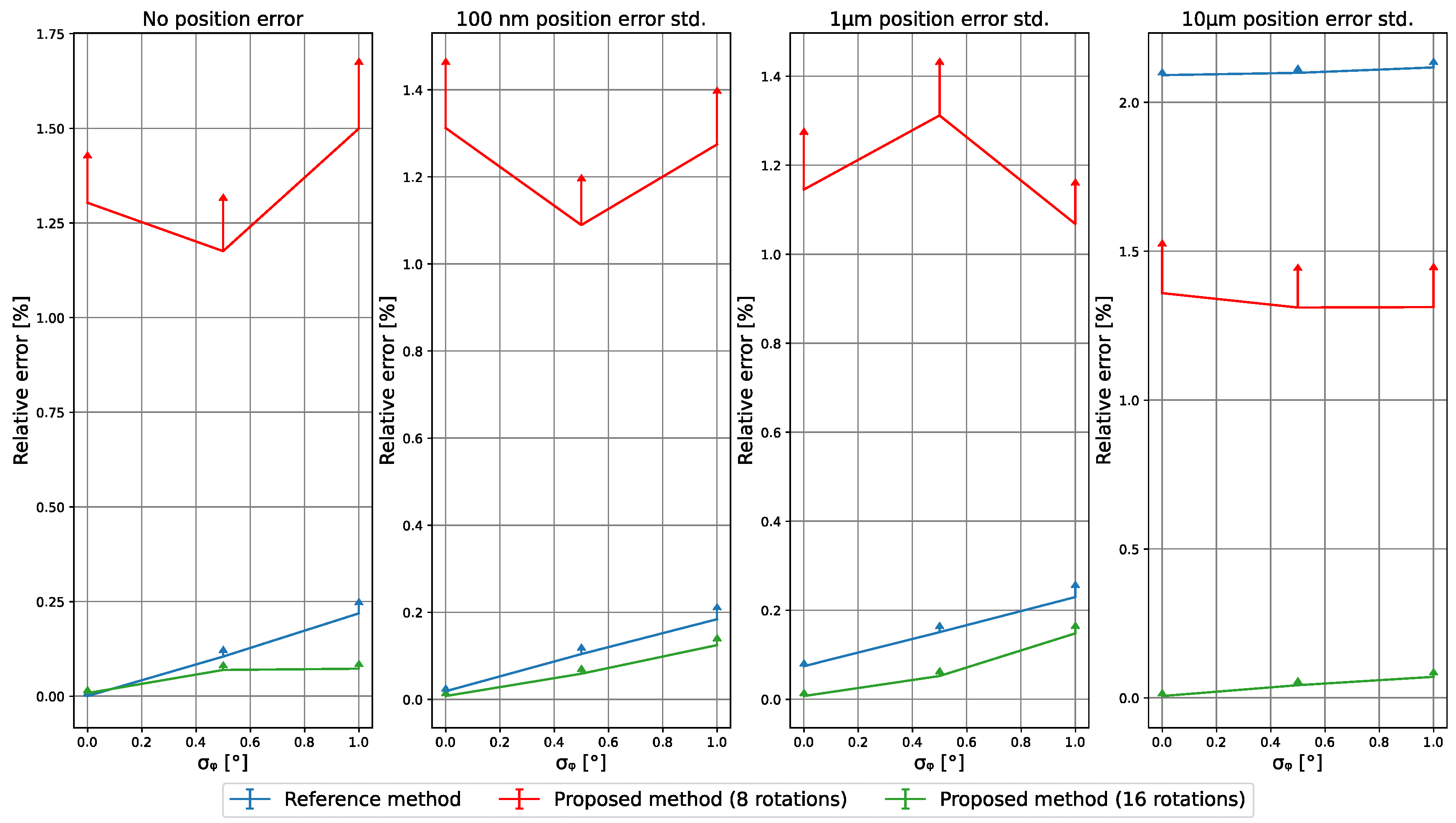
The results summarized in Figure 5 are obtained after averaging 100 measurements for each condition of misalignment angle standard deviation and support position error . In this first set of measurements, the position error is set to be independent for each support . The sampling interval is set to 0.1 mm. Three methods are compared in regard to their ability to remove gravity-induced effects: the reference method [6], the proposed method with 8 rotations (N = 8), and the proposed method with N = 16.
It can be seen that using the proposed method with N = 16 outperforms the reference method, except for in the ideal case of neither error nor misalignment.
In Figure 6, the same simulation is carried out again, but this time, the placement error of the support pins is equal for the three of them , so it creates the same effect of a perfectly machined three-point support; however, the placement of the wafer is not performed perfectly. In this scenario, the proposed method produces similar results to those of the prior case; however, the refence method produces larger errors.
6. Conclusions
It was shown that the reference method for the removal of gravity-induced effects in bow and warp measurements of silicon wafers produces inaccurate results when the placement of the wafer on top of the support pins is not accurate enough. For accuracies of 100 nm or worse, the proposed method is always better than the reference method.
The added cost of the proposed method results from the need to acquire several measurements in the inverse orientation while changing the rotation angle of the wafer. This method should always be used when the tolerance of the support pins cannot be guaranteed or when wafer-placing accuracy is poor, i.e., in hand-operated applications and in general when an accurate measurement free of gravity-induced deformation is the ultimate objective and when the acquisition time can be compromised.
Author Contributions
Conceptualization, J.G. and J.M.T.-S.; Methodology, J.M.T.-S.; Software, J.M.T.-S.; Validation, J.M.T.-S. and J.G.; Formal Analysis, J.M.T.-S.; Investigation, J.M.T.-S.; Resources, J.G.; Data Curation, J.M.T.-S.; Writing—Original Draft Preparation, J.M.T.-S.; Writing—Review and Editing, J.M.T.-S. and J.G.; Visualization, J.M.T.-S.; Supervision, J.M.R.-R.; Project Administration, J.M.R.-R.; Funding Acquisition, J.M.R.-R. All authors have read and agreed to the published version of the manuscript.
Funding
This research received no funding.
Institutional Review Board Statement
Not applicable.
Informed Consent Statement
Not applicable.
Data Availability Statement
The data presented in this study are available on request from the corresponding author. The data are not publicly available due to the theoretical nature of this study.
Conflicts of Interest
The authors declare that there is no conflict of interest.
References
- Freischlad, K.; Tang, S.; Grenfell, J. Interferometry for wafer dimensional metrology. In Proceedings of the Advanced Characterization Techniques for Optics, Semiconductors, and Nanotechnologies III, San Diego, CA, USA, 28–29 August 2007; Volume 6672, p. 667202. [Google Scholar] [CrossRef]
- D’Elia, C.R.; Hill, M.R.; Stender, M.E.; Marchi, C.W.S. Residual Stress, Thermomechanics & Infrared Imaging and Inverse Problems, Volume 6. 2020. Available online: http://link.springer.com/10.1007/978-3-030-30098-2 (accessed on 30 June 2022).
- Materials, S.; Control, P. Semi MF1390-0218 Test Method for Measuring Bow and Warp on Silicon Wafers by Automated Noncontact Scanning. 2003. Available online: ww.semi.org (accessed on 30 June 2022).
- Liu, H.J.; Kang, R.K.; Gao, S.; Zhou, P.; Tong, Y.; Guo, D.M. Development of a measuring equipment for silicon wafer warp. Adv. Mater. Res. 2013, 797, 561–565. [Google Scholar] [CrossRef]
- Categories, S.W. Semi M1-0918 Specification for Polished Single Crystal Silicon; Semi Global: Milpitas, CA, USA, 2018; pp. 1–69. [Google Scholar]
- Natsu, W.; Ito, Y.; Kunieda, M.; Naoi, K.; Iguchi, N. Effects of support method and mechanical property of 300 mm silicon wafer on sori measurement. Precis. Eng. 2005, 29, 19–26. [Google Scholar] [CrossRef]
- Tree, S.D. Semi MF1390-0707 Test Method for Measuring Warp on Silicon Wafers by Automated Non-Contact Scanning; Test, No. Reapproved 0319; Semi Global: Milpitas, CA, USA, 2007; Volume 0707, pp. 1–11. [Google Scholar]
- Noll, R.J. Zernike polynomials and atmospheric turbulence. J. Opt. Soc. Am. 1976, 66, 207–211. [Google Scholar] [CrossRef]
- Keller, W.; Borkowski, A. Thin plate spline interpolation. J. Geod. 2019, 93, 1251–1269. [Google Scholar] [CrossRef]
Figure 1.
Left: layout of a regular three-point support. Right: system of coordinates.

Figure 2.
Zernike modes from to . The rotational symmetry is only shown in modes where n is even, and m is 0.
Figure 2.
Zernike modes from to . The rotational symmetry is only shown in modes where n is even, and m is 0.

Figure 3.
MGR method flowchart.

Figure 4.
Left, three-point support layout. Right, contour map of a dense gravity effect.

Figure 5.
Relative RMS error of the reference and the proposed methods for independent error case. The vertical axis shows the relative error between each result and the ground truth. The horizontal axis shows the misalignment error. The vertical arrows show the standard deviation of the measurement.

Figure 6.
Relative RMS error of the reference and the proposed methods for equal error case. The vertical axis shows the relative error between each result and the ground truth. The horizontal axis shows the misalignment error. The vertical arrows show the standard deviation of the measurement.
Figure 6.
Relative RMS error of the reference and the proposed methods for equal error case. The vertical axis shows the relative error between each result and the ground truth. The horizontal axis shows the misalignment error. The vertical arrows show the standard deviation of the measurement.

Publisher’s Note: MDPI stays neutral with regard to jurisdictional claims in published maps and institutional affiliations. |
© 2022 by the authors. Licensee MDPI, Basel, Switzerland. This article is an open access article distributed under the terms and conditions of the Creative Commons Attribution (CC BY) license (https://creativecommons.org/licenses/by/4.0/).
Share and Cite
MDPI and ACS Style
Trujillo-Sevilla, J.M.; Gaudestad, J.; Rodríguez-Ramos, J.M. A Theoretical Method for Removal of Gravity-Induced Effects in Silicon Wafer Geometry Measurements. Appl. Sci. 2022, 12, 9049. https://doi.org/10.3390/app12189049
AMA Style
Trujillo-Sevilla JM, Gaudestad J, Rodríguez-Ramos JM. A Theoretical Method for Removal of Gravity-Induced Effects in Silicon Wafer Geometry Measurements. Applied Sciences. 2022; 12(18):9049. https://doi.org/10.3390/app12189049
Chicago/Turabian StyleTrujillo-Sevilla, Juan M., Jan Gaudestad, and José M. Rodríguez-Ramos. 2022. "A Theoretical Method for Removal of Gravity-Induced Effects in Silicon Wafer Geometry Measurements" Applied Sciences 12, no. 18: 9049. https://doi.org/10.3390/app12189049
Note that from the first issue of 2016, this journal uses article numbers instead of page numbers. See further details here.