
Performance and Measurement Devices for Membrane Buildings in Civil Engineering: A Review
by
 ,
,
Haonan Huang
1,*,
Xiongyan Li
2,
Suduo Xue
2,
Yaozhi Luo
1,
Da Shi
1,
Xianghua Hou
3,
Yiwei Liu
4 and
Ning Li
5 1
College of Civil Engineering and Architecture, Zhejiang University, Hangzhou 310058, China
2
College of Civil Engineering and Architecture, Beijing University of Technology, Beijing 100124, China
3
Institute of New Functional Materials, Guangxi Institute of Industrial Technology, Nanning 530001, China
4
College of Civil Engineering, Hunan University, Changsha 410082, China
5
School of Engineering, University of Glasgow, Glasgow G12 8LT, UK
*
Author to whom correspondence should be addressed.
Appl. Sci. 2022, 12(17), 8648; https://doi.org/10.3390/app12178648
Submission received: 22 July 2022
/
Revised: 24 August 2022
/
Accepted: 26 August 2022
/
Published: 29 August 2022
(This article belongs to the Section Civil Engineering)
Abstract
:Lightweight and flexible membranes offer different façades for buildings (suitability, competitive costs, durability, and other benefits) compared to traditional building materials. Increasing attention is being paid to membrane structures in the civil and industrial sectors. Acquiring response data or environmental characteristics directly from a model or building is the most straightforward approach to analyzing the properties of membrane structures, which also contributes to the development of theoretical studies and simulation methods along with the enactment of specifications. This paper provides a comprehensive overview of membrane structure performance, including mechanical, thermal, and energetic aspects, alongside the deployment and deflation of inflatable types. Furthermore, the devices used to monitor the structural response are summarized. The constitution of the structure is the most critical factor affecting its performance. A proper design would offer enhanced mechanical properties and thermal environments with a reduction in energy consumption. Non-contact measurement technology has the advantage of causing no structural disturbance and is low cost, but it lacks practical application in membrane buildings. The achievements and limitations of previous studies are also discussed. Finally, some potential directions for future work are suggested.
1. Introduction
The evolution of membrane structures can be traced back to tents made of bark or animal skins by ancestral people [1]. The idea for modern membrane structures stemmed from William Lanchester’s use of membrane cloth to build a field hospital in 1917, but it was not realized until 1946, when Walter Byrd constructed a hemispherical radome [2]. Membrane structures have gathered an enormous amount of interest in the past decades for their various appearances and short construction cycles as permanent or semi-permanent buildings [3], along with their excellent portability and adaptability in the field of temporary construction [4]. Moreover, the installation of membrane components in existing buildings has proven to be effective and economical in improving the performance of buildings [5,6]. In recent years, cases of applying membrane structures have shown a solid upward trend, benefiting from the development of architectural membrane materials and the improvement of construction technology. In China, the number of new inflatable membrane structures built each year exceeds 100 [7]. In North America, 60% of low-slope buildings use membrane structures as roofing systems [8]. In Germany, the market for membranes in uprated building waterproofing grew 4.5 times from 2012 to 2017 [9].
The significant deformation of the membrane under external loads is a distinctive feature. Consequently, the mechanical performance of the membrane structure has become a major concern. Energy consumption in the building sector accounts for 40% of primary energy consumption [10]. As green concepts prevail today, striking a balance between energy consumption and the internal temperature environment is a widespread theme in membrane building advancement. Furthermore, the deployment efficiency of inflatable membrane structures and their safety during deflation have been analyzed [11,12].
On the other hand, it is hard to determine the architectural performance of membrane structures based on the research findings on traditional structures, as the gap between membrane materials and traditional building materials is pronounced [12]. A lightweight and flexible nature signifies that the structure exhibits intense geometric nonlinearity [13]. Accurate structural analysis is essential for membrane buildings and facilitates the formation of design principles [14]. A material model, such as a mesostructure or continuum model, is generally established for accurate theoretical or simulation research analysis. Mathematical models [15], fabric lattice models [16], spatial truss models [17], and finite element cell models [18] are common forms of mesostructural models based on the structure and deformation mechanisms of coated fabrics. Continuum models assume that the coated fabrics are homogeneous, anisotropic, and continuous, for which they directly adapt to the analysis of the structure. Although theoretical studies and numerical simulations reveal the structural properties of membrane structures to some extent, the reliability of the results would probably be affected by the simplification of structural aspects or the adoption of the models mentioned above, which are often applied in the analysis process [19]. Analyzing data obtained from models or buildings permits a more accurate determination of the structural performance of membrane structures. Meanwhile, the theoretical equations are verified, and the finite element model can be modified.
This paper provides a systematic review of the performance of membrane structures based on experimental or measured data from five perspectives: mechanics, thermotics, energy, deployment, and deflation. The related measurement devices are enumerated and compared. At the end of the paper, the achievements and shortcomings of the existing research are summarized, and potential future research directions are indicated. A general overview of the above topics is conducive to developing membrane structure specifications and promoting applications in more fields.
2. Membrane Structure
The properties of membrane materials are the most distinct evidence of the uniqueness of membrane structures. The fabrics and composites adopted in membrane buildings are depicted in Figure 1. The most widely adopted membrane materials include polytetrafluoroethylene (PTFE), polyvinylchloride (PVC), polyvinylidene fluoride (PVDF), and ethylene tetrafluoroethylene (ETFE) [1,20]. Different types of membranes are designed by incorporating materials in different ways. However, 90% of the membranes employed in building structures have been categorized into a few limited production methods [21]. As shown in Figure 2, the type of membrane material chosen is governed by the purpose of the building.
In engineering practices, membrane structures are classified as tensioned, skeleton, cable–membranes, or inflatable based on architectural shape and support circumstances [23]. Membrane roofs, membrane ceilings, and hybrid membranes are included in addition to these basic varieties, depending on service requirements [5,24,25,26].
In a tensioned membrane system, steel construction components akin to cables serve as the boundary. To reach the final shape and bear load, the pretension of the membrane is performed by tensioning the boundary or a jacking structure [27]. The main components of the structure are a spatial hyperbolic tensile membrane, supporting mast system, supporting cable, and edge cable. Tensioned membrane structures are generally employed in large public buildings due to their distinctive structural form, which allows for a wide range of design options [28]. The skeleton membrane structure is supported by a spatial grid structure. The membrane, as a subsidiary component in the structure, primarily provides a shielding effect [29]. The prime load-bearing frame of the cable–membrane structure is the space cable system, which differs from the skeleton membrane structure in that the membrane materials are deposited and fastened to the cable system according to functionality [23]. Unlike other types of membrane structures, stable configuration and load-bearing capacity are achieved in inflatable membrane structures by forming pressure differences between the inside and outside of the membrane. It can be divided into four categories according to the different forming methods of the enclosed space: air-supported membrane structure, air-inflated membrane structure, air cushion membrane structure, and airbag membrane structure [7]. These four major membrane structures are shown in sequence in Figure 3.
Membrane roofs offer a competitive alternative to traditional roofing systems due to their durability, low cost, and limited environmental impact. They have been employed extensively in low-slope commercial and industrial structures [33]. Membrane ceilings have gained much interest in recent years due to building energy efficiency standards, making them one of the tactics for achieving low energy consumption because of their ability to expand or retract on demand. The hybrid membrane structure comprises two types of membrane structures or structures combined with other components to meet specific needs. For example, inflatable beams (air beams) have a low bending stiffness and tend to fold or buckle when loaded [34]. The stiffness of a structure is increased by raising the internal pressure. Nonetheless, the safety of the structure is compromised by high internal pressures. The main components of the construction, according to the concept of tensairity, are air beams, struts, and cables [35]. In this system, the compressive loads in the structure are carried by the struts, while the cables bear tensile loads. The purpose of the air beam is to keep the entire structure stable so that just a tiny amount of pressure is required. Gong et al. [26] presented a fairly large movable laboratory. The air-supported membrane structure was the main structure of the laboratory. The air-inflated membrane structure was integrated with an air-supported membrane structure to allow it to be set up with a 22 m wide and 20 m high gate, which allowed the complete structure to retain its shape despite the air-supported membrane structure depleting its load-bearing capacity. Figure 4 depicts the four types of membrane structures addressed in this paragraph.
3. Performance
3.1. Mechanical Performance
3.1.1. Concentrated Load
In the laboratory, it is not practical to apply uniform loads on the exterior surfaces of structures such as inflatable beams and arches due to features of their shape. External loads are typically applied to one or multiple portions of the structure to evaluate its performance. Loading methods include hanging heavy objects and the forced displacement of the experimental setup [35,37].
The most fundamental inflatable membrane structures are inflatable arches and inflatable beams. The deformation of an air beam under external load follows the Timoshenko beam theory rather than the Bernoulli beam theory since the influence of shear stress can hardly be ignored [38,39,40]. As illustrated in Figure 5, the distribution of the load has a notable impact on the degree of deformation and the magnitude of the ultimate bearing capacity, and the internal pressure of the structure determines the time when wrinkles emerge. The bearing capacity of an inflatable arch and beam after wrinkling was strengthened by attaching reinforcing straps outside, according to Brayley et al. [37], and the form of the straps had a considerable impact on the initial stiffness of members. Guo et al. [4] investigated the structural performance of a full-size inflatable arch frame 10.5 m high, 25 m long, and 20 m wide. The spatial action of the structure was demonstrated to play a role in mitigating the deflection of the inflatable arch under load. Under tension, the inflatable arch structure with horizontal coupling beams had a higher lateral stiffness than under compression. Membrane wrinkling had little effect on structural stiffness. The deformation of the structure when the inflatable arch frame was subjected to vertical or horizontal loading is shown in Figure 6.
Tensairity is a type of hybrid structure in which the shape considerably affects its performance. The tensairity of the spindle shape demonstrated better stiffness under any load condition when compared to the standard cylindrical shape [34]. When the internal pressure of an air beam is low, the lateral deformation under vertical load is greater than the vertical deformation, resulting in insufficient tensairity component coupling [41]. Increasing the air pressure permits the components in the structure to be in a superior state of interaction and simultaneously enhances the stiffness of the structure [42]. However, as shown in Figure 7, the increased amplitude decreases gradually, a phenomenon that also exists in inflatable arches and inflatable beams. The load–displacement curve of the first cycle of the structure under cyclic load differs from the curves of the second and third cycles due to the flexible member in the structure, whereas the curves of the two and three cycles remain comparable [43]. As the compression member in the structure, almost all the compressive loads on the structure are borne by struts, with the air beam essentially bearing none of it [42]. Under the action of shear load, the tendency and magnitude of the deformation of the upper compressive members and the lower tensile members of the structure are considerably different [43,44]. As the load increases, the strut shifts from a balanced displacement to a maximum displacement located between the midspan and support, while the maximum displacement of the cable remains in the midspan. The entire strut is M-shaped, with a displacement magnitude more significant than the cable. Tensairity modes are classed as in-phase or out-of-phase depending on their relationship with the internal pressure of the air beam [45].
Wever et al. [46] investigated the reinforcing effect of installing fabric webs in an air beam on the structure. According to the experimental results, the axial stiffness and flexural loads of the structure were heightened by the fabric webs, which were more visible at higher internal pressures. Moreover, Galliot and Luchsinger compared the differences between fabric webs and steel cables for structural reinforcement [35]. When fabric webs and cables were bonded to the air beam, the ultimate load was increased by three and two times under symmetrical loading, respectively, with the weight of the structure increasing by 12 and 29%. Under asymmetric or mid-span concentrated load, the additional fabric webs of the structure performed better. In contrast, the spindle with cables outperformed them under symmetric load, indicating that the shear stiffness played a vital role under asymmetric or mid-span concentrated load, and the influence of tensile stiffness under symmetric load was minimal. Wan et al. [47] explored the application potential of a tensairity dome. Under full-span load, the ultimate load of the tensairity dome was more extensive than a half-span load, demonstrating that such structures are susceptible to asymmetric stress. The buckling of the struts was the failure pattern of this structure under vertical load, making the strengthening of the struts conducive to improving the load-carrying capacity of the structure.
3.1.2. Uniform Load
The membrane surface is uniformly loaded to evaluate the structural performance in most air-cushion membrane structure experiments. Categories of load are classified as internal pressure and external load. Typical loading equipment includes pressure control devices and sandbags.
Since the internal pressure of the air cushion is the primary factor affecting the amplitude of the stress, and internal pressure was dramatically affected by temperature disparity, both parameters require additional consideration in practical applications [48]. The ETFE cushion with a higher arch has minor surface displacement and stress when the same internal pressure is applied [49]. Both the maximum principal strain and maximum principal stress of the membrane occur in the middle of the edge and propagate toward the center of the cushion [50,51,52]. ETFE cushion continuous creep in normal working conditions is directly manifested by the increase in deformation and the decrease in the maximum stress of the structure [53,54]. The weld between ETFE membranes provides local strengthening but has little effect on the stress distribution [55]. In order to make the air cushion equally loaded and the pressure effortlessly adjustable, Zhao et al. [50,56] designed a load simulation chamber (Figure 8) to analyze the mechanical performance of the ETFE cushion. The observations of the experiments revealed that the deformation of the loaded layer of the ETFE cushion was uneven and position-dependent. Under wind pressure and suction, the breakdown modes of the ETFE cushion were radically dissimilar. The cushion was rendered ineffective by edge tearing when subjected to wind pressure, while excessive wind suction ripped holes in the weld.
3.1.3. Wind Load
In practical application, the membrane is generally located on the outer surface of the structure as a sheltering or facade element [57]. The negative pressure of airflow on the membrane is the leading cause of its failure, which means it is difficult to ignore the influence of wind load. Wind tunnel tests and field measurements are direct and efficient methods to acquire the wind load response of membrane buildings. Some studies achieve this purpose through specially designed devices (Figure 9). The advantage of laboratory experiments (such as through wind tunnels) is that conditions can be tailored to fulfill the necessities [24]. However, most wind tunnel experimental models are rigid rather than aeroelastic [36], and the model is simplified after scaling. These two factors make field measurement research unavoidable, even though obtaining a stable reference pressure and determining a time segment to calculate the average wind speed remain difficult [36].
Membrane Roof
The transfer path of wind-induced loads on membrane roofs (i.e., conventional roofing assembly) falls into two categories: structural and pneumatic [8]. A mechanically attached roof system (MARS) is considered to have a structural load path. In this kind of system, the membranes are connected with the components through fasteners in the welding position, making this part most vulnerable to wind suction. It signifies that the welding method has a profound influence. The fastener-centered two-side welding system outperforms the unilateral system in terms of wind uplift rating since one-sided welding is prone to peeling, which should be avoided [60,61]. The membrane-width-to-fastener-row ratio crucially influences the failure load of fasteners and is not affected by the size [33]. A partially attached roof system (PARS), in which the membrane clings to a mechanically attached component, is associated with a pneumatic load path. Different fixing methods for membrane materials do not result in the ballooning deformation of a PARS under wind loads such as in a MARS [8]. Curing time is the crucial parameter to determine PARS resistance to wind uplift. With an increase in curing time, the wind resistance of PARS shows an upward trend and eventually stabilizes [59]. Therefore, protective measures should be taken before reaching complete curing. Chavez et al. [8,24] compared the differences between MARS and PARS through the Natural Hazards Engineering Research Infrastructure (NHERI) Wall of Wind (WOW) Experimental Facility (Figure 10) and in situ experiments. The pressures recorded on PARS were higher than those recorded on MARS but lower than those recorded on plywood roofs, indicating that the deformation of the membrane under load facilitates the relief of external pressures. The extent of reduction is determined by the position of the seam in a MARS [8].
Tensioned Membrane Structure
Wind tunnels are utilized for most experimental programs on tensioned membrane structures. The models are classified as rigid or aeroelastic, depending on the material. Wind pressure is calculated by employing the rigid model, and wind-induced vibration is explored using the aeroelastic model [62]. Since the membrane structure easily deforms under external load, if the shape of the rigid model is an undeformed construction shape, the data obtained deviate from the actual situation. Hincz et al. [30] found that the positive pressure coefficient on the windward side was larger than that on the undeformed side by comparing the surface wind pressure data gathered from two rigid models of undeformed and deformed horn-shaped tension membranes, whereas the negative pressure coefficient on the leeward side was lower, which can be observed in Figure 11.
During wind-induced vibration, the pattern of the surrounding airflow is altered by the membrane, causing the structure to oscillate at a lower frequency than in a vacuum, an effect known as added mass [63,64]. The added mass increases with the increase in wind speed and immensely impacts the displacement of the structure [62]. Daw and Davenport [65] found that the additional mass could be up to 10 times the structural mass. However, contradictory results were reported by Yang et al. [63]. The magnitude of the added mass in dynamic interactions was found to be almost the same as the mass of the structure, with the added mass in static interactions being smaller relative to the dynamics.
Numerous vibration modes are typically excited by the wind, and the amplitude and damping ratio are positively proportional to wind speed [66]. Flutter occurs when the membrane deflects in a divergent direction and takes the shape of standing waves [67]. In addition, only one vibration mode is excited when aeroelastic instability happens in the tension membrane caused by vortex-induced resonance and belongs to periodic destabilization [68].
Sun et al. [69,70] evaluated the wind pressure distribution characteristics of ridge–valley and oval-shaped arch-supported membrane structures. The analysis revealed that the most unfavorable wind direction for an open structure differed from that of an enclosed structure. The surface of the open structure was primarily affected by positive pressure. The rise–span ratio was the parameter that had the most substantial effect on the structure. In the case of oval-shaped arch-supported structures, the influence of parameters on the windward side outweighed the influence on the leeward side. In real-world engineering applications, such as multi-bay horn-shaped membrane structures consisting of various identical unit systems, Nagai et al. [71] discovered that the wind load coefficients of the stand-alone model could practically fulfill the research of open structures. In contrast, enclosed structures need to be examined by adopting the multi-bay model.
Skeleton Membrane Structure
A skeleton membrane structure is commonly utilized as the roof of a massive stadium. Nevertheless, its properties complicate the wind field surrounding it. Through field measurements of the skeleton membrane roof of a stadium, Jiang et al. [58,72] discovered that the correlation of wind pressure between the measuring spots on the leeward side was worse than on the windward side, and there was a substantial time delay. At the edge of the windward side, a negative correlation was observed between the wind pressure on the upper and lower surfaces. Furthermore, the upper surface of the membrane had more potent non-Gaussian characteristics than the rigid construction, which displayed the reverse features, with non-Gaussian behaviors mainly on the leeward side. Kim et al. [31] analyzed measured data from the long-span roof structure of the World Cup Stadium in Jeju-do, Korea, and found that when the vibration amplitude increased by five times, the natural frequency was decreased by 5%, and the damping ratio was increased more than twofold.
Air-Supported Membrane Structure
Each component of the air-supported membrane structure is flexible, resulting in more obvious deformation under wind load. Yin et al. [19] analyzed the wind response data of a pneumatic membrane sports hall. It was discovered that the structural deformation caused by wind load did not substantially impact the internal pressure of the structure. The lateral and vertical deformation of the structure along the airflow direction was more notable than in the longitudinal direction. The deformation of the structure under wind is shown in Figure 12. The influence of wind on the top cable network was the most prominent, as evidenced by the cable strain at the roof ridge being comparatively higher than at the edge. Wood et al. [73] fabricated a hemispherical air-supported inflatable membrane scale model using silicone and experimented with the fluid–structure interaction in a wind tunnel. The wall–normal velocity component and Reynolds stress distribution near the flexible model were significantly attenuated compared to the rigid model. Fluctuations near the turbulent boundary layer had no apparent effect on the structural excitation regardless of the model features.
3.1.4. Impact Load
It is challenging to disregard the impact effects created by external collisions that induce high vibrations in membrane structures. In nature, the impact load on the structure has unknown properties, resulting in stochastic vibration and deformation [74]. Large deformations may reduce the structural pretension, rendering the structure unserviceable afterward when subjected to wind loads below the design value [75]. Similarly, a low tear strength in the membrane leaves the structure susceptible to scratches and punctures by impact objects [76]. Therefore, impact load is an essential factor that has to be considered in the design of membrane structures, but it is not included in the calculation of the load–effect combination in existing design codes and standards of membrane structures [77].
The experiment of the planar membrane with the self-made ballistic launcher or drop-weight machine is the basic approach to studying the influence of impact load on a structure. Guo et al. [78] examined the effect of pretension on vibration induced by impact load. When pretension increased, the amplitude of the vibration frequency increase was nonlinear and showed a downward trend. Moreover, Li et al. [79] found that pretension plays a dominant role in stochastic vibration relative to other parameters. Strong random vibration had pronounced nonlinearity. The probability density function (PDF) results of the dynamic response were close to Rayleigh distribution. Weak random vibration had a tendency to be linear, while the PDF results appeared to follow a Gaussian distribution [79,80]. For the circular tensile membrane, the smaller the radius, the larger the maximum amplitude, velocity, and acceleration and the smaller the natural frequency, reflecting the more significant dynamic response [81]. Xu et al. [82] reported that, in the early stages of the vibration, high-frequency vibrations were induced due to the interaction between the incident waves from the impact and the reflected waves from the side cables, as illustrated by the M-shape in the peak displacement region of the displacement time curve in Figure 13. Furthermore, the maximum incident displacement increased with the increase in pretension.
As an extreme natural phenomenon, hail is a typical impact load on structures. Liu et al. [75,77,83] designed an experimental device to study the effects of hail on saddle-shaped and umbrella-shaped tensile membranes. Silicone balls of different sizes were utilized to mimic hail and randomly impacted the membrane surface through a sieve, as shown in Figure 14. Under normal conditions, hail did not cause structural failure. However, a considerable displacement of the membrane surface was caused by the impact of hail, which might render plastic strain on the membrane and cause a severe decline in structural pretension. For the saddle-shaped tensioned membrane, the loss of pretension was mitigated by the increasing rise–span ratio [75].
Rainfall generally has no noticeable effect on membrane structure, but the dynamic response caused by heavy rainfall has attracted attention in recent years. Artificial rainfall devices are able to successfully simulate rainfall parameters consistent with natural rainfall and successfully regulate parameter variation, which is one of the approaches to examining the impact of heavy rainfall on structures [84]. An artificial rainfall device is shown in Figure 15. Li et al. [85] reported that the diameter of raindrops and their impact loads on a structure followed the Weibull distribution and generalized extreme value distribution, respectively. The displacement response of the structure obeyed non-Gaussian distribution with tail characteristics. Stronger nonlinear vibrations were excited by water accumulation in a horizontal membrane structure according to Zheng et al. [86], whereas the vibrations of an inclined membrane structure were regarded as linear. Liu et al. [84,87] investigated the influence of heavy rainfall on the umbrella-shaped tensile membrane. Heavy rainfall did not immediately cause membrane damage in the trials, but the vibration generated by heavy rainfall caused irreversible deformation in the structure, resulting in a drop-in pretension of more than 8%. The decrease in pretension might lead to a bagging effect of water accumulation on the surface, which then causes structural failure.
3.1.5. Wrinkle
Membranes are prone to wrinkling when subjected to compressive or shear stresses due to their low bending stiffness. The local wrinkling occurs when the maximum compressive or shear stress exceeds the uniform critical value [88]. Wrinkles in membranes are a localized buckling phenomenon that decreases the performance and stability of the structure, so it is an important task to minimize or avoid wrinkles in membrane structures. The complex wrinkling effect plays a significant role in the deformation process, making it difficult to predict the buckling properties of the structure through theoretical methods. Therefore, experiments and numerical simulations are the main approaches to investigating membrane wrinkling, especially for inflatable structures [89].
The local buckling of existing wrinkles, along with changes in local modes, is the causal factor leading to the creation of new wrinkles [90]. The initial imperfections in membrane thickness can significantly affect the distribution of wrinkles, and the shapes of the wrinkles are not unique when the membranes are repeatedly deformed under the same conditions [90,91]. Moreover, the wrinkles’ shapes influence the membrane’s vibration modes, and the stresses in the wave peaks of the wrinkles are larger than those in other parts of the membrane [92]. The critical wrinkle strain of the membrane can be calculated from the out-of-plane displacement and the in-plane stress, where the mean principal stress of the membrane increases as the shear displacement increases [93].
Inflatable beams and arches as load-bearing components gradually decrease in flexural load capacity with the occurrence and propagation of wrinkles [94]. The development of inflatable structural wrinkles with increasing load is shown in Figure 16. The critical wrinkle load is sensitive to the load location, internal pressure, and material properties, where the magnitude of the critical load increases when the load location moves away from the middle of the inflatable beam [89,95,96]. Xue et al. [89] found that the bending wrinkle characteristics of the structure are poorly related to the boundary conditions and the shape of the structure based on the pseudo curved beam (PCB) model. However, Liu et al. [88] reported a contradictory conclusion based on the Fourier model, finding that the boundary conditions strongly influence the wrinkling behavior of the structure.
The minimization or avoidance of wrinkles is a precondition to ensure that the structure maintains its performance given the adverse effects of wrinkles on membrane structures. Wang and Tan [97] installed shape memory alloy (SMA) wires on the stretching side of an inflatable beam corresponding to a wrinkled area, which effectively controlled the number of wrinkles. Similar results were obtained by Tao et al. [98], where structures designed based on the mesh reinforced membrane (MRM) concept restricted the evolution of wrinkles. For tensioned structures, Liu et al. [99] found that wrinkles are effectively reduced by trimming the edges of rectangular membranes into curved lines.
3.2. Thermal Performance
3.2.1. Thermal Environment
Membrane structures, unlike traditional structures, have limited temperature inertia and poorer insulation due to the thickness of the membrane and its high transparency, resulting in a structure whose serviceability is chiefly dependent on temperature influences and typically has poor thermal comfort [100,101,102,103]. Therefore, the thermal environment is essential for evaluating membrane structures [1]. Additionally, the solid space- and time-dependent characteristics of the structural temperature environment make onsite measurements the most appropriate method for acquiring building performance [104].
Depending on the layout of the building, the spatial environments of buildings containing membrane structures are divided into enclosed and non-enclosed. The effect of indoor height on the temperature in enclosed areas is that, at the same horizontal position, height is positively associated with temperature and its variation range, and the peak time of the temperature curve is delayed as height decreases [105,106]. Nevertheless, thermal stratification is limited as the ventilation system operates [101]. He et al. [100,107] delved into the summer temperature environment of a semi-enclosed space beneath a membrane structure. The ground temperature was increased during the daytime due to solar transmission through the membrane, causing a mean radiant temperature (MRT) and thermal comfort index (SET*) of the living space higher by 4 °C and 2–4 °C compared with ambient air temperature on sunny days with low ventilation conditions. At night, the MRT was 2 °C warmer than the air owing to the radiation–cooling–shading effect of the membrane and the thermal-storing effect of the ground. Ambient heat distribution within the structure is shown in Figure 17. Hu et al. [104,105] evaluated the temperature environment of an enclosed large-span membrane stadium. It was found that the temperature differential between the inside and outside of the closed environment was 6.2 °C in summer, which was higher than the semi-closed climate, and it dropped to 3.1 °C in winter. The influence of airflow on temperature distribution was comparatively lower than the effect of solar irradiation since the airflow in the room remained largely static under natural ventilation settings. The predicted mean vote (PMV)–predicted percentage dissatisfied (PPD) method was introduced and used to evaluate the thermal comfort of the gymnasium. It was discovered that the inside environment was unsatisfactory most of the time without external measures. Bai et al. [103] found that periodic outdoor temperature alteration causes more dramatic fluctuations in the temperature field inside the membrane structure, with a delay time of less than one hour between indoor and outdoor air temperatures. Tang et al. [108] reported the effect of double ETFE cushion structures and a ventilation system on the internal temperature field of the National Aquatics Center in China. When solar radiation intensity reached 800 W/m2, the indoor sensible heat load was 238 W/m2, and the dry bulb temperature in the ample space was 3.5 °C lower than the black bulb temperature in the inhabited zone with no shading devices and no ventilation equipment. A drop of 7.3–10.5 °C in the air temperature in the cavity between the cushions inside the roof of the double ETFE cushion structure occurred when the airflow rate of the ventilation system reached 830,000 m3/h. In the industrial sector, membrane structures are often used in warehouses to reduce dust pollution caused by open-air storage. Compared to public buildings, there is less emphasis on the indoor environment of industrial buildings, which makes the indoor temperature environment of such warehouses more susceptible to the external environment. Tian et al. [109,110] explored the relationship between indoor temperature and time within a day in a membrane-structured storage building using field measurements and experiments on a scaled-down model. The findings revealed that solar radiation and outdoor air temperature have a near-instantaneous effect on indoor air temperature. The indoor air temperature varied dramatically throughout the day, between 08:00 and ’20:00, except between 08:00 and ’10:00, when the indoor temperature was lower than that outside, as illustrated in Figure 18.
Attaching components consisting of insulating materials to the membrane structure with the aim of minimizing the temperature effect is an alternative solution. Hu et al. [102] evaluated the effect of membrane structures incorporating or not incorporating aerosol materials into the indoor environment of buildings. The interior comfort level of buildings using aerogel materials was upgraded by one level, while the PPD was reduced by 50%, according to the PMV-PPD method. Another study showed that aerogel–glass wool material could effectively attenuate ambient radiant heat and reduce the impact of sunlight on the room regardless of the angle of incidence [106].
On the other hand, membrane structures are employed in some buildings to improve the indoor temperature environment. Hu et al. [5,111] studied the influence of retractable membrane ceilings on a large-span swimming stadium. Retractable membrane ceilings are an active measure to vary the indoor temperature environment, enhancing indoor airflow when folded and maintaining a stable indoor temperature when unfolded. By considering different combinations of parameters, the average temperature differences between the lower and upper parts of the ceiling when unfolding and folding the membrane ceiling were 0.91 °C and 0.065 °C (membrane ceiling), 0.91 °C and −1.17 °C (membrane ceiling and air conditioning), and 1.02 °C and −1.24 °C (membrane ceiling, air conditioning, and solar radiation), respectively, as with the average temperature differences between the indoor floor and outdoor: 6.58 °C and 2.93 °C (membrane ceiling), 10.7 °C and −1.31 °C (membrane ceiling and air conditioning), and 9.65 °C and 0.12 °C (membrane ceiling, air conditioning, and solar radiation). Moreover, a similar experiment was carried out in a residential building [6]. Analogous results were reported for the average temperature discrepancy of 3.7 °C and 0.9 °C between the first and second floors when the membrane roof is unfolded and folded. The presence of the membrane ceiling allowed for a smoother temperature variation on the first floor. The relationship between temperature variation over time is shown in Figure 19.
3.2.2. Thermal Characteristics of the Structure
The temperature has a considerable effect on the performance of the membrane structure itself. For multilayer membrane structures, the temperature variation in the membrane material on the side directly exposed to hot and cold air is drastic. However, the temperature difference on the other side is not comparatively pronounced due to the low thermal conductivity of both the material and the air between the membranes [11,112]. The degree of deformation in a structure under external load decreases as the temperature drops, but the load-carrying capacity does not substantially improve [11]. Furthermore, the natural frequency of the structure and the internal force of the cable are both decreased as the temperature drops [31,113].
3.3. Energy Consumption
Statistics show that the building sector accounts for about 30% of overall energy requirements [114]. In contexts where the concept of energy-saving is receiving increasing attention, it is a trend to improve the energy performance of buildings.
The design of buildings plays a major role in energy efficiency. Suo et al. [101] assessed the energy consumption disparities between three membrane structure designs: single-layer, double-layer of cushions, and double-layer with a continuous air gap. The energy savings of the second and third designs were found to be 11% and 18%, respectively, compared to the single-layer design. However, the single-layer structure might accomplish the same result by adding a low-emissivity coating or lowering infiltration losses. Furthermore, utilizing natural light through the light transmission of membrane material helps lower the energy necessary for artificial lighting [115].
Incorporating photovoltaic (PV) panels into the membrane structure converts solar energy into electrical energy to provide the membrane with the ability to maintain itself and reduce the need for additional energy. The conversion efficiency of photovoltaic panels is approximately 5–19% [116,117]. Hu et al. [118,119] found that the average power consumption to output ratio of ETFE cushion-integrated PV panels was greater in sunny weather than in sunny-to-cloudy weather. It was confirmed that the cushion could operate appropriately without an external power source. The relationship between energy usage and output is depicted in Figure 20.
3.4. Deployment and Deflation
3.4.1. Deployment
Inflatable arches, inflatable tubes, and other similar structures are capable of rapidly achieving their design shape and have a certain load-bearing capacity, enabling them to be utilized in emergency construction (military tents, makeshift hospitals) [37]. Both the dynamic deployment characteristics of such buildings and the feasibility of self-erection are directly related to the time required for on-site construction.
For the inflatable arch, the geometric configuration and the way it is placed on the ground before inflation are the key factors affecting its deployment. Easier dynamic deployment of the structure and lower peak pressures during inflation are made possible by larger arch diameters and lower heights. The arches are more challenging to deploy in-plane before inflation than out-of-plane and may lead to difficulties in self-erection without external support [11]. There is no fixed location where wrinkles appear in the structure during the inflation process, as the location may vary between the previous and subsequent inflation under the same conditions [112]. Li et al. [11] conducted an inflation test on a large inflatable arch frame. Balancing straps were applied to attach the bottoms of two sides of the arch to keep it steady throughout the inflation process. The tube was still soft after 35 min of self-deployment, and several of the welds attaching the balancing straps to the structure were ruptured when the internal pressure reached 5 kPa, whereas, with a half-raised deployment using a forklift, the entire frame was deployed in 5 min, with a maximum internal pressure of 3 kPa occurring during the procedure. The abovementioned findings show that providing aid during the deployment phase, such as through elevation or similar means, can facilitate structural deployment efficiency.
3.4.2. Deflation
In the case of inflatable structures, such as air-supported membrane structures, there is no rigid component to support the stability of the structure, while the inflatable arch itself is the supporting component of the structure. As a result, entire buildings collapse when they lose their load-bearing capacity due to deflation. Therefore, the dynamic deflation of the structure is a critical factor in the safety assessment regarding the evacuation of occupants.
In such structures as arches and tubes, when the deformation state is similar, the internal pressure in the deflation phase is always lower than in the deployment phase as a hysteresis phenomenon [111]. Li et al. [120] reported that the inflatable arch frame exhibited excellent out-of-plane stiffness when deflated, which led to all arches being in their plane after falling to the ground. The internal pressure of the air-supported membrane structure exhibits a nonlinear shift with a sharp decrease and then remains stable as the deflation time increases, causing the structural displacement to experience a nonlinear increase and then stabilize into a linear trend [12,121]. Although the internal pressure of the structure drops rapidly in the early stages of deflation, the volume difference of the structure is slight [122], as seen in Figure 21. Wrinkles occur first at the corners of the structure and subsequently spread across the rest of the area. In the event of a sudden deflation, the membrane distortion near the doorway develops faster, leading to a lack of visibility for the emergency entrance/exit [122]. Contrastingly, suppose the structure is also subjected to external loads (such as a snow load). In order to cope with the external loads, the internal pressure appears to rise to a certain extent after a significant initial drop and remains steady. The position where the wrinkles appear is directly determined by the distribution of the load, which affects the residual pressure required for the structure to maintain its deflated form [123].
4. Development of Measurement Devices
4.1. Measurement Methods
Given the thinness and lightness of membranes, traditional contact measurement methods are no longer suitable because the weight of the instrument may affect the structure. This is in contrast to the distinct advantages of measuring membrane structures with non-contact instruments, including lasers, cameras, three-dimensional (3D) scanners, and other devices.
The laser sensor can measure the deformation of the membrane surface at a certain point of the structure. Moreover, based on the measurement results, the stress and pre-stress of the membrane structure and other data related to the proper functioning of the structure can be calculated. A frequent non-destructive structural investigation method is structural excitation. Liu et al. [124] developed a non-destructive detection method for the pretension of membranes. The pretension of the structure was gained by the laser sensor requiring merely the maximum response amplitude of the membrane under impact load excitation. The estimation accuracy of pretension was favorably linked with the actual pretension magnitude. In addition, the accuracy of the structural pretension level calculated from the excitation of steel pellets was higher than that of pellets made of glass and plastic. Jin et al. [125] utilized sound waves to measure stresses in membranes based on resonance phenomena. The measurement accuracy and the time expected were influenced by the characteristics of the sound waves. White noise as an external excitation required less measurement time than the sine wave with lower accuracy. By increasing the weight of the membrane, the measurement accuracy tended toward the same level. State transitions directly inferred differences in vibration modes in the same structure. Huda et al. [126] implemented the two-dimensional continuous wavelet transform and the iso-surface concept to discover and localize membrane damage by acquiring the modes of the structure. Using laser-induced breakdown (LIB) as an excitation means allowed both low-frequency and high-frequency data to be deployed for localization damage.
With laser sensors, for example, the sensor is only able to acquire the response of the structure at one location. Thus, a large number of sensors are required to collect the response of the entire field, resulting in a complex and expensive measurement system. Instruments such as 3D scanners, laser scanners, cameras, and other similar devices can measure multiple points simultaneously to obtain the displacement field of the entire structure, as it is beneficial in accurately determining the response of structures with large deformation and flexibility, such as membrane structures. The dynamic shape of small buildings can be measured using 3D scanners. Laser scanning provides highly accurate static profiles of structures regardless of their size. Different structural data are captured by altering the number of cameras. A one-camera system obtains a static shape of the structure, while a system of several cameras obtains a dynamic shape. Its principle is shown in Figure 22. The 3D model is required to meet complex analytical needs, but the accuracy of results is limited by systematic and statistical errors [127,128]. Calibration algorithms based on MATLAB or OpenCV are typical ways to reduce system errors. Potential inaccuracies in acquiring data and detecting structural faults might be minimized by increasing the number of cameras and employing the least-squares method [129]. Zhao et al. [130,131,132] formed a link structure by discretizing a continuous surface into mesh based on the acquired measurement geometry, simplified the load on the structure as a nodal load, and then computed the stress distribution by using the force-finding method. The size of the mesh discretized from the surface had a minimal effect on the calculation results. The increased size of the meshes resulted in a slight decrease in the projected maximum stresses on the structure. In addition, this method could be applied to inflatable membrane structures made of different types of membranes since the calculation did not consider the mechanical properties of the material. Sun et al. [133,134] formed a stereo-vision measurement system to observe the wind-induced aeroelastic response of a membrane structure, which consisted of a charge-coupled device, optical lenses, and an image acquisition card as the main components. The position of the camera arrangement was directly related to the measurement accuracy, so the cameras had to face the target to guarantee the quality of the acquired images, with any lateral deviation causing errors. Furthermore, insufficient illumination also made it hard to achieve the required measurement accuracy.
4.2. Structural Monitoring Systems
Structural health monitoring (SHM) enhances structural performance and reduces upkeep costs by monitoring the structural response and detecting probable damage, which extends the service life of the structure [135]. Benefiting from the development of sensing technology, computers, and structural control methods, SHM has been more broadly adopted in recent years [136]. Nevertheless, there is still a lack of application of SHM in membrane structures, especially for large-span membrane structures.
Teng et al. [32] designed an SHM system and applied it to the cable–membrane structure of an airport terminal building. Monitoring system components included a sensor system, data acquisition and transmission system, data management system, and early warning system. The choice of measuring point position was directly tied to the degree of influence each building component had on structural safety due to the restrictions of economy and practicality. The structural response data collected by the monitoring system included: (1) the cable force of the back-cables connecting the mast to the ground anchor; (2) the inclination and the top acceleration of masts, which were the only compressed structure members; (3) the vertical acceleration of the steel truss; (4) the strain of the nodes, ear plates, and lower truss chords in the steel structure; (5) the wind speed and direction; and (6) the temperature of the structure and the environment. The framework of the SHM system is shown in Figure 23. As there were different kinds of sensors in the sensor system, achieving the simultaneous processing of multiple signals was the key to realizing the early warning of structural anomalies. Two approaches were adopted to determine the presence of anomalies in the structure. The first was to compare the magnitude of the monitored data with the upper limit of the prescribed values, and the other was to acquire the structural modalities and the correlation between the variables through the data.
A similar practice was adopted for an air-supported membrane structure by Yin et al. [19]. As above, the SHM system also consisted of four parts: a sensor subsystem, data acquisition and processing subsystem, data storage subsystem, and alarm and analysis subsystem. Wind pressure, wind speed and direction, ambient temperature, humidity, solar radiation, and rainfall were measured using a wind pressure sensor and a weather station. The acceleration and deformation of the membrane surface were monitored by using triaxial accelerometers and Global Navigation Satellite System (GNSS) rovers. The monitoring data acquired also included the pressure inside the structure and the strain of the steel cables. Since it was hard to repair the sensors on the surface of the air-supported membrane structure in working conditions, the sensors and data receivers were transmitted through a multi-core shielded cable for data transmission, which also supplied power to the sensors. Figure 24 shows the framework of the SHM system.
5. Conclusions and Perspectives
5.1. Conclusions
This paper reviewed the performance of membrane buildings and measurement devices, which can be summarized as follows:
- (1)
- The loading response of membrane structures is related to the specific structural form. Damage to the joints between the membrane and the rigid boundary and seams between the membranes are the leading causes of membrane structure failure under external loads. The presence of wrinkles significantly reduces the performance of the structure. Appropriate building configuration design is the preferred solution to enhance the mechanical performance of the structure. Furthermore, achieving this goal by attaching reinforcing elements to the inflatable structure is one of the recommended methods.
- (2)
- The proper placement of the inflatable membrane structure in its uninflated state reduces the difficulty of self-deployment, and assisted lifting during the inflation process greatly augments the deployment efficiency. Variation in the internal pressure during the deflation process begins with a sharp drop and then reaches a steady state. The magnitude and location of the external load affect the fluctuation of internal pressure and the value of residual pressure and determine the form of structural collapse.
- (3)
- Passive methods such as structural design and natural light utilization and active methods such as ventilation systems and retractable devices both substantially change the thermal environment inside the building and reduce energy consumption.
- (4)
- Non-contact sensors with no interference on membranes make them more suitable, and equipment such as cameras allow for multi-point measurements at a low cost. The measurement points for monitoring large-scale membrane structures are mainly arranged on steel cables or rigid members to provide indirect measurements of the response of the membrane surface.
5.2. Perspectives
Improvements in technology have made it possible to obtain the structural performance of membrane structures directly from models or buildings, which has opened up opportunities for further research. Suggestions for future work are listed below:
- (1)
- Further investigation into the integration between monitoring and active control techniques to adjust parameters such as pre-tensioning, and understanding the connection between the adjusted values and the external loads allows the structure to be more robust under extreme weather conditions for the normal operation of the building.
- (2)
- The quantification of the correlation between variations in the temperature environment inside the building caused by active and passive methods and energy consumption, with an economic discrepancy resulting from them.
- (3)
- Exploring the effect of structural differences on the duration of the collapse of inflatable membrane structures affected by sudden deflation and the further derivation of corresponding design criteria to allow sufficient evacuation time for occupants.
- (4)
- Validation of the feasibility of non-contact methods to measure the response of large-scale membrane structures, especially large-span structures, such as unmanned aerial vehicle (UAV)-based measurement techniques.
Author Contributions
Conceptualization, X.L. and D.S.; writing—original draft preparation, H.H.; writing—review and editing, Y.L. (Yiwei Liu) and N.L.; data collection, X.H.; formal analysis, H.H.; visualization, X.H.; supervision, S.X.; data analysis, H.H.; methodology, Y.L. (Yiwei Liu); project administration, X.L.; funding acquisition Y.L. (Yaozhi Luo). All authors have read and agreed to the published version of the manuscript.
Funding
This research was financially supported by the National Key R&D Program of China (Grant No. 2017YFC0806100) and the Zhejiang Provincial Key Research and Development Program (Grant No. 2021C03154).
Institutional Review Board Statement
Not applicable.
Informed Consent Statement
Not applicable.
Data Availability Statement
Not applicable.
Conflicts of Interest
The authors declare no conflict of interest.
References
- Llorens, J. Fabric Structures in Architecture; Elsevier: Amsterdam, The Netherlands, 2015. [Google Scholar]
- Tian, G.; Fan, Y.; Gao, M.; Wang, H.; Zheng, H.; Liu, J.; Liu, C. Indoor thermal environment of thin membrane structure Buildings: A review. Energy Build. 2021, 234, 110704. [Google Scholar] [CrossRef]
- Forster, B.; Mollaert, M. European Design Guide for Tensile Surface Structures; TensiNet: Brussels, Belgium, 2004. [Google Scholar]
- Guo, X.; Li, Q.; Zhang, D.; Gong, J. Structural behavior of an air-inflated fabric arch frame. J. Struct. Eng. 2016, 142, 04015108. [Google Scholar] [CrossRef]
- Hu, J.; Kawaguchi, K.; Ma, J. Retractable membrane ceilings for enhancing building performance of enclosed large-span swimming stadiums. Eng. Struct. 2019, 186, 336–344. [Google Scholar] [CrossRef]
- Hu, J.; Kawaguchi, K.; Ma, J. Retractable membrane ceilings for indoor thermal environment of residential buildings. Build Environ. 2018, 146, 289–298. [Google Scholar] [CrossRef]
- Xue, S. Technical Guide for Design and Construction of Inflatable Membrane Structures; China Building Industry Press: Beijing, China, 2019. [Google Scholar]
- Chavez, M.; Baskaran, A.; Feng, C.; Chowdhury, A.G. Effect of assembly construction on the wind induced pressure of membrane roofs. Eng. Struct. 2020, 221, 110725. [Google Scholar] [CrossRef]
- Heinlein, U.; Thienel, K.-C.; Freimann, T. Pre-applied bonded waterproofing membranes: A review of the history and state-of-the-art in Europe and North America. Constr. Build Mater. 2021, 296, 123751. [Google Scholar] [CrossRef]
- Chenni, R.; Makhlouf, M.; Kerbache, T.; Bouzid, A. A detailed modeling method for photovoltaic cells. Energy 2007, 32, 1724–1730. [Google Scholar] [CrossRef]
- Li, Q.; Guo, X.; Gong, J.; Qing, Q.; Li, Z. Experimental deployment behavior of air-inflated fabric arches and a full-scale fabric arch frame. Thin-Walled Struct. 2016, 103, 90–104. [Google Scholar] [CrossRef]
- Qing, Q.; Shen, S.; Gong, J. Deflation behavior and related safety assessment of an air-supported membrane structure. Thin-Walled Struct. 2018, 129, 225–236. [Google Scholar] [CrossRef]
- Zhou, X.; Han, Z.; Gu, M.; Zhang, A.-A.; Zhang, W.; Fang, W. Research on wind-induced responses of a large-scale membrane structure. Earthq. Eng. Eng. Vib. 2013, 12, 297–305. [Google Scholar] [CrossRef]
- Kandel, A.; Sun, X.; Wu, Y. Wind-induced responses and equivalent static design method of oval-shaped arch-supported membrane structure. J. Wind Eng. Ind. Aerod. 2021, 213, 104620. [Google Scholar] [CrossRef]
- Pargana, J.B.; Lloyd-Smith, D.; Izzuddin, B.A. Advanced material model for coated fabrics used in tensioned fabric structures. Eng. Struct. 2007, 29, 1323–1336. [Google Scholar] [CrossRef]
- Kato, S.; Yoshino, T.; Minami, H. Formulation of constitutive equations for fabric membranes based on the concept of fabric lattice model. Eng. Struct. 1999, 21, 691–708. [Google Scholar] [CrossRef]
- Reese, S. Meso-macro modelling of fibre-reinforced rubber-like composites exhibiting large elastoplastic deformation. Int. J. Solids Struct. 2003, 40, 951–980. [Google Scholar] [CrossRef]
- Dinh, T.D.; Rezaei, A.; Daelemans, L.; Mollaert, M.; van Hemelrijck, D.; van Paepegem, W. A hybrid micro-meso-scale unit cell model for homogenization of the nonlinear orthotropic material behavior of coated fabrics used in tensioned membrane structures. Compos. Struct. 2017, 162, 271–279. [Google Scholar] [CrossRef]
- Yin, Y.; Chen, W.; Hu, J.; Zhao, B.; Wang, Q. In-situ measurement of structural performance of large-span air-supported dome under wind loads. Thin-Walled Struct. 2021, 169, 108476. [Google Scholar] [CrossRef]
- Tanigami, T.; Yamaura, K.; Matsuzawa, S.; Ishikawa, M.; Mizoguchi, K.; Miyasaka, K. Structural studies on ethylene-tetrafluoroethylene copolymer: 2. Transition from crystal phase to mesophase. Polymer 1986, 27, 1521–1528. [Google Scholar] [CrossRef]
- Monticelli, C.; Zanelli, A. Material saving and building component efficiency as main eco-design principles for membrane architecture: Case–studies of ETFE enclosures. Archit. Eng. Des. Manag. 2021, 17, 264–280. [Google Scholar] [CrossRef]
- Monticelli, C.; Zanelli, A. Life Cycle Design and Efficiency Principles for Membrane Architecture: Towards a New Set of Eco-design Strategies. Procedia Eng. 2016, 155, 416–425. [Google Scholar]
- CECS. Technical Specification for Membrane Structures; China Planning Press: Beijing, China, 2015. [Google Scholar]
- Estephan, J.; Feng, C.; Chowdhury, A.G.; Chavez, M.; Baskaran, A.; Moravej, M. Characterization of wind-induced pressure on membrane roofs based on full-scale wind tunnel testing. Eng. Struct. 2021, 235, 112101. [Google Scholar] [CrossRef]
- Roekens, J.; Laet, L.D.; Mollaert, M.; Luchsinger, R. Experimental and numerical investigation of a tensairity arch. Thin-Walled Struct. 2016, 105, 112–120. [Google Scholar] [CrossRef]
- Gong, J.; Li, Z.; Song, X. Research and application of the air-supported and air-inflated combined fabric structure. Spat Struct. 2013, 19, 72–78. [Google Scholar]
- Xu, C.; Wu, Y. Structural system determination and cost estimating for membrane construction. Ind. Construct. 2004, 6, 79–83. [Google Scholar]
- Nie, H. Building Construction; Peking University Press: Beijing, China, 2007. [Google Scholar]
- Ishii, K.; Wang, B. The Development of Membrane structure in Japan. World Architect. 1999, 3, 70–73. [Google Scholar]
- Hincz, K.; Gamboa-Marrufo, M. Deformed Shape Wind Analysis of Tensile Membrane Structures. J. Struct. Eng. 2016, 142, 04015153. [Google Scholar] [CrossRef]
- Kim, J.Y.; Yu, E.; Kim, D.Y.; Tamura, Y. Long-term monitoring of wind-induced responses of a large-span roof structure. J. Wind Eng. Ind. Aerodyn. 2011, 99, 955–963. [Google Scholar] [CrossRef]
- Tang, T.; Yang, D.-H.; Wang, L.; Zhang, J.-R.; Yi, T.-H. Design and application of structural health monitoring system in long-span cable-membrane structure. Earthq. Eng. Eng. Vib. 2019, 18, 461–474. [Google Scholar] [CrossRef]
- Prevatt, D.O.; Schiff, S.D.; Stamm, J.S.; Kulkarni, A.S. Wind uplift behavior of mechanically attached single-ply roofing systems: The need for correction factors in standardized tests. J. Struct. Eng. 2018, 134, 489–498. [Google Scholar] [CrossRef]
- Luchsinger, R.H.; Sydow, A.; Crettol, R. Structural behavior of asymmetric spindle-shaped Tensairity girders under bending loads. Thin-Walled Struct. 2011, 49, 1045–1053. [Google Scholar] [CrossRef]
- Galliot, C.; Luchsinger, R.H. Structural behavior of symmetric spindle-shaped Tensairity girders with reinforced chord coupling. Eng. Struct. 2013, 56, 407–416. [Google Scholar] [CrossRef]
- Bartko, M.; Molleti, S.; Baskaran, A. In situ measurements of wind pressures on low slope membrane roofs. J. Wind Eng. Ind. Aerodyn. 2016, 153, 78–91. [Google Scholar] [CrossRef]
- Brayley, K.E.; Davids, W.G.; Clapp, J.D. Bending response of externally reinforced, inflated, braided fabric arches and beams. Constr. Build Mater. 2012, 30, 50–58. [Google Scholar] [CrossRef]
- Thomas, J.-C.; Wielgosz, C. Deflections of highly inflated fabric tubes. Thin-Walled Struct. 2004, 42, 1049–1066. [Google Scholar] [CrossRef]
- Wielgosz, C.; Thomas, J.-C. Deflections of inflatable fabric panels at high pressure. Thin-Walled Struct. 2002, 40, 523–536. [Google Scholar] [CrossRef] [Green Version]
- Malm, C.G.; Davids, W.G.; Peterson, M.L.; Turner, A.W. Experimental characterization and finite element analysis of inflated fabric beams. Constr. Build Mater. 2009, 23, 2027–2034. [Google Scholar] [CrossRef]
- Cao, Z.; Fan, F.; Yan, J.; Zhang, X.; Chen, X. Static experimental research and finite element analysis of Tensairity. J. Build. Struct. 2012, 33, 31–37. [Google Scholar]
- Plagianakos, T.S.; Teutsch, U.; Crettol, R.; Luchsinger, R.H. Static response of a spindle-shaped tensairity column to axial compression. Eng. Struct. 2009, 31, 1822–1831. [Google Scholar] [CrossRef]
- Luchsinger, R.H.; Crettol, R. Experimental and numerical study of spindle shaped tensairity girders. Int. J. Space Struct. 2006, 21, 119–130. [Google Scholar] [CrossRef]
- Luchsinger, R.H.; Galliot, C. Structural behavior of symmetric spindle-shaped Tensairity girders. J. Struct. Eng. 2013, 139, 169–179. [Google Scholar] [CrossRef]
- RKlis; Chatzi, E.; Galliot, C.; Luchsinger, R.; Feltrin, G. Modal Identification and Dynamic Response Assessment of a Tensairity Girder. J. Struct. Eng. 2017, 143, 04016165. [Google Scholar]
- Wever, T.E.; Plagianakos, T.S.; Luchsinger, R.H.; Marti, P. Effect of fabric webs on the static response of spindle-shaped tensairity columns. J. Struct. Eng. 2010, 136, 410–418. [Google Scholar] [CrossRef]
- Wan, Z.; Cao, Z.; Sun, Y.; Fan, F. Experimental and numerical research on the structural behaviour of a Tensairity dome. Eng. Struct. 2021, 248, 113225. [Google Scholar] [CrossRef]
- Gong, J.; Yang, X.; Zhang, Z.; Zhao, J. Feasibility study for the application of air inflated membrane structure in China National Stadium. J. Shanghai Jiaotong Univ. (Sci.) 2010, 15, 267–272. [Google Scholar] [CrossRef]
- Wu, M.; Liu, J.; Zhang, Q. Experimental study on ETFE foil cushion. J. Build. Struct. 2008, 29, 126–131. [Google Scholar]
- Zhao, B.; Chen, W.; Chen, J.; Jing, Z. Experimental Evaluation on Structural Behaviors of ETFE Cushion Structures Subjected to Progressive Loading. J. Struct. Eng. 2021, 147, 04021205. [Google Scholar] [CrossRef]
- Zhao, B.; Chen, W.; Hu, J.; Chen, J.; Qiu, Z.; Zhou, J.; Gao, C. Mechanical properties of ETFE foils in form-developing of inflated cushion through flat-patterning. Constr. Build. Mater. 2016, 111, 580–589. [Google Scholar] [CrossRef]
- Hu, J.; Yin, Y.; Chen, W.; Zhao, B.; Yang, D. Nonlinear structural behavior of flat-patterning ETFE cushion structures: Experimental observations and numerical simulations. Thin–Walled Struct. 2017, 114, 107–115. [Google Scholar] [CrossRef]
- Zhao, B.; Hu, J.; Chen, W.; Chen, J.; Jing, Z. Dynamic geometrical shape measurement and structural analysis of inflatable membrane structures using a low-cost three-camera system. Autom. Constr. 2018, 96, 442–456. [Google Scholar] [CrossRef]
- Zhao, B.; Hu, J.; Chen, W.; Chen, J.; Qiu, Z.; Jing, Z. Computational method for in-situ finite element modeling of inflatable membrane structures based on geometrical shape measurement using photogrammetry. Comput. Struct. 2019, 224, 106105. [Google Scholar] [CrossRef]
- Gu, L.; Wang, P.; Chen, S.; Wang, H. Experimental study and FEA of ETFE cushion. J. Build. Struct. 2012, 33, 46–52. [Google Scholar]
- Zhao, B.; Hu, J.; Chen, W.; Chen, J.; Qiu, Z.; Zhou, J.; Gao, C. An automatic system for pressure control and load simulation of inflatable membrane structure. Autom. Constr. 2018, 90, 58–66. [Google Scholar] [CrossRef]
- Colliers, J.; Mollaert, M.; Vierendeels, J.; Laet, L.D. Collating wind data for doubly-curved shapes of tensioned surface structures (Round Robin Exercise 3). Procedia Eng. 2016, 155, 152–162. [Google Scholar] [CrossRef]
- Jiang, L.; Li, J.; Li, C. Comparative Study on Non-Gaussian Characteristics of Wind Pressure for Rigid and Flexible Structures. Shock. Vib. 2018, 2018, 9213503. [Google Scholar] [CrossRef]
- Baskaran, A.; Molleti, S.; Sexton, M. Wind performance evaluation of fully bonded roofing assemblies. Constr. Build Mater. 2008, 22, 343–363. [Google Scholar] [CrossRef]
- Baskaran, A. Dynamic Wind Uplift Performance of Thermoplastic Roofing System with New Seaming Technology. J. Archit. Eng. 2002, 8, 97–107. [Google Scholar] [CrossRef]
- Oba, K.; Bjork, F. Wind load resistance of heat-welded seams in polymer-modified bituminous roofing membranes. Constr. Build Mater. 1996, 10, 161–168. [Google Scholar] [CrossRef]
- Zhou, Y.; Li, Y.; Yoshida, A. Effect of Added Mass on Wind-Induced Vibration of a Circular Flat Membrane by Wind Tunnel Tests. Int. J. Struct. Stab. Dyn. 2018, 12, 1850156. [Google Scholar] [CrossRef]
- Yang, Q.; Wu, Y.; Zhu, W. Experimental study on interaction between membrane structures and wind environment. Earthq. Eng. Eng. Vib. 2010, 9, 523–532. [Google Scholar] [CrossRef]
- Han, Z.; Gu, M.; Zhou, X. Aerodynamic parameters of tensioned membrane structure based on aeroelastic wind tunnel test. J. Tongji Univ. 2015, 43, 830–837. [Google Scholar]
- Daw, D.J.; Davenport, A.G. Aerodynamic damping and stiffness of a semi-circular roof in turbulent wind. J. Wind Eng. Ind. Aerodyn. 1989, 32, 83–92. [Google Scholar] [CrossRef]
- Wu, Y.; Che, Z.; Sun, X. Research on the wind-induced aero-elastic response of closed-type saddle-shaped tensioned membrane models. J. Zhejiang Univ.-SCI A 2015, 16, 656–668. [Google Scholar] [CrossRef]
- Sygulski, R. Stability of membrane in low subsonic flow. Int. J. Non-Linear Mech. 2007, 42, 196–202. [Google Scholar] [CrossRef]
- Sun, X.; Chen, Z.; Wu, Y. Aeroelastic experiment of one-way tensioned membrane structure. J. Build Struct. 2013, 34, 63–69. [Google Scholar]
- Sun, X.; Arjun, K.; Wu, Y. Investigation on wind tunnel experiment of oval-shaped arch-supported membrane structures. J. Wind Eng. Ind. Aerodyn. 2020, 206, 104371. [Google Scholar] [CrossRef]
- Sun, X.; Yua, R.; Wu, Y. Investigation on wind tunnel experiments of ridge-valley tensile membrane structures. Eng. Struct. 2019, 187, 280–298. [Google Scholar] [CrossRef]
- Nagai, Y.; Okada, A.; Miyasato, N.; Saitoh, M. Basic study on multi-bay horn-shaped membrane roof: Evaluation of wind load and influence of supporting system on structural behavior under winds. Int. J. Space Struct. 2010, 25, 35–43. [Google Scholar] [CrossRef]
- Jiang, L.; Li, J.; Li, C. Wind Field Characteristics of Large Span Membrane Structure Based on Field Measurement. J. Vib. Meas. Diagn. 2019, 39, 68–77. [Google Scholar]
- Wood, J.N.; Breuer, M.; de Nayer, G. Experimental studies on the instantaneous fluid–structure interaction of an air-inflated flexible membrane in turbulent flow. J. Fluids Struct. 2018, 80, 405–440. [Google Scholar] [CrossRef]
- Guo, J.; Cai, J.; Chen, W. Inertial effect on RC beam subjected to impact load. Int. J. Struct. Stab. Dyn. 2017, 17, 1750053. [Google Scholar] [CrossRef]
- Liu, C.; Deng, X.; Liu, J.; Peng, T.; Yang, S.; Zheng, Z. Dynamic response of saddle membrane structure under hail impact. Eng. Struct. 2020, 214, 110597. [Google Scholar] [CrossRef]
- Zhang, Y.; Xu, J.; Zhou, Y.; Zhang, Q.; Wu, F. Central tearing behaviors of PVC coated fabrics with initial notch. Compos. Struct. 2019, 208, 618–633. [Google Scholar] [CrossRef]
- Li, C.; Wang, F.; Deng, X.; Pang, S.; Liu, J.; Wu, Y.; Xu, Z. Hailstone-induced dynamic responses of pretensioned umbrella membrane structure. Adv. Struct. Eng. 2021, 24, 3–16. [Google Scholar] [CrossRef]
- Guo, J.; Zheng, Z.; Wu, S. An Impact Vibration Experimental Research on the Pretension Rectangular Membrane Structure. Adv. Mater. Sci. Eng. 2015, 2015, 387153. [Google Scholar] [CrossRef]
- Li, D.; Zheng, Z.; Yang, R.; Zhang, P. Analytical Solutions for Stochastic Vibration of Orthotropic Membrane under Random Impact Load. Materials 2018, 11, 1231. [Google Scholar] [CrossRef] [PubMed]
- Li, D.; Zheng, Z.; Tian, Y.; Sun, J.; He, X.; Lu, Y. Stochastic nonlinear vibration and reliability of orthotropic membrane structure under impact load. Thin-Walled Struct. 2017, 119, 247–255. [Google Scholar] [CrossRef]
- Li, D.; Zheng, Z.; He, C.; Liu, C. Dynamic response of pre-stressed orthotropic circular membrane under impact load. J. Vib. Control 2018, 24, 4010–4022. [Google Scholar] [CrossRef]
- Xu, J.; Zhang, Y.; Zhao, Q.; Zhang, L. Experiment and simulation analysis on dynamic response of plane cable-membrane structure under impact load. Thin-Walled Struct. 2022, 171, 108814. [Google Scholar] [CrossRef]
- Xie, H.; Liu, C.; Wang, M.; Jiang, S.; Liu, J.; Zheng, Z. Dynamic responses of umbrella shaped tension membrane structures under the impact of hail. J. Shock. Vib. 2021, 40, 218–227. [Google Scholar]
- Wang, M.; Liu, C.; Liu, J.; Xie, H.; Jiang, S.; Xu, Z. Theoretical and experimental study on dynamic response analysis of an umbrella-shaped membrane structure under the load of heavy rainfall. J. Shock. Vib. 2021, 40, 70–79. [Google Scholar]
- Li, D.; Lai, Z.; Liu, C.; Guo, J.; Yang, X.; Guan, M. Random vibration of pretensioned rectangular membrane structures under heavy rainfall excitation. Thin-Walled Struct. 2021, 164, 107856. [Google Scholar] [CrossRef]
- Zheng, Z.; Zhang, G.; Li, D.; Liu, C. Dynamic response of rectangular membrane excited by heavy rainfall. J. Vib. Control 2019, 25, 777–792. [Google Scholar] [CrossRef]
- Liu, C.; Wang, F.; He, L.; Deng, X.; Liu, J.; Wu, Y. Experimental and numerical investigation on dynamic responses of the umbrella membrane structure excited by heavy rainfall. J. Vib. Control 2020, 1–10. [Google Scholar] [CrossRef]
- Liu, Y.; Wang, C.; Tan, H.; Wadee, M.K. The interactive bending wrinkling behaviour of inflated beams. Proc. R. Soc. A 2016, 472, 20160504. [Google Scholar] [CrossRef] [Green Version]
- Xue, Z.; Wang, C.; Kang, J.; Tan, H. Buckling analysis of an inflated arch including wrinkling based on Pseudo Curved Beam model. Thin-Walled Struct. 2018, 131, 336–346. [Google Scholar] [CrossRef]
- Lecieux, Y.; Bouzidi, R. Experimental analysis on membrane wrinkling under biaxial load–Comparison with bifurcation analysis. Int. J. Solids Struct. 2010, 47, 2459–2475. [Google Scholar] [CrossRef]
- Luo, Y.; Xing, J.; Kang, Z.; Zhan, J.; Li, M. Uncertainty of membrane wrinkling behaviors considering initial thickness imperfections. Int. J. Solids Struct. 2020, 191–192, 264–277. [Google Scholar] [CrossRef]
- Li, Y.; Lu, M.; Tan, H.; Tan, Y. A study on wrinkling characteristics and dynamic mechanical behavior of membrane. Acta Mech. Sin. 2012, 28, 201–210. [Google Scholar] [CrossRef]
- Dai, X.; Yuan, T.; Zu, Z.; Shao, X.; Li, L.; Cheng, X.; Zhou, J.; Yang, F.; He, X. Experimental study of wrinkling behavior of membrane structures via visual method. Thin-Walled Struct. 2020, 149, 106537. [Google Scholar] [CrossRef]
- Ye, Y.; Gan, J.; Ran, X.; Liu, H.; Wu, W. Bending and wrinkling behaviours of polyester fabric membrane structures under inflation. J. Ind. Text. 2022, 51, 1007S–1033S. [Google Scholar] [CrossRef]
- Wang, C.; Liu, M.; Kang, J.; Xue, Z.; Tan, H. Bending wrinkling and kink behaviors of inflated beam under local uniform loadings. Int. J. Mech. Sci. 2017, 120, 136–148. [Google Scholar] [CrossRef]
- Ji, Q.; Wang, C.; Tan, H. Multi-scale wrinkling analysis of the inflated beam under bending. Int. J. Mech. Sci. 2017, 126, 1–11. [Google Scholar] [CrossRef]
- Wang, C.; Tan, H. Experimental and numerical studies on wrinkling control of an inflated beam using SMA wires. Smart Mater. Struct. 2010, 19, 105019. [Google Scholar] [CrossRef]
- Tao, Q.; Wang, C.; Xue, Z.; Xie, Z.; Tan, H. Wrinkling and collapse of mesh reinforced membrane inflated beam under bending. Acta Astronaut. 2016, 128, 551–559. [Google Scholar] [CrossRef]
- Liu, M.; Huang, J.; Liu, M. Wrinkling reduction of membrane structure by trimming edges. AIP Adv. 2017, 7, 055116. [Google Scholar] [CrossRef]
- He, J.; Hoyano, A. Measurement and simulation of the thermal environment in the built space under a membrane structure. Build. Environ. 2009, 44, 1119–1127. [Google Scholar] [CrossRef]
- Suo, H.; Angelotti, A.; Zanelli, A. Thermal-physical behavior and energy performance of air-supported membranes for sports halls: A comparison among traditional and advanced building envelopes. Energy Build. 2015, 109, 35–46. [Google Scholar] [CrossRef]
- Hu, J.; Chen, W.; Ren, S.; Zhang, S.; Qu, Y.; Yin, Y.; Yang, D. Building performance monitoring and analysis of a large-span aerogel-membrane airport terminal. Eng. Struct. 2020, 219, 110837. [Google Scholar] [CrossRef]
- Bai, Y.; Zhao, L.; Tang, R.; Kang, X. Study on winter thermal comfort of membrane structure gymnasium in severe cold region of China. Sci. Technol. Built Environ. 2020, 28, 1–14. [Google Scholar] [CrossRef]
- Hu, J.; Chen, W.; Zhang, S.; Yin, Y.; Li, Y.; Yang, D. Thermal characteristics and comfort assessment of enclosed large-span membrane stadiums. Appl. Energy. 2018, 229, 728–735. [Google Scholar] [CrossRef]
- Yin, Y.; Hu, J.; Chen, W.; Li, Y. Indoor Thermal Environment Measurement of Enclosed Gymnasium with Membrane Structure in Winter. J. Shanghai Jiaotong Univ. 2018, 52, 1452–1458. [Google Scholar]
- Yin, Y.; Song, Y.; Chen, W.; Yan, Y.; Wang, X.; Hu, J.; Zhao, B.; Ren, S. Thermal environment analysis of enclosed dome with double-layered PTFE fabric roof integrated with aerogel-glass wool insulation mats: On-site test and numerical simulation. Energy Build. 2022, 254, 111621. [Google Scholar] [CrossRef]
- He, J.; Hoyano, A. Measurement and evaluation of the summer microclimate in the semi-enclosed space under a membrane structure. Build. Environ. 2010, 45, 230–242. [Google Scholar] [CrossRef]
- Tang, H.; Zhang, T.; Liu, X.; Liu, X.; Xiang, X.; Jiang, Y. On-site measured performance of a mechanically ventilated double ETFE cushion structure in an aquatics center. Sol. Energy. 2018, 162, 289–299. [Google Scholar] [CrossRef]
- Tian, G.; Fan, Y.; Wang, H.; Zheng, H.; Gao, M.; Liu, J.; Liu, C. Experimental study on indoor thermal environment of industrial building spaces enclosed by fabric membranes. Sci. Technol. Built Environ. 2021, 27, 451–461. [Google Scholar] [CrossRef]
- Tian, G.; Fan, Y.; Wang, H.; Peng, K.; Zhang, X.; Zheng, H. Studies on the thermal environment and natural ventilation in the industrial building spaces enclosed by fabric membranes: A case study. J. Build. Eng. 2020, 32, 101651. [Google Scholar] [CrossRef]
- Hu, J.; Kawaguchi, K.; Ma, J. Long-term building thermal performance of enclosed large-span swimming stadiums with retractable membrane ceilings. Energy Build. 2020, 207, 109363. [Google Scholar] [CrossRef]
- Bouzidi, R.; Buytet, S.; le Van, A. A numerical and experimental study of the quasi-static deployment of membrane tubes. Int. J. Solids Struct. 2013, 50, 651–661. [Google Scholar] [CrossRef]
- Fajman, P.; Polák, M.; Máca, J.; Plachý, T. The Experimental Observation of the Prestress Forces in the Structural Elements of a Tension Fabric Structure. Appl. Mech. Mater. 2014, 486, 189–194. [Google Scholar] [CrossRef]
- Beusker, E.; Stoy, C.; Pollalis, S.N. Estimation model and benchmarks for heating energy consumption of schools and sport facilities in Germany. Build. Environ. 2012, 49, 324–335. [Google Scholar] [CrossRef]
- Gürlich, D.; Reber, A.; Biesinger, A.; Eicker, U. Daylight performance of a translucent textile membrane roof with thermal insulation. Buildings 2018, 8, 118. [Google Scholar] [CrossRef]
- Tiwari, G.; Mishra, R.; Solanki, S. Photovoltaic modules and their applications: A review on thermal modelling. Appl. Energ. 2011, 88, 2287–2304. [Google Scholar] [CrossRef]
- Parida, B.; Iniyan, S.; Goic, R. A review of solar photovoltaic technologies Renew. Sust. Energ. Rev. 2011, 15, 1625–1636. [Google Scholar] [CrossRef]
- Hu, J.; Chen, W.; Zhao, B.; Song, H. Experimental studies on summer performance and feasibility of a BIPV/T ethylene tetrafluoroethylene (ETFE) cushion structure system. Energy Build. 2014, 69, 394–406. [Google Scholar] [CrossRef]
- Hu, J.; Chen, W.; Yang, D.; Zhao, B.; Song, H.; Ge, B. Energy performance of ETFE cushion roof integrated photovoltaic/thermal system on hot and cold days. Appl. Energy 2016, 173, 40–51. [Google Scholar] [CrossRef]
- Li, Q.; Guo, X.; Qing, Q.; Gong, J. Dynamic deflation assessment of an air inflated membrane structure. Thin-Walled Struct. 2015, 94, 446–456. [Google Scholar] [CrossRef]
- Qing, Q.; Gong, J. Test study and numerical simulation of deflation process of an air-supported membrane structure. Adv. Struct. Eng. 2015, 18, 761–774. [Google Scholar] [CrossRef]
- Xue, S.; Yan, F.; Sun, G. Deflation and collapse of air-supported membrane structures. Thin-Walled Struct. 2021, 169, 108338. [Google Scholar] [CrossRef]
- Qing, Q.; Guo, X.; Gong, J.; Li, Z. Structural behavior of joined hemispherical-cylindrical air-supported membrane structure under vertical loading deflation. Adv. Struct. Eng. 2020, 23, 549–564. [Google Scholar] [CrossRef]
- Liu, C.-J.; Todd, M.D.; Zheng, Z.-L.; Wu, Y.-Y. A nondestructive method for the pretension detection in membrane structures based on nonlinear vibration response to impact. Struct. Health Monit. 2018, 17, 67–79. [Google Scholar] [CrossRef]
- Jin, S.-W.; Ohmori, H. Development of membrane stress measurement equipment for membrane structures: Proposal of measuring method and its experimental verification. Meas. Sci. Technol. 2011, 22, 115704. [Google Scholar] [CrossRef]
- Huda, F.; Kajiwara, I.; Hosoya, N. Vibration test and health monitoring of membrane structure using non-contact laser excitation. Proc. SPIE 2014, 9064, 90640U. [Google Scholar]
- Sibert, T.; Becker, T.; Spiltthof, K.; Neumann, I.; Krupka, R. High-speed digital image correlation: Error estimations and applications. Proc. SPIE 2007, 46, 051004. [Google Scholar] [CrossRef]
- Zappa, E.; Matinmanesh, A.; Mazzoleni, P. Evaluation and improvement of digital image correlation uncertainty in dynamic conditions. Opt. Lasers Eng. 2014, 59, 82–92. [Google Scholar] [CrossRef]
- Jurjo, D.L.B.R.; Magluta, C.; Roitman, N.; Goncalves, P.B. Analysis of the structural behavior of a membrane using digital image processing. Mech. Syst. Signal Proc. 2015, 54–55, 394–404. [Google Scholar] [CrossRef]
- Zhao, B.; Chen, W.; Hu, J.; Chen, J.; Qiu, Z.; Zhou, J.; Gao, C. An innovative methodology for measurement of stress distribution of inflatable membrane structures. Meas. Sci. Technol. 2016, 27, 025002. [Google Scholar] [CrossRef]
- Zhao, B.; Chen, W.; Hu, J.; Chen, J.; Qiu, Z.; Zhou, J. In situ determination of stress distribution of inflatable membrane structure using force finding method. J. Eng. Mech. 2017, 143, 04017042. [Google Scholar] [CrossRef]
- Zhao, B.; Chen, W.-J.; Hu, J.-H.; Qiu, Z.-Y.; Zhao, J.-Z. Finite element modelling of inflatable membrane structure based on photogrammetry. Eng. Mech. 2017, 34, 141–148. [Google Scholar]
- Sun, X.; Wu, H.; Shan, B. Application of stereovision on a saddle-shaped membrane structure in aero-elastic wind tunnel test. Rev. Sci. Instrum. 2020, 91, 035104. [Google Scholar] [CrossRef]
- Sun, X.; Wu, H.; Wu, Y. Vibration monitoring of an open-type one-way tensioned membrane structure based on stereovision. Rev. Sci. Instrum. 2019, 90, 075112. [Google Scholar] [CrossRef]
- Gharehbaghi, V.R.; Farsangi, E.N.; Noori, M.; Yang, T.Y.; Li, S.F.; Nguyen, A.; Malaga-Chuquitaype, C.; Gardoni, P.; Mirjalili, S. A Critical Review on Structural Health Monitoring: Definitions. Methods, and Perspectives. Arch. Comput. Method Eng. 2021, 29, 1–27. [Google Scholar] [CrossRef]
- Basu, B.; Bursi, O.S.; Casciati, F.; Casciati, S.; del Grosso, A.E.; Domaneschi, M.; Faravelli, L.; Holnicki-Szulc, J.; Irschik, H.; Krommer, M.; et al. A European association for the control of structures joint perspective. Recent studies in civil structural control across Europe. Struct. Control Health Monit. 2014, 21, 1414–1436. [Google Scholar] [CrossRef]
Figure 1.
Membranes applied in architecture [21].
Figure 1.
Membranes applied in architecture [21].

Figure 2.
Distribution of membrane materials utilized in various buildings [22].
Figure 2.
Distribution of membrane materials utilized in various buildings [22].

Figure 3.
The main types of membrane structures: 1. Tensioned membrane structure, 2. Cable–membrane structure, 3. Skeleton membrane structure, 4. Inflatable membrane structure [12,30,31,32].

Figure 4.
Other types of membrane structures: 1. Membrane roof, 2. Membrane ceiling, 3. Tensairity, 4. A movable laboratory [5,7,34,36].

Figure 5.
Air beam load–displacement curve [40].
Figure 5.
Air beam load–displacement curve [40].

Figure 6.
Undeformed and deformed shape of inflatable arch frame [4].
Figure 6.
Undeformed and deformed shape of inflatable arch frame [4].

Figure 7.
Effect of different internal pressures on tensairity [42].
Figure 7.
Effect of different internal pressures on tensairity [42].

Figure 8.
Load simulation device [56].
Figure 8.
Load simulation device [56].


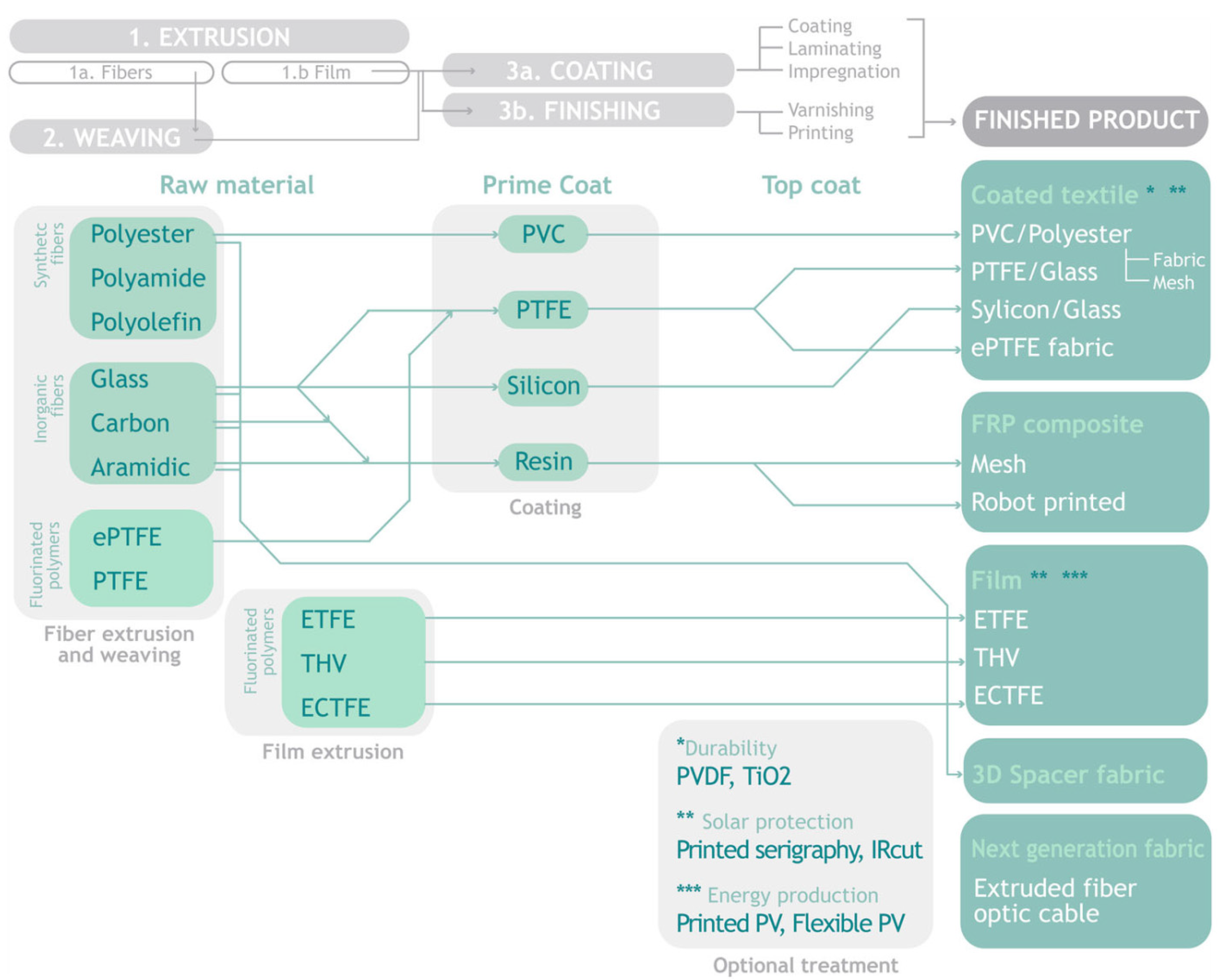
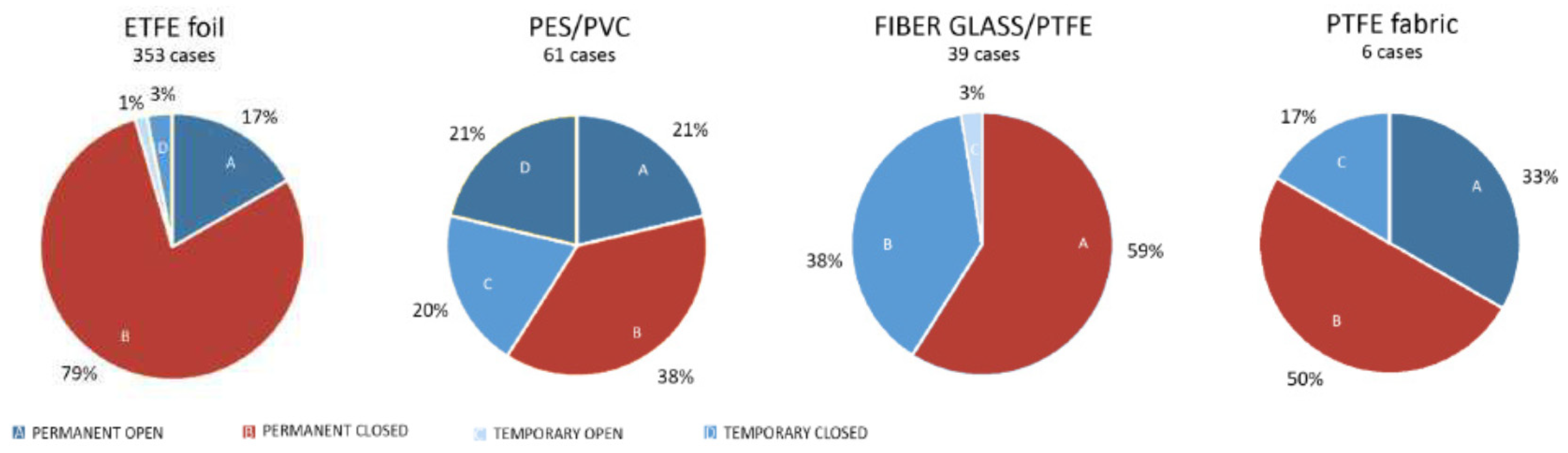
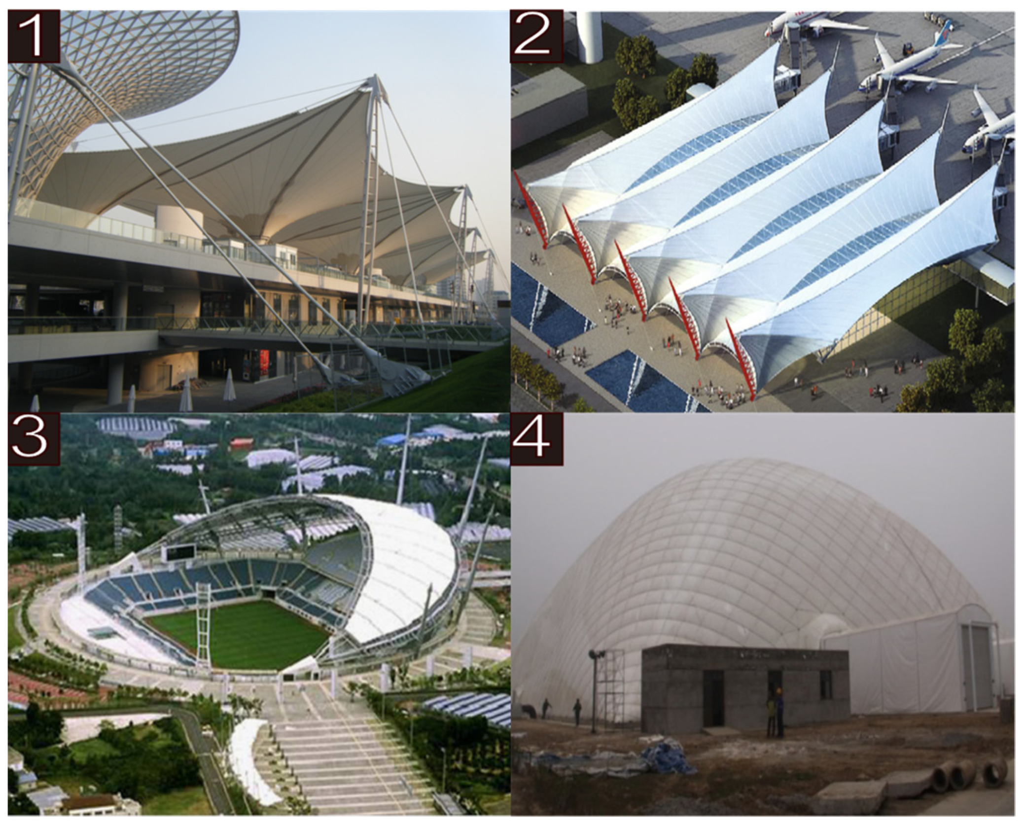
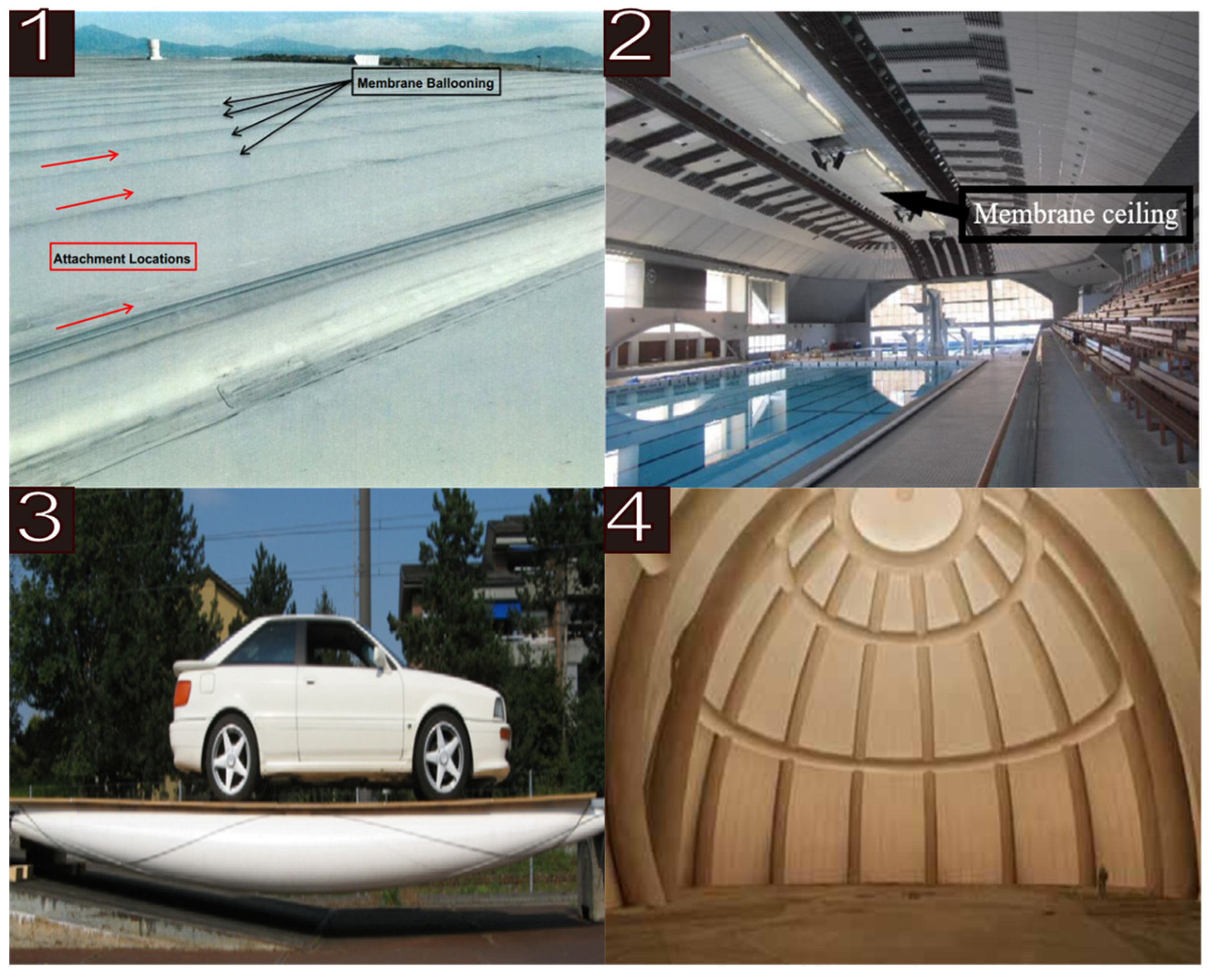
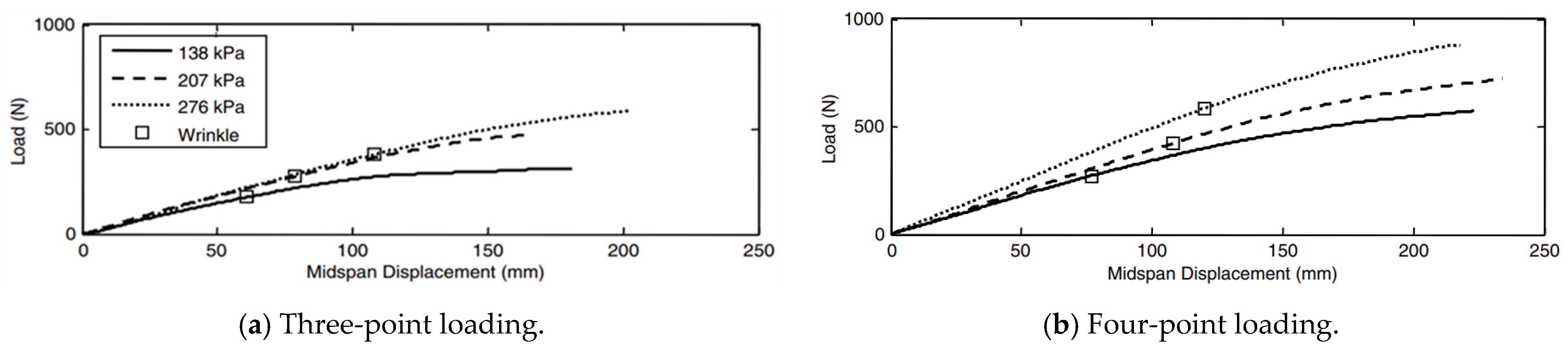
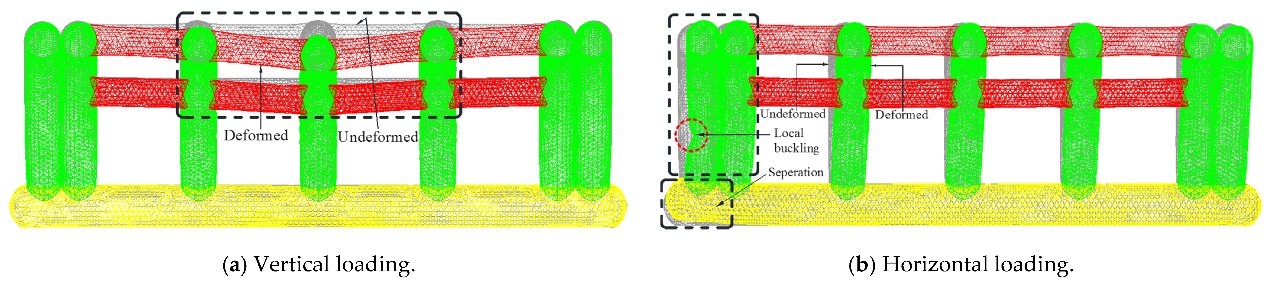
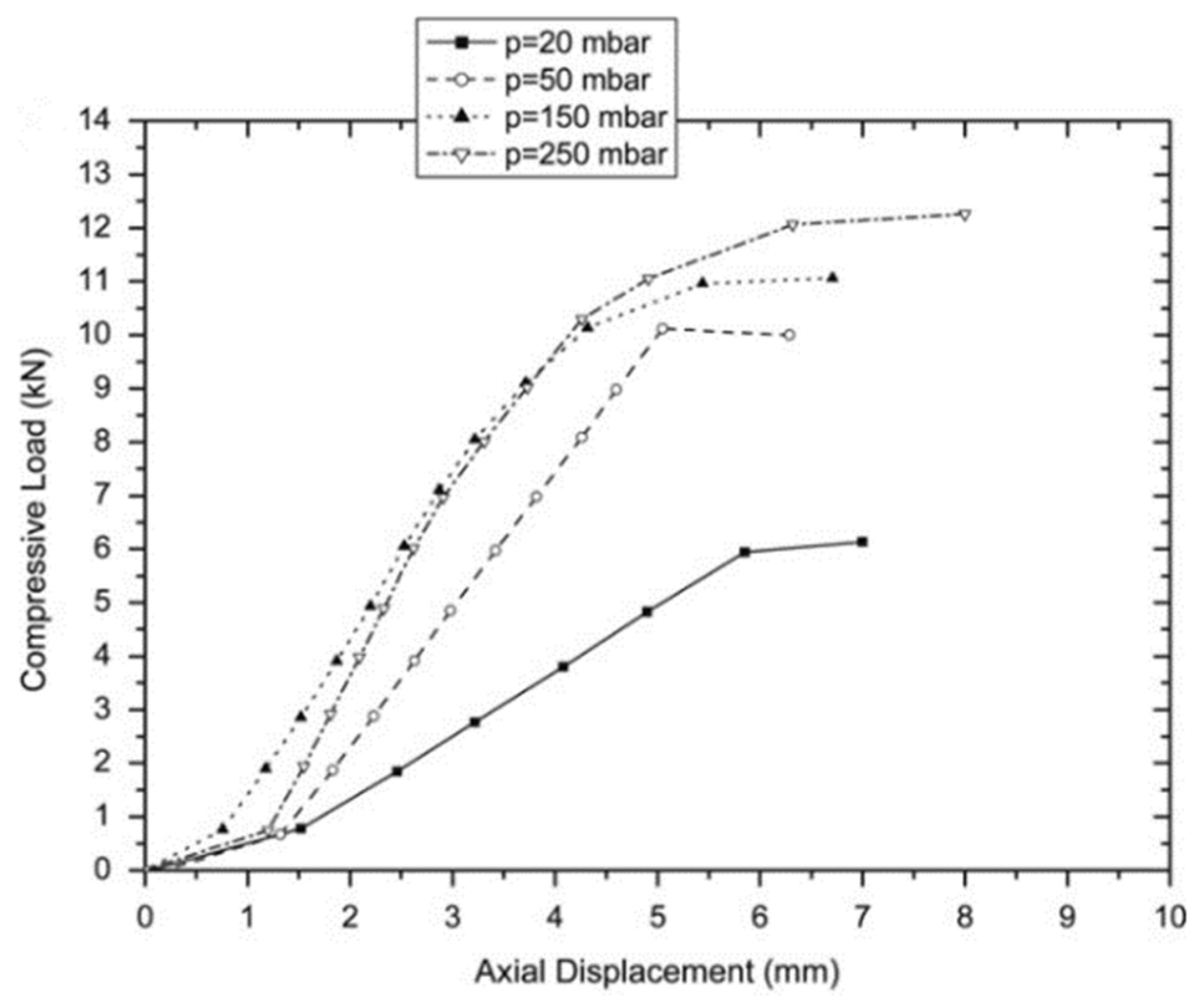
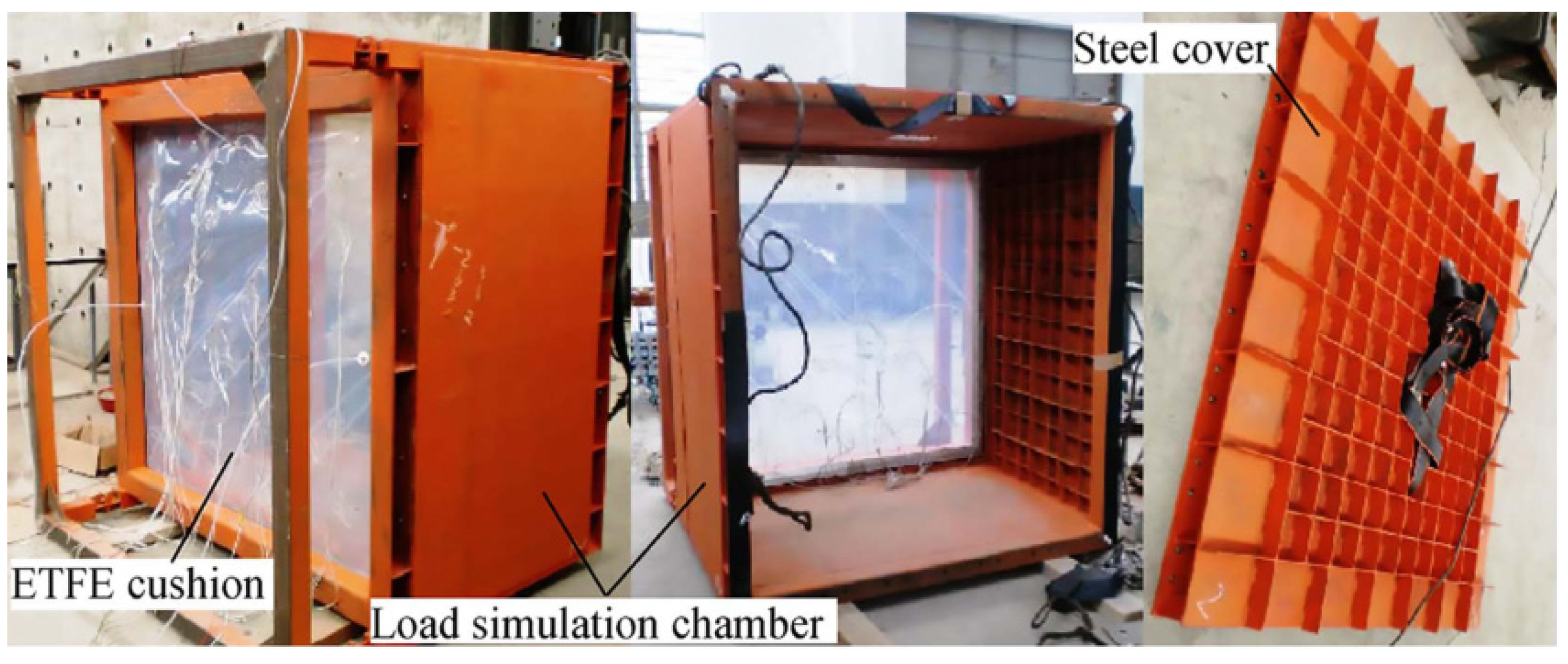
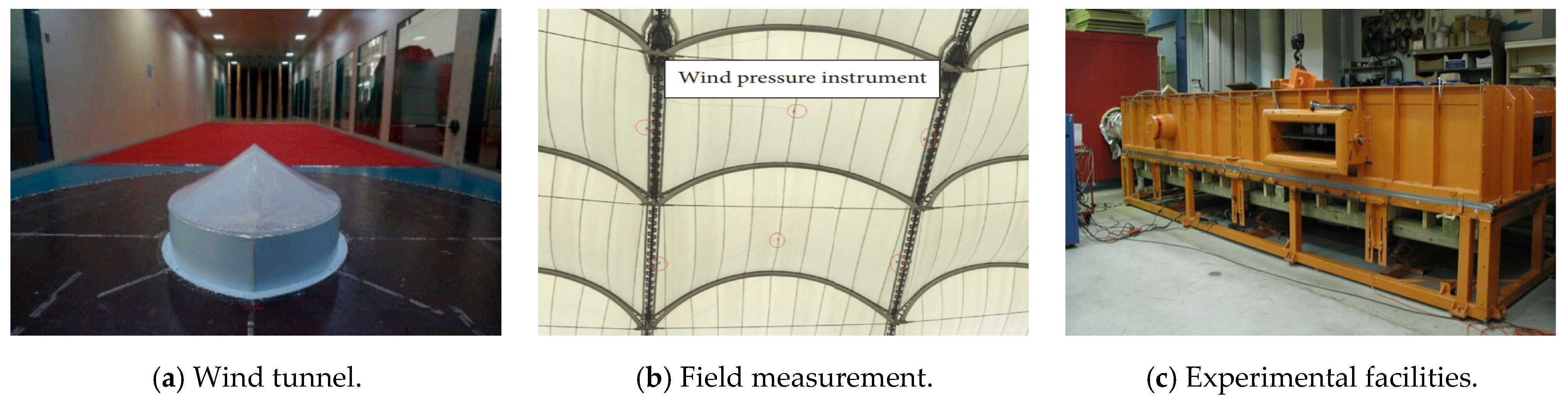
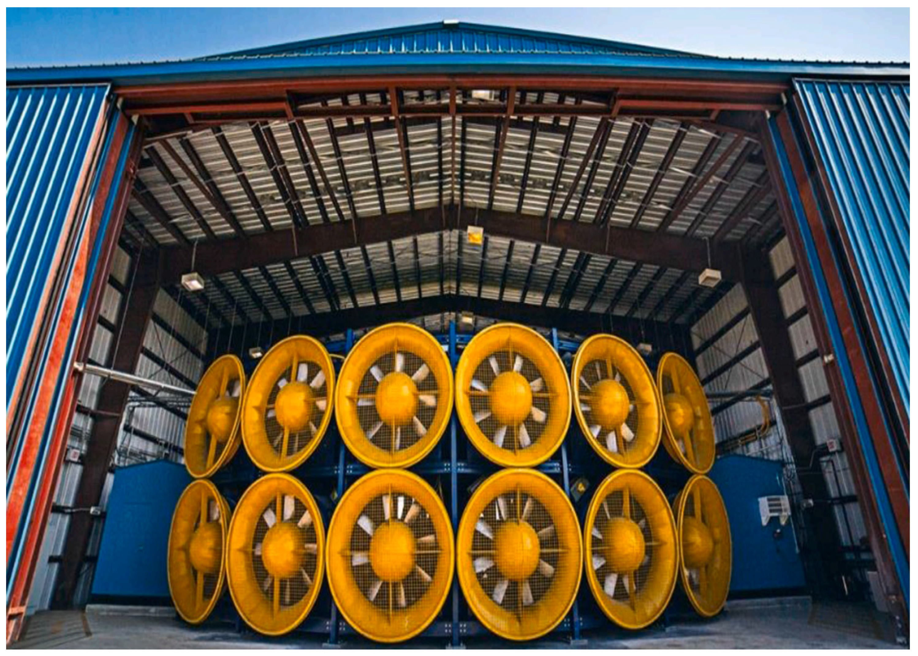
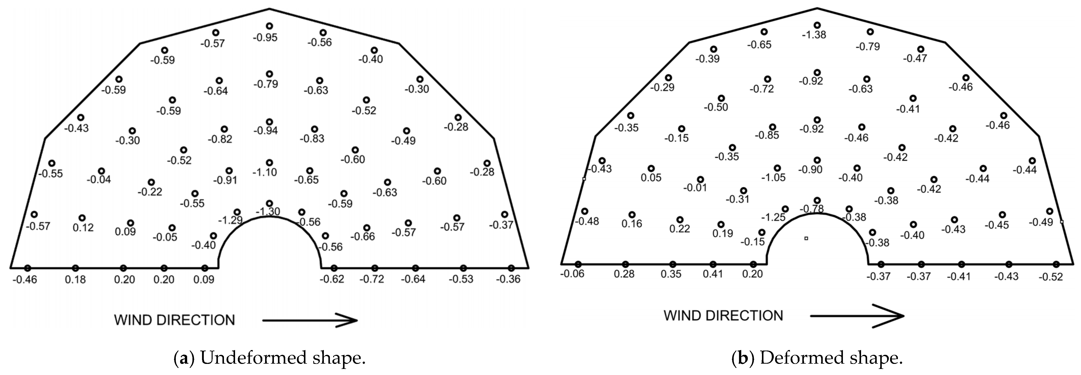
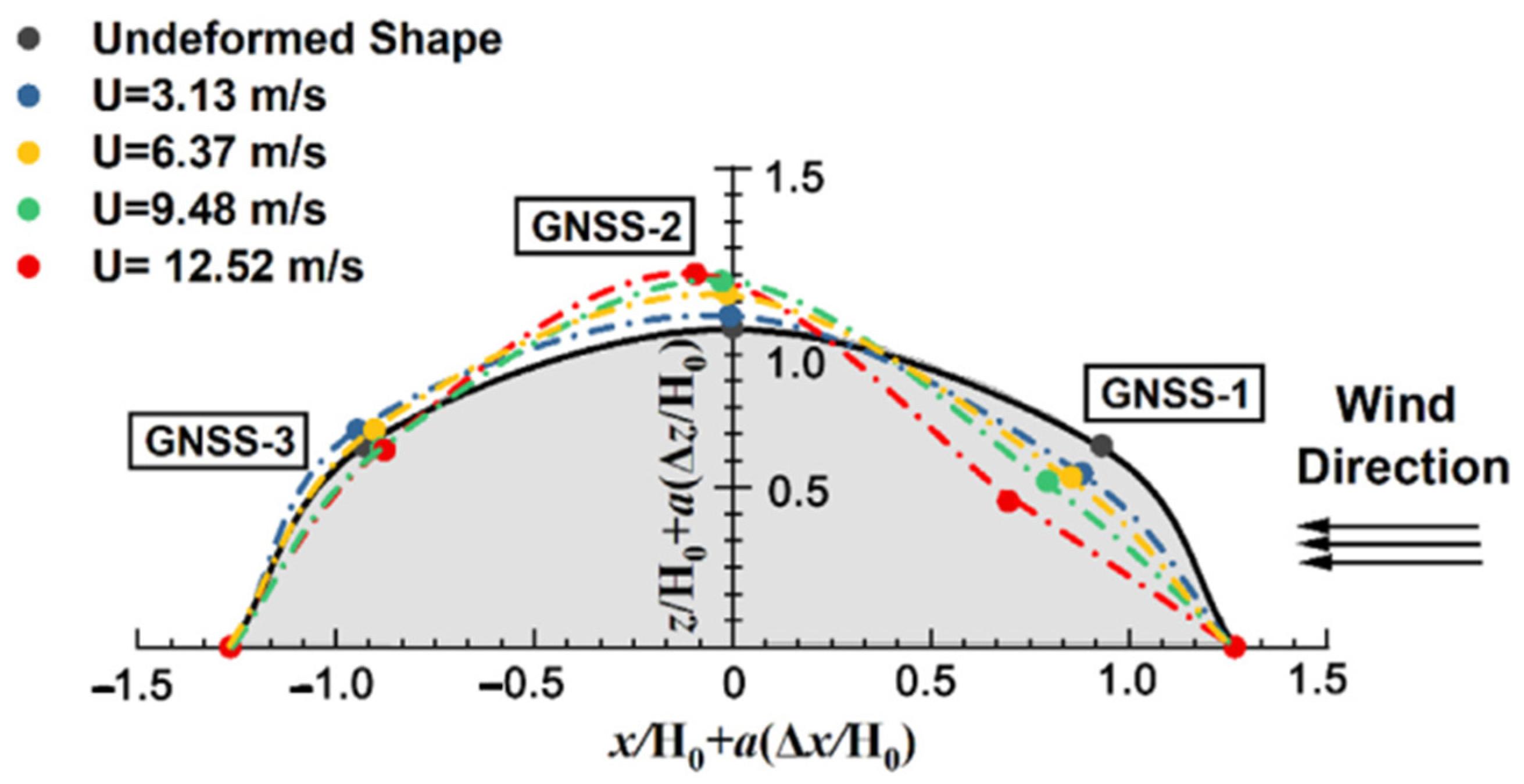
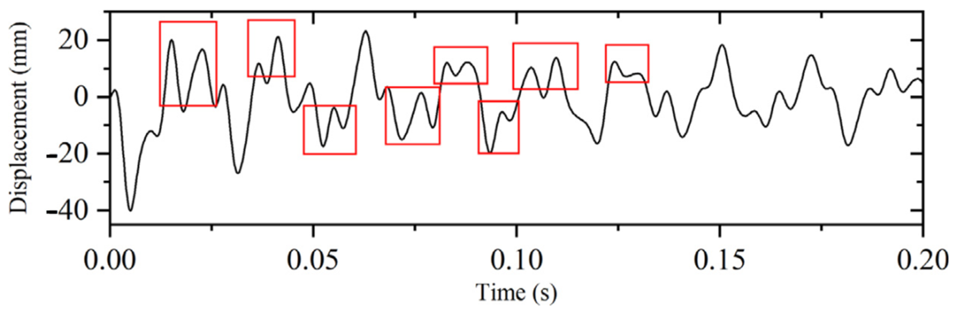
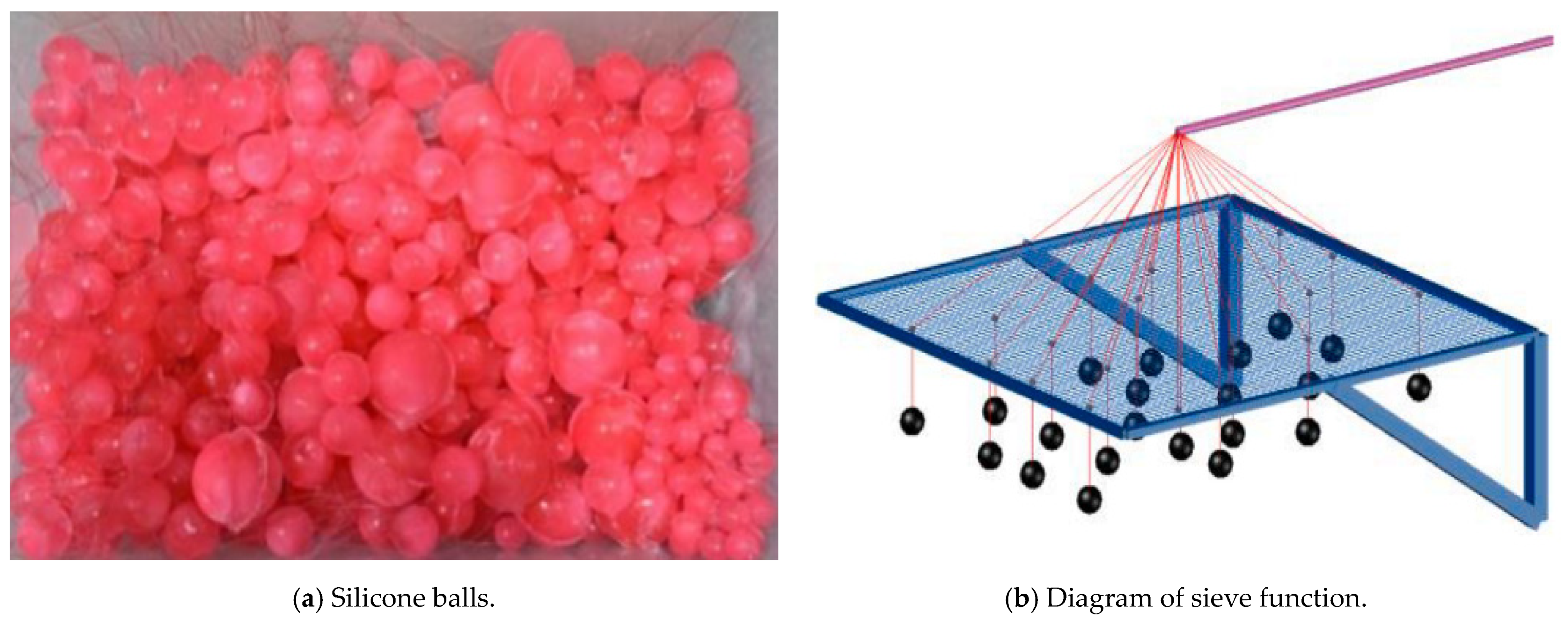
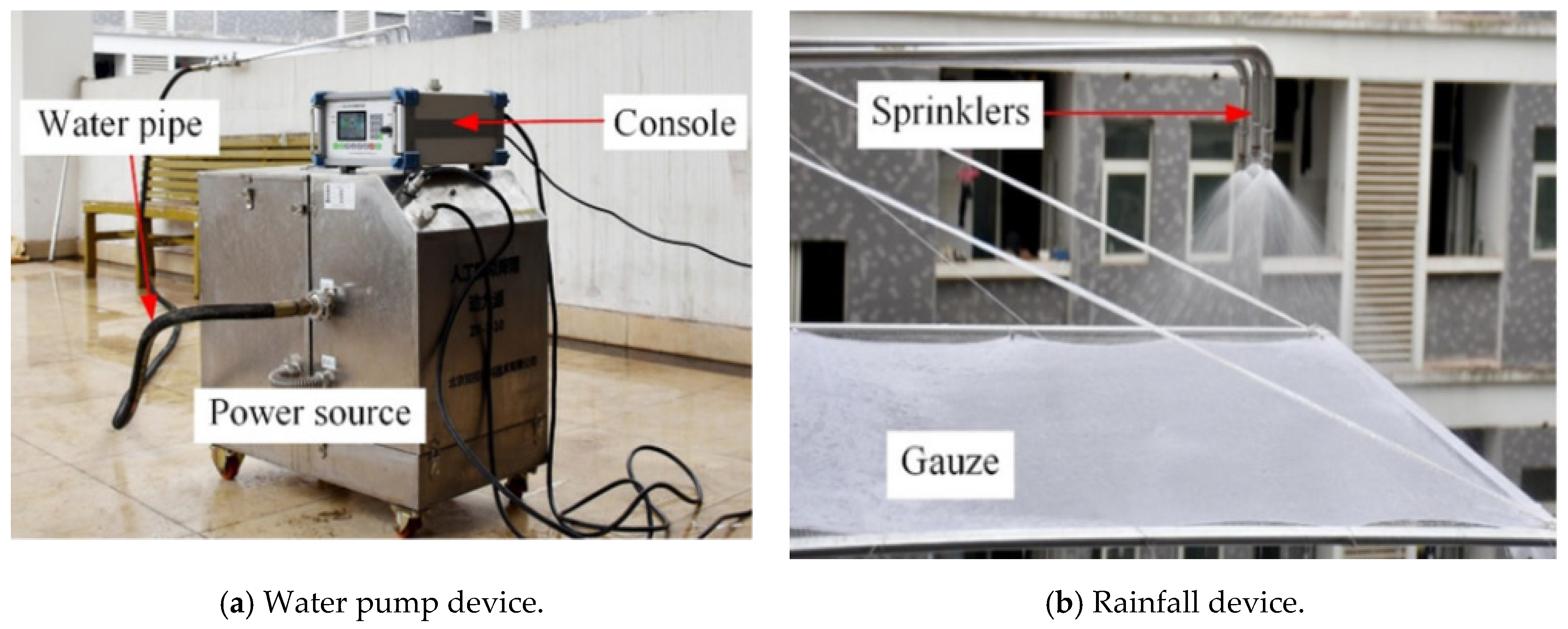
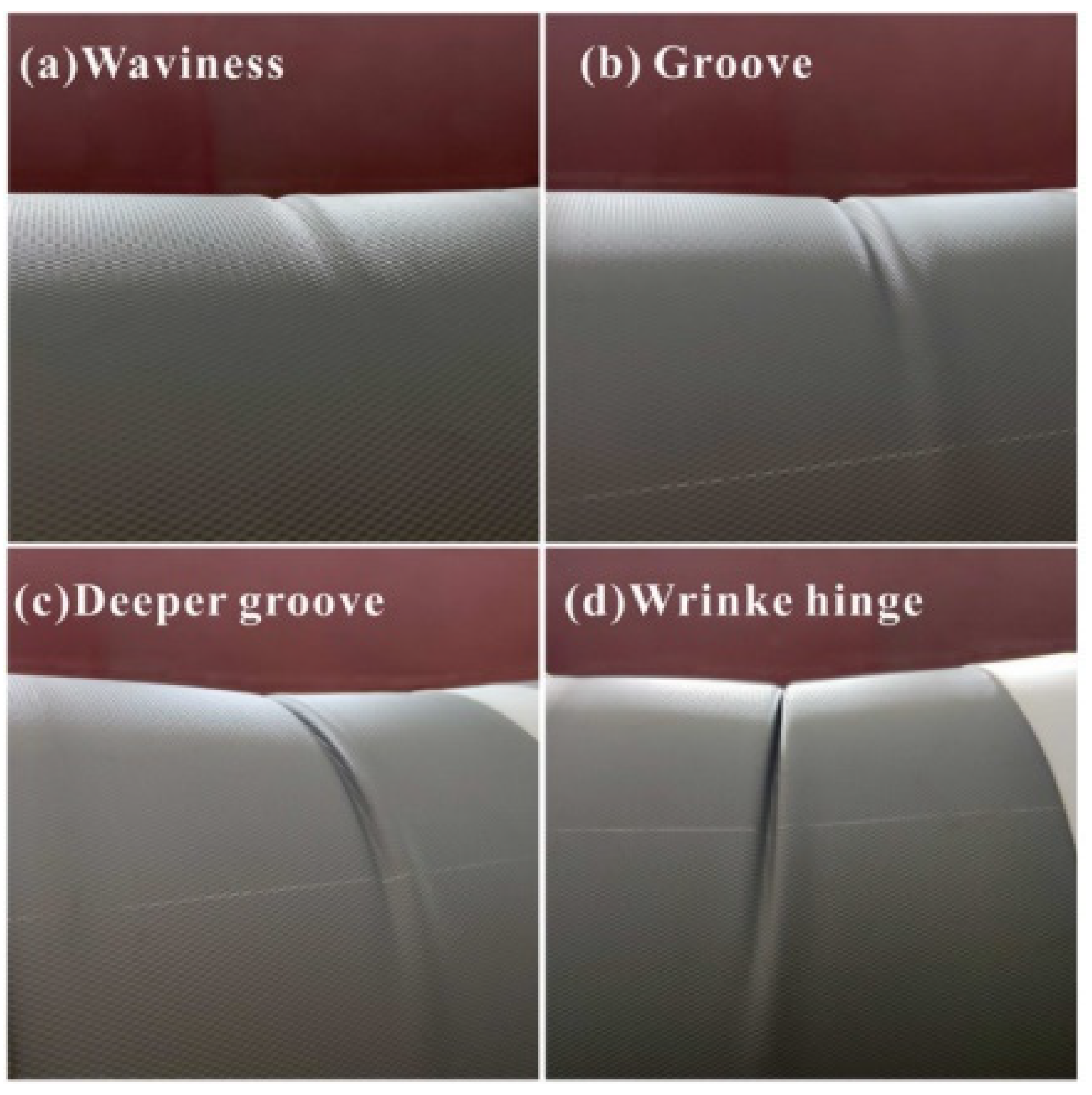
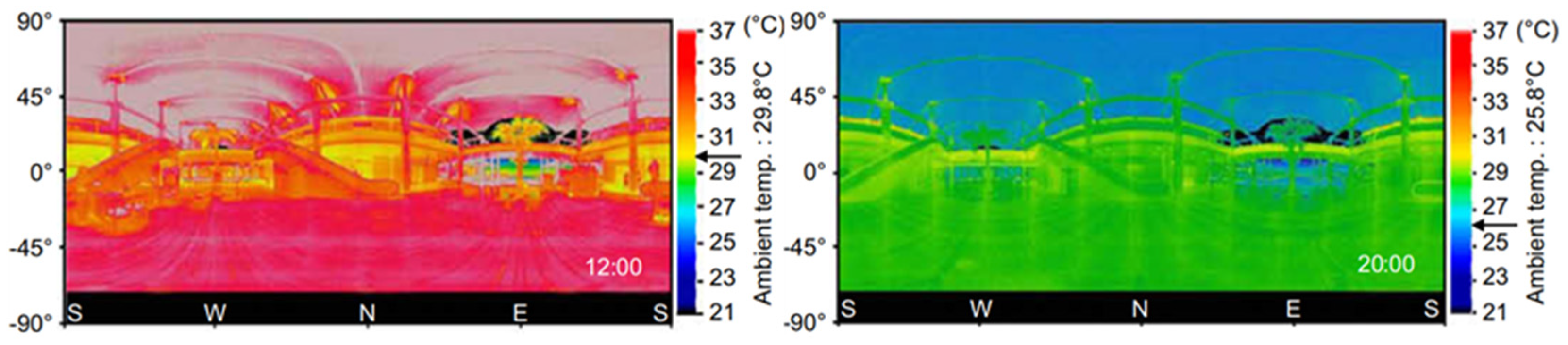
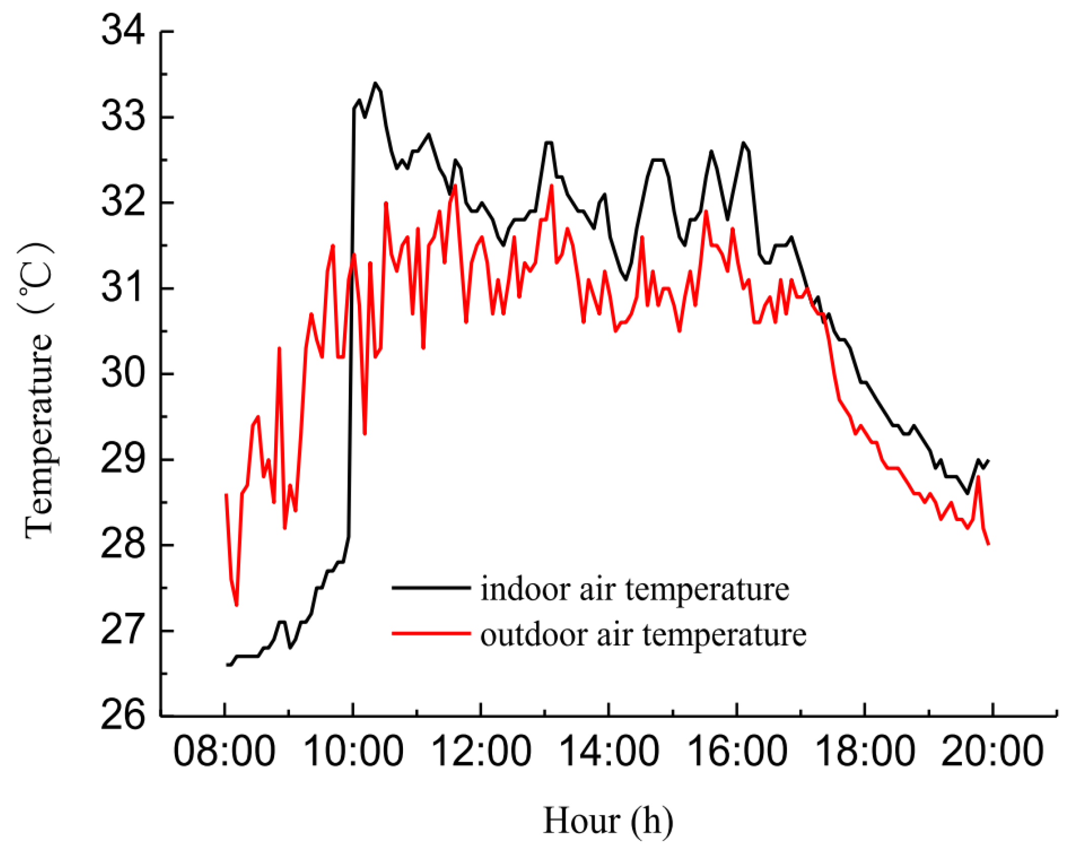
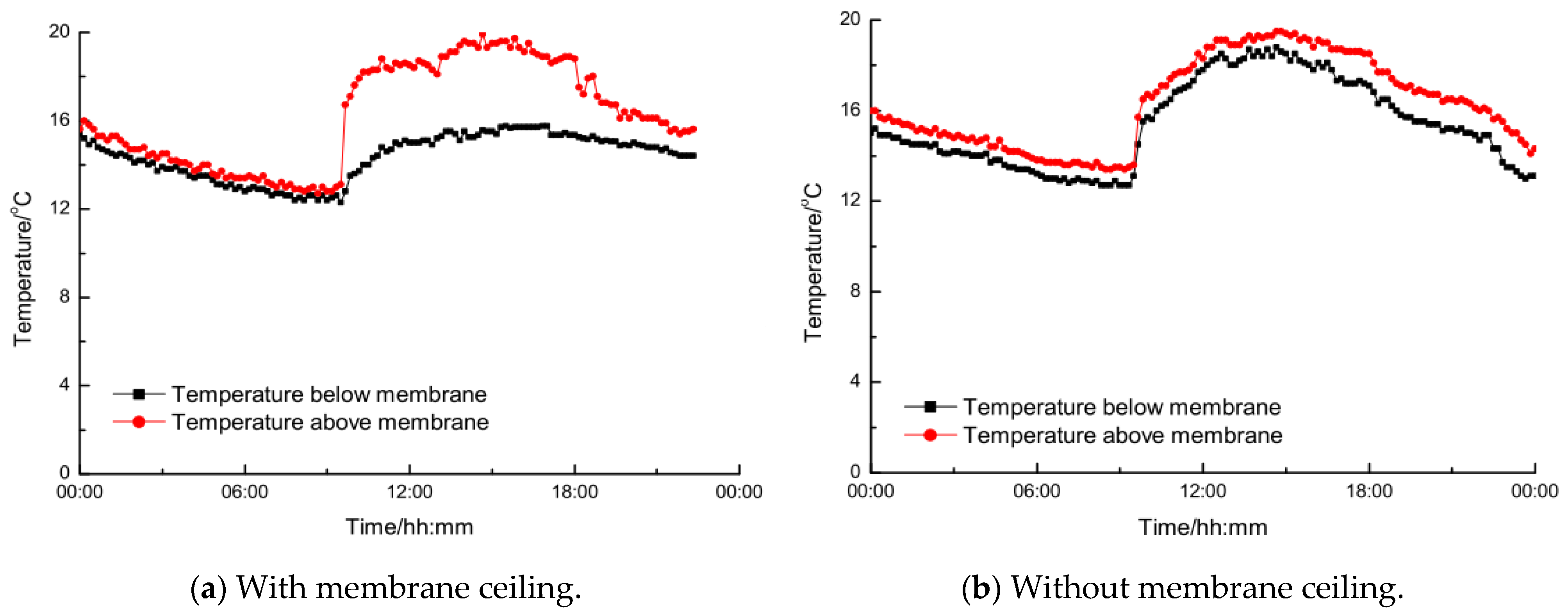
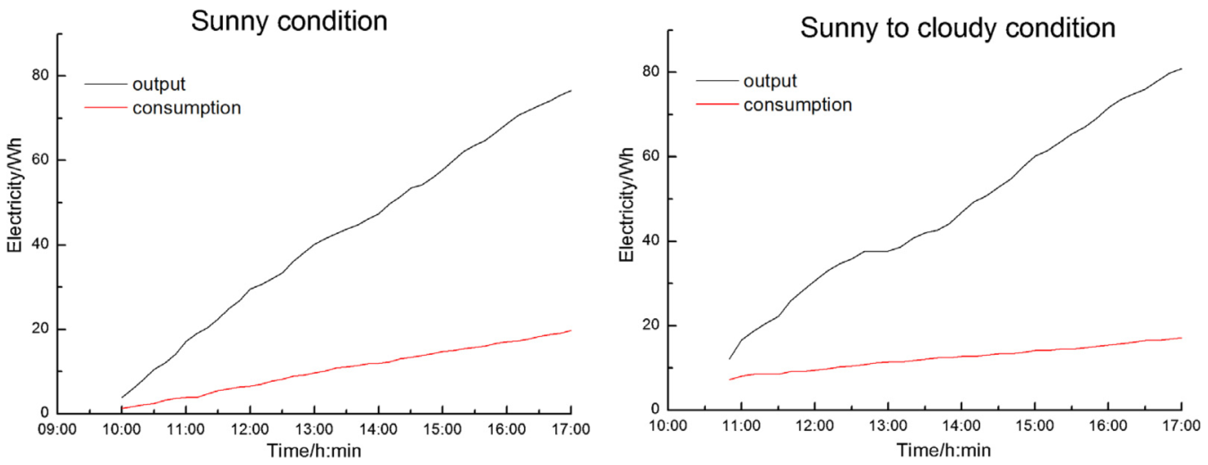
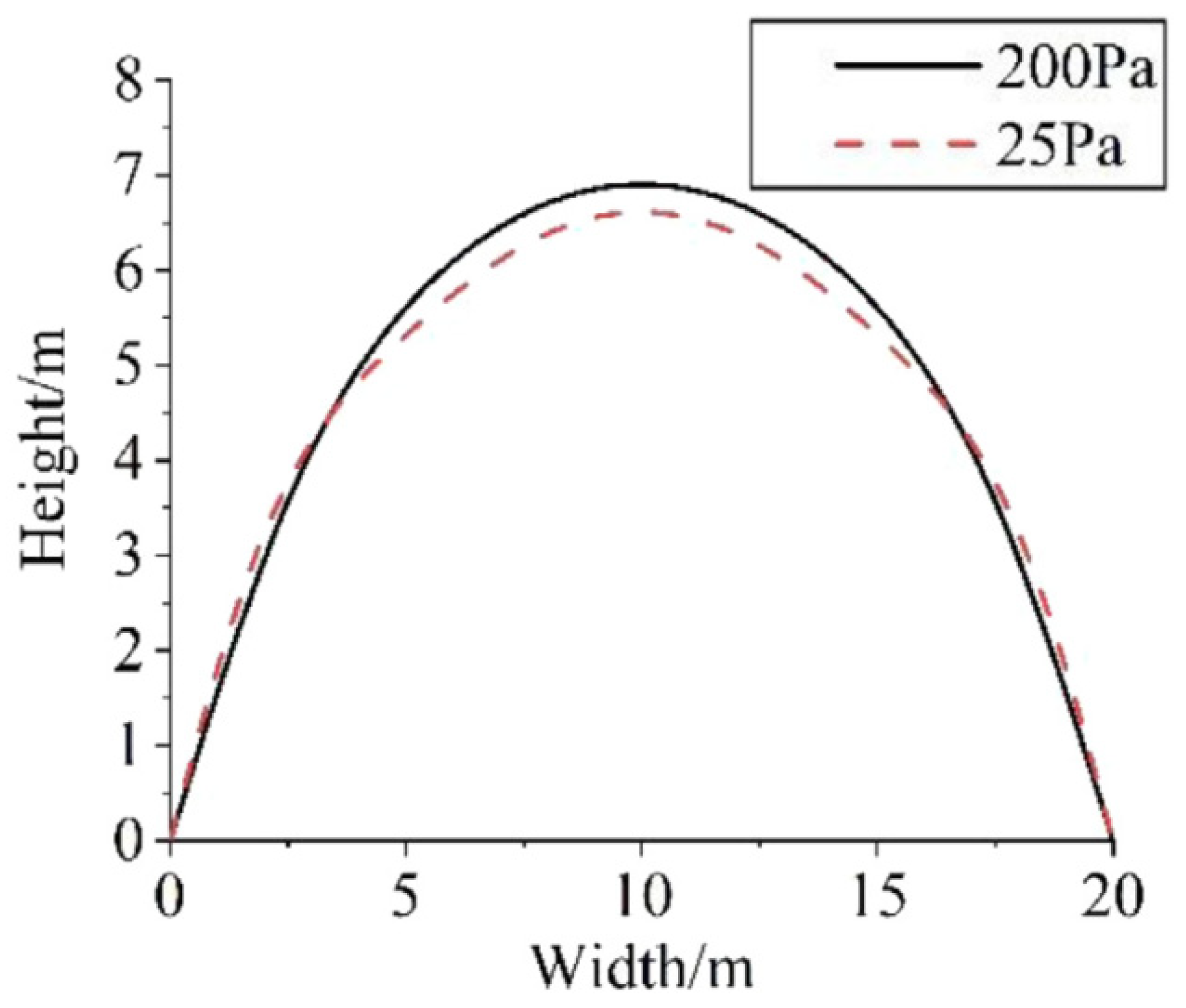
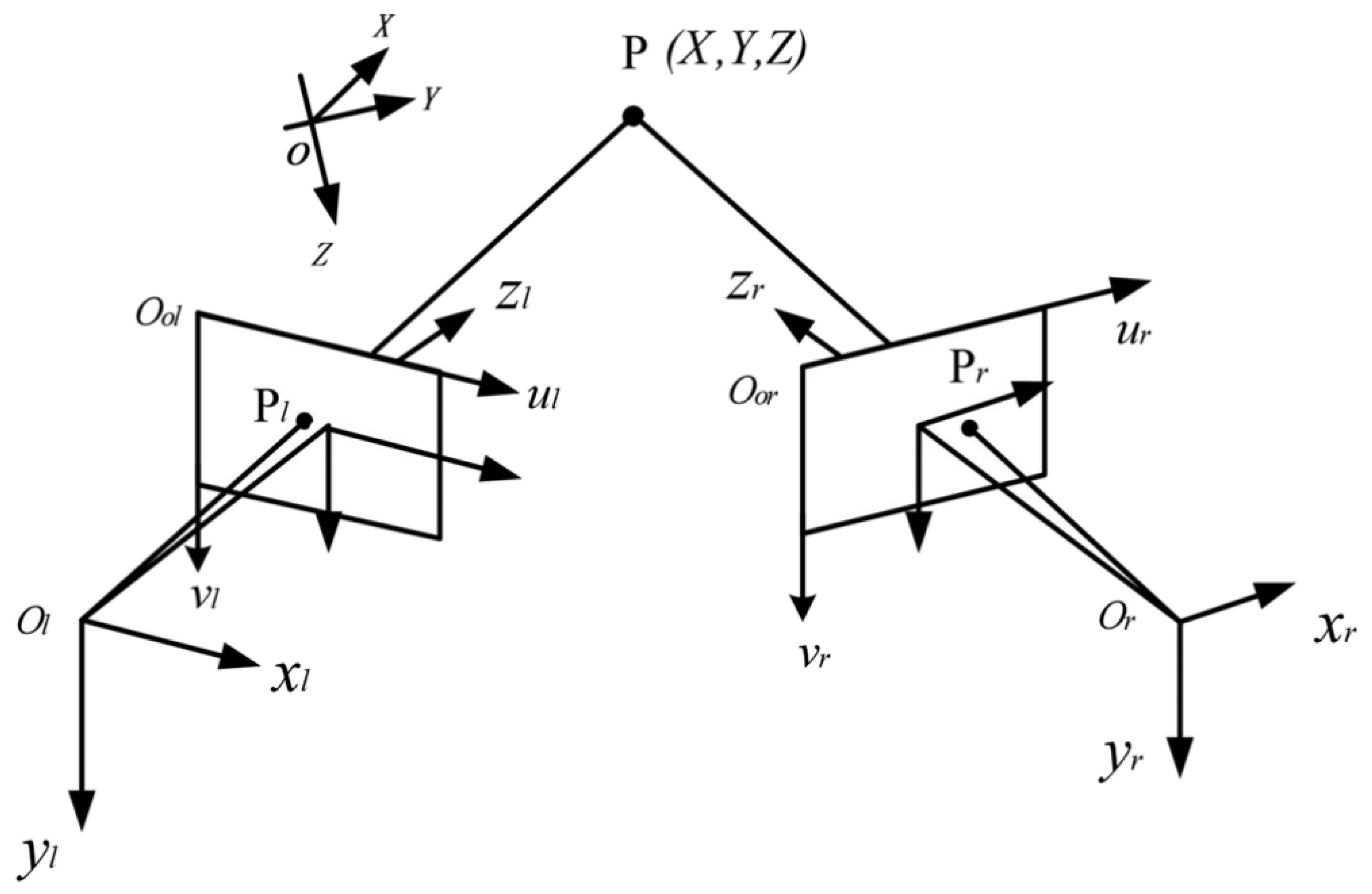
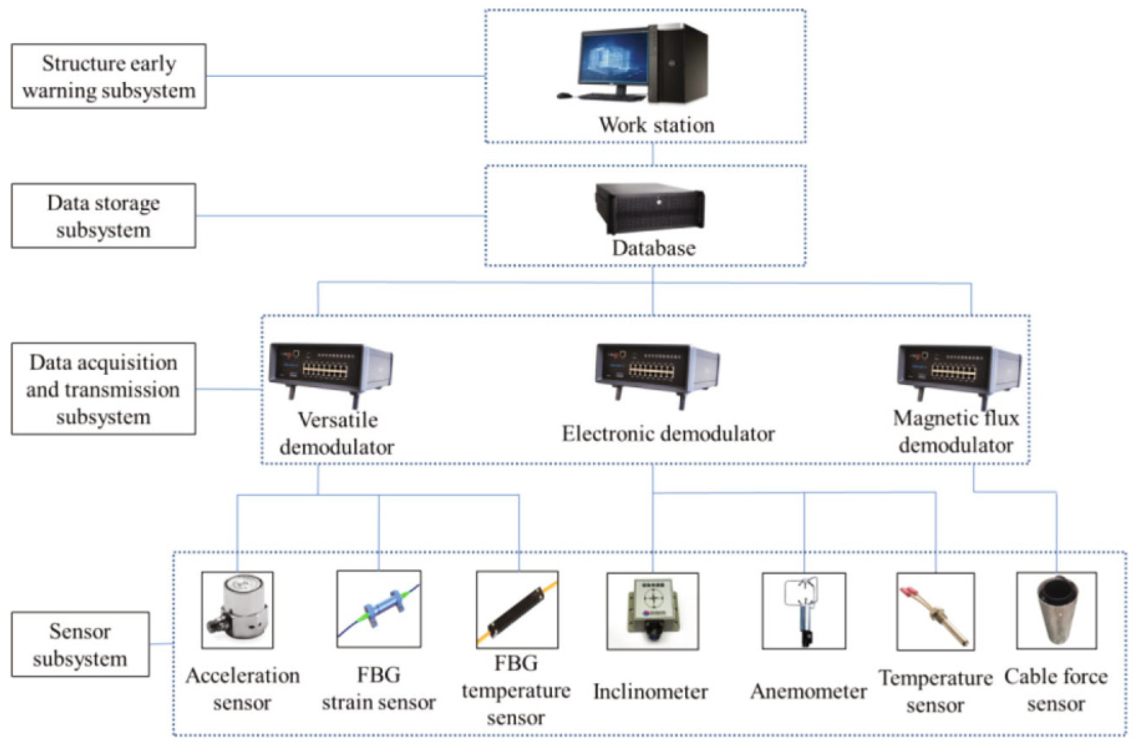
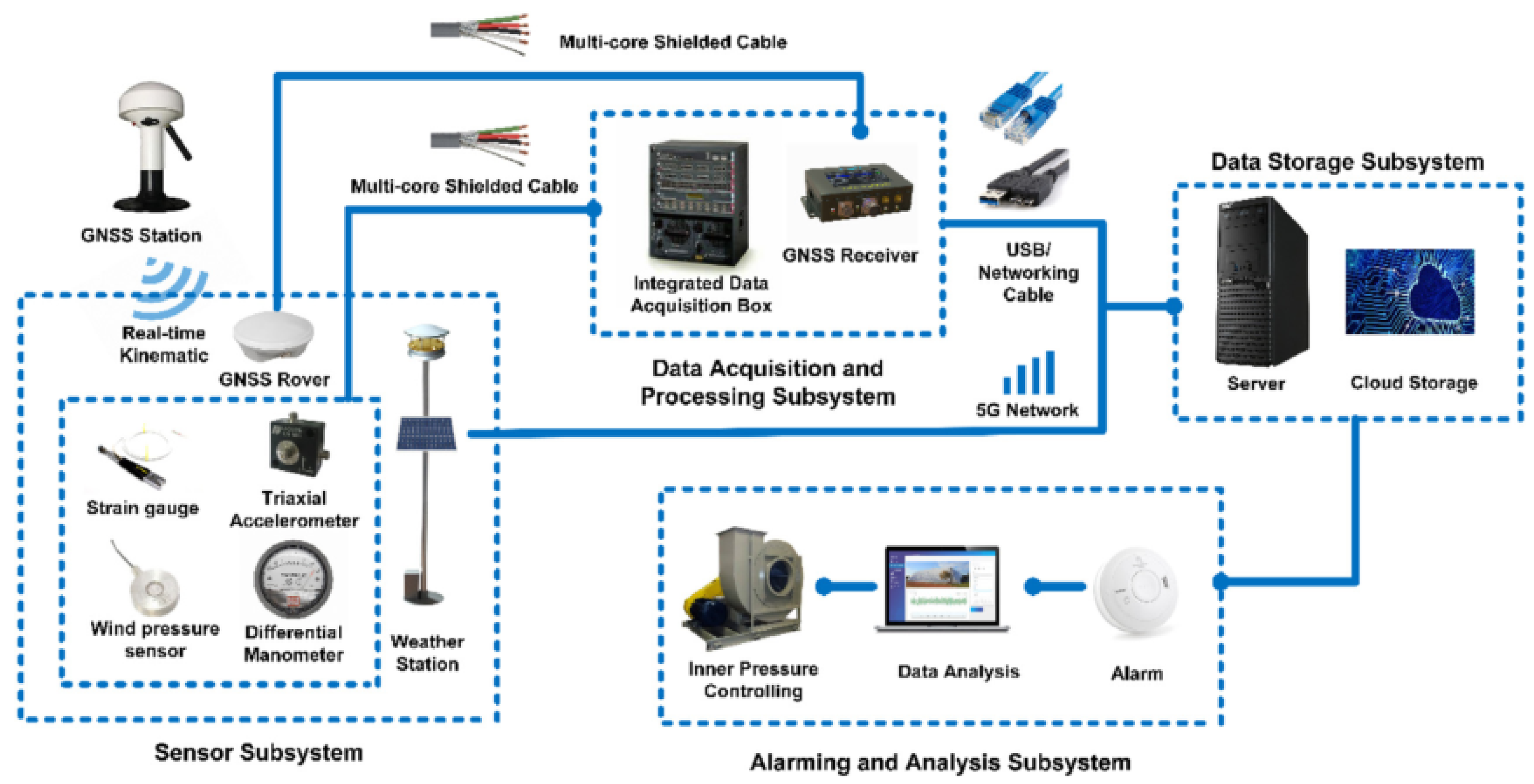
Figure 10.
NHERI Wall of Wind Experimental Facility [24].
Figure 10.
NHERI Wall of Wind Experimental Facility [24].

Figure 11.
Coefficients of pressure on the surface [30].
Figure 11.
Coefficients of pressure on the surface [30].

Figure 12.
Structural deformation under different wind speeds (side view) [19].
Figure 12.
Structural deformation under different wind speeds (side view) [19].

Figure 13.
Time course curve of tensioned membrane displacement affected by impact loading [82].
Figure 13.
Time course curve of tensioned membrane displacement affected by impact loading [82].

Figure 14.
Experimental equipment for hail effect [75].
Figure 14.
Experimental equipment for hail effect [75].

Figure 15.
Artificial rainfall device [87].
Figure 15.
Artificial rainfall device [87].

Figure 16.
Development of wrinkles [94].
Figure 16.
Development of wrinkles [94].

Figure 17.
Thermography of the environment inside the structure [100].
Figure 17.
Thermography of the environment inside the structure [100].

Figure 18.
Indoor and outdoor temperature variation time course [110].
Figure 18.
Indoor and outdoor temperature variation time course [110].

Figure 19.
Temperature fluctuating with time [6].
Figure 19.
Temperature fluctuating with time [6].

Figure 20.
Effect of weather on the energy output and consumption of an air cushion combined with PV panels [118].
Figure 20.
Effect of weather on the energy output and consumption of an air cushion combined with PV panels [118].

Figure 21.
The early stage of deflation structural profile [122].
Figure 21.
The early stage of deflation structural profile [122].

Figure 22.
Camera measurement principle [133].
Figure 22.
Camera measurement principle [133].

Figure 23.
The framework of the SHM system for the cable–membrane structure of Yueyang Airport, China [32].
Figure 23.
The framework of the SHM system for the cable–membrane structure of Yueyang Airport, China [32].

Figure 24.
SHM system framework for the air-supported membrane structure of Shanghai Jiao Tong University [19].
Figure 24.
SHM system framework for the air-supported membrane structure of Shanghai Jiao Tong University [19].

Publisher’s Note: MDPI stays neutral with regard to jurisdictional claims in published maps and institutional affiliations. |
© 2022 by the authors. Licensee MDPI, Basel, Switzerland. This article is an open access article distributed under the terms and conditions of the Creative Commons Attribution (CC BY) license (https://creativecommons.org/licenses/by/4.0/).
Share and Cite
MDPI and ACS Style
Huang, H.; Li, X.; Xue, S.; Luo, Y.; Shi, D.; Hou, X.; Liu, Y.; Li, N. Performance and Measurement Devices for Membrane Buildings in Civil Engineering: A Review. Appl. Sci. 2022, 12, 8648. https://doi.org/10.3390/app12178648
AMA Style
Huang H, Li X, Xue S, Luo Y, Shi D, Hou X, Liu Y, Li N. Performance and Measurement Devices for Membrane Buildings in Civil Engineering: A Review. Applied Sciences. 2022; 12(17):8648. https://doi.org/10.3390/app12178648
Chicago/Turabian StyleHuang, Haonan, Xiongyan Li, Suduo Xue, Yaozhi Luo, Da Shi, Xianghua Hou, Yiwei Liu, and Ning Li. 2022. "Performance and Measurement Devices for Membrane Buildings in Civil Engineering: A Review" Applied Sciences 12, no. 17: 8648. https://doi.org/10.3390/app12178648
Note that from the first issue of 2016, this journal uses article numbers instead of page numbers. See further details here.