1. Introduction
In the oil industry, artificial lift systems (ALSs) [
1] become the natural alternative when the inner pressure decreases in a mature oil well. Depending on the ALS, such as the hydraulic pumping, the fluid mixture extracted is composed of different volumes of phases as a complex mixture of oil, water, gas, and, sometimes, solid particles. When the phase separation is introduced in the continuous process, separators work typically based on either gravity or centrifugal segregation through vertical, horizontal, as well as spherical configurations [
2], and commonly for the gas–liquid segregation [
3]. Other separation mechanisms such as impaction or electromotive force are also used for specific mixtures [
4]; a comparison of multiple methods as absorption and membrane separation for gas–liquid mixture is studied in [
5].
A separator could be implemented in different locations along the stream column, but is typically defined with horizontal configurations and complemented with additional inlet devices, as the helical separator, experimentally analyzed in for viscous fluids, and the so-called poor boy degasser, a vertical low-pressure loss device over two stages of separation, for gas and mud [
6]. For multiphase fluids, a three-phase gravity separator is very common, and its performance is influenced by its configuration, the flow pattern, the design pressures, and the complexity of the mixture. In the process, a pre-separation is performed in the inlet section by means of components such as as diverter plates, reversed pipes, dished heads, or cyclonic devices [
7]. For many oilfields, the separation of the phases from the mixture frequently involves emulsion and foaming into a horizontal separator without an inlet mechanism. This fact drives an improvement in gas separation, from the inlet device study. According to [
8], the cyclonic device might be more efficient than other devices; however, it has limiting factors as its sensitivity to small changes in flow and the large pressure required to generate the centrifugal effect. A recent gas separation strategy based on the cyclonic effect [
9] considers a numerical analysis for contours in velocity and pressure to set a mechanical configuration to deviate the gas. Though the cyclonic phenomenon is not explicitly addressed, in [
3], an inlet device producing centrifugal effects is used to separate wet gas in high-velocity conditions. An interesting computational fluid dynamics (CFD) analysis of the flow pattern is developed in [
10], where a mixture of gas is studied for different diplegs producing cyclonic dynamics. In [
11], the separation of a gas–liquid two-phase flow is modeled and analyzed with CFD tools by considering a cone as a cyclonic generator; also, the dynamics of a cyclone separator with helical fins is studied by CFD in [
12]. In [
13], the cyclonic phenomenon is also studied for an absorption separator of ammonia from a liquid solution.
An innovative horizontal separator is designed with inclined pipelines [
14], reducing the liquid at the top, but depending on the dynamics conditions such as the velocity and amount of liquid in the mixture. On the other hand, a static mixer is a device to homogenize the particle distribution into size scales, depending on the nature of the mixture [
15,
16]. However, for a mixture with a high concentration of gas, the density difference of the phases makes the static mixer fail in mixing; in this case, an interesting dynamics is produced, which favors the separation of gas [
17]. In other research fields such as boiling flow fields, separation devices such as the one studied in this paper might be helpful [
18], mainly for heat transfer enhancement and liquid evaporation models over the boiling temperature.
In general, the inlet section in a horizontal separator can provide a momentum degradation and promote a phase distribution, being a critical phase in the global separation process. Inlet devices, then, are critical to be designed in order to control that momentum absorption, and they might be selected depending on the application. Splash and diverter plates, for example, manage foam generation and could be useful for mixtures with a high gas concentration. The pipe distribution must deal with the amount of liquid and velocities, and helical devices must manage the pressure drop. However, having established the essential dynamics factors from a given application, the latter is regarded to be designed in gas separation in this study.
Therefore, motivated by a real application in the Gulf of Mexico by Nuvoil corporation for oil extraction, using the jet-pump ALS, the main contributions of this work are summarized as follows:
The study of a commercial KMS static mixer for the same effect as a helical separator to be physically implemented as the inlet device for gas separation in scenarios with non-fixed fluid properties and dynamics parameter variations as incoming velocities and different phase distributions in the mixture.
Commonly, numerical and theoretical studies are reported in the literature with minimal experimental implementation. In this work, the inlet device is designed according to the fluid properties, and dynamics conditions are evaluated for the gas reduction in a scaled laboratory prototype to respond to a real application in oil fields.
The multiphase mixture flowing through a KMS is experimentally studied to verify the gas reduction, contributing both defoaming in a scaled separation reservoir and an improvement of the injection pump efficiency into an ALS process.
The effect of gas on the sedimentation time is also analyzed and, instead, is a specific design of the device.
In this work, numerical results allow for the physical configuration of the KMS to be determined under different situations, compared to the case where it is not implemented, producing scenarios for decision-making in the oil industry.
The work is structured as follows. Preliminary considerations of a KMS static mixer are stated in
Section 2 to describe the main problem in
Section 3 as an improvement in the reduction of gas from a hydrocarbon mixture coming from an oil well. The strategy of separation in the process is proposed from basic experimental results; numerical studies are developed in order to verify the basic performance of the proposal, allowing some configurations for both single (
Section 4) and multiphase (
Section 5) cases to define the physical implementation, which, as a complement to the experimental analysis in
Section 6, is developed with a focus on the effect of the KMS on the reservoir according to the effect of the gas separation reduction. Finally, some general remarks are stated in
Section 7, and final conclusions and future work are presented in
Section 8.
2. KMS Static Mixer Preliminary Considerations
A static mixer was designed to generate a homogeneous mixture of miscible components without mobile pieces [
15]. Multiple geometries are described in [
19], where the K, G, R, and M mixers are studied for particular cases and fluid properties such as viscosity; however, it can be also used to produce phase dispersion, chemical reactions, and heat transfer, among other applications [
16]. It is verified in [
20,
21] that, with a gaseous component as a non-miscible phase in the mixture, the mixture fails and dispersion arises along the pipeline where the mixer is hosted. Then, it is possible to take advantage of this effect by producing a phase dispersion because of the tension between the phases. For KMS mixers, if the dispersion phase is a gas into a liquid, the densities’ difference and the produced centrifugal effect concentrate the lightest phase at the center of the pipe, while the heaviest is distributed towards the walls [
17].
Figure 1 shows the typical configuration of a KMS, used in this work. Along length
L, the mixer is composed by
n helical elements with diameter
D and length l with relation
, discontinuously connected by an angle
and walls with a torsion angle
[
16].
For the jet-pump ALS, by using the KMS as the inlet device, it is imperative to define a minimum pressure drop in the horizontal separator to ensure the extraction of water as the power fluid for the injection pump. With a KMS, the drop in pressure
is then calculated as [
16]
where
is the drop coefficient for static mixers in turbulent flow (
) with the Fanning factor
f defined as
,
being the mean density of the mixture;
v, is the velocity of the fluid;
, is the Reynolds number and
. The dynamics conditions of the fluid then determine the drop in pressure; however, the
n elements of the KMS should be set to avoid a low dispersion according to the coefficient of variation
[
16], defined as:
where
is the coefficient of the mixture, defined for a KMS mixer as
for turbulent flows. Notice that the phase dispersion becomes lower as
n increases, producing a high quality of the mixture.
3. Problem Statement and Methodology Overview
For a hydraulic ALS, one of the most common methods for separation in multiphase flows is the segregation by gravity by means of horizontal three-phase separators. As expected and since the process is applied into continuous flow, the separation could be inefficient without adequate equipment, particularly for those oil wells from which the extracted mixture has a high gas composition and foaming becomes an important challenge to deal with. The conventional three-phase separator, even without inlet devices, is quite enough for those oil wells where the gas concentration is not significant, achieving an acceptable performance in the separation of phases and recycling the water as the power fluid. Depending on the oil well, the concentration of the gaseous phase is an important parameter that impacts not only the separation, but also the efficiency in pumping; if the gas is not segregated from the water inside the horizontal separator, the electric pump to reinject the motor fluid into the oil well demands more energy.
The focus of this work is two-fold: the first objective is the study of a KMS mixer as the inlet device to favor the gas reduction just before the multiphase mixture enters the horizontal separator; the second objective of the study is focused on the experimental analysis of the sedimentation times of the phases in the reservoir of the separator as a result of the remaining gas in the reservoir. Although the KMS was originally designed to generate a homogeneous mixture of miscible phases, for an incoming fluid with a high difference in density such as a liquid and gas, the mixer does not operate as expected, and the helical acceleration sends the liquid to the wall of the pipe. while the gas, the lightest component, remains at the center of the tube. The analysis performed in this work aims to characterize this phenomenon for determining the dynamics and geometric conditions for the implementation as a gas pre-separator in the oil extraction process. Once having defined these conditions, the dynamics of sedimentation is analyzed to describe the performance regarding the times and quality of the separation in the reservoir. The studies were developed in a scaled pilot platform where the KMS and the reservoir were assembled based on previous numerical analysis.
The cyclonic phenomenon produced by the KMS is exploited to isolate the gas by means of a deviation strategy that should be characterized in location and geometry in the vertical pipeline just before the entrance to the three-phase separator, as depicted in
Figure 2, to guarantee the casing of the concentrated gas.
The parameters to be determined from the study to take full advantage of the phenomenon are the diameter
of the inner gas deviation pipe once in the stable region of the cyclone, the distance
d where the KMS is located with respect to the deviation pipe allowing this capture, and the length
L of the KMS, which is defined by
n helical elements. Once the mixture is broken by the KMS, the gas should be guided to the output depicted in
Figure 2, while the heaviest phase at the walls ends at the bottom of the horizontal separator, where, by sedimentation, the oil is segregated from water over time.
The experimental performance is studied with the configuration from
Figure 2, where the pipeline is set as in the oilfield, with
mm. In the pilot experimental platform, a
pump supplies the mixture to the system, making the fluid pass through a 3D-printed KMS of either 4 or 2 elements with
and a reservoir as the horizontal gravity separator, where the remaining mixture is accumulated.
The induced cyclone phenomenon was captured by an endoscope full-HD camera with
pixels and 60 fps at the outlet section where the deviation pipe, with diameter
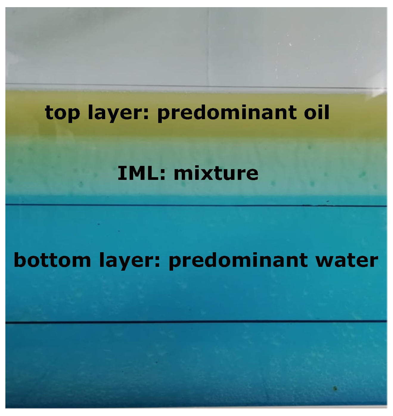
, to be defined, is located for casing the gas and deviating it. The behavior of fluids in the reservoir while filling was analyzed by means of another lateral camera of 30 fps, which captures the longitudinal section of the reservoir to identify the generated layers’ thickness, a slow dynamics with samples every 10 min, as described in
Section 6.
A particular real oil well application of the Mexican company Nuvoil suggests the drop in pressure of
Kg/cm
to maintain a continuous process of extraction of water from the horizontal separator by means of a triplex pump for injection at the surface. Then, according to the current pipelines at the surface, the number of elements
n becomes crucial for the configuration, not only for the pressure drop, but also for the required high dispersion, which impacts the reduced sedimentation times in the reservoir. Based on a mean production of 2500 bdp and streamline velocities’ measured samples from the company, it can be deduced from Equation (
1) that a 4-element KMS can produce a maximum pressure drop of
Kg/cm
, which, according to physical implementation in the field, yields a mean pressure of 8 Kg/cm
measured in the separator, enough to extract segregated liquids for the already described injection pump. A KMS with
elements was then studied as the inlet device by means of numerical simulations and validated with a laboratory experimental platform with controlled operational conditions, to define a solution for extended realistic cases.
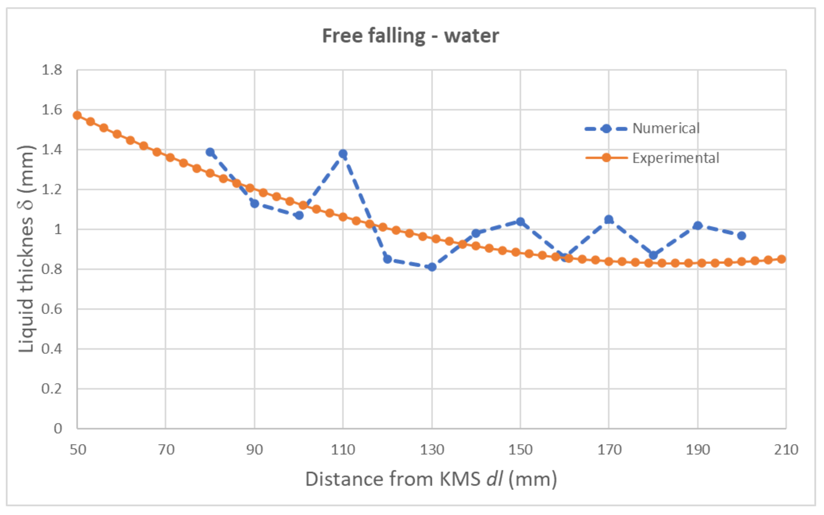
5. Multiphase Numerical Analysis
From the previous CFD configuration for the free-falling conditions, some additional simulations were tested including a mixture of water and oil (density
Kg/cm
and viscosity
), as well as added gas with the proportions as described in
Table 2 for different incoming velocities and volumes. The pressure at the output was set according to the one in the horizontal separator for the real process as
Kg/cm
. The only refinement of the numerical code consisted of a new sensitivity mesh analysis, resulting in a configuration of 3.5 million elements and a skewness of 0.81 for the same configuration parameters in
Table 1. Case 1 in
Table 2 corresponds to the configuration for water without gas, but only the accumulated air in the pipe before the liquid flows through the KMS. The velocity is defined as free-falling along 250 mm after the KMS.
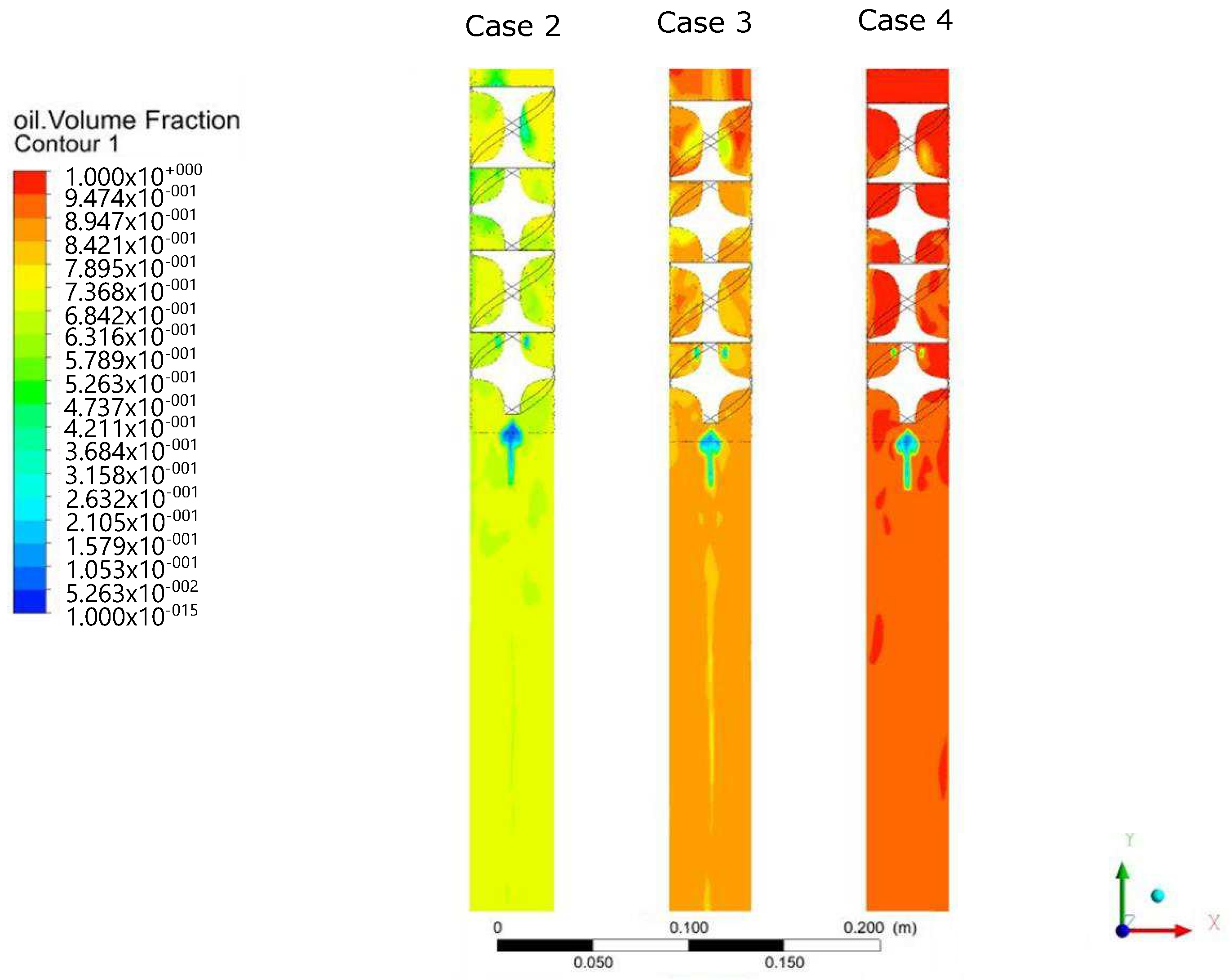
For Cases 2–4, the dynamics through the KMS is depicted in a transversal XY plane in
Figure 6 from the perspective of the oil phase at 10 seconds once the stationary regimen has been achieved. Notice that, since the configuration does not consider additional gas and the velocity is higher than the preliminary simulations, the KMS behaves as a pure mixer with a low dispersion for
regarding Equation (
2), and the mixture totally fills the pipe independently of the volume of phases in the liquid mixture. Though the KMS induces the centrifugal effect, the absence of a gas phase does not produce an evident adhesion of liquid on the pipe wall; however, the device produces a bubble of air at the bottom end of the KMS (
mm), from the air at the beginning of the simulation.
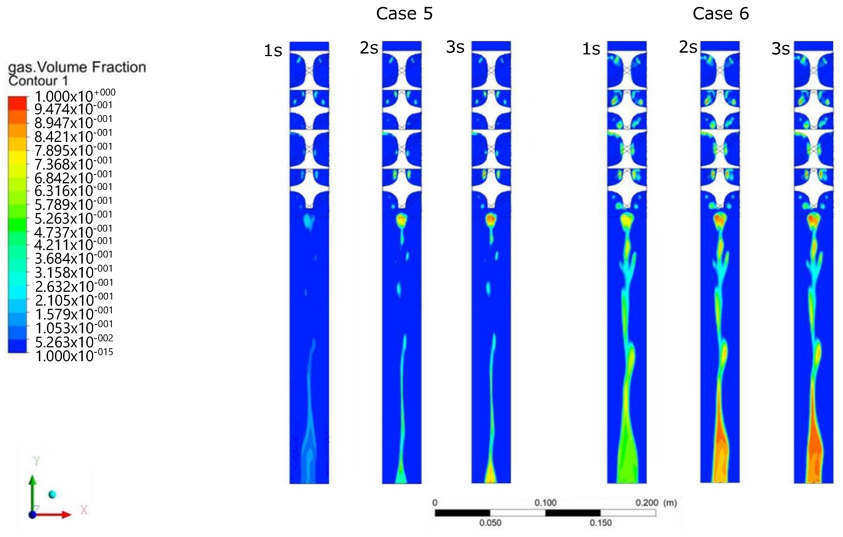
The cases with gas in the mixture are quite different, as expected, and proportions are motivated by data provided by Nuvoil from samples of the extracted mixture in a typical oil well where the jet-pump ALS is applied. Cases 5 and 6 are depicted in
Figure 7, where the gas becomes the lightest phase and becomes distributed at the center of the pipe. In the figure, three instances of the dynamics are depicted at
t = 1, 2, and 3 s after the entrance, and it can be observed that Case 6 has a more visible gas concentration since the gas phase in the mixture is higher. It can be noticed that at
t = 2 s and
t = 3 s, no significant changes are perceived, and an irregular gas concentration is obtained. In addition, according to
Figure 5, a preliminary stable concentration could be identified at
mm.
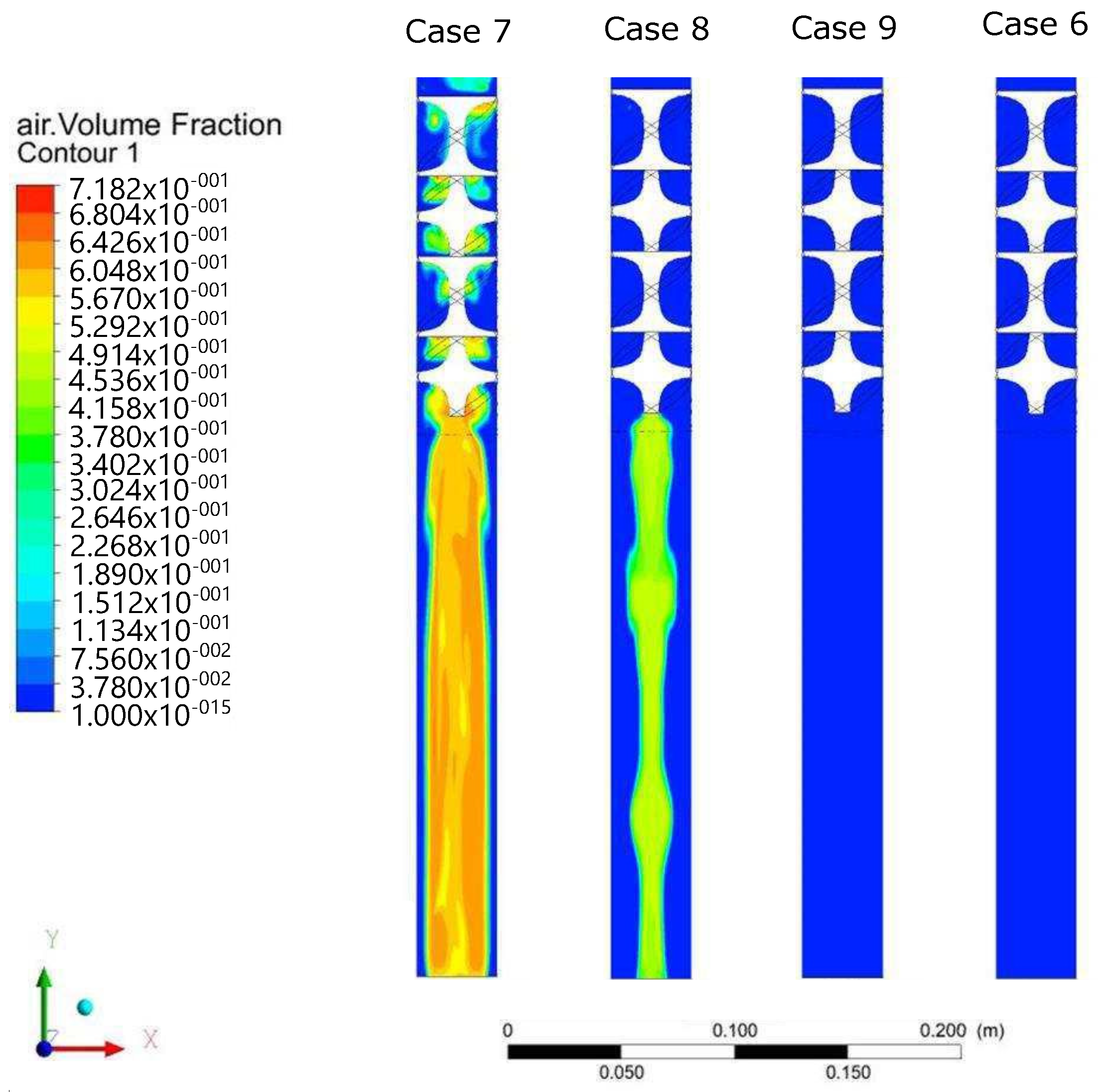
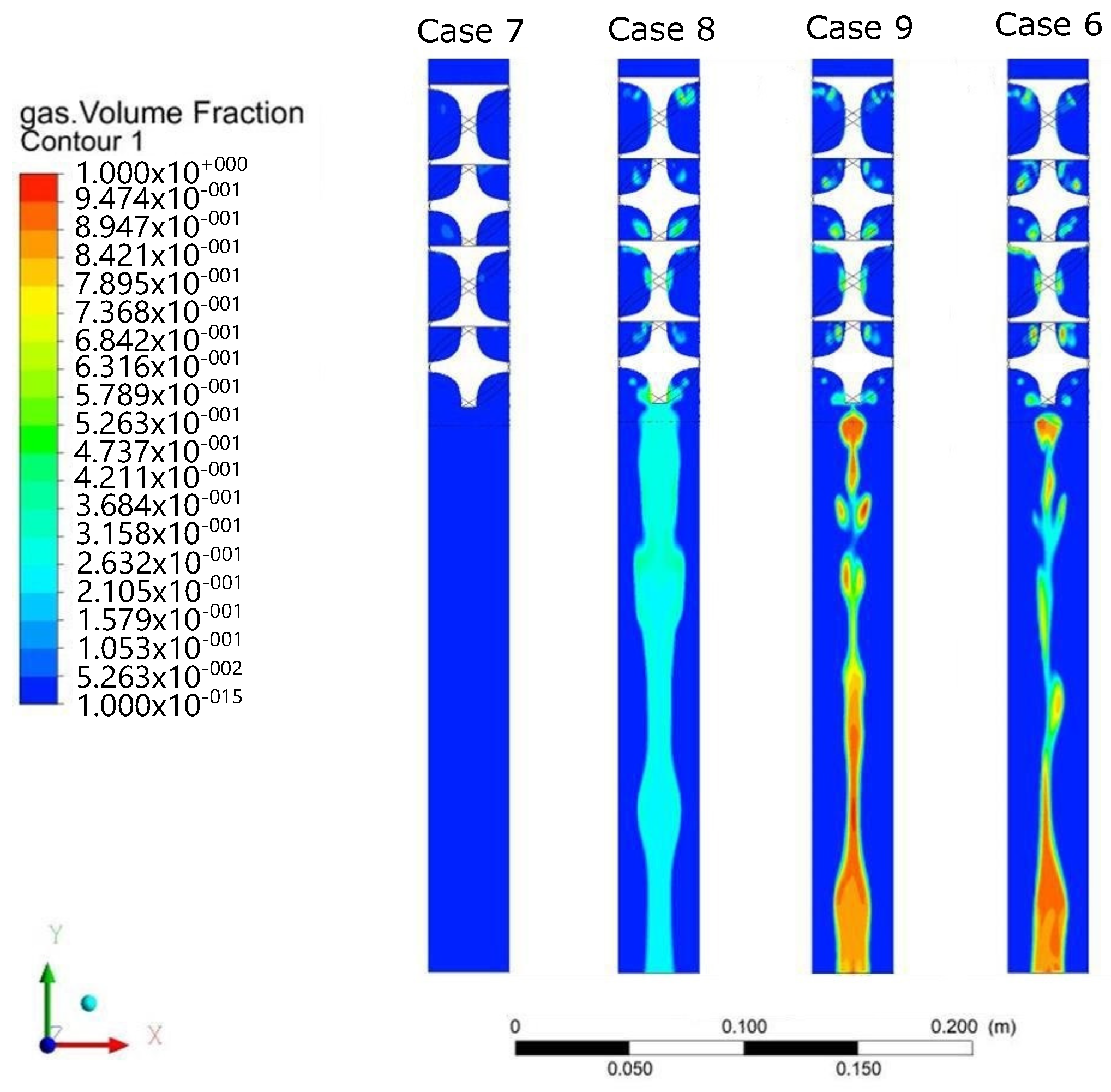
However, to verify the effect of velocity on the phenomenon, Cases 7–9 were analyzed with different conditions at
after the fluid entrance. In
Figure 8, the dynamics of air as the initial component in the pipe is shown, which, for the low velocity in Case 7, remains at the center while the liquid is in the wall, a similar result as Case 1. As the flow velocity increases (Cases 8, 9, and 6), the air is removed and replaced by gas, as depicted in
Figure 9.
Notice that, though the gas is distributed at the center with an irregular dispersion, a regular bubble of gas is always generated just at the bottom end of the KMS, which tends to flow while the mixture of oil and water is added to the walls.
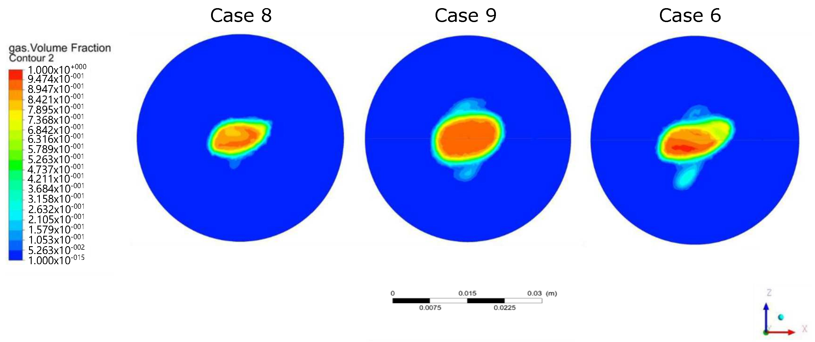
From these comparisons, it can be verified that, in general, there is a non-homogeneous concentration of gas at the center of the pipe, so that the thickness could not be considered regular as in the single phase, especially for higher velocities and the combined properties from different volumes of the fraction in the phases. However, an important characteristic that stands out from Cases 5–, is the gas concentration in a bubble just ending at the KMS, such that it could be cased to be canalized before it flows along the pipe. This bubble is formed approximately at
mm from the KMS and has a rotating geometry with a mean diameter, as depicted in
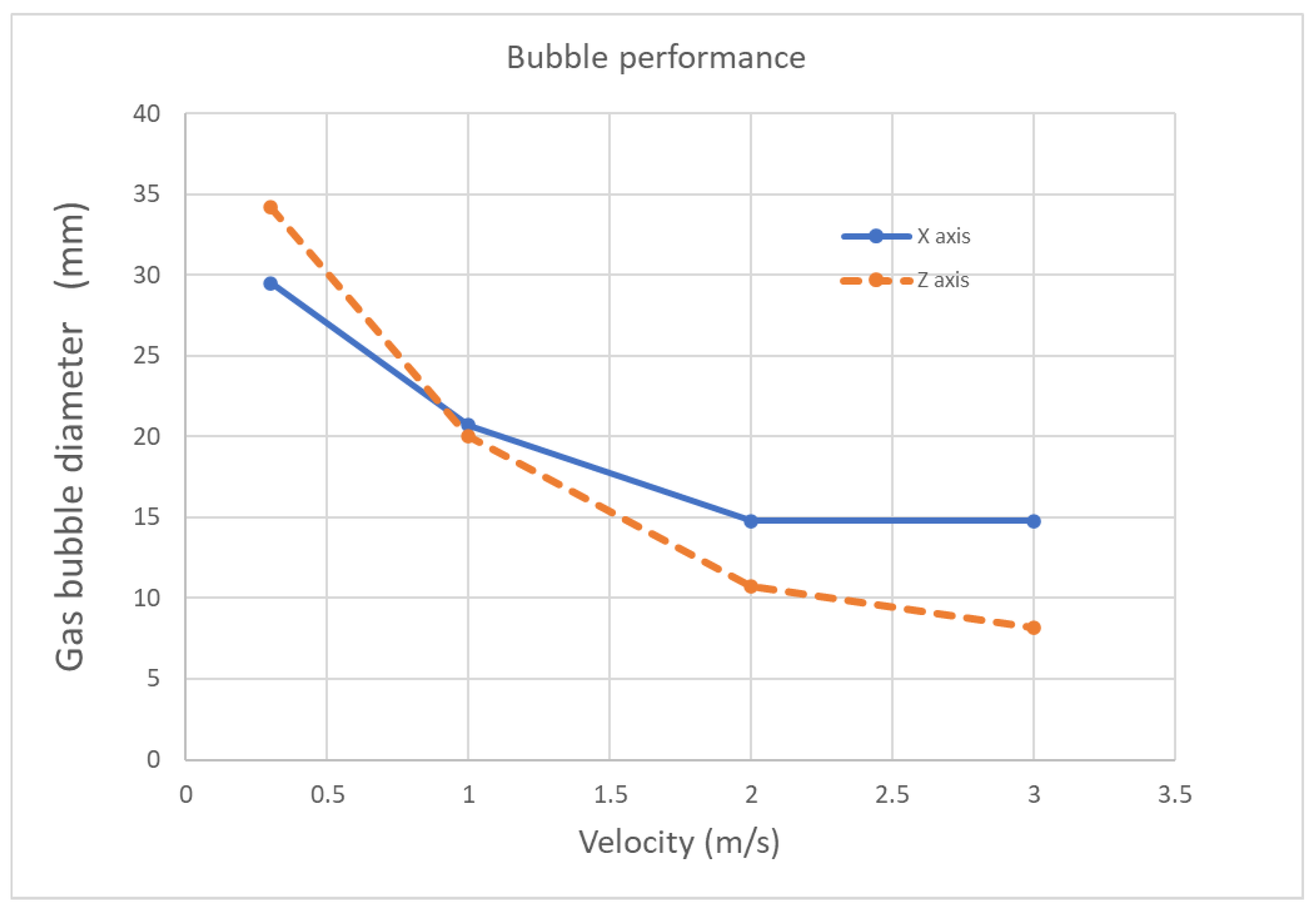
Figure 10, with the axis variation in
Figure 11 for increasing velocities.
It can be noticed that the bubble diameter varies around a mean value of 13 mm. According to the assumption of gas concentration and the requirement of a gas deviation, this fact becomes an important result since t allows defining a standard diameter mm for the deviation pipe to trap the bubble, and it should be located where the bubble remains regular at least at a distance mm for casing the maximum gas before it becomes dispersed.
7. General Remarks
It is important to remark that the main motivation of this work was the requirement of reducing the gas from the mixture in the current operation of the Nuvoil company, to decrease the foaming and emulsion phenomenon in the horizontal separator of a real hydraulic ALS in oil wells, letting the injection pump operate more efficiently. Since the presence of gas represents difficulties in the current operation, the main goal is the gas’s isolation before the mixture enters the horizontal separator.
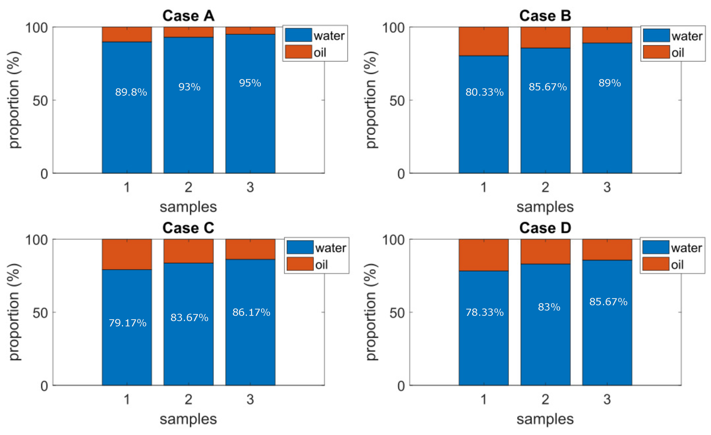
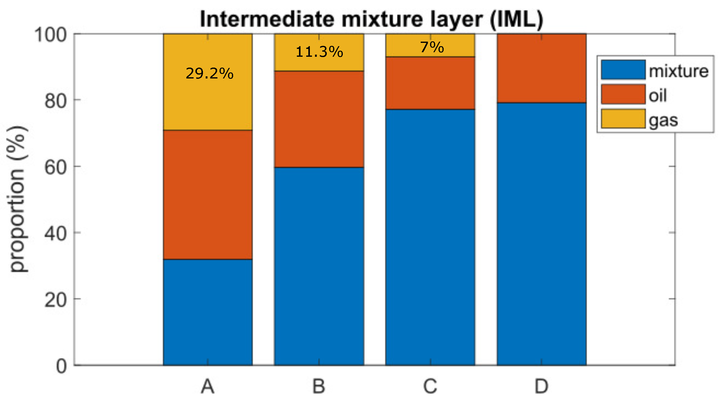
From the results of the presented cases, it can be noticed that the KMS implementation as the inlet device contributes to the gas separation: , , , and of gas for Cases A, B, C, and D, respectively, in an average performance under controlled conditions.
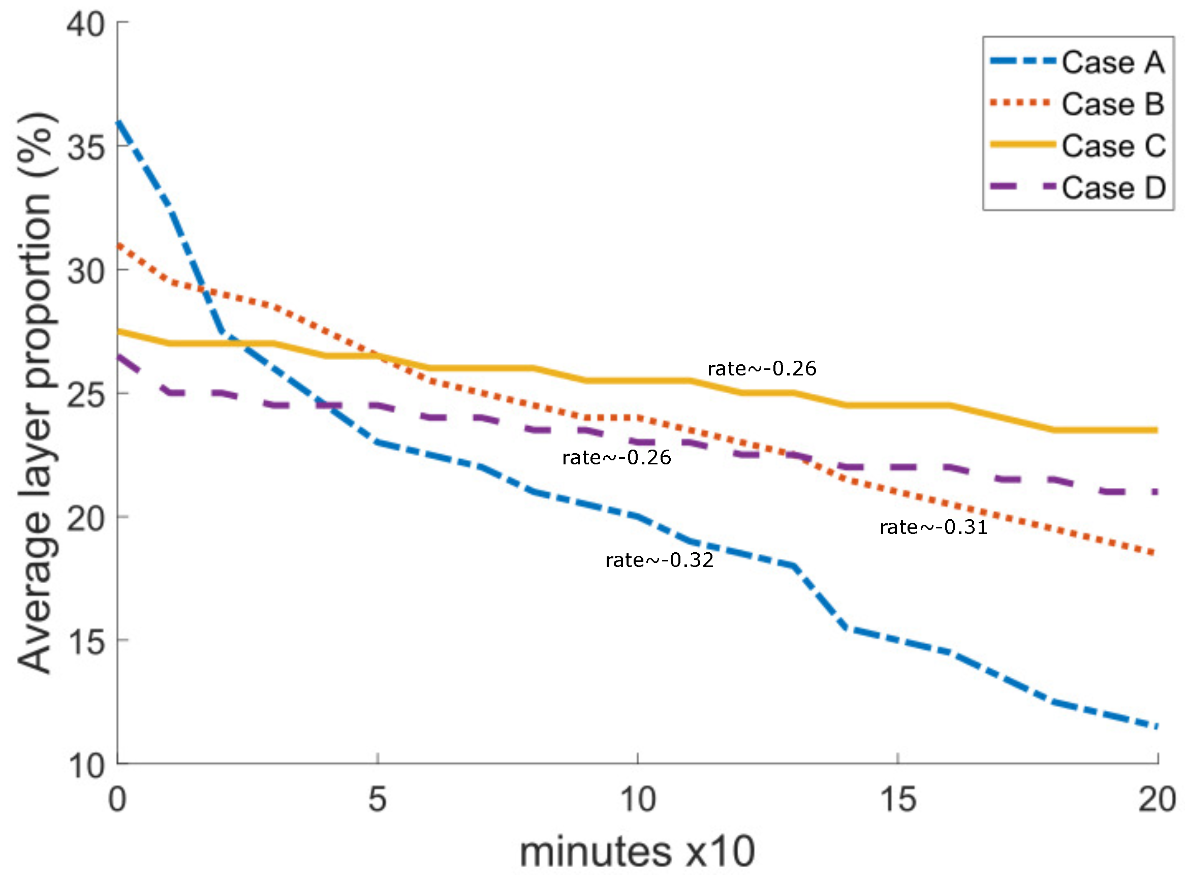
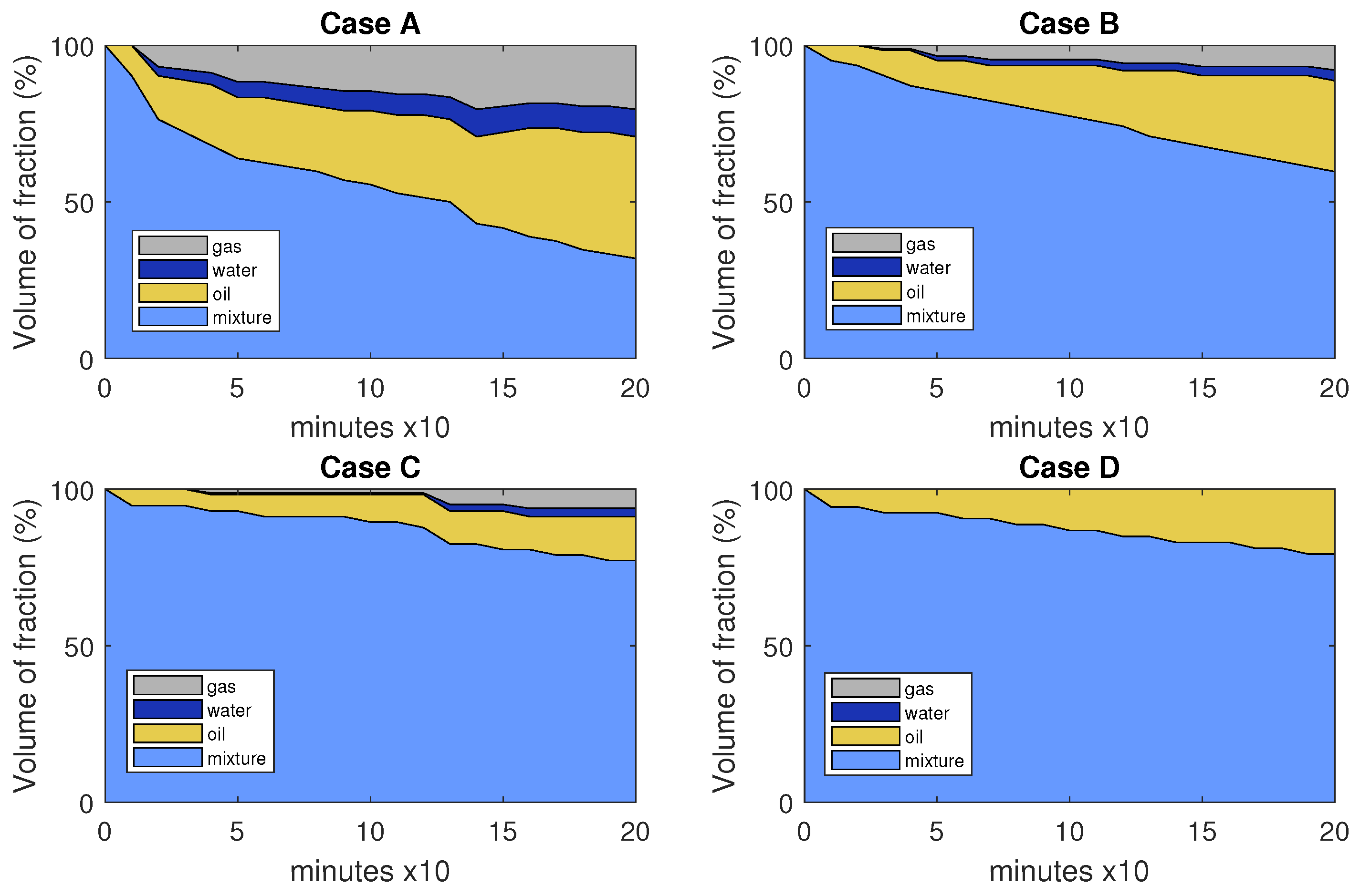
On the one hand, the KMS implementation results in gas reduction from the mixture, which improves the efficiency of the injection pump by enabling it to operate with almost liquid phases. On the other hand, the sedimentation time required to create these liquid phases, which is correlated with higher operation costs, is increased. This is a crucial topic to consider while extracting oil from an oil well since businesses need to determine what will best meet their production targets.
Table 4 summarizes the main criteria to make decisions on the configuration; the current implementation in the real application refers to Case A, but it has the issues already discussed; therefore, Case D may be an alternative following this study regarding the gas reduction.
Recalling
Figure 2 and since the identified bubble and the bottom end of the KMS have a geometry that slightly varies in time because of the rotation, traces of the liquid phase could also be trapped in the physical implementation. Several orifices are distributed in the horizontal section to let liquid fall into the reservoir. In addition, a minimum amount of gas could also fall into the reservoir within the liquid phase and should be separated by sedimentation in the usual way, influencing at the same time the sedimentation times.
Regarding the models of turbulence in
Table 1 for the CFD code, it was shown that
is a fast model to obtain a solution; however, it is not necessarily the most accurate for multiphase flows and transient state simulations. The BLS model, in comparison, produces good results, but the eddies at the end of the KMS are not appreciated as in the SST model, which finally was selected for the experiments.
8. Conclusions
The idea of employing a commercial static mixer arrangement as a separator when the combination has a gas component, as in the case of ALS, was experimentally tested in a prototype platform. It was established that adding the KMS causes the liquids to become more homogeneous and takes longer to separate by sedimentation, but the gas is practically entirely separated.
Since the cyclone effect is still created with the two-element KMS, it is suggested for use in the final implementation. This is further supported by the fact that, in contrast to Cases A and B, where the presence of gas bubbles makes it possible for them to contribute to the separation of water and oil when they rise to the surface, the only method for separating liquids in the absence of gas is the sedimentation by gravity. Since the time required for liquid separation is a drawback to increasing energy efficiency in the equipment at the surface by reducing the gas concentration, it is a crucial problem to consider when using the KMS as an intake device for an ALS. To validate the performance and examine the temporal separation between the liquid components entering the horizontal separator, which is anticipated to change due to the helical phenomena, an actual experimental implementation in oilfields is required in this situation.
The experimental results showed the consistency of the thickness measure over multiple experiments and a suitable model to describe the behavior of the mixture, but a better approximation of the fluid performance after the KMS could be produced because the experimental data were captured by a low-resolution camera. Due to the slow dynamics of sedimentation in the case of lateral monitoring, a slower camera velocity is sufficient to collect the data. Additionally, temperature was treated as constant and ambient in this study; nevertheless, in-depth field tests are needed to confirm the suggested setup.


 ,
, 


