
Determination of Continuous Earthmoving Machinery Course Stability under the Conditions of Cyclic Lateral Loading

 , , and
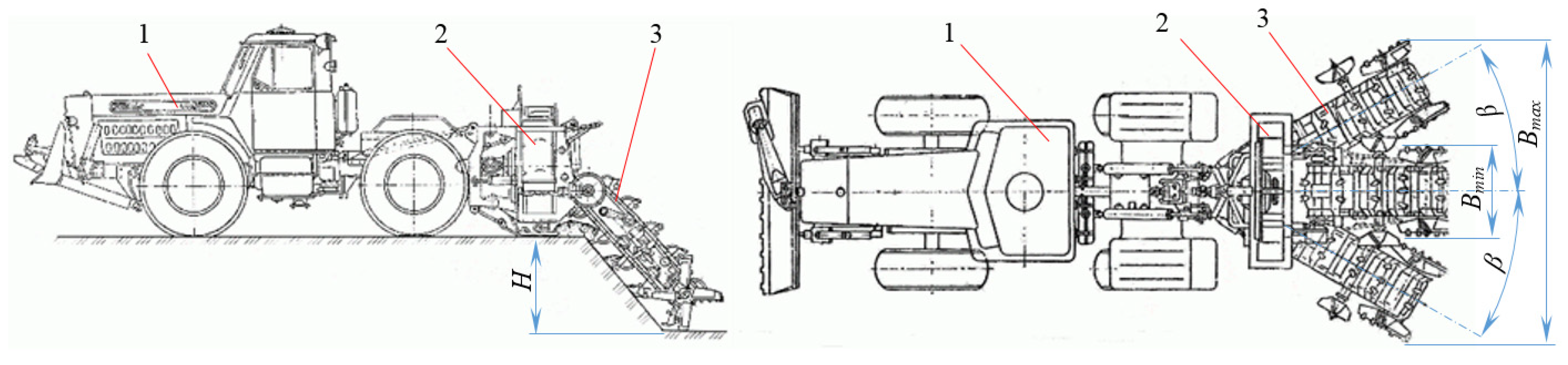
Abstract
:1. Introduction
- To reveal the physical essence of the process of interaction of the UEM rotary actuator with the soil in the process of digging under the condition of the translational and rotational supply of the actuator;
- To develop a mathematical model of the power load of the UEM operating equipment and the machinery in the process of digging the soil under the condition of the two-hinged, two-link hitch of the actuator at the aft of the machine and on its basis the method of the machinery course stability determination as a decisive factor in ensuring its operability.
- Section 1 introduces the subject and provides an overview of the literature;
- Section 2 presents the description of the used methodology, determining the course stability and the experimental setup used;
- Section 3 presents the results of the experimental studies;
- Section 4 summarizes the work;
- Section 5 describes further research.
2. Materials and Methods
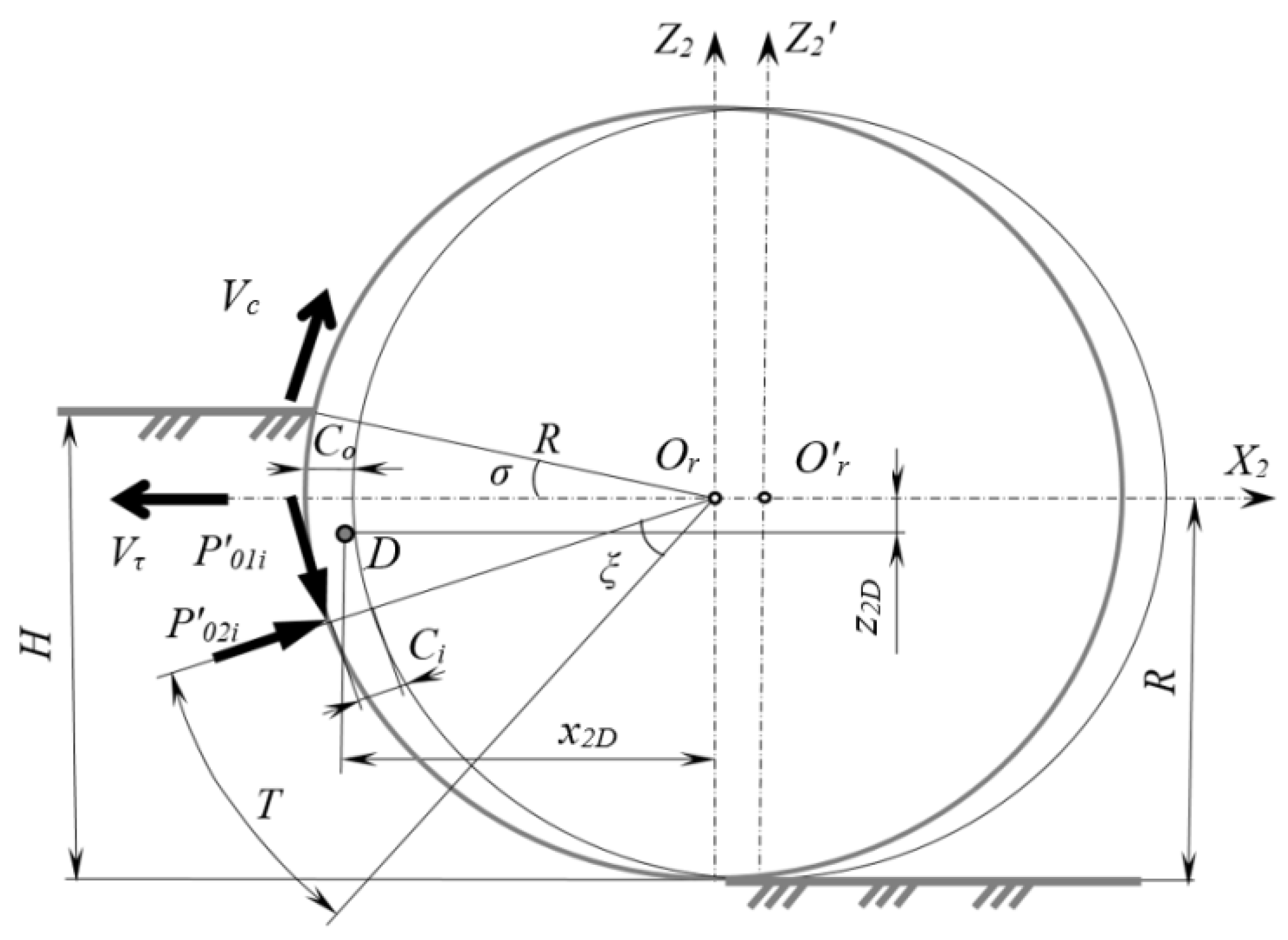
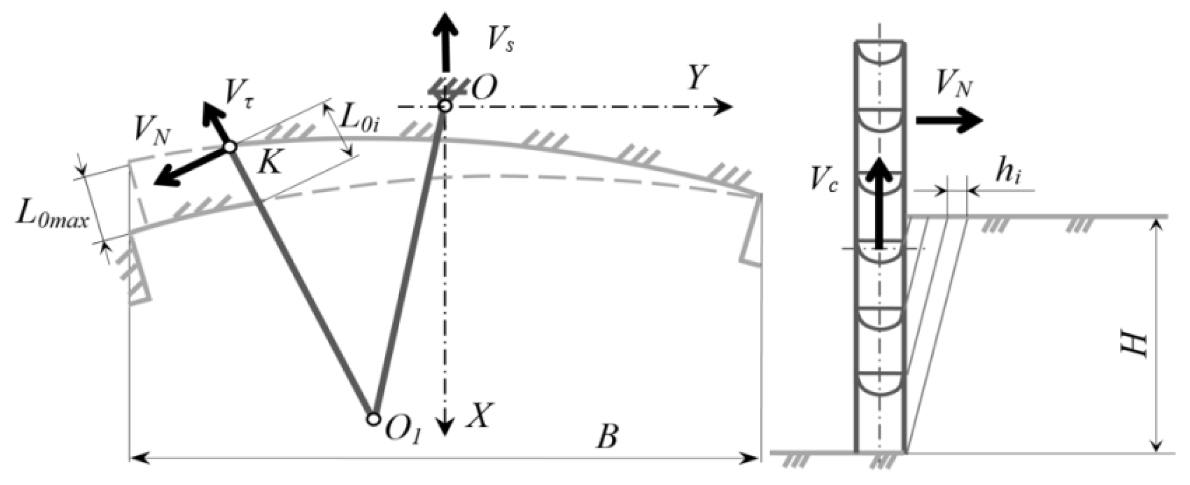
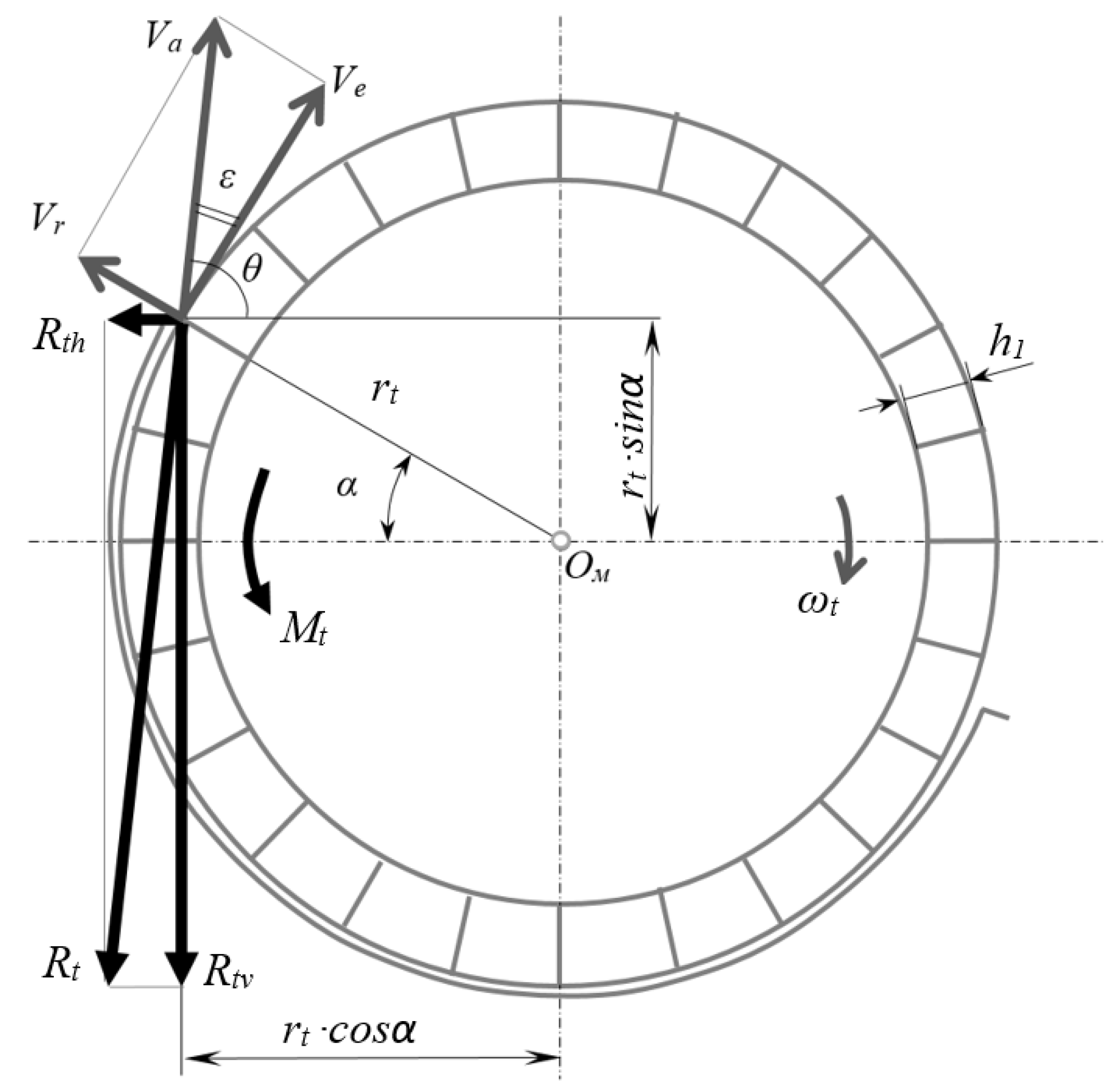
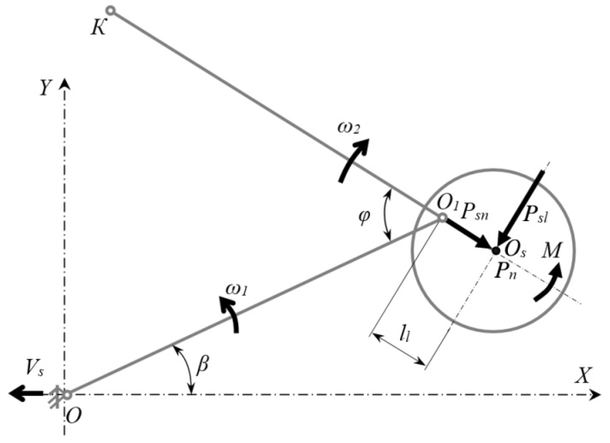
2.1. Determining the Course Stability
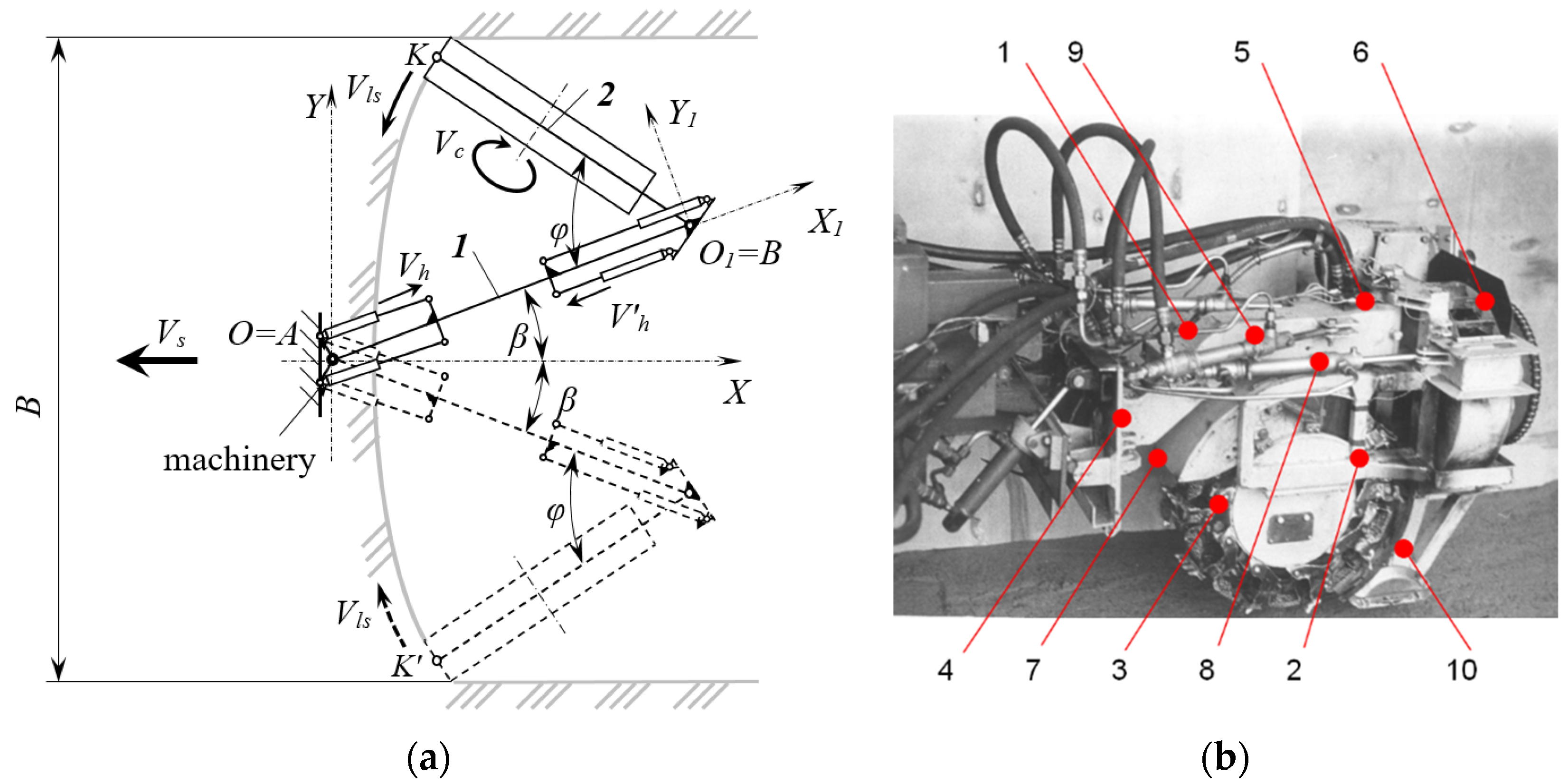
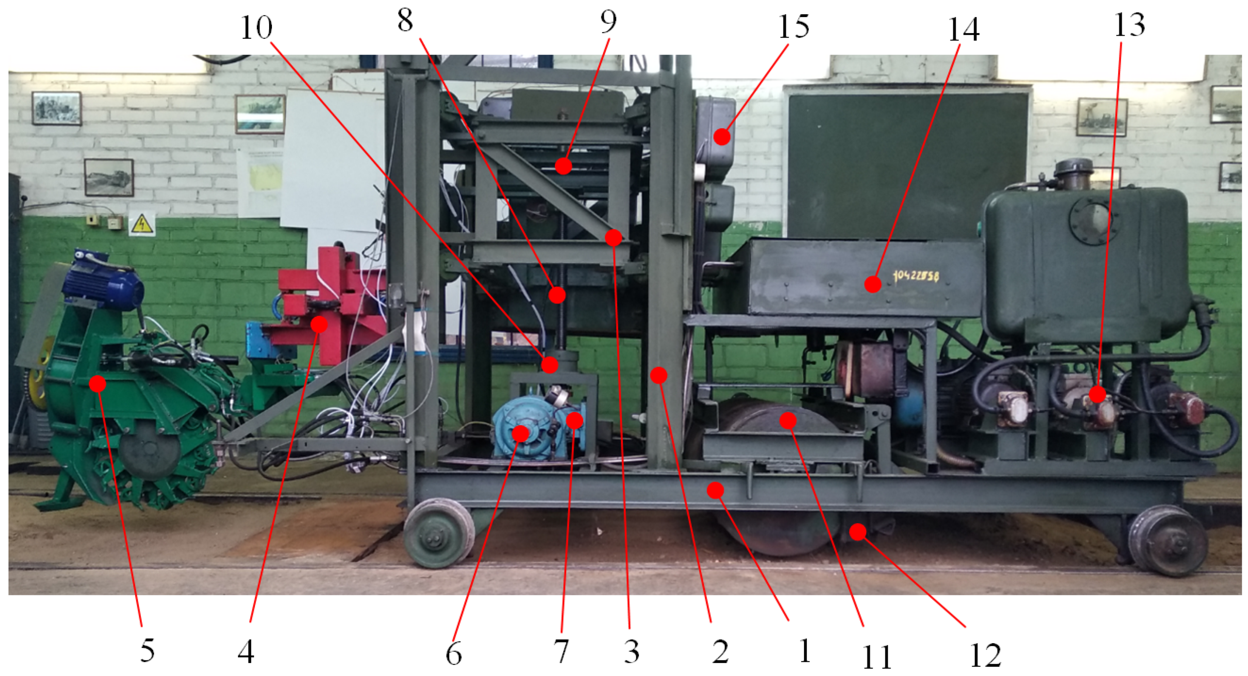
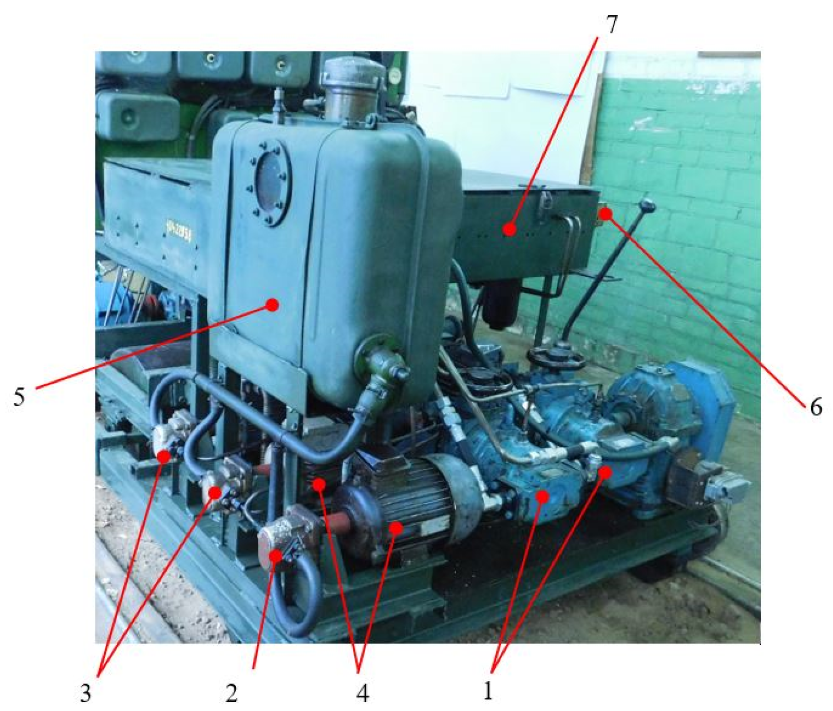
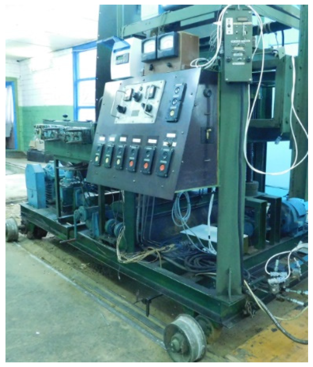
2.2. Experimental Setup
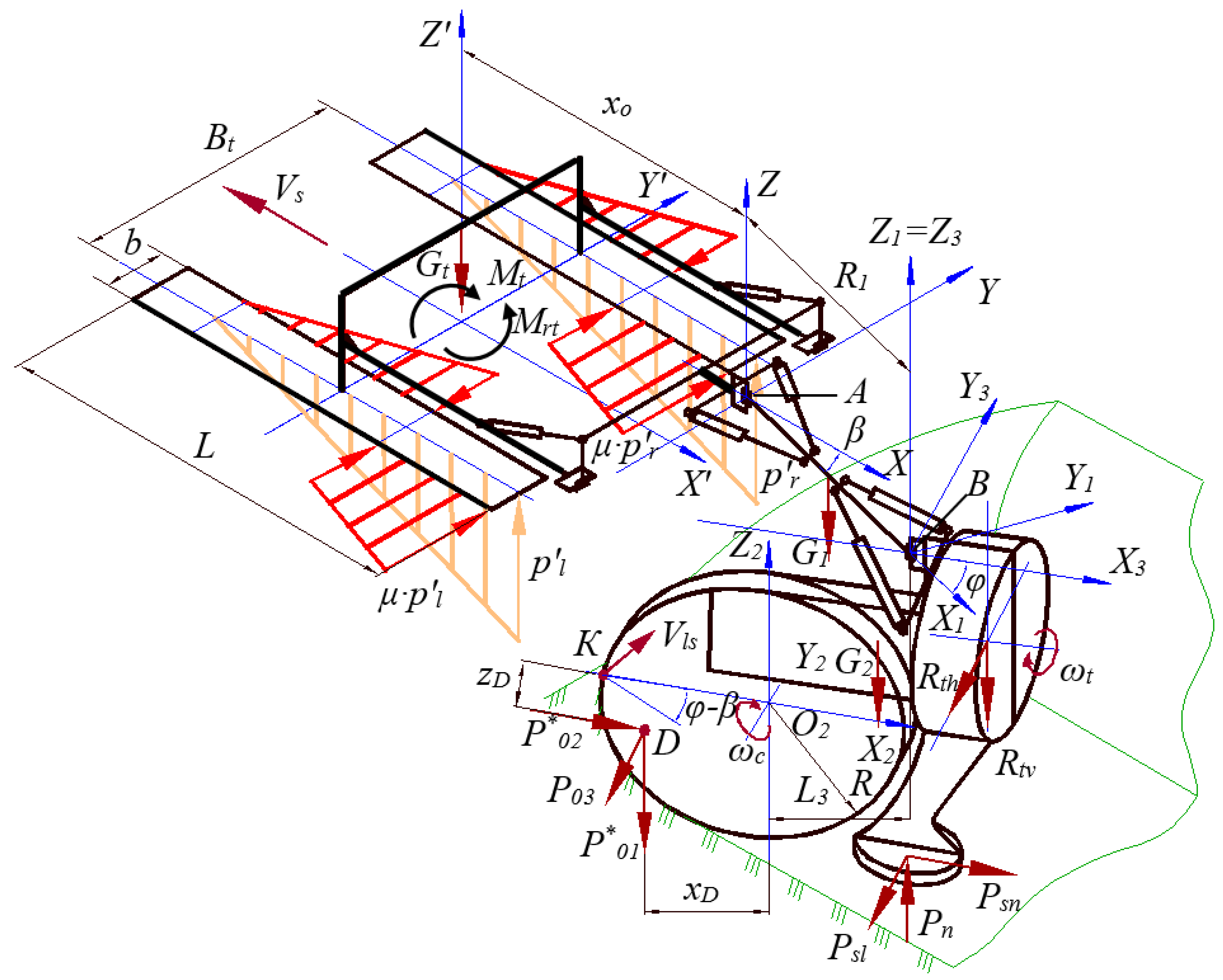
- Traction force and vertical and lateral forces on the actuator rotor when digging the soil;
- Torque on the axis of the rotor when developing the excavation;
- Power on the drive shaft of the thrower;
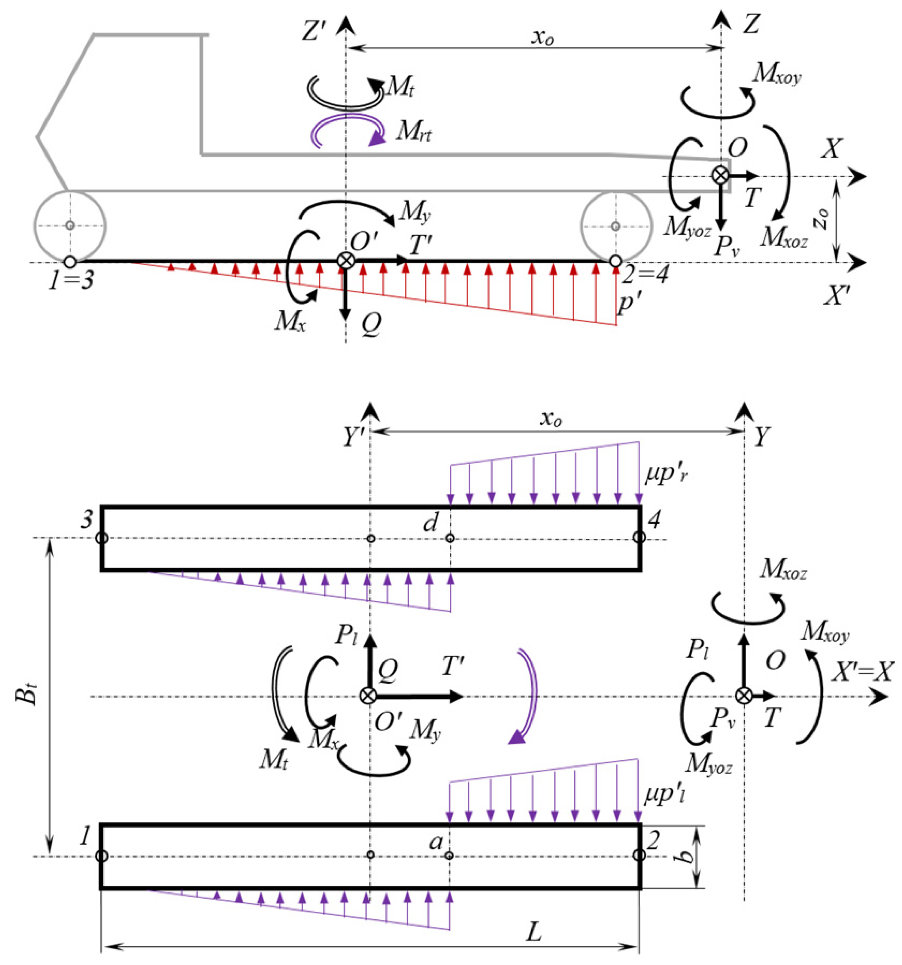
- Total traction forces, vertical and lateral, on the operating equipment reduced to the center of the hinge of the intermediate frame relative to the aft of the machinery;
- Total moments of forces relative to the spatial coordinate system with the center located in the heart of the rotation hinge of the intermediate frame relative to the aft of the machinery.
- The speed of supplying the actuator to the face, Vs;
- The soil cutting speed, Vc;
- The speed of the lateral supply of the actuator to the face, Vls;
- The soil strength according to the hummer, C;
- The width of the excavation (pit) at the level of the day surface of the soil, B;
- The rotor frame rotation delay time (intermediate frame rotation time when the rotor frame rotation mechanism is stopped at the end of each half-cycle), td.
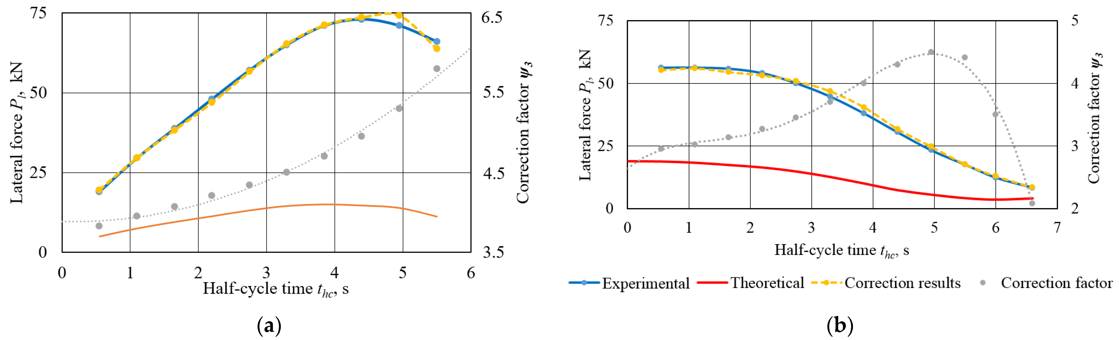
3. Results
4. Conclusions
- The calculation scheme for determining the power load of the UEM with a two-link system of lateral supply of the operating equipment to the face in the mode of digging the soil with maximum productivity has been substantiated and developed for the first time. The dependencies to define the external forces that determine the machinery course stability in the translational and rotational supply mode of the actuator have been obtained.
- The factors whose change determines the value of the loading on the UEM operating equipment in the mode of digging the soil have been determined. These include the width and the depth of the excavation under construction, the speed of the longitudinal motion of the machinery along the face, the speed of the lateral supply to the face of each of the two links of the operating equipment, the soil strength according to the hummer of the Ukrainian State Road Scientific and Research Institute, and the duration of the intermediate frame rotation of the operating equipment at the end of each half-cycle of the operating process.
- The mathematical models of the power loading of the UEM operating equipment and for determining the machinery course have been created in the process of digging the soil. They are based on taking into account the physical features of the digging process in the mode of translational and rotational supply of the rotor actuator to the face. It enables the calculation of the machinery course stability in the operating mode with sufficient accuracy.
- The developed method for determining the stability of the UEM course can be used when creating the industrial samples of trenching earthmoving machinery.
5. Further Research
Author Contributions
Funding
Institutional Review Board Statement
Informed Consent Statement
Data Availability Statement
Conflicts of Interest
References
- Lemu, H.; Kejela, D. Design and modelling of a light duty trencher for local conditions. Adv. Sci. Technol. Res. J. 2018, 12, 303–311. [Google Scholar] [CrossRef]
- Mikhlevskiy, A.I.; Kavalerov, A.A.; Sidorov, K.I.; Lisnovskiy, B.G.; Kvach, A.A.; Suchenko, V.G.; Ivanov, I.I.; Guzenko, N.N.; Redko, D.L.; Shevchenko, G.V.; et al. Trench Digging Machinery (USSR). Copyright certificate № 184732, 21 July 1966. [Google Scholar]
- Musiiko, V.D.; Koval, A.B. Theory and Creation of Innovative Continuous Earthmoving Machinery, 2nd ed.; Lyudmyla: Kiyv, Ukraine, 2018; p. 280. (In Ukrainian) [Google Scholar]
- The Applicant Unit Rig et Equipment Co. Dispositif D’oscillation Transversale Pour Excavatrice-Chargeuse. Patent 2318277, 11 February 1977. [Google Scholar]
- Alvarez Grima, M.; Verhoef, P.N.W. Forecasting Rock Trencher performance using fuzzy Logic11a shorter version of this paper was presented at the 36th US rock mechanics symposium, New York. Int. J. Rock Mech. Min. Sci. 1999, 36, 413–432. [Google Scholar] [CrossRef]
- Vu, M.T.; Jeong, S.-K.; Choi, H.-S.; Oh, J.-Y.; Ji, D.-H. Study on down-cutting ladder trencher of an underwater construction robot for Seabed Application. Appl. Ocean Res. 2018, 71, 90–104. [Google Scholar] [CrossRef]
- Vu, M.T.; Choi, H.-S.; Kim, J.-Y.; Tran, N.H. A study on an underwater tracked vehicle with a ladder trencher. Ocean Eng. 2016, 127, 90–102. [Google Scholar] [CrossRef]
- Hu, K.; Cheng, K. Dynamic modelling and stability analysis of the articulated tracked vehicle considering transient track-terrain interaction. J. Mech. Sci. Technol. 2021, 35, 1343–1356. [Google Scholar] [CrossRef]
- Benoit, O.; Gotteland, P.; Quibel, A. Prediction of trafficability for tracked vehicle on broken soil: Real size tests. J. Terramechanics 2003, 40, 135–160. [Google Scholar] [CrossRef]
- Rahman, A.; Mohiuddin, A.K.; Hossain, A. Performance measurements of a tracked vehicle system. Int. J. Automot. Technol. 2011, 12, 503–512. [Google Scholar] [CrossRef]
- He, R.; Sandu, C.; Khan, A.K.; Guthrie, A.G.; Schalk Els, P.; Hamersma, H.A. Review of terramechanics models and their applicability to real-time applications. J. Terramechanics 2019, 81, 3–22. [Google Scholar] [CrossRef] [Green Version]
- Kim, S.-H.; Lee, Y.-S.; Sun, D.-I.; Lee, S.-K.; Yu, B.-H.; Jang, S.-H.; Kim, W.; Han, C.-S. Development of bulldozer sensor system for estimating the position of Blade Cutting Edge. Autom. Constr. 2019, 106, 102890. [Google Scholar] [CrossRef]
- Bandurov, V.M.; Baranov, I.M.; Goryachev, V.F.; Zhabin, V.F.; Kakusha, N.I.; Kavalerov, A.A.; Kochev, N.I.; Lobanov, N.V.; Maksimov, V.A.; Medovnikov, V.P.; et al. Rotor Actuator of Universal Earthmoving Machinery (USSR). Copyright certificate № 905387, 15 February 1982. [Google Scholar]
- Farmer, I.W. Performance of chain trenchers in mixed ground. J. Constr. Eng. Manag. 1996, 122, 115–118. [Google Scholar] [CrossRef]
- Koval, A.B. Determining the Conditions for Ensuring the Course Stability of Universal Earthmoving Machinery. Ph.D. Thesis, National Transport University, Kyiv, Ukraine, 2014; 218p. (In Ukrainian). [Google Scholar]
- Koval, A.B. Physical features of loading formation on the actuators of universal earthmoving machinery. In Col. of Scient. Papers Construction. Materials Science. Mechanical Engineering. Intensification of the Operating Processes of Construction and Road Machinery; Koval, A.B., Ed.; Series: Lifting-and-Transport, Construction and Road Machinery and Equipment; SHEI “PSACEA”: Dnepropetrovsk, Ukraine, 2014; Volume 79, pp. 125–132. (In Ukrainian) [Google Scholar]
- Dombrovskiy, N.G.; Mayevskiy, A.G.; Gomozov, I.M.; Gilis, V.M. Theory and Calculation of the Caterpillar Mover of Earthmoving Machinery; Technics: Kyiv, Ukraine, 1970; 192p. (In Russian) [Google Scholar]
- Guskov, V.V.; Opeiko, A.F. Theory of Rotation of Caterpillar Machinery; Mechanical Engineering: Moscow, Russia, 1984; 168p. (In Russian) [Google Scholar]
- Sitorus, P.E.; Ko, J.H.; Kwon, O.S. Parameter study of chain trenching machines of underwater construction robots via analytical model. In Proceedings of the OCEANS 2016 MTS/IEEE Monterey, Monterey, CA, USA, 19–23 September 2016. [Google Scholar] [CrossRef]
- Kim, J.; Kwon, O.S.; Hai, N.L.; Ko, J.H. Study on the design of an underwater chain trencher via a genetic algorithm. J. Mar. Sci. Eng. 2019, 7, 429. [Google Scholar] [CrossRef] [Green Version]
- Zelenin, A.N. Basics of Soil Destruction by Mechanical Means; Mechanical Engineering: Moscow, Russia, 1968; 375p. (In Russian) [Google Scholar]
- Garbuzov, Z.Y.; Ilgisonis, V.K.; Mutushev, G.A.; Naret, G.B.; Podborskiy, L.E.; Uspenskiy, V.P. Continuous digging machinery. In Constructions and Calculations; Ye, L., Podborskiy, M., Eds.; Mechanical Engineering: Moscow, Russia, 1965; 275p. (In Russian) [Google Scholar]
- Dmytrychenko, M.F.; Bilyakovych, M.O.; Musiiko, V.D.; Koval, A.B.; Voshchak, Y.V.; Kucher, O.P.; Horkovenko, O.V. Universal Strain Gauge and Method for Determining Force Parameters of Spatial Loadings of Earthmoving Machinery Actuators. Patent № 111690, 25 May 2016. (In Ukrainian). [Google Scholar]


Publisher’s Note: MDPI stays neutral with regard to jurisdictional claims in published maps and institutional affiliations. |
© 2022 by the authors. Licensee MDPI, Basel, Switzerland. This article is an open access article distributed under the terms and conditions of the Creative Commons Attribution (CC BY) license (https://creativecommons.org/licenses/by/4.0/).
Share and Cite
Smieszek, M.; Musiiko, V.; Mateichyk, V.; Tsiuman, M.; Koval, A.; Mościszewski, J. Determination of Continuous Earthmoving Machinery Course Stability under the Conditions of Cyclic Lateral Loading. Appl. Sci. 2022, 12, 7029. https://doi.org/10.3390/app12147029
Smieszek M, Musiiko V, Mateichyk V, Tsiuman M, Koval A, Mościszewski J. Determination of Continuous Earthmoving Machinery Course Stability under the Conditions of Cyclic Lateral Loading. Applied Sciences. 2022; 12(14):7029. https://doi.org/10.3390/app12147029
Chicago/Turabian StyleSmieszek, Miroslaw, Volodymyr Musiiko, Vasyl Mateichyk, Mykola Tsiuman, Andrii Koval, and Jakub Mościszewski. 2022. "Determination of Continuous Earthmoving Machinery Course Stability under the Conditions of Cyclic Lateral Loading" Applied Sciences 12, no. 14: 7029. https://doi.org/10.3390/app12147029