1. Introduction
The understandable desire for increasingly efficient machines and components is pushing the materials used to date to their limits. To extend these limits further, new alloy systems are constantly being investigated for their properties and technical applicability. In recent years, a new group of alloys has increasingly become the focus of investigations, the complex concentrated alloys (CCAs). These alloys can exhibit outstanding properties compared to conventionally used alloy systems (e.g., high ductility combined with high strength and storage of liquefied gases) [
1]. A better-known part of the complex concentrated alloys are the high entropy alloys. CCAs are multi-principal alloy systems typically consisting of at least four different elements with a near equiatomic composition (between 5 wt.-% and 35 wt.-%).
Shortly after their detailed description by Yeh et al. [
2] and Cantor et al. [
3] in the early 2000s, the interest of emerging additive manufacturing technologies for these alloy systems also started. In 2018, the state of research achieved so far was summarized by Chen et al. [
4], others in 2017 [
5], and in 2020 [
6]. The work done so far shows the possible outstanding properties of this alloy group. Unfortunately, the number of possible combinations and variations in chemical composition for this alloy group is almost infinite, so the work on characterization of the possible properties is just beginning. This is especially true if the process variables during production and any subsequent heat treatments are also taken into account.
Due to recent developments in the field of additive manufacturing, the combination of novel alloy concepts, such as complex concentrated alloys and additive manufacturing processes, is also becoming the focus of research. For example, studies have already been carried out on the use of CCAs for various powder-based additive manufacturing processes [
7,
8,
9] and high throughput processes as well [
10]. Besides the powder processes, CCAs are getting in the focus of other additive manufacturing, such as wire and arc additive manufacturing processes as well.
1.1. Wire and Arc Additive Manufacturing
Wire and arc additive manufacturing (WAAM) is a fast emerging additive manufacturing technique and is utilized for a wide range of materials [
11,
12,
13,
14]. The main material focus in research is currently steel, aluminum, and titanium. Wire and arc additive manufacturing is part of the direct energy deposition (DED) processes and summarizes the different welding processes, such as TIG- and GMA-welding. In this work, the focus lies on the GMA-welding-based additive manufacturing. This process allows a large variety in geometries to be manufactured, including overhangs [
15,
16]. Furthermore, it can be used for a wide range of materials and also multi-material and functionally graded approaches [
17,
18,
19,
20,
21,
22,
23,
24,
25]. In this case, the manufacturing process could have a significant impact on the properties of the materials that are summarized and shown in [
13,
26,
27] and need to be considered for the prediction of the material properties. The WAAM-process needs in every case a substrate material for the start of the manufacturing process. These materials are not always of the same chemical composition of the additively manufactured part. Such mixed material joints are commonly known in welding and possible to achieve, e.g., in explosion welding [
28,
29] or for cladding [
14].
One limiting factor is the lack of knowledge about the welding or additive manufacturing and the influence of these processes on the properties of the CCAs [
30]. Another limiting factor of this additive manufacturing process is the availability of the used wire-shaped filler materials. Classically, these are manufactured as solid wires. For these solid wires, special melts are prepared and the feedstock is cast for subsequent forging and wire drawing processes. This limits the range of possible alloy systems, especially if they have unknown processing properties. In addition to solid wires, cored wires have also become well established. These have a formed sheet metal strip outer sheath filled with powder. This allows a wider range of possible alloy compositions with relatively small quantities of filler. As a relatively new variant of additives, cable-like wound filler wires have become established in research. Here, too, the degrees of freedom in composition are significantly greater for small quantities of filler compared to solid wires. These cable-like fillers have been realized for complex concentrated alloys; demonstrated in [
31,
32,
33]. Here, the limiting factor is the available diameter of the different alloying elements.
Overall, currently, the metal-cored fillers offer the widest range in possible composition, and they will be the focus in this work.
1.2. Aim of This Work
The presented work is intended to clarify whether the selected alloy system can be produced by using a metal-cored wire and which process boundary conditions make this possible. In particular, alloying elements burn-off and the usage of different shielding gases will be presented. An initial characterization of the properties of the additively manufactured CCA regarding the mechanical–technological properties together with a first comparison of the wear resistance completes the work. The used composition is based on the compositions given in [
34] and has been adjusted to allow the manufacturing of the metal-cored wire with a diameter of 2.4 mm.
2. Materials and Methods
In the following sections, the used materials, welding equipment, and analytical methods will be briefly described.
2.1. Material
A metal-cored filler wire with a diameter of 2.4 mm was used as the filler material for the additive manufacturing of the test piece. The nominal chemical composition of the baser material and the cored wire is shown in
Table 1.
It consists of a shell made of FeNi36. With the filling, the missing element contents are realized. A mixture of pre-alloyed powders and pure powders has been used.
The substrate on which a wall-like structure has been manufactured was a plate of S355 steel with the dimensions of 355 mm × 350 mm × 15 mm. The surface of the substrate has been sand-blasted before the initial welding tests.
2.2. Welding—Strategy and Sequence
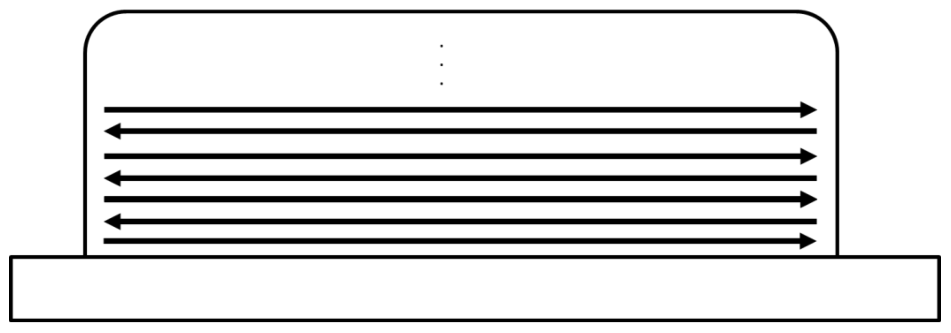
The welding direction was chosen in an alternating manner to compensate for thermally induced geometric errors on both sides of the resulting wall structure,
Figure 1. A similar approach has already been shown in [
35,
36] and others.
The welding parameters used to produce the wall structure are summarized in
Table 2. The use of a 2.4 mm thick metal-cored wire made it necessary to use the non-synergy mode of the welding power source. A mixture of 85% Argon and 15% Helium was used as shielding gas. In preliminary tests, a mixture of 82% argon and 18% CO
2 as well as unmixed argon were used. In the case of the mixed gas with CO
2, pore formation was observed. When pure argon was used, the melt showed signs of melt run-off and resulting bonding defects. The welding current was around 205 A, and the welding voltage was set to 16.6 V. The welding speed was set to 50 cm/min and the wire feed was 3.5 m/min. The welding process parameters were determined in preliminary tests in such a way that a stable arc was achieved over the entire build-up height and, in addition, an equal build-up height between the layers could be realized. Furthermore, care was taken to ensure that the energy input (primarily determined by welding current/wire feed) was located in the lower spectrum, as is more typical for arc-based additive manufacturing.
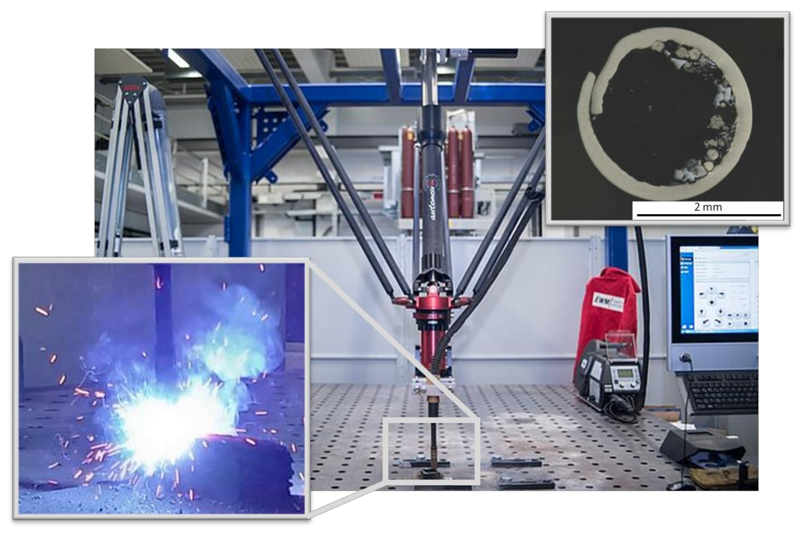
Figure 2 shows the wall-like structure during the additive manufacturing process and the used additive manufacturing robot based on a tripod robot system. In addition, the
Figure 2 shows the cross section of the used metal-cored filler. Some welding spatter occurring is visible. The welding power source was a EWM Titan XQ Puls. The welding mode was set to non-synergetic. An interlayer temperature of less than 200 °C was kept between all layers.
2.3. Analytical Methods
In the following section the analytical methods are briefly described.
2.3.1. Microstructural and Chemical Analysis
For the microstructure analysis, 3 samples were taken transverse to the welding direction and embedded in a polymer. These were then ground and prepared for reflected light microscopy by polishing. For visualization of the microstructure, an etching with V2A mordant has been conducted. The composition of the etchant is:
- -
100 cm3 Hydrochloric acid—HCl
- -
100 cm3 water—H2O
- -
10 cm3 nitric acid—HNO3
- -
1 cm3 mordant according to Dr. Vogels
Afterwards pictures of the microstructure were taken using optical light microscopy and scanning electron microscopy. The chemical composition has been determined using energy dispersive X-ray spectroscopy (EDX) and X-ray fluorescence analysis (XFA).
To determine the crystal structure, X-ray diffractometer investigations were carried out with the aid of an X-ray diffractometer from Panalytical (Empyrean) Cu X-ray tube operated at 40 kV and 40 mA and a PIXcel 1D detector (255 channels, 14 mm active length). Data were collected between 20 and 120 °2θ with a stepsize of 0.026 °2θ and a time of 20 s per step.
2.3.2. Mechanical Properties and Hardness
The determination of the mechanical parameters was carried out according to DIN ISO 6892 [
37]. The hardness of the component was determined according to DIN ISO 6507 [
38]. The hardness measurements were performed on the obtained cross-sections. The tensile specimen had the form E (b
0 = 6, L
t = 104) in accordance with DIN 50125 [
39].
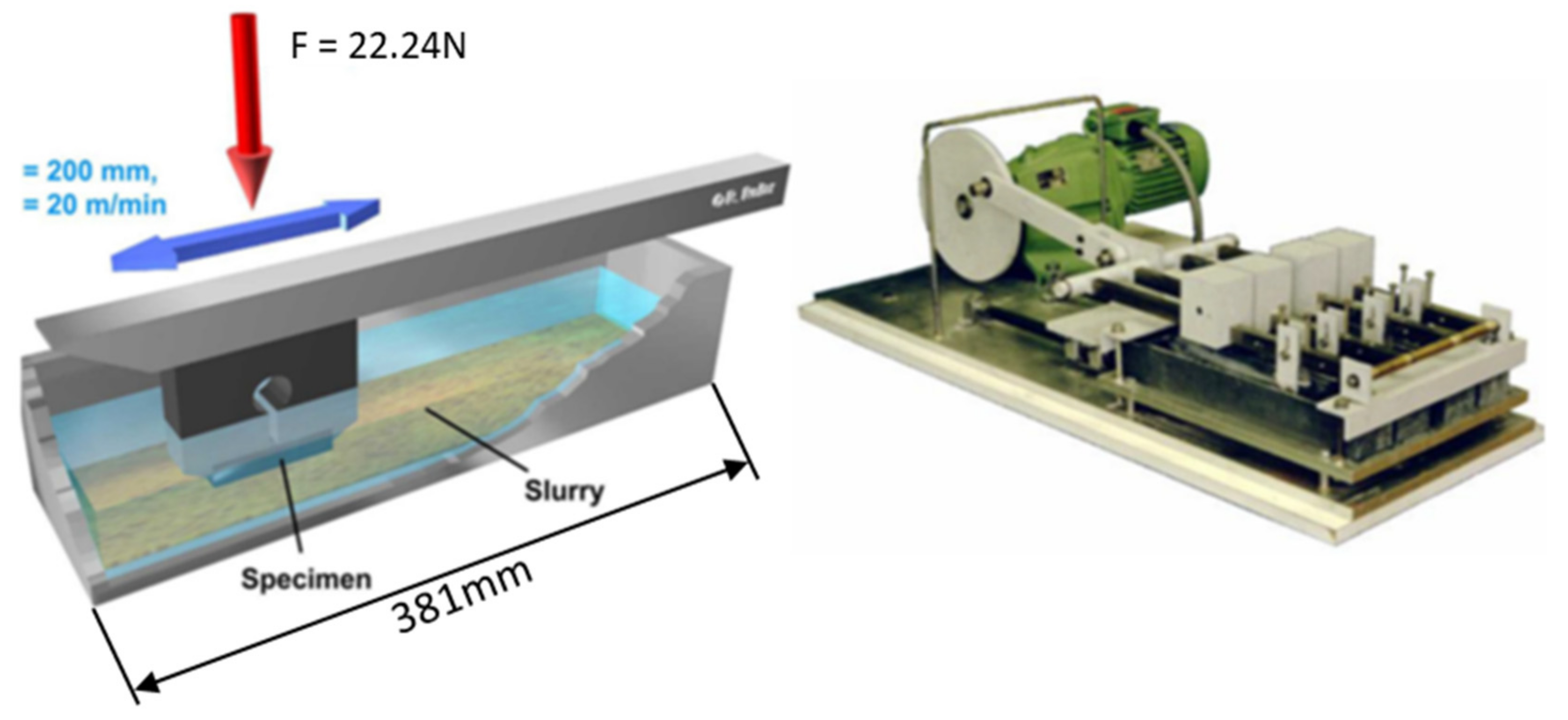
2.3.3. Miller Test
To determine the behavior of materials under three-body abrasive wear, the Miller test according to ASTM G75 can be used [
40]. The test has been carried out in accordance with the standard. A sample was moved cyclic under a defined load of 22.24 N in an abrasive suspension against chloroprene rubber at a speed of 20 m/min,
Figure 3. This test has also been used in [
34,
41].
2.3.4. Density
The density of the alloy was determined with a pycnometer using distilled water and the specimen designated for wear testing.
2.3.5. Thermal Expansion Coefficient
The thermal expansion coefficient has been measured using a push rod dilatometer. The push rod dilatometer used consists of a furnace, the sample holder, and the unit for recording and evaluating the measured values. The sample is located in a tube made of ceramic. It is firmly connected to a rod that transmits the change in length of the specimen for measurement value acquisition. The thermal expansion coefficient is then calculated using the measured values.
2.3.6. Specimen Orientation and Positioning
Figure 4 shows the orientation and location of the specimens in the manufactured wall-like structure. The specimen was cut out using wire-based electric discharge machining (EDM) followed by grinding to remove the EDM-surface.
3. Results
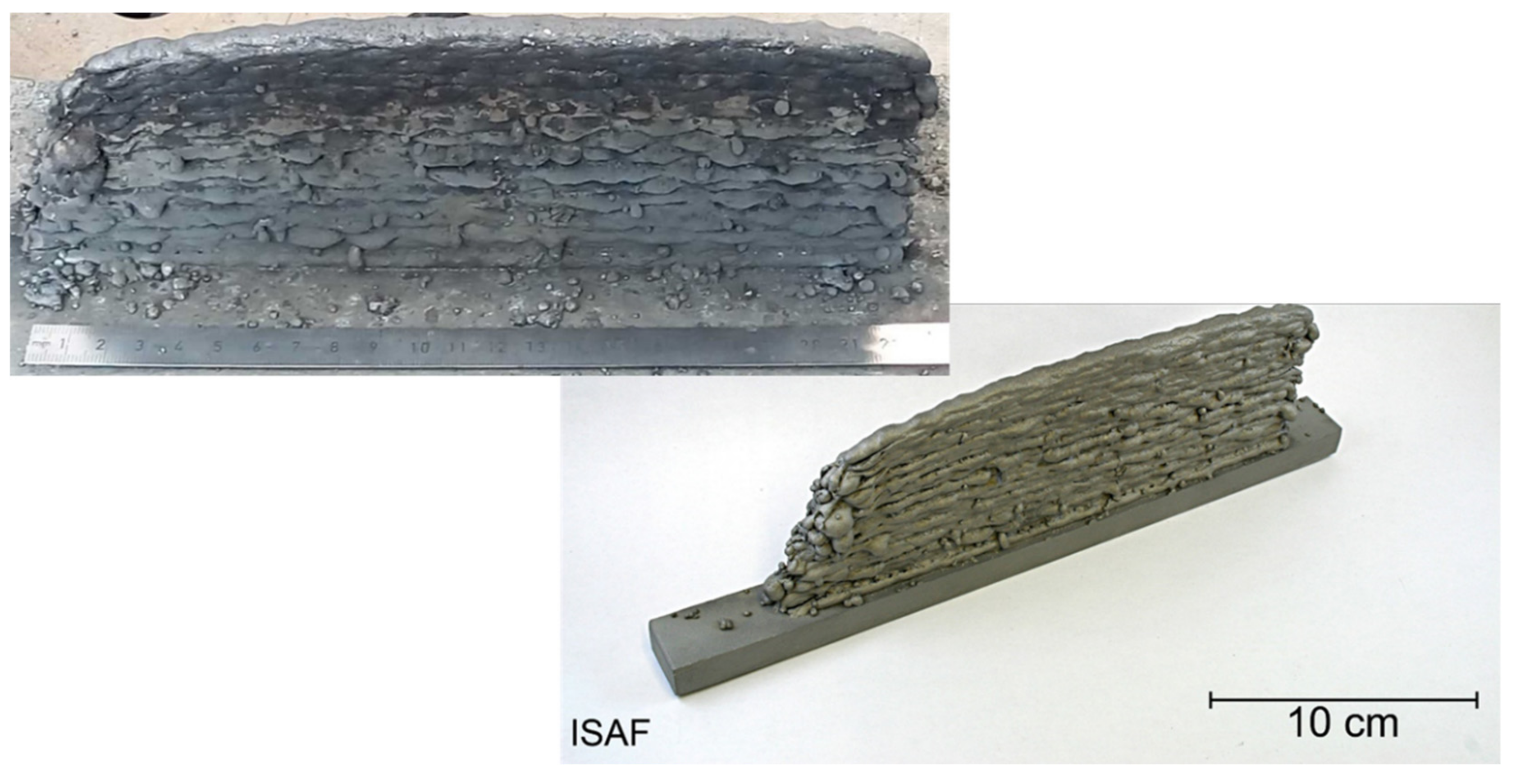
Figure 5 shows the wall-like structure after deposition and after sandblasting.
The surface of the wall-like structure is very non-uniform. This is due on the one hand to the wire diameter used—the surface quality of WAAM-produced components usually increases with a small wire diameter—and on the other hand to a hitherto rudimentary adjustment of the process variables. In addition, on the one side of the structure there is an increasing geometrical defect (left). This is due to a further increase in ignition problems in the welding process.
3.1. Chemical Compsition and Burn Off
To be able to compare the nominal alloy composition with the composition present in the component, the chemical composition was determined by means of X-ray fluorescence analysis (XFA). The comparison between the two compositions is given in
Table 3.
Overall, the chemical composition is found to be comparable to the nominal composition. A clear burn-off of alloying elements is not discernible. The slight burn-off of chromium, molybdenum, and cobalt was to be expected, especially for molybdenum and chromium since the burn-off of these alloying elements is known for other materials.
3.2. Mechanical Properties
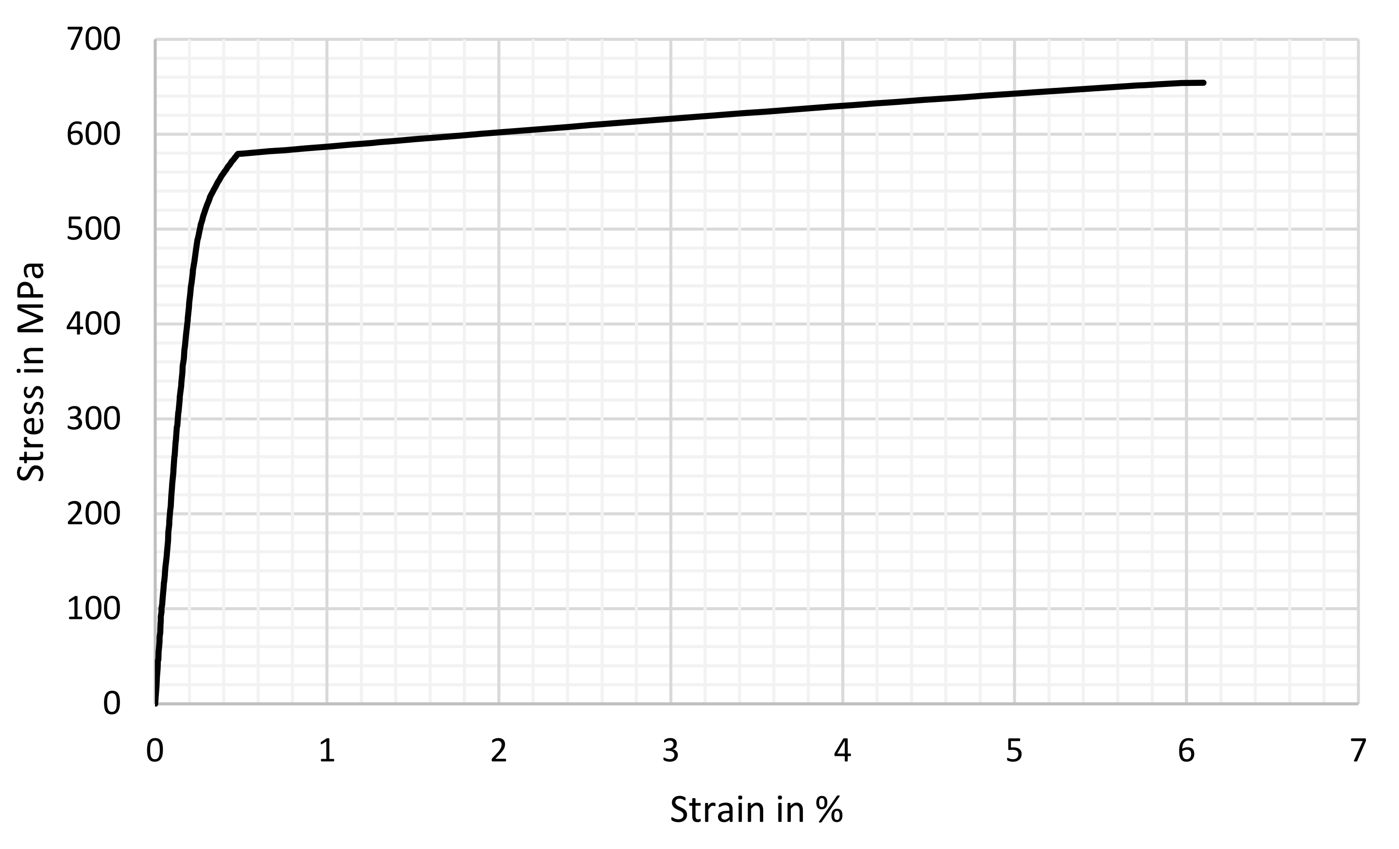
Table 4 shows the mechanical properties determined in the tensile test parallel to the welding direction and represents the mean value of three samples. A stress–strain curve is shown as an example in
Figure 6.
The additively manufactured complex concentrated alloy investigated has a Young’s modulus of approx. 246 GPa, a yield strength of approx. 530 MPa, and a tensile strength of approx. 560 MPa. The elongation at break determined over the three tests carried out was 2.1%. One specimen showed a very brittle material behavior without plastic deformation. This is attributed to imperfections due to manufacturing.
3.3. Hardness
The mean value of the hardness from 10 measurements distributed over the cross-section of the sample was 257HV10. The range of the measured hardness values was between 252HV10 and 270HV10.
3.4. Microstructure
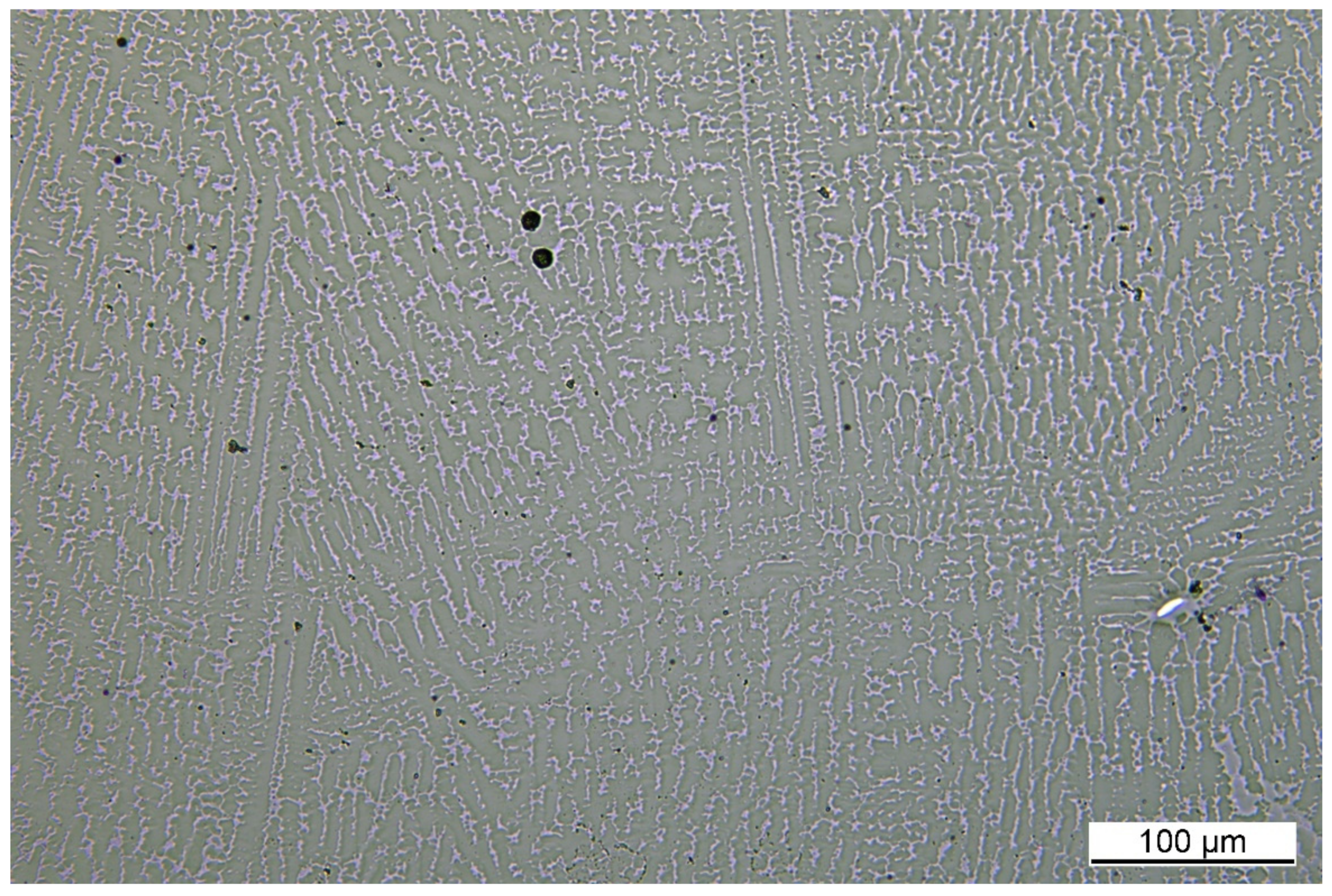
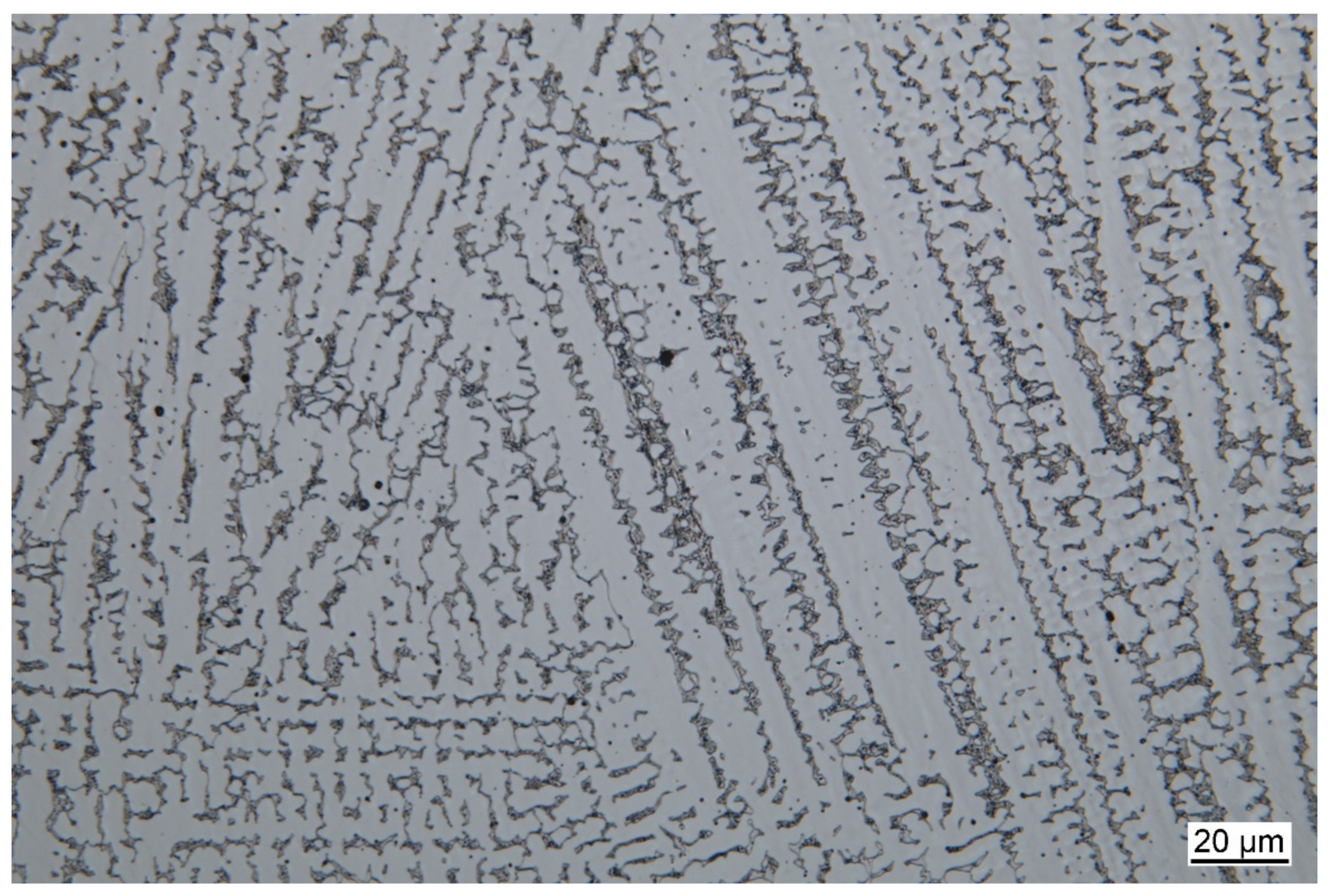
Figure 7 and
Figure 8 show the microstructure of the additively manufactured wall-like structure in 200× magnification in the unetched state and in 500× magnification in the etched state. The etching was carried out with V2A mordant as described in the methods.
A dendritic solidification structure is clearly visible in both images. Inter-dendritic residual solidification is also visible. The internal structure of this residual solidification, as shown in
Figure 8, indicates a eutectic mixture. However, proof of this eutectic is still pending and will follow in further studies. Furthermore,
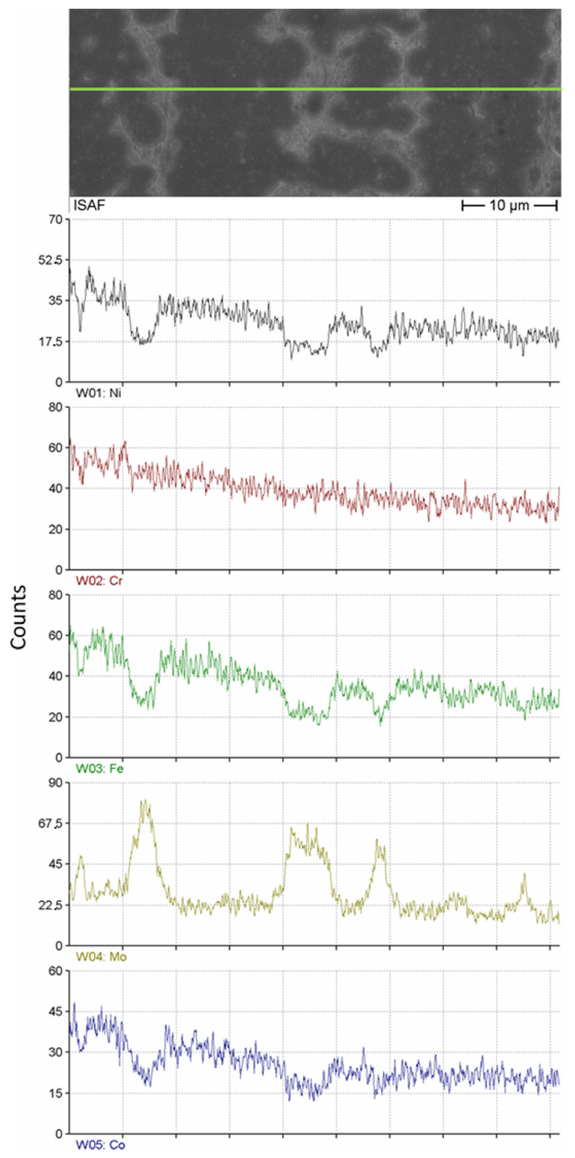
Figure 9 shows that the chemical composition between the two phases clearly differs in the content of nickel, chromium, iron, molybdenum, and cobalt, so that it can now be assumed that it is a two-phase complex concentrated alloy due to additive manufacturing.
Figure 9 shows an SEM image of the microstructure. The green line represents the position for a line EDX scan. The corresponding counts of the analyzed elements are shown below.
A Mo-rich phase is shown, in which the other main alloying elements are contained in lower amounts than in the second phase, which is rather Mo-poor. A detailed determination of the phases, their structure, and composition is still pending.
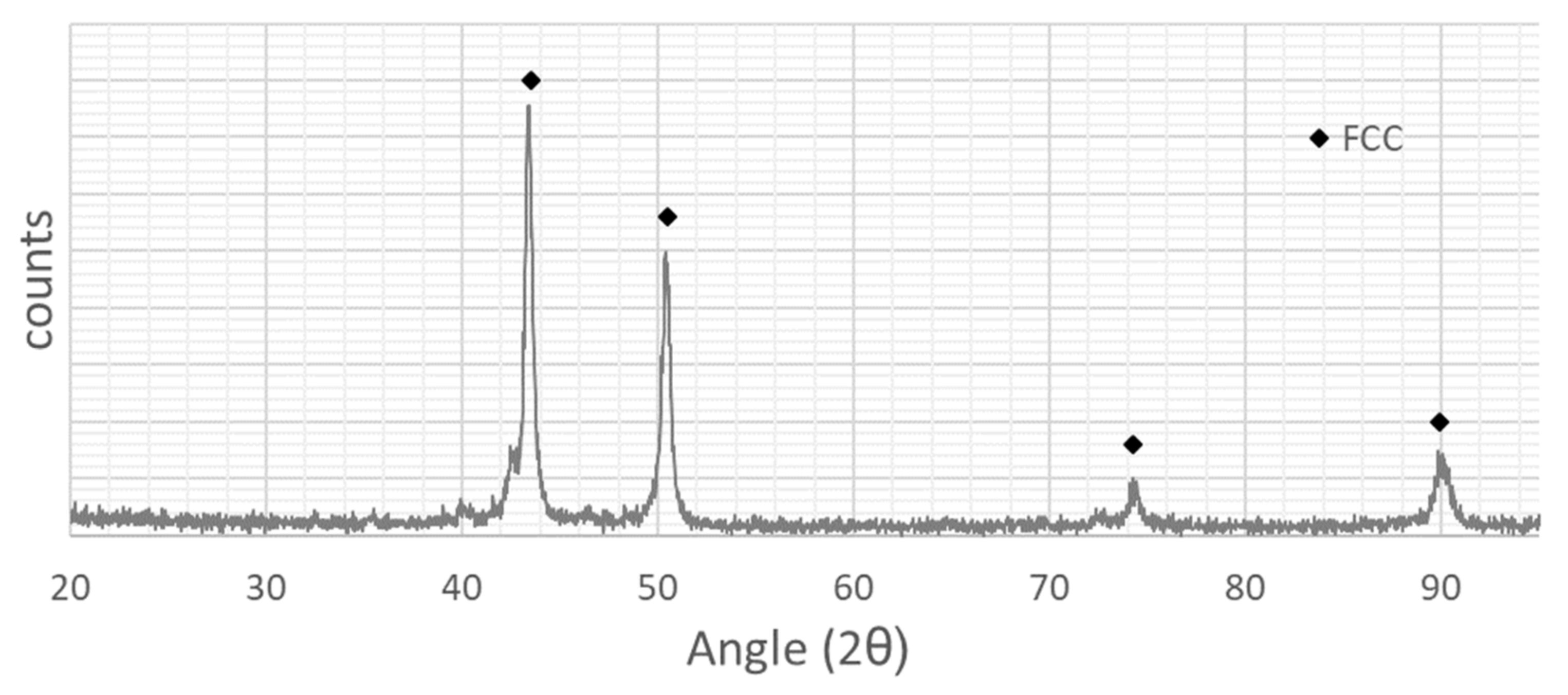
Figure 10 shows the XRD data of the alloy. These were determined on a polished piece of the material not used for other samples. The XRD data suggest a face-centered cubic crystal structure. The position of the peaks is comparable to those of the face-cantered cubic Cantor alloy from [
42,
43]. A second phase with a different lattice structure is not evident from the data. A pronounced directionality of the lattice structure was also not found.
3.5. Wear Resistance
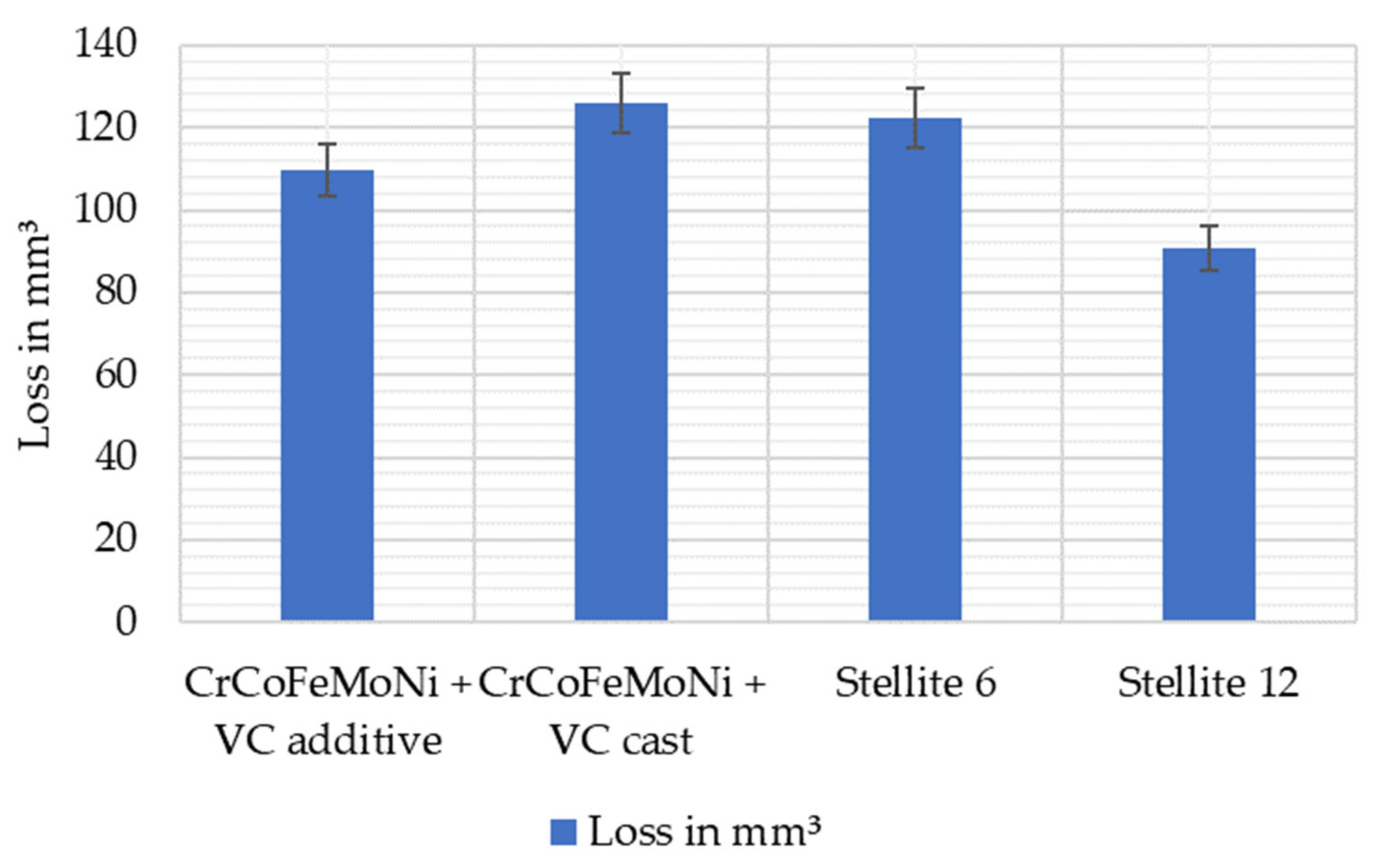
Figure 11 shows the loss of material in the G75 “Miller” test compared to the cast alloy used in [
34], and two conventional hardfacing alloys. The less material that is removed from the specimens, the better they are suited as a wear protection system against three-body abrasive wear.
The additively produced samples made of the CCA alloy show an ablation of approx. 110 mm
3 here. This means that the wear that occurs is smaller than with the cast comparative alloy and a conventionally used Stellite 6 of a cobalt–chromium alloy. Compared to the CCA, however, the second Stellite (Stellite 12) is significantly better. The Stellite specimens have been GMA-cladded [
44].
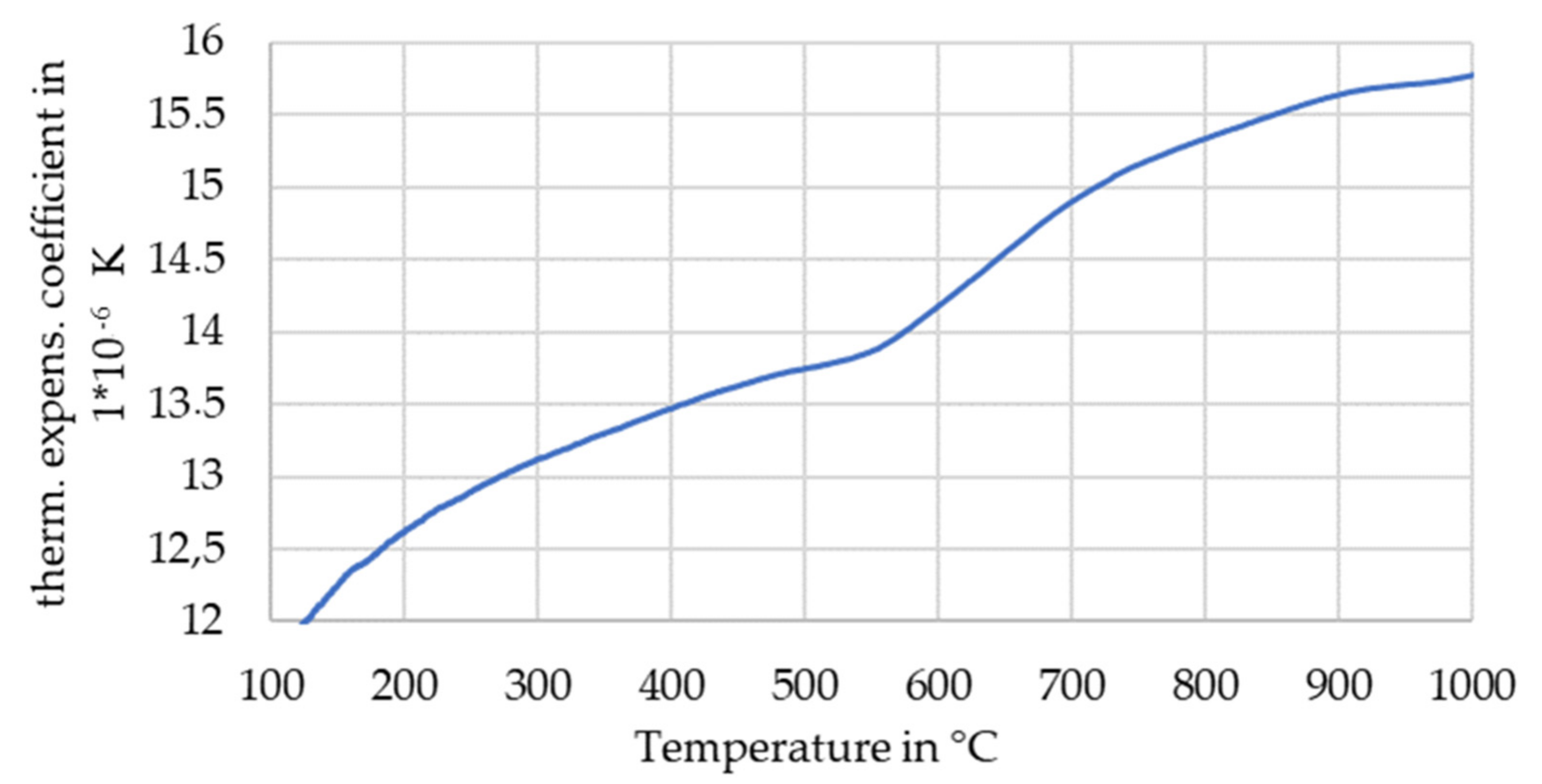
3.6. Thermal Expansion Coefficient
Figure 12 shows the thermal expansion coefficient (TCE) over the temperature for the additive manufactured complex concentrated alloy. At approx. 550 °C, the thermal expansion coefficient shows a change in behavior. After a flattening of the curve, it rises again more steeply. A similar behavior of the thermal expansion coefficient has been reported by Laplanche et al. for a CoNi alloy as well [
45]. The measured TCE over the temperature for this alloy is in a range of the literature for similar alloys [
45]. This suggests a partial or complete phase transformation of the material at 550 °C.
3.7. Density
The density of the alloy is 8.34 g/cm
3, and is thus slightly higher than that of steel. The mixing rule results in an expected density of 8.7 g/cm
3. The difference in the density can have multiple causes. First, the specimens for density measurements can include imperfections such as pores and cracks. Due to the fact that the specimen for the wear test was used to determine the density of the material, extensive porosity and cracks have not been observed. Furthermore, one of the four core effects for CCAs can be taken into account; the cocktail effect—which states that the properties of CCAs sometimes cannot be proposed by the mixing rule [
46].
4. Conclusions and Outlook
The presented results show that the usage of metal-cored fillers can be used for the additive manufacturing of CCAs. The use of metal-cored fillers allow us to significantly increase the range of possible different chemical compositions that can be investigated for their properties after arc-based additive manufacturing in comparison to the use of cable-like fillers.
Further research on the manufacturing of complex concentrated metal-cored wire, as a well-established filler for welding, needs to be done, although an alternative for alloy-development and the determination of the mechanical properties has been established using cable-like wires [
31,
32,
33].
An addition or precipitation of carbides can increase the strength and the wear resistance of an additive manufactured CCA, such as that shown in [
47]. The shown alloy composition has been chosen to promote the formation of vanadium carbide. This precipitation has been shown in previous studies for cast specimen [
34]. However, in this case, a formation of carbide has not been observed. One reason for this could be the relative low carbon content of the metal-cored filler. This will be considered in further investigations, in addition to the determination of the emerging phases of a further adjustment of the process variables.
Nevertheless, it can be said that the aim of the presented research has been achieved and the following conclusions can be drawn. The main point of the presented studies is that the usage of metal-cored wire can be used for the wire and arc additive manufacturing of complex concentrated alloys. Furthermore, the manufactured wall structure and its material has achieved the following properties:
- -
A yield strength of 534 MPa and an ultimate tensile strength of 563 MPa;
- -
An elongation of break of 2.1%;
- -
A hardness of 257 HV10.
Furthermore, the presented material has a comparable wear resistance in the G75 test to cobalt-based alloys that are currently widespread in use for wear-resistant claddings with a loss of ca. 110 mm3 of material in a standard G75 test.
In further investigations, the crystal structure of the two phases shown here will be examined in more detail. Furthermore, the quality of the deposition can be significantly increased by further adjusting the process values in additive arc-based manufacturing. Further investigations are also planned in this area. An analysis of the diffusion behavior of hydrogen in this material rounds off the planned investigations.
Author Contributions
Conceptualization, K.T. and J.H.; methodology, K.T.; validation, K.T., J.H. and V.W.; investigation, K.T.; wear tests, S.L. and J.H.; resources, V.W.; data curation, K.T.; writing—original draft preparation, K.T.; writing—review and editing, K.T., S.L., J.H. and V.W.; visualization, K.T.; material acquisition, K.T. All authors have read and agreed to the published version of the manuscript.
Funding
We acknowledge support by Open Access Publishing Fund of Clausthal University of Technology.
Data Availability Statement
Not applicable.
Acknowledgments
The authors would like to thank Durum Verschleißschutz GmbH for providing the metal-cored wires and the Institute of Non-Metallic Materials for performing the XRD measurements.
Conflicts of Interest
The authors declare no conflict of interest.
References
- Richter, T.; Arroyo, D.D.; Boerner, A.; Schroepfer, D.; Rhode, M.; Lindner, T.; Loebel, M.; Preuß, B.; Lampke, T. Ultrasonic assisted milling of a CoCrFeNi medium entropy alloy. Procedia CIRP 2022, 108, 879–884. [Google Scholar] [CrossRef]
- Yeh, J.-W.; Chen, S.-K.; Lin, S.-J.; Gan, J.-Y.; Chin, T.-S.; Shun, T.-T.; Tsau, C.-H.; Chang, S.-Y. Nanostructured High-Entropy Alloys with Multiple Principal Elements: Novel Alloy Design Concepts and Outcomes. Adv. Eng. Mater. 2004, 6, 299–303. [Google Scholar] [CrossRef]
- Cantor, B.; Chang, I.T.H.; Knight, P.; Vincent, A.J.B. Microstructural development in equiatomic multicomponent alloys. Mater. Sci. Eng. A 2004, 375–377, 213–218. [Google Scholar] [CrossRef]
- Chen, S.; Tong, Y.; Liaw, P.K. Additive Manufacturing of High-Entropy Alloys: A Review. Entropy 2018, 20, 937. [Google Scholar] [CrossRef] [PubMed] [Green Version]
- Cui, W.; Zhang, X.; Liou, F. Additive Manufacturing of High-Entropy Alloys—A Review; University of Texas at Austin: Austin, TX, USA, 2017. [Google Scholar]
- Kim, J.; Wakai, A.; Moridi, A. Materials and manufacturing renaissance: Additive manufacturing of high-entropy alloys. J. Mater. Res. 2020, 35, 1963–1983. [Google Scholar] [CrossRef]
- Chew, Y.; Bi, G.J.; Zhu, Z.G.; Ng, F.L.; Weng, F.; Liu, S.B.; Nai, S.M.L.; Lee, B.Y. Microstructure and enhanced strength of laser aided additive manufactured CoCrFeNiMn high entropy alloy. Mater. Sci. Eng. A 2019, 744, 137–144. [Google Scholar] [CrossRef]
- Dong, B.; Wang, Z.; Pan, Z.; Muránsky, O.; Shen, C.; Reid, M.; Wu, B.; Chen, X.; Li, H. On the development of pseudo-eutectic AlCoCrFeNi2.1 high entropy alloy using Powder-bed Arc Additive Manufacturing (PAAM) process. Mater. Sci. Eng. A 2021, 802, 140639. [Google Scholar] [CrossRef]
- Torralba, J.M.; Campos, M. High Entropy Alloys Manufactured by Additive Manufacturing. Metals 2020, 10, 639. [Google Scholar] [CrossRef]
- Melia, M.A.; Whetten, S.R.; Puckett, R.; Jones, M.; Heiden, M.J.; Argibay, N.; Kustas, A.B. High-throughput additive manufacturing and characterization of refractory high entropy alloys. Appl. Mater. Today 2020, 19, 100560. [Google Scholar] [CrossRef]
- Norrish, J.; Polden, J.; Richardson, I. A review of wire arc additive manufacturing: Development, principles, process physics, implementation and current status. J. Phys. D Appl. Phys. 2021, 54, 473001. [Google Scholar] [CrossRef]
- Wu, B.; Pan, Z.; Ding, D.; Cuiuri, D.; Li, H.; Xu, J.; Norrish, J. A review of the wire arc additive manufacturing of metals: Properties, defects and quality improvement. J. Manuf. Process. 2018, 35, 127–139. [Google Scholar] [CrossRef]
- Treutler, K.; Wesling, V. The Current State of Research of Wire Arc Additive Manufacturing (WAAM): A Review. Appl. Sci. 2021, 11, 8619. [Google Scholar] [CrossRef]
- Schroepfer, D.; Treutler, K.; Boerner, A.; Gustus, R.; Kannengiesser, T.; Wesling, V.; Maus-Friedrichs, W. Surface finishing of hard-to-machine cladding alloys for highly stressed components. Int. J. Adv. Manuf. Technol. 2021, 114, 1427–1442. [Google Scholar] [CrossRef]
- Evjemo, L.D.; Langelandsvik, G.; Moe, S.; Danielsen, M.H.; Gravdahl, J.T. Wire-arc additive manufacturing of structures with overhang: Experimental results depositing material onto fixed substrate. CIRP J. Manuf. Sci. Technol. 2022, 38, 186–203. [Google Scholar] [CrossRef]
- Wesling, V.; Leicher, M.; Gräbner, M.; Treutler, K.; Lorenz, S.; Esderts, A.; Hupka, M.; Wächter, M.; Spitzer, K.-H. Werkstoffkennwerte additiv gefertigter Strukturen. In 4. Symposium Materialtechnik, 25. bis 26. February 2021; Shaker Verlag: Düren, Germany, 2021. [Google Scholar] [CrossRef]
- Treutler, K.; Kamper, S.; Leicher, M.; Bick, T.; Wesling, V. Multi-Material Design in Welding Arc Additive Manufacturing. Metals 2019, 9, 809. [Google Scholar] [CrossRef] [Green Version]
- Leicher, M.; Kamper, S.; Treutler, K.; Wesling, V. Multi-material design in additive manufacturing—Feasibility validation. Weld. World 2020, 64, 1341–1347. [Google Scholar] [CrossRef]
- Kannan, A.R.; Kumar, S.M.; Kumar, N.P.; Shanmugam, N.S.; Vishnu, A.S.; Palguna, Y. Process-microstructural features for tailoring fatigue strength of wire arc additive manufactured functionally graded material of SS904L and Hastelloy C-276. Mater. Lett. 2020, 274, 127968. [Google Scholar] [CrossRef]
- Rodrigues, T.A.; Bairrão, N.; Farias, F.W.C.; Shamsolhodaei, A.; Shen, J.; Zhou, N.; Maawad, E.; Schell, N.; Santos, T.G.; Oliveira, J.P. Steel-copper functionally graded material produced by twin-wire and arc additive manufacturing (T-WAAM). Mater. Des. 2022, 213, 110270. [Google Scholar] [CrossRef]
- Marinelli, G.; Martina, F.; Lewtas, H.; Hancock, D.; Ganguly, S.; Williams, S. Functionally graded structures of refractory metals by wire arc additive manufacturing. Sci. Technol. Weld. Join. 2019, 24, 495–503. [Google Scholar] [CrossRef] [Green Version]
- Hauser, T.; Reisch, R.T.; Seebauer, S.; Parasar, A.; Kamps, T.; Casati, R.; Volpp, J.; Kaplan, A.F.H. Multi-Material Wire Arc Additive Manufacturing of low and high alloyed aluminium alloys with in-situ material analysis. J. Manuf. Process. 2021, 69, 378–390. [Google Scholar] [CrossRef]
- Madhuri, N.; Jayakumar, V.; Sathishkumar, M. Recent developments and challenges accompanying with wire arc additive manufacturing of Mg alloys: A review. Mater. Today Proc. 2021, 46, 8573–8577. [Google Scholar] [CrossRef]
- Chandrasekaran, S.; Hari, S.; Amirthalingam, M. Functionally graded materials for marine risers by additive manufacturing for high-temperature applications: Experimental investigations. Structures 2022, 35, 931–938. [Google Scholar] [CrossRef]
- Li, Y.; Feng, Z.; Hao, L.; Huang, L.; Xin, C.; Wang, Y.; Bilotti, E.; Essa, K.; Zhang, H.; Li, Z.; et al. A Review on Functionally Graded Materials and Structures via Additive Manufacturing: From Multi-Scale Design to Versatile Functional Properties. Adv. Mater. Technol. 2020, 5, 1900981. [Google Scholar] [CrossRef]
- Rosli, N.A.; Alkahari, M.R.; Abdollah, M.F.B.; Maidin, S.; Ramli, F.R.; Herawan, S.G. Review on effect of heat input for wire arc additive manufacturing process. J. Mater. Res. Technol. 2021, 11, 2127–2145. [Google Scholar] [CrossRef]
- Wächter, M.; Leicher, M.; Hupka, M.; Leistner, C.; Masendorf, L.; Treutler, K.; Kamper, S.; Esderts, A.; Wesling, V.; Hartmann, S. Monotonic and Fatigue Properties of Steel Material Manufactured by Wire Arc Additive Manufacturing. Appl. Sci. 2020, 10, 5238. [Google Scholar] [CrossRef]
- Shiran, M.R.K.G.; Bakhtiari, H.; Mousavi, S.A.-A.A.; Khalaj, G.; Mirhashemi, S.M. Effect of Stand-Off Distance on the Mechanical and Metallurgical Properties of Explosively Bonded 321 Austenitic Stainless Steel—1230 Aluminum Alloy Tubes. Mater. Res. 2017, 20, 291–302. [Google Scholar] [CrossRef] [Green Version]
- Pouraliakbar, H.; Khalaj, G.; Jandaghi, M.R.; Fadaei, A.; Ghareh-Shiran, M.K.; Shim, S.H.; Hong, S.I. Three-layered SS321/AA1050/AA5083 explosive welds: Effect of PWHT on the interface evolution and its mechanical strength. Int. J. Press. Vessel. Pip. 2020, 188, 104216. [Google Scholar] [CrossRef]
- Rhode, M.; Richter, T.; Schroepfer, D.; Manzoni, A.M.; Schneider, M.; Laplanche, G. Welding of high-entropy alloys and compositionally complex alloys—An overview. Weld. World 2021, 65, 1645–1659. [Google Scholar] [CrossRef]
- Shen, Q.; Kong, X.; Chen, X. Significant transitions of microstructure and mechanical properties in additively manufactured Al–Co–Cr–Fe–Ni high-entropy alloy under heat treatment. Mater. Sci. Eng. A 2021, 815, 141257. [Google Scholar] [CrossRef]
- Shen, Q.; Kong, X.; Chen, X. Fabrication of bulk Al-Co-Cr-Fe-Ni high-entropy alloy using combined cable wire arc additive manufacturing (CCW-AAM): Microstructure and mechanical properties. J. Mater. Sci. Technol. 2021, 74, 136–142. [Google Scholar] [CrossRef]
- Osintsev, K.; Konovalov, S.; Zaguliaev, D.; Ivanov, Y.; Gromov, V.; Panchenko, I. Investigation of Co-Cr-Fe-Mn-Ni Non-Equiatomic High-Entropy Alloy Fabricated by Wire Arc Additive Manufacturing. Metals 2022, 12, 197. [Google Scholar] [CrossRef]
- Treutler, K.; Lorenz, S.; Wesling, V. Re-Melting Behaviour and Wear Resistance of Vanadium Carbide Precipitating Cr27.5Co14Fe22Mo22Ni11.65V2.85 High Entropy Alloy. Materials 2021, 14, 1871. [Google Scholar] [CrossRef] [PubMed]
- Lin, Z.; Goulas, C.; Ya, W.; Hermans, M.J.M. Microstructure and Mechanical Properties of Medium Carbon Steel Deposits Obtained via Wire and Arc Additive Manufacturing Using Metal-Cored Wire. Metals 2019, 9, 673. [Google Scholar] [CrossRef] [Green Version]
- Béraud, N.; Chergui, A.; Limousin, M.; Villeneuve, F.; Vignat, F. An indicator of porosity through simulation of melt pool volume in aluminum wire arc additive manufacturing. Mech. Ind. 2022, 23, 1. [Google Scholar] [CrossRef]
- DIN EN ISO 6892-1:2020-06; Metallische Werkstoffe_-Zugversuch_-Teil_1: Prüfverfahren bei Raumtemperatur (ISO_6892-1:2019). Beuth Verlag GmbH: Berlin, Germany, 2020.
- DIN EN ISO 6507-1:2018-07; Metallische Werkstoffe_-Härteprüfung nach Vickers_-Teil_1: Prüfverfahren (ISO_6507-1:2018). Beuth Verlag GmbH: Berlin, Germany, 2018.
- DIN 50125:2016-12; Prüfung metallischer Werkstoffe_-Zugproben. Beuth Verlag GmbH: Berlin, Germany, 2016.
- G02 Committee. Test Method for Determination of Slurry Abrasivity (Miller Number) and Slurry Abrasion Response of Materials (SAR Number); ASTM International: West Conshohocken, PA, USA.
- Lorenz, S. Eisenbasierte intermetallische Hartlegierungen für den Verschleißschutz am Beispiel von Einschneckenextrudern. Ph.D. Thesis, Technische Universität Clausthal, Clausthal-Zellerfeld, Germany, 2019. [Google Scholar]
- Jadhav, M.S.; Sahane, D.; Verma, A.; Singh, S. Thermal stability and thermal expansion behavior of FeCoCrNi2Al high entropy alloy. Adv. Powder Technol. 2021, 32, 378–384. [Google Scholar] [CrossRef]
- Gianelle, M.A.; Clapp, C.; Kundu, A.; Chan, H.M. Solid state processing of the cantor derived alloy CoCrFeMnNi by oxide reduction. Results Mater. 2022, 14, 100286. [Google Scholar] [CrossRef]
- Lau, L.; Beuth, D.; Stenzel, P.; Wesling, V.; Reiter, R.; Lorenz, S. Kobalt- und Kobaltersatzlegierungen zum schweißtechnischen Auftragen. In DVS Congress 2016 Grosse Schweisstechnische Tagung DVS-Studentenkongress: Vorträge der Veranstaltung in Leipzig am 19. 8 und 20. September 2016; DVS Media: Düsseldorf, Germany, 2016; ISBN 978-3-945023-74-7. [Google Scholar]
- Laplanche, G.; Gadaud, P.; Bärsch, C.; Demtröder, K.; Reinhart, C.; Schreuer, J.; George, E.P. Elastic moduli and thermal expansion coefficients of medium-entropy subsystems of the CrMnFeCoNi high-entropy alloy. J. Alloys Compd. 2018, 746, 244–255. [Google Scholar] [CrossRef]
- Miracle, D.B. High-Entropy Alloys: A Current Evaluation of Founding Ideas and Core Effects and Exploring “Nonlinear Alloys”. JOM 2017, 69, 2130–2136. [Google Scholar] [CrossRef] [Green Version]
- Li, J.; Xiang, S.; Luan, H.; Amar, A.; Liu, X.; Lu, S.; Zeng, Y.; Le, G.; Wang, X.; Qu, F.; et al. Additive manufacturing of high-strength CrMnFeCoNi high-entropy alloys-based composites with WC addition. J. Mater. Sci. Technol. 2019, 35, 2430–2434. [Google Scholar] [CrossRef]
| Publisher’s Note: MDPI stays neutral with regard to jurisdictional claims in published maps and institutional affiliations. |
© 2022 by the authors. Licensee MDPI, Basel, Switzerland. This article is an open access article distributed under the terms and conditions of the Creative Commons Attribution (CC BY) license (https://creativecommons.org/licenses/by/4.0/).


