
Tunable Beam Splitter Based on Acoustic Binary Metagrating


1
School of Physics and Electronics, Hunan Normal University, Changsha 410081, China
2
Key Laboratory of Modern Acoustics, Department of Physics and Collaborative Innovation Center of Advanced Microstructures, Nanjing University, Nanjing 210093, China
*
Authors to whom correspondence should be addressed.
Appl. Sci. 2022, 12(8), 3758; https://doi.org/10.3390/app12083758
Submission received: 1 March 2022
/
Revised: 6 April 2022
/
Accepted: 6 April 2022
/
Published: 8 April 2022
(This article belongs to the Special Issue Recent Advance in Acoustic Metamaterials)
Abstract
:As an inversely designed artificial surface, acoustic metasurfaces usually consist of subwavelength unit cells in an array configuration, exhibiting exceptional abilities in acoustic wave manipulation. In contrast to metasurfaces with subwavelength units and complex configurations, we propose here a comprehensive concept of a beam splitter based on an acoustic binary metagrating (ABM), capable of splitting a given acoustic wave into two predesigned directions. The ABM is composed of only two kinds of elements, corresponding to the elements “0” and “1”, respectively. The diffraction orders in the ABM take a value of n = −1 (split beam 1) and n = 1 (split beam 2), and hence, the beam splitting occurs. We exemplify the ABM by etching only one straight-walled groove per period on a planar hard surface. In our design, the reflected angles of these two split beams can be readily controlled by setting a proper incident angle. Theoretical analysis and numerical simulations were undertaken to provide the proof of concept for the proposed acoustic beam splitter.
1. Introduction
In the field of material physics and engineering, acoustic metasurfaces have recently grown rapidly and gained widespread attention, leading to a number of unique functionalities which cannot be realized by conventional materials, such as asymmetric acoustic transmission [1,2,3], asymmetric acoustic retroflection [4,5,6], acoustic holography [7], and anomalous beam splitters [8]. An acoustic metasurface is an inversely artificial surface composed of subwavelength unit cells in an array configuration. The design of an acoustic metasurface can be divided into three steps. First, the continuous amplitude and phase distribution on the metasurface should be derived from the incident and the target pressure fields. Then, the discontinuity should be introduced to the metasurface and the discrete amplitude and phase distribution on the metasurface should be obtained. Finally, the discrete amplitude and phase distribution should be established through an elaborate arrangement of subwavelength unit cells on the metasurface.
An important methodology used to design the phase shift in a subwavelength unit cell is coiling up the space. In a space-coiling unit cell, sound waves propagate along a zigzag deep subwavelength path instead of in a straight line, such that the space is effectively coiled up in the total path length, such as in the rectangular-structured labyrinthine cell [9,10,11,12,13], the tapered labyrinthine cell [14,15], the helical-structured labyrinthine cell [16], and the coating unit cell [7]. In addition, the hybrid structure exhibits a wide range of phase shift [17,18], which consists of deep subwavelength cavities combined with a straight pipe at the open side of the deep subwavelength cavities. Here, the phase shift is induced by the series connection of Helmholtz resonators acting as the lumped elements. They provide an effective acoustic reactance to shift the phase of the incident waves. An important methodology to design the amplitude shift in a subwavelength unit cell using a perforated panel has also been proposed, which provides full amplitude control [7]. Although the metasurfaces established by such subwavelength unit cells give rise to a lot of intriguing functionalities in acoustics, they are constructed by the multi-folded channels or multi-connected cavities of a deep subwavelength scale. In other words, they suffer from elaborated configurations, and inevitable loss and deformation effects.
In this paper, we propose a comprehensive concept of a beam splitter based on an acoustic binary metagrating (ABM). Compared to the labyrinthine cell and the hybrid structure, the ABM proposed here is constructed by etching only one straight-walled groove per period on a planar hard surface. This gives rise to the reduced intrinsic loss and easy fabrication. The binary reflected phases on planar surface have been proposed to realize the broadband convergence of acoustic energy [19]. Here, the diffraction orders in the proposed ABM take a value of n = −1 (split beam 1) and n = 1 (split beam 2), and hence, the beam splitting occurs. In our design, the directions of the split beams can be readily controlled by setting a proper incident angle. Theoretical analysis and numerical simulations were undertaken to provide the proof of concept for the proposed acoustic beam splitter. In the proposed ABM, the beam splitting occurs in a wide range when the period length a is in the range of and the incident angle is in the range of . Here, a is the period length in the ABM, and is the operating wavelength in the air.
2. Materials and Methods
Figure 1a shows the schematic illustration of the proposed ABM. It consists of only two different elements, “0” and “1”, compactly arranged along the x direction, providing the binary phase shifts of 0 and π, respectively. Here, the length of the element “0” or “1” is t, and the period length in the ABM is . When a given acoustic wave arrives at the ABM, it is split into two predesigned directions: beam 1 (−x direction) and beam 2 (+x direction). A general grating theory is provided here to demonstrate the physical mechanism underlying the beam splitting. When the acoustic waves impinge on the ABM with the incident angle of , the reflected waves should follow the grating Equation [1,3]:
where is the wave number in the air, is the operating wavelength in the air, is the reflected angle, n is the diffraction order (integer), and is the reciprocal lattice vector.
As depicted in Figure 1b, for the normal incidence of , by limiting , it can be derived from Equation (1) that only the range of , corresponding to , may give rise to the target pressure field. In the target pressure field, only the diffracted waves of the orders of n = 0, n = −1, and n = 1 are the propagating waves. The diffraction order in the ABM taking a value of n = −1 corresponds to the split beam 1 (−x direction), n = 1 corresponds to the split beam 2 (+x direction), and hence, the beam splitting occurs. In addition to the filter of the redundant diffracted waves by choosing the reciprocal lattice vector , i.e., period length a in the ABM, the specular reflection of n = 0 should also be totally suppressed here to realize the beam splitting.
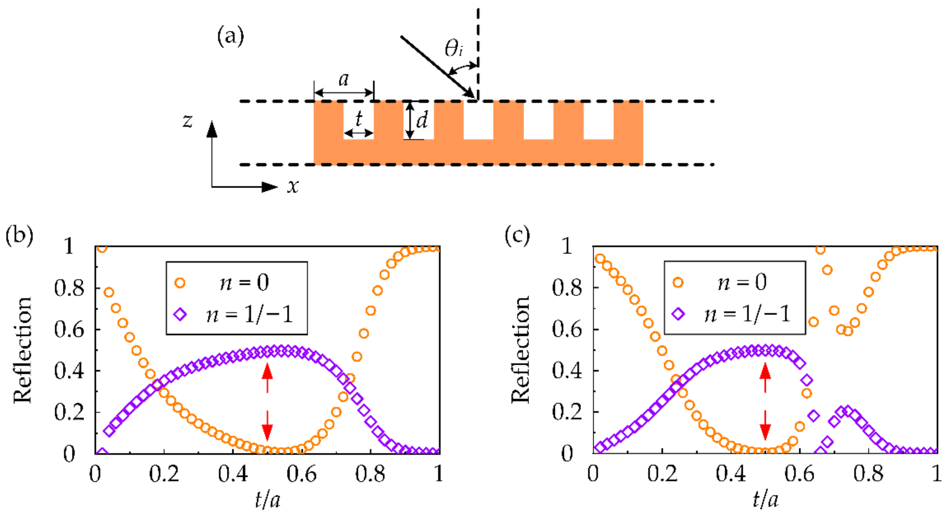
The structure we proposed to construct the ABM is schematically illustrated in Figure 2a, which is a planar hard surface having pitch a in the x direction. In each period, only one straight-walled groove is etched on the planar hard surface. The depth and width of the groove in each period are denoted as t and d, respectively. The region of the hard surface provides no phase shift of the incident waves, corresponding to the element “0”. Thus, to construct an ABM, the region of the groove should provide the phase shift of , corresponding to the element “1”. Since the phase delay is after the incident waves propagating along a round trip in the groove, the phase shift of can be provided with the groove of the depth .
Now we optimize the geometrical parameter of the groove width t in the ABM. A series of numerical simulations were performed to calculate the reflection of the diffracted waves of n = 0, n = −1, and n = 1 as a function of the ratio t/a. Here, the full wave simulations based on the finite-element analysis were performed using the COMSOL Multiphysics electromagnetic waves module. Equivalence between acoustics and electromagnetics (TM polarization) in the two-dimensional systems should be used. To clarify this equivalence, Maxwell’s equations are presented:
where and are the parameters of permittivity and permeability, respectively. is the angular frequency. is the electric field. is the magnetic field. For the two-dimensional electromagnetic wave (TM polarization) in the x-z plane of , the corresponding parameters are . Considering the harmonic factor , there are:
Acoustic wave equations are expressed as:
where is the pressure. is the velocity. is the angular frequency. is the mass density. is the bulk modulus. For the two-dimensional acoustic wave in the x-z plane of , the corresponding parameters are . Considering the harmonic factor , there are:
By comparizing the Equations (6)–(9) of the electromagnetic wave in the x-z plane and the Equations (12)–(14) of the acoustic wave in the x-z plane, the equivalence can be derived as shown in Table 1 [20,21,22].
For the isotropic medium of air, there are and . The parameters of density , bulk modulus B, and pressure P in acoustics are equivalent to the parameters of permittivity ε, reciprocal permeability , and magnetic field component in electromagnetics (TM polarization), respectively. Thus, the material parameters in the COMSOL Multiphysics electromagnetic waves module are set as and . Here, is the relative permittivity, is the relative permeability, is the permittivity of vacuum, is the permeability of vacuum. is the mass density in the air. is the bulk modulus in the air. is the sound velocity in the air.
In the COMSOL Multiphysics electromagnetic waves module, the numerical model as shown in Figure 3 is used. The top boundary is set as the period port with the wave excitation on. The input quantity is the magnetic field (0, 0, 1). It should be noted that in our proposal, the two-dimensional system is the x-z plane [see Figure 2a], whereas in the numerical model of COMSOL Multiphysics, the two-dimensional system is the x-y plane [see Figure 3]. Thus, the magnetic field (0, 0, 1) in the numerical model corresponds to (0, 1, 0) in our proposal, i.e., . The angle of incidence is set as 0 (normal incidence). Two diffraction orders are added at this port with the in-plane vector of m = −1 and m = 1. The left and right boundaries are set as the period condition, with the Floquet periodicity from the periodic port. The bottom boundary is set as the perfect electric conductor, which is analogous to the sound hard boundary in acoustics [20,21,22]. The reflection as a function of the ratio t/a in the case of is calculated and shown in Figure 2b. The reflection as a function of the ratio t/a in the case of is calculated and shown in Figure 2c. In the two cases, it is noted that when t/a = 0.5 (marked by the red arrows), there are and , which correspond to the beam splitting. When a given acoustic wave (normal incidence of ) arrives at the ABM, it is split into two predesigned directions of the diffracted waves of n = −1 (split beam 1, −x direction) and n = 1 (split beam 2, +x direction), and the specular reflection of the diffracted wave of n = 0 is totally suppressed. In other words, when the widths of the element “0” and the element “1” are equal to each other, the beam splitting occurs.
Such a structure can be demonstrated by the general grating theory. When the acoustic waves impinge on the ABM with the incident angle of , the total pressure field above the ABM can be expressed as [1,3,8]:
where is the reflection coefficient of the n-th order diffracted waves. is the wave number component in the z direction for the n-th order diffracted waves. The pressure field in the grooves can be expressed as the superposition of the waveguide modes as:
where is the amplitude of the m-th order waveguide mode. and are the wave number component of the m-th waveguide mode in the x and z directions, respectively.
The velocity fields are then obtained from . Here, and are the mass density of the air and the angular frequency of the waves, respectively. By using the continuum condition for the pressure field P and the surface-normal velocity field at the interface z = 0, the following equations relating the coefficients and can be obtained:
and:
For the ABM in the case of , the reflections with the normal incidence () can be derived from Equations (17) and (18) that and . For the ABM in the case of , the reflections with the normal incidence () can be derived from Equations (17) and (18) that and . Here, , and are the reflections of the diffracted waves of the orders n = 0, n = −1 and n = 1, respectively. It is noted that the reflection of the 0-th order diffracted waves is extremely small, and thus, the dominant propagating modes are the diffracted waves of n = −1 and n = 1. In other words, the specular reflection is totally suppressed and the beam splitting occurs.
3. Results
Here, how the incident angle affects the beam splitting is investigated. It can be derived from the Equation (1) that . As the geometrical structure of the proposed ABM is symmetric in the x direction, the range of the incident angle of is investigated. It should be emphasized that the key to realize the beam splitting is that the dominant propagating modes are the diffracted waves of n = −1 and n = 1. Since the reflection of the diffracted waves of n = 0 (specular reflection) is extremely small, by limiting for n = −1 and n = 1, the possible range of the incident angle for the beam splitting can be derived that .
The numerical simulations were performed to verify the mechanism on the beam splitting in the ABM. Figure 4 shows the case of . The possible range of the incident angle for the beam splitting can be derived that . The depth and width of the groove in each period are t = 0.5a and , respectively. The operating wavelength is set as . Here, the full wave simulations based on finite-element analysis were performed using the COMSOL Multiphysics pressure acoustics module. The plane-wave radiation boundary condition is used on the top boundary. The sound hard boundary condition is used on the bottom boundary. The background pressure field is used on the whole region with the incident angle of , , and . The scattering pressure field distributions with the incident angle of , , and are shown in Figure 4a–c, respectively. The white arrows show the directions of the incident and the reflected waves. The polar plots of the normalized intensity of the scattering waves in the exterior field with the incident angle of , , and are shown in Figure 4d–f, respectively. Here, is the normalized intensity of the scattering waves as a function of the reflected angle. All the intensities are normalized to the maximal intensity of the scattering waves of the normal incidence. It is noted that the beam splitting effects are obvious. For all these incident angles, when a given acoustic wave arrives at the ABM, it is split into two predesigned directions: split beam 1 (−x direction) and split beam 2 (+x direction). With the increase in the oblique incident angle, the reflected angle of the split beam 1 (−x direction) decreases gradually, while the reflected angle of the split beam 2 (+x direction) increases gradually.
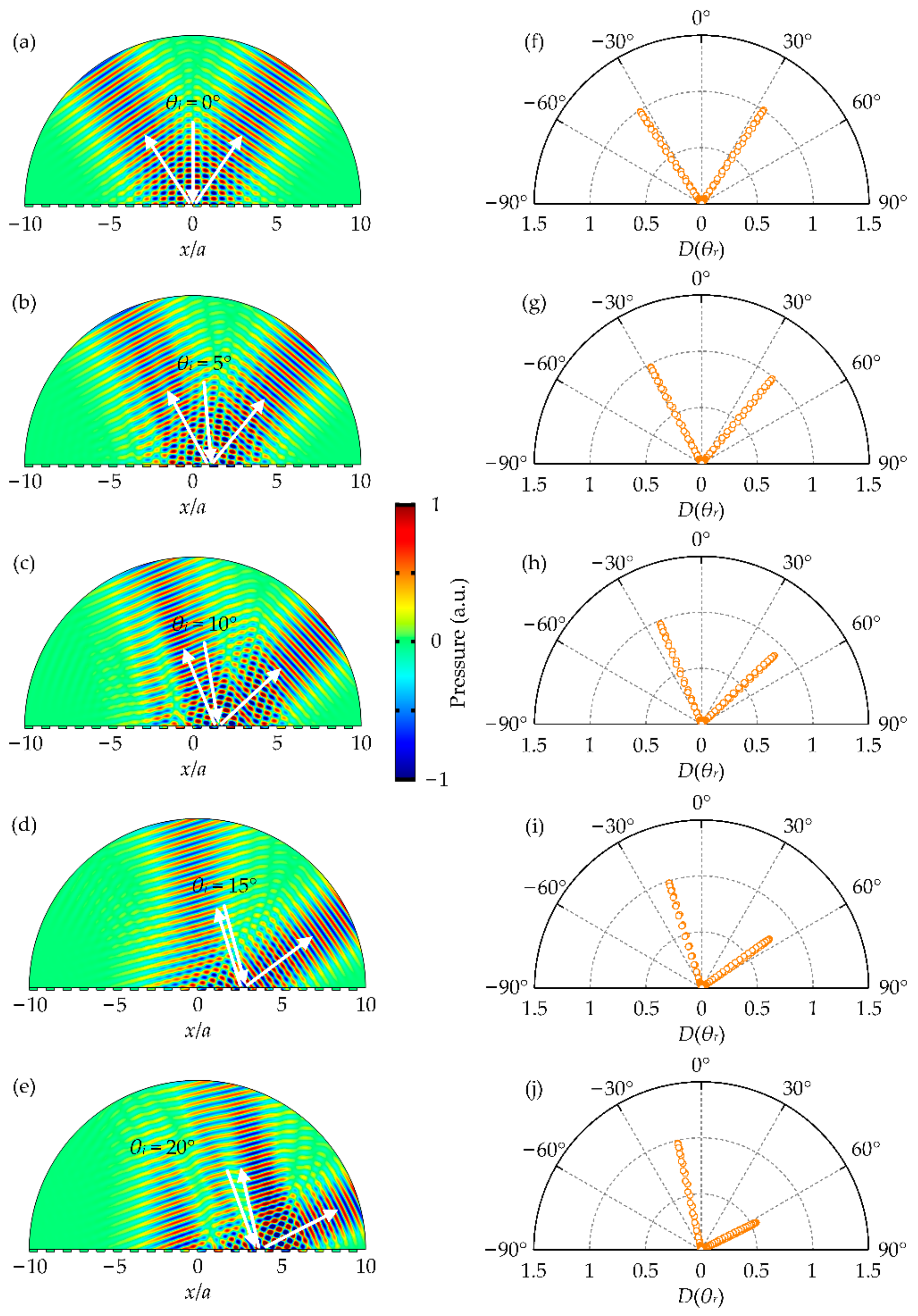
Figure 5 shows the case of . The possible range of the incident angle for the beam splitting can be derived that . The depth and width of the groove in each period are t = 0.5a and , respectively. The operating wavelength is set as . Here, the full wave simulations based on finite-element analysis were performed using the COMSOL Multiphysics pressure acoustics module. The plane–wave radiation boundary condition is used on the top boundary. The sound hard boundary condition is used on the bottom boundary. The background pressure field is used on the whole region with the incident angle of , , , , and . The scattering pressure field distributions with the incident angle of , , , , and are shown in Figure 5a–e, respectively. The white arrows show the directions of the incident and the reflected waves. The polar plots of the normalized intensity of the scattering waves in the exterior field with the incident angle of , , , , and are shown in Figure 5f–j, respectively. It is noted that the beam splitting effects are obvious. For all these incident angles, when a given acoustic wave arrives at the ABM, it is split into two predesigned directions: split beam 1 (−x direction) and split beam 2 (+x direction). With the increase in the oblique incident angle, the reflected angle of the split beam 1 (−x direction) decreases gradually, while the reflected angle of the split beam 2 (+x direction) increases gradually. It should be noted that in the range of , there is for n = −2. In other words, in addition to the diffraction orders of n = 0, n = −1 and n = 1, the diffraction order of n = −2 also corresponds to the propagating waves in the case of . However, as shown in Figure 5h–j, no intensity distribution of the diffracted waves of n = −2 is noted. Thus, the beam splitting occurs in the incident angle range of .
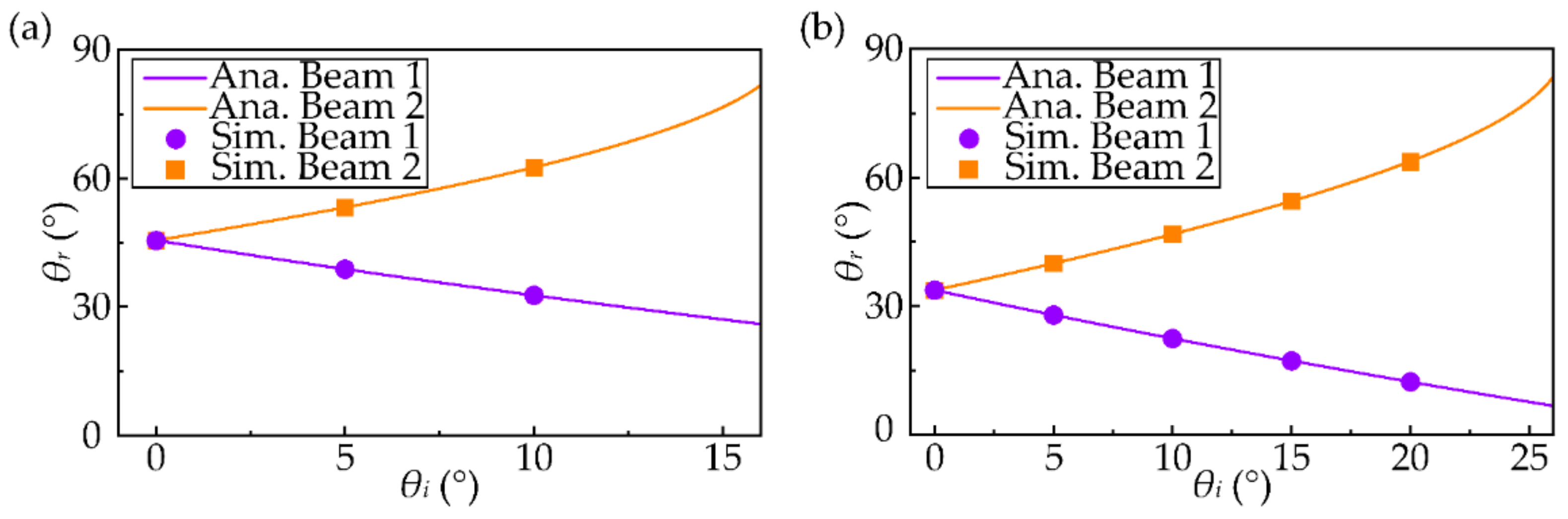
The reflected angle as a function of the incident angle is also investigated. Figure 6a shows the case of . For the split beam 1 (−x direction), the reflected angle decreases from 45.6° to 26.0° when the incident angle increases from 0° to 16°. For the split beam 2 (+x direction), the reflected angle increases from 45.6° to 81.9° when the incident angle increases from 0° to 16°. Figure 6b shows the case of . For the split beam 1 (−x direction), the reflected angle decreases from 33.7° to 6.7° when the incident angle increases from 0° to 26°. For the split beam 2 (+x direction), the reflected angle increases from 33.7° to 83.7° when the incident angle increases from 0° to 26°. In the two cases, it is noted that the reflected angle is affected by the incident angle. Thus, the directions of the split beams can be readily controlled by setting a proper incident angle.
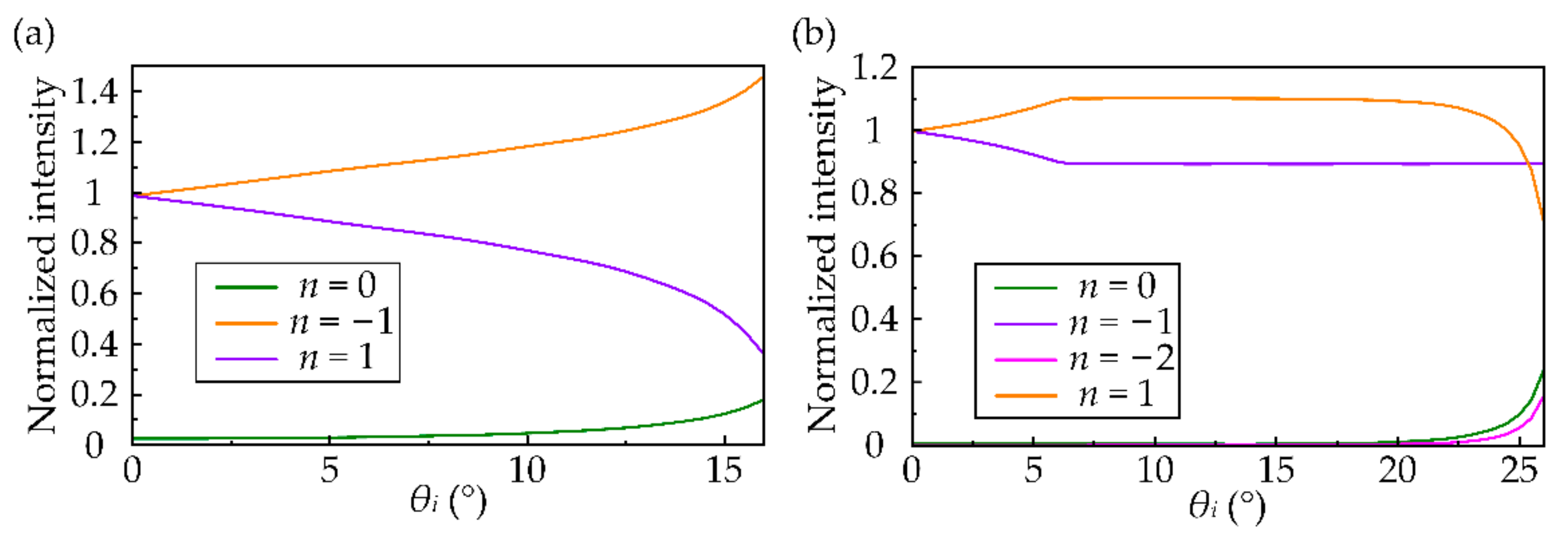
The intensity distributions of the diffracted waves of different diffraction orders as a function of the incident angle were also calculated using the COMSOL Multiphysics electromagnetic waves module. It can be derived from Equation (1) that when and the incident angle is in the range of , only the diffraction waves of n = 0, n = −1 and n = 1 give rise to the propagating waves. Figure 7a shows the normalized intensity of the corresponding diffraction orders as a function of the incident angle. All the intensities are normalized to the intensity of the split beam 1 at normal incidence. It is noted that the intensity of the split beam 1 (n = −1) gradually increases when the incident angle increases from 0 to 16. The intensity of the split beam 2 (n = 1) gradually decreases when the incident angle increases from 0 to 16. The intensity of the specular reflected beam (n = 0) is extremely small compared to the two split beams (n = −1 and n = 1). Consequently, the beam splitting occurs. It can be derived from Equation (1) that when and the incident angle is in the range of , only the diffracted waves of n = 0, n = −1, n = −2 and n = 1 give rise to the propagating waves. Figure 7b shows the normalized intensity of the corresponding diffraction orders as a function of the incident angle. All the intensities are normalized to the intensity of the split beam 1 at normal incidence. It is noted that the intensity of the diffracted waves of the high diffraction order (n = −2) and the specular reflected beam (n = 0) is extremely small compared to the two split beams (n = −1 and n = 1). Consequently, the beam splitting occurs.
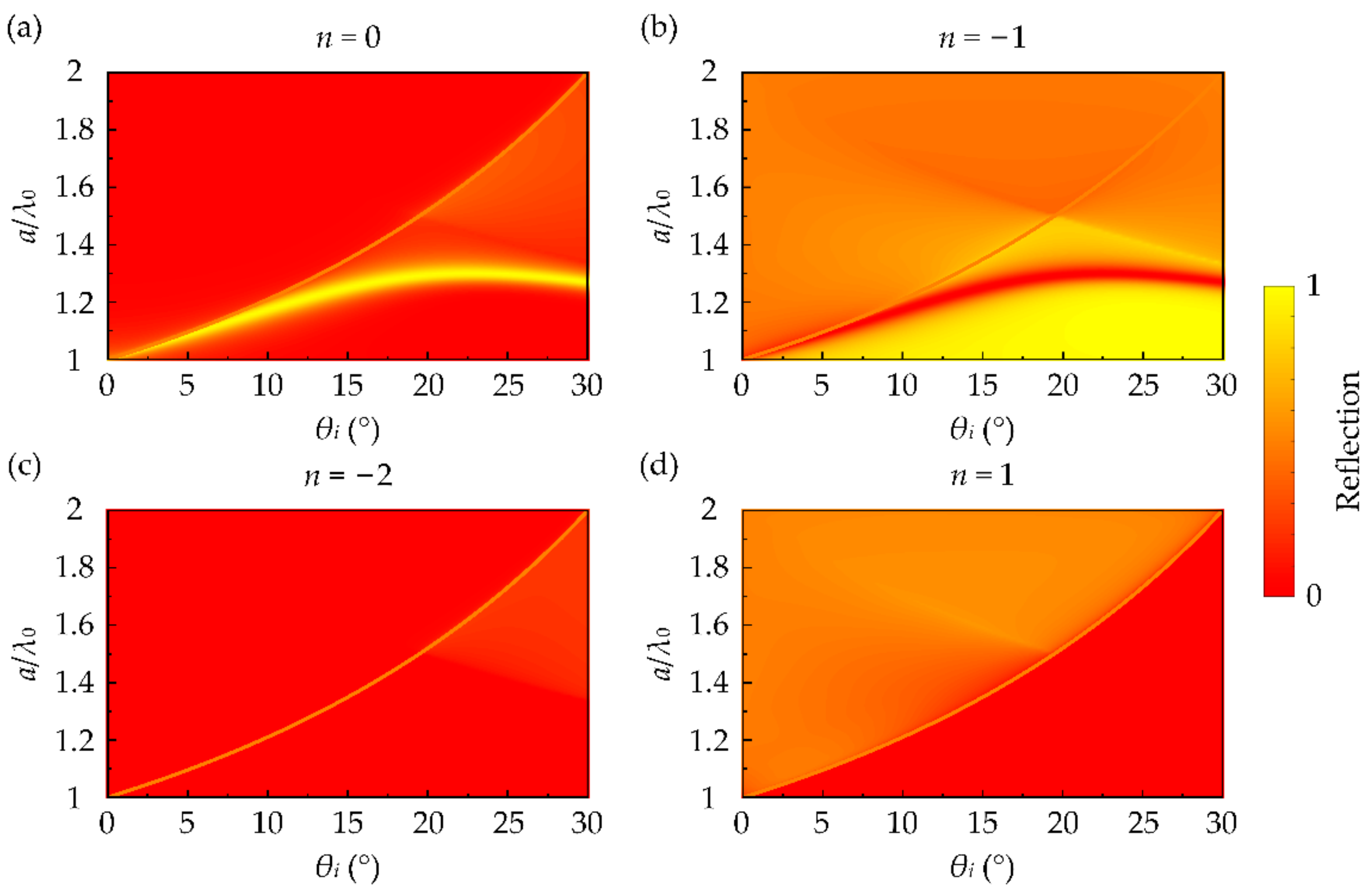
To further investigate the intensity distribution of the diffracted waves of different diffraction orders, a series of numerical simulations were performed to calculate the reflection as a function of the incident angle and the period length a using the COMSOL Multiphysics electromagnetic waves module. It can be derived from Equation (1) that when the period length a is in range of and the incident angle is in range of , only the diffraction waves of n = 0, n = −1, n = −2, and n = 1 give rise to the propagating waves. The reflection of the diffracted waves of n = 0, n = −1, n = −2, and n = 1 were calculated and are shown in Figure 8a–d, respectively. It is noted that in range of , corresponding to the left part of the orange lines, the reflection of the diffracted waves of the high diffraction order (n = −2) and the specular reflected wave (n = 0) are extremely small compared to the two split beams (n = −1 and n = 1). In other words, in the proposed ABM, the beam splitting occurs when the period length a is in range of and the incident angle is in range of .
4. Discussion
In this paper, we demonstrate the beam splitter based on the ABM, which is constructed by etching a straight-walled groove per period on the planar hard surface. This is in contrast to the typical design of the subwavelength unit cells on the acoustic metasurfaces, which are usually constructed by the multi-folded channels or multi-connected cavities of a deep subwavelength scale. The structure of the ABM in our proposal gives rise to the reduced intrinsic loss and the easy fabrication. The diffraction orders in the proposed ABM take a value of n = −1 (split beam 1, −x direction) and n = 1 (split beam 2, +x direction), and hence, the beam splitting occurs. In other words, when a given acoustic wave arrives at the ABM, it is split into two predesigned directions. In our design, the broad region of the incident angle reported here distinguishes our splitter from previous splitters using acoustic metagrating, which are designed only for the normal incidence [8]. The reflected angles of the two split beams are affected by the incident angle. Thus, the directions of the split beams can be readily controlled by setting a proper incident angle. Theoretical analysis of a general grating theory is provided here to demonstrate the physical mechanism underlying the beam splitting. Numerical simulations are provided to give the proof of concept for the proposed acoustic beam splitter. Throughout the paper, the full wave simulations based on the finite-element analysis were performed using COMSOL Multiphysics. In addition to the pressure acoustics module, the electromagnetic waves module was also used. Here, equivalence between acoustics and electromagnetics (TM polarization) in the two-dimensional systems is used. The parameters of density , bulk modulus B, and pressure P in acoustics are equivalent to the parameters of permittivity ε, reciprocal permeability , and magnetic field component in electromagnetics (TM polarization), respectively. In the proposed ABM, the beam splitting occurs when the period length a is in the range of and the incident angle is in the range of . Here, the operating wavelength is set as . Thus, the beam splitting occurs when the period length a is in the range of . In the case of , the beam splitting occurs when the incident angle is in the range of . In the case of , the beam splitting occurs when the incident angle is in the range of . We envision that the proposed beam splitter based on the ABM has potential applications in information processing and biomedical diagnostics. Our beam splitter may be applied in information processing where two positions should be provided with the sound information. For example, considering a scenario in an open and multi-functional conference room, when two regions are the listening regions, our proposed beam splitter can reflect sound along the predesigned routings and enable listening in the two regions without any disturbance in the other regions. In addition, this design may have potential applications in biomedical diagnostics involving two image targets.
5. Conclusions
In conclusion, we demonstrated the beam splitter based on the ABM, which is constructed by etching a straight-walled groove per period on the planar hard surface. The structure of the ABM in our proposal gives rise to the reduced intrinsic loss and the easy fabrication. The diffraction orders in the proposed ABM take a value of n = −1 (split beam 1) and n = 1 (split beam 2), and hence, the beam splitting occurs. In our design, the directions of the split beams can be readily controlled by setting a proper incident angle. Theoretical analysis and numerical simulations were undertaken to provide the proof of concept for the proposed acoustic beam splitter. In the proposed ABM, the beam splitting occurs when the period length a is in the range of and the incident angle is in the range of . For example, in the case of , the beam splitting occurs when . In the case of , the beam splitting occurs when . The proposed beam splitter based on the ABM may have potential applications in information processing and biomedical diagnostics.
Author Contributions
Conceptualization, Z.L. and F.J.; methodology, S.Q.; software, S.Q.; validation, Z.L., S.Q. and F.J.; writing—original draft preparation, Z.L.; writing—review and editing, F.J. and X.L.; visualization, F.J.; funding acquisition, F.J. All authors have read and agreed to the published version of the manuscript.
Funding
This research was funded by the National Natural Science Foundation of China (NSFC), grant number 12104149 and the Doctoral Science Foundation of Hunan Normal University, grant number 0531120-4222.
Institutional Review Board Statement
Not applicable.
Informed Consent Statement
Not applicable.
Data Availability Statement
Not applicable.
Conflicts of Interest
The authors declare no conflict of interest.
References
- Ju, F.; Tian, Y.; Cheng, Y.; Liu, X. Asymmetric acoustic transmission with a lossy gradient-index metasurface. Appl. Phys. Lett. 2018, 113, 121901. [Google Scholar] [CrossRef]
- Gu, Z.; Fang, X.; Liu, T.; Gao, H.; Liang, S.; Li, Y.; Liang, B.; Cheng, J.; Zhu, J. Tunable asymmetric acoustic transmission via binary metasurface and zero-index metamaterials. Appl. Phys. Lett. 2021, 118, 113501. [Google Scholar] [CrossRef]
- Li, Y.; Shen, C.; Xie, Y.; Li, J.; Wang, W.; Cummer, S.A.; Jing, Y. Tunable asymmetric transmission via lossy acoustic metasurfaces. Phys. Rev. Lett. 2017, 119, 035501. [Google Scholar] [CrossRef] [PubMed] [Green Version]
- Wang, X.; Fang, X.; Mao, D.; Jing, Y.; Li, Y. Extremely asymmetrical acoustic metasurface mirror at the exceptional point. Phys. Rev. Lett. 2019, 123, 214302. [Google Scholar] [CrossRef] [Green Version]
- Song, A.; Li, J.; Peng, X.; Shen, C.; Zhu, X.; Chen, T.; Cummer, S.A. Asymmetric absorption in acoustic metamirror based on surface impedance engineering. Phys. Rev. Appl. 2019, 12, 054048. [Google Scholar] [CrossRef]
- Ju, F.; Zou, X.; Qian, S.-Y.; Liu, X. Asymmetric acoustic retroflection with a non-Hermitian metasurface mirror. Appl. Phys. Express 2021, 14, 124001. [Google Scholar] [CrossRef]
- Tian, Y.; Wei, Q.; Cheng, Y.; Liu, X. Acoustic holography based on composite metasurface with decoupled modulation of phase and amplitude. Appl. Phys. Lett. 2017, 110, 191901. [Google Scholar] [CrossRef]
- Ni, H.; Fang, X.; Hou, Z.; Li, Y.; Assouar, B. High-efficiency anomalous splitter by acoustic meta-grating. Phys. Rev. B 2019, 100, 104104. [Google Scholar] [CrossRef] [Green Version]
- Liang, Z.; Li, J. Extreme Acoustic metamaterial by coiling up space. Phys. Rev. Lett. 2012, 108, 114301. [Google Scholar] [CrossRef]
- Qi, S.; Li, Y.; Assouar, B. Acoustic focusing and energy confinement based on multilateral metasurfaces. Phys. Rev. Appl. 2017, 7, 054006. [Google Scholar] [CrossRef]
- Zhao, S.-D.; Chen, A.L.; Wang, Y.-S.; Zhang, C. Continuously tunable acoustic metasurface for transmitted wavefront modulation. Phys. Rev. Appl. 2018, 10, 054066. [Google Scholar] [CrossRef] [Green Version]
- Yuan, B.; Cheng, Y.; Liu, X. Conversion of sound radiation pattern via gradient acoustic metasurface with space-coiling structure. Appl. Phys. Express 2015, 8, 027301. [Google Scholar] [CrossRef]
- Li, Y.; Liang, B.; Gu, Z.-M.; Zou, X.-Y.; Cheng, J.-C. Reflected wavefront manipulation based on ultrathin planar acoustic metasurfaces. Sci. Rep. 2013, 3, 2546. [Google Scholar] [CrossRef] [Green Version]
- Liu, B.; Ren, B.; Zhao, J.; Xu, X.; Feng, Y.; Zhao, W.; Jiang, Y. Experimental realization of all-angle negative refraction in acoustic gradient metasurface. Appl. Phys. Lett. 2017, 111, 221602. [Google Scholar] [CrossRef]
- Xie, Y.; Wang, W.; Chen, H.; Konneker, A.; Popa, B.-I.; Cummer, S.A. Wavefront modulation and subwavelength diffractive acoustics with an acoustic metasurface. Nat. Commun. 2014, 5, 5553. [Google Scholar] [CrossRef] [PubMed]
- Fan, S.-W.; Zhao, S.-D.; Chen, A.L.; Wang, Y.-F.; Assouar, B.; Wang, Y.-S. Tunable broadband reflective acoustic metasurface. Phys. Rev. Appl. 2019, 11, 044038. [Google Scholar] [CrossRef]
- Li, Y.; Jiang, X.; Liang, B.; Cheng, J.-C.; Zhang, L. Metascreen-based acoustic passive phased array. Phys. Rev. Appl. 2015, 4, 024003. [Google Scholar] [CrossRef]
- Jiang, X.; Li, Y.; Liang, B.; Cheng, J.-C.; Zhang, L. Convert acoustic resonances to orbital angular momentum. Phys. Rev. Lett. 2016, 117, 034301. [Google Scholar] [CrossRef]
- Fan, X.-D.; Zhu, Y.-F.; Liang, B.; Yang, J.; Cheng, J.-C. Broadband convergence of acoustic energy with binary reflected phases on planar surface. Appl. Phys. Lett. 2016, 109, 243501. [Google Scholar] [CrossRef]
- Chen, Y.; Liu, H.; Reilly, M.; Bae, H.; Yu, M. Enhanced acoustic sensing through wave compression and pressure amplification in anisotropic metamaterials. Nat. Commun. 2014, 5, 5247. [Google Scholar] [CrossRef] [Green Version]
- Li, J.; Fok, L.; Yin, X.; Bartal, G.; Zhang, X. Experimental demonstration of an acoustic magnifying hyperlens. Nat. Mater. 2009, 8, 931–934. [Google Scholar] [CrossRef] [PubMed]
- Cummer, S.A.; Schurig, D. One path to acoustic cloaking. New J. Phys. 2007, 9, 45. [Google Scholar] [CrossRef]
Figure 1.
(a) Schematic illustration of a beam splitter based on the ABM. (b) Diagram of realizing a beam splitter in the ABM. The black cross on the black arrow indicates that the specular reflection waves are totally suppressed.
Figure 1.
(a) Schematic illustration of a beam splitter based on the ABM. (b) Diagram of realizing a beam splitter in the ABM. The black cross on the black arrow indicates that the specular reflection waves are totally suppressed.

Figure 2.
(a) Schematic illustration of the proposed ABM, which is constructed by etching one straight-walled groove per period on a planar hard surface. The periodicity is along the x direction, and the period length is a. The depth and width of the groove in each period are denoted as t and d, respectively. Simulated reflection responses as a function of the ratio t/a (b) in the case of and (c) in the case of . Here, , .

Figure 3.
The numerical model to calculate the reflection of the diffracted waves of n = 0, n = −1, and n = 1 as a function of the ratio t/a performed using the COMSOL Multiphysics electromagnetic waves module.
Figure 3.
The numerical model to calculate the reflection of the diffracted waves of n = 0, n = −1, and n = 1 as a function of the ratio t/a performed using the COMSOL Multiphysics electromagnetic waves module.

Figure 4.
The case of . The scattering pressure field distributions for the beam splitting with the incident angle of (a) , (b) , and (c) . The white arrows show the directions of the incident and the reflected waves. The polar plots of the normalized intensity of the scattering waves in the exterior field with the incident angle of (d) , (e) , and (f) . The lateral axes in (d–f) are the normalized intensity defined as . All the intensities are normalized to the maximal intensity of the scattering waves of the normal incidence.

Figure 5.
The case of . The scattering pressure field distributions for the beam splitting with the incident angle of (a) , (b) , (c) (d) , and (e) . The white arrows show the directions of the incident and the reflected waves. The polar plots of the normalized intensity of the scattering waves in the exterior field with the incident angle of (f) , (g) , (h) , (i) , and (j) . The lateral axes in (f–j) are the normalized intensity defined as . All the intensities are normalized to the maximal intensity of the scattering waves of the normal incidence.

Figure 6.
Analytical and simulated results of the reflected angle at different incident angles (a) in the case of and (b) in the case of .
Figure 6.
Analytical and simulated results of the reflected angle at different incident angles (a) in the case of and (b) in the case of .

Figure 7.
Simulated results of the normalized intensity of the reflected waves at different incident angles (a) in the case of and (b) in the case of . All the intensities are normalized to the intensity of the split beam 1 at normal incidence.
Figure 7.
Simulated results of the normalized intensity of the reflected waves at different incident angles (a) in the case of and (b) in the case of . All the intensities are normalized to the intensity of the split beam 1 at normal incidence.

Figure 8.
Simulated reflection of the diffraction orders of (a) n = 0, (b) n = −1, (c) n = −2, and (d) n = 1 as a function of the incident angle and the periodicity a. Here, and . The orange lines correspond to the function of . .
Figure 8.
Simulated reflection of the diffraction orders of (a) n = 0, (b) n = −1, (c) n = −2, and (d) n = 1 as a function of the incident angle and the periodicity a. Here, and . The orange lines correspond to the function of . .


Table 1.
The equivalence between the acoustic wave and the electromagnetic wave (TM polarization).
| Acoustic Wave | Electromagnetic Wave (TM Polarization) |
|---|---|
| Mass density | Permittivity |
| Mass density | Permittivity |
| bulk modulus B | Reciprocal permeability |
| Pressure P | magnetic field component |
| Velocity field component | electric field component |
| Velocity field component | electric field component |
Publisher’s Note: MDPI stays neutral with regard to jurisdictional claims in published maps and institutional affiliations. |
© 2022 by the authors. Licensee MDPI, Basel, Switzerland. This article is an open access article distributed under the terms and conditions of the Creative Commons Attribution (CC BY) license (https://creativecommons.org/licenses/by/4.0/).
Share and Cite
MDPI and ACS Style
Liu, Z.; Ju, F.; Qian, S.; Liu, X. Tunable Beam Splitter Based on Acoustic Binary Metagrating. Appl. Sci. 2022, 12, 3758. https://doi.org/10.3390/app12083758
AMA Style
Liu Z, Ju F, Qian S, Liu X. Tunable Beam Splitter Based on Acoustic Binary Metagrating. Applied Sciences. 2022; 12(8):3758. https://doi.org/10.3390/app12083758
Chicago/Turabian StyleLiu, Zhengang, Fangfang Ju, Shengyou Qian, and Xiaojun Liu. 2022. "Tunable Beam Splitter Based on Acoustic Binary Metagrating" Applied Sciences 12, no. 8: 3758. https://doi.org/10.3390/app12083758
Note that from the first issue of 2016, this journal uses article numbers instead of page numbers. See further details here.