
Development and Performance Measurements of Gas Foil Polymer Bearings with a Dual-Rotor Test Rig Driven by Permanent Magnet Electric Motor


Department of Mechanical System Design Engineering, Seoul National University of Science and Technology, Seoul 139-743, Korea
*
Author to whom correspondence should be addressed.
Appl. Sci. 2022, 12(3), 1505; https://doi.org/10.3390/app12031505
Submission received: 20 November 2021
/
Revised: 24 January 2022
/
Accepted: 25 January 2022
/
Published: 30 January 2022
(This article belongs to the Special Issue Advances in Fluid Film Bearings)
Abstract
:The rotordynamic stability of journal gas foil–polymer bearings (GFPBs) applied to a dual-rotor bearing system was investigated. The GFPB has a high damping structure, i.e., it has an additional polymer layer, and top/bump/bottom foil structures. Test GFPBs were fabricated with nitrile butadiene rubber polymer layers with a thickness of 2 mm. Static-load-deflection tests of test gas foil bearings (GFBs) and GFPBs were performed to estimate the geometric bearing clearance (200 µm). The dual-rotor rotordynamic test rig consisted of a motor rotor, test rotor, and beam-type coupling. Two journal test bearings were installed on both the drive-end and non-drive-end sides of the test rotor. Predicting and testing the natural mode characteristics of the dual rotors revealed that the relative error between them was less than 7%, indicating that the first and second natural frequencies were 15 Hz and 160 Hz, respectively, and the third natural frequency was 1835 Hz in the tests. Based on the API 612 standard, the upper limit of the rotating speed for the test rig was limited to be approximately 92 krpm with a separation margin of 26%. Rotordynamic tests were conducted to examine the stability performance of GFBs and GFPBs, where the adjusted bearing clearance was 150 µm. The test results indicate that GFPBs have better stability performance in terms of delaying and suppressing unstable vibrations than GFBs. Specifically, GFPBs showed stable synchronous and subsynchronous responses up to a maximum rotating speed of 80 krpm. As a result, GFPB is a reliable lubricating element that can be used for vibration dampening in machines operating at relatively low temperatures.
1. Introduction
Recently, gas bearings have been used as a key lubrication technology in high-speed rotating machines because of the advantages of low friction, high speed, and high-precision operation owing to gas lubrication properties [1]. However, air, a compressible fluid, is used as a lubricant, resulting in a relatively low load-carrying capacity and vulnerability to rotordynamic instability while driving. To overcome these limitations, gas bearings typically require additional structures [1,2].
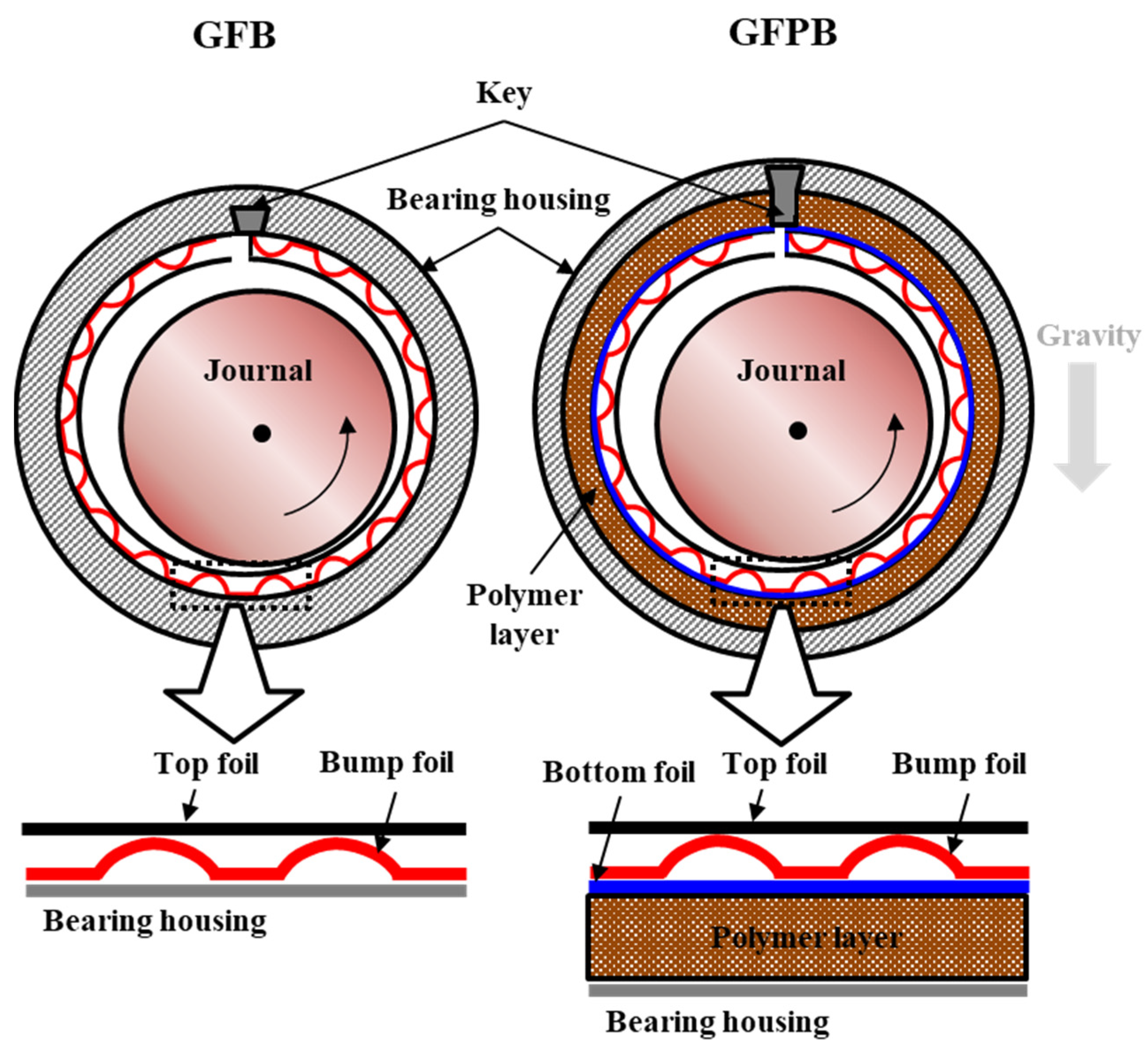
A bump-type gas foil bearing (GFB) is a type of gas bearing with an arched bearing structure. The bearing structure of the GFB consists of a bump and top foils, as shown in Figure 1. The foil structure is located between the journal and the bearing housing. The top foil has a smooth bearing surface to form a hydrodynamic pressure. The bump foil has an arched elastic structure, which improves the load-carrying capacity [3]. One end of the foil structure is spot-welded to a bearing key, which is inserted and secured into the housing keyway to hold the foil structure in place. In addition, the sliding effects between the bump foil and the top foil/bearing housing provide dry friction damping. This improves rotordynamic stability [4,5]. In addition, GFBs have the advantages of simple construction, light weight, and high-temperature operation; they are mainly applied to high-speed and light rotating machines: small turbines, motors, and generators.
On the other hand, GFBs become unstable and too sensitive usually in high speeds due to the subsynchronous instability, i.e., the oil whip and oil whirl phenomena. The oil whirl phenomenon corresponding to the 0.5× component of rotating speed and the oil whip phenomenon fixed to the natural frequency of the system are the major instabilities experienced by rotors supported by gas foil bearings [6].
One way to inhibit the instability in rotors is to apply mechanical preload to the GFB. Kim et al. [7] conducted an experimental study on the effect of mechanical preload on rotordynamic performance of GFB. Mechanical preload was applied by inserting three metal shims under the bump foil of the GFB at 120° in circumference. They demonstrated that the mechanical preload improves bearing load-carrying capacity and reduces the subsynchronous instability.
Figure 1.
Schematic view of a one-pad journal GFB and GFPB and their sub-structures [8].
Figure 1.
Schematic view of a one-pad journal GFB and GFPB and their sub-structures [8].

Another way to inhibit the instability effectively is the insertion of high-damping materials into the GFB. For example, there is a gas foil–polymer bearing (GFPB) proposed by Sim and Park [9]. The GFPB is a bearing with an additional polymer layer inserted into the existing GFB structure, which has a thickness of several millimeters. Figure 1 shows the structures of the GFPB and GFB. The polymer layer was inserted between the bottom foil and bearing housing. Technically, it provides additional hysteresis damping of rotor vibrations, which serves to reduce sudden impact or large amplitude vibrations of the rotor.
Sim and Park [9] determined that the GFPB structure has 200% to 400% higher damping properties compared to the GFB structure through structural excitation experiments. Furthermore, rotordynamic experiments with a single rotor system were conducted by applying the GFPB and GFB. They found that the GFPB could delay the occurrence of instability at the same bearing clearance by 35%. Furthermore, they established a simple structural model for GFPBs and demonstrated bearing stability performance with respect to the polymer layer thickness in [8]. The study showed the selection of the appropriate thickness of the polymer layer is required to improve structural stiffness and damping characteristics; the 3 mm thickness is the best in the study.
Lee et al. [10,11] proposed a viscoelastic foil bearing (VEFB) with viscoelastic material inserted between the top foil and bearing housing of the GFB. Two degrees of freedom excitation experiments determined that VEFB has approximately 150% load-direction direct damping compared to GFB. This demonstrated the effect of improving GFB damping properties due to the insertion of high-damping materials
Zyywica et al. [12] presented a polymer-coated bearing on the top foil of a GFB to reduce bearing friction. The thermal properties of the bearing were evaluated through driving experiments at room temperature and high temperatures (25 °C and 100 °C, respectively). As a result, stable operation was possible while maintaining rotor vibration below 0.05 mm at high temperatures. It was also confirmed that the top foil was in good wear after the test evaluation.
Schilling et al. [13] presented a nonlinear structural model of a gas polymer bearing. The viscoelastic model of the polymer used nonlinear element models, the generalized Maxwell model, and the generalized Kelvin–Voigt model. The structural model is ductile with a rotator vibration response analysis in the time domain, predicting the rotator vibration orbit.
In this study, the dynamic stability of bearings was investigated by applying GPFB to a dual rotor system, and the stability was compared with GFB to intuitively understand the results. Tests GFPB and GFB were fabricated and tested with static load deflection tests to estimate bearing clearance. The dual rotor mechanics system was analyzed through FE analysis and modal test with natural frequency and mode shape. Finally, the stability of GFPB and GFB was investigated with a dual rotor system under the same conditions, and the bearing stability aspect was comparatively analyzed in the high-speed operation area.
2. Bearing Fabrication and Characterization Tests
2.1. Fabrication of Test Bearing
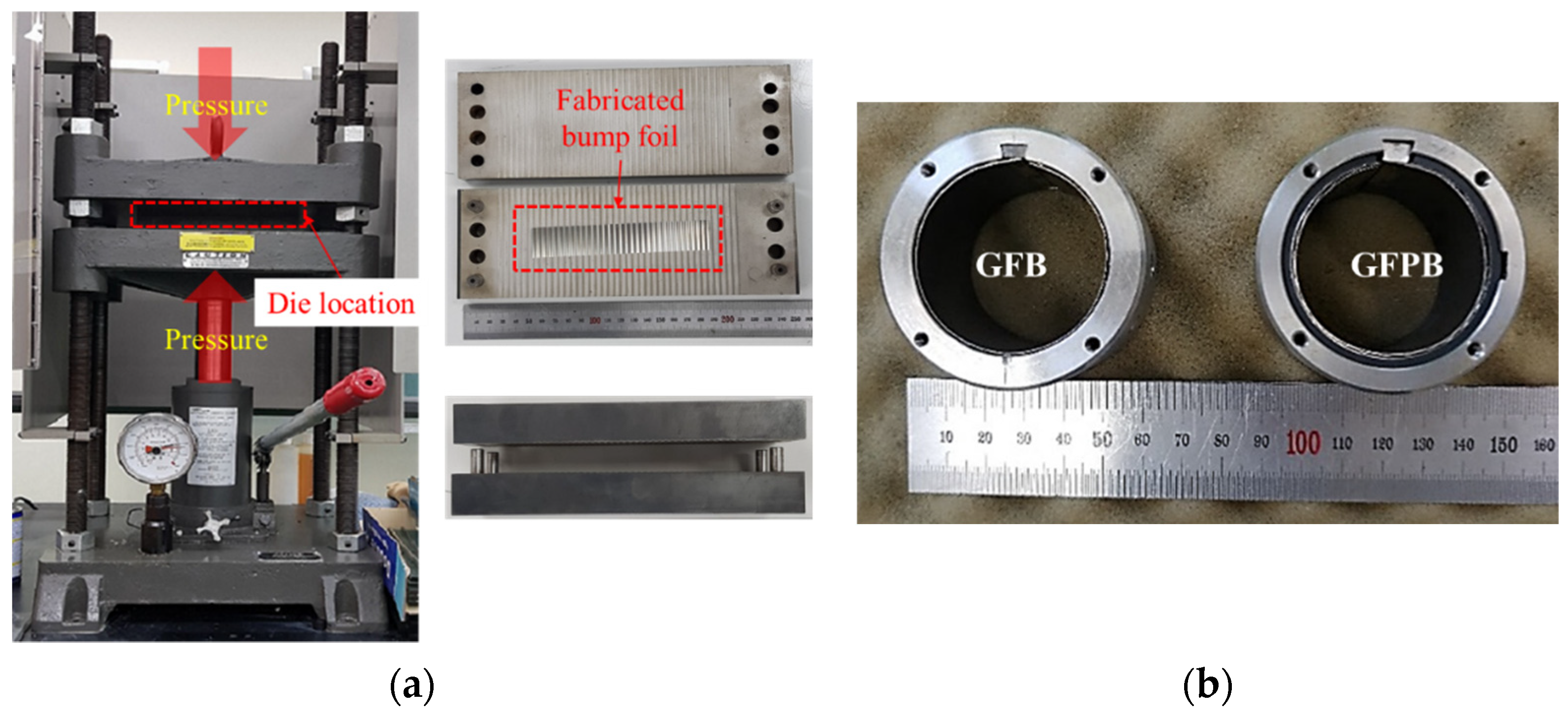
Figure 2a shows the GFPB’s bump foil fabrication process. The top/bump/bottom foil structure was made of Inconel X-750 steel plates with a thickness of 127 μm by Table 1. Inconel X-750 is suitable for bearing foil structures because of its high elastic deformation and high heat resistance with Ni–Cr alloys [14]. In addition, the top foil was coated with 20 µm thick MoS2 to reduce friction during the initial drive and stop. MoS2 has a higher load-carrying capacity and a lower friction coefficient than other solid lubricants. The bump was molded by compressing molds with bump shapes into a hydraulic press machine. The hydraulic press machine applied a load of 177 kN (approximately 18 tons) to the bump foil. This is the load under which the bump foil is perfectly molded [15].
The manufactured GFBs and GFPBs are shown in Figure 2b. The polymer layer of GFPB used a type of natural rubber, nitrile butadiene rubber (NBR). NBR is used as an o-ring and seal because of its excellent oil resistance and wear resistance. It has a stable heat resistance of −55 °C to 125 °C. NBR has better damping properties than commonly used engineering rubbers, such as natural rubber, styrene butadiene rubber, and ethylene propylene diene monomers, making it suitable for vibration reduction [16,17]. Therefore, in this work, an NBR polymer with a thickness of 2 mm and width of 35 mm was applied to the bearings.
2.2. Measurement of Clearance in Test Bearing
In general, the normal clearance of gas bearings is not clearly identified in most applications [15]. The bearing clearance of the GFB and GFPB is defined as the air gap between the journal and the foil. Bearing clearance is the most important characteristic for determining the performance of bearings. Therefore, it is important to keep the clearance constant during the test. A common way to measure the bearing clearance in GFBs and GFPBs is to use the static load–deflection test proposed by Rushitto et al. [18].
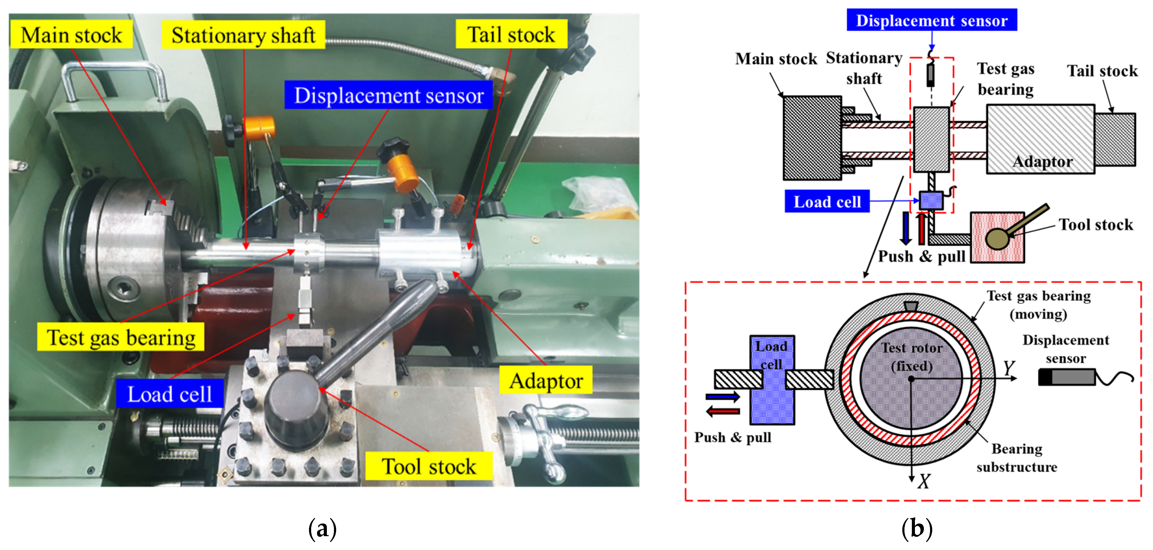
Figure 3 shows a static load–deflection test rig using a lathe. Both sides of the stationary shaft are fixed by connecting it to the main stock and tail stock. The test gas bearing mounted on the stationary shaft is connected to the load cell and tool stock and transferred in the Y-direction. If the transfer range exceeds the bearing clearance, mechanical contact between the bearing substructure and the stationary shaft occurs. At this point, the reaction force is measured in the load cell. The displacement sensor measures the transfer distance of the bearings.
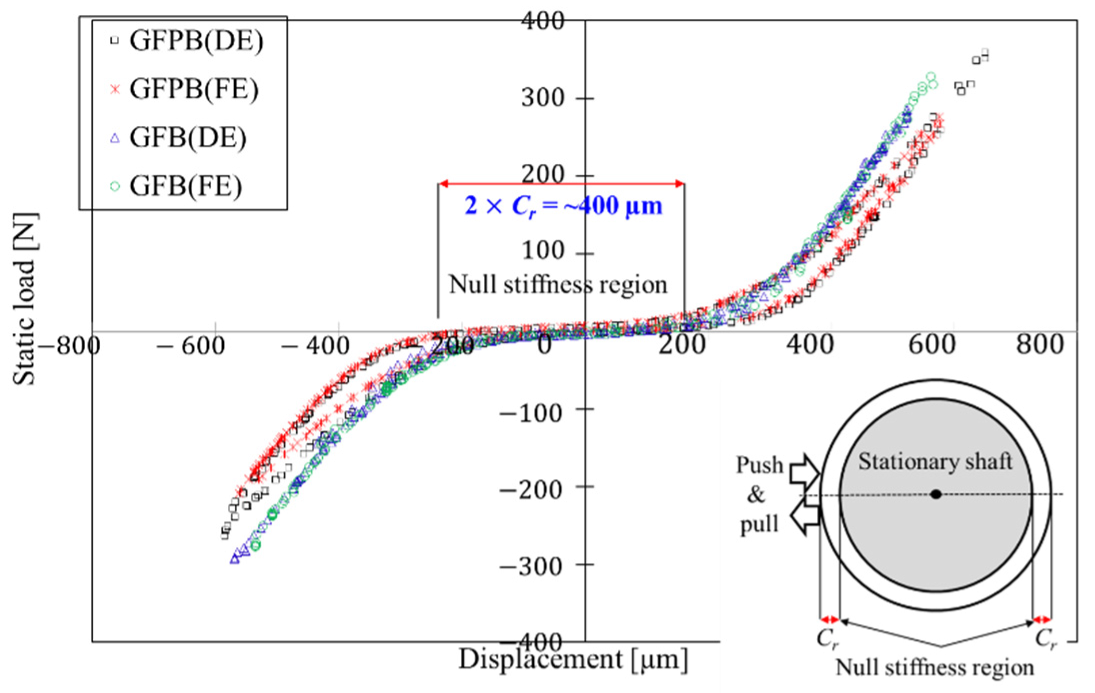
Figure 4 shows the measured static load and bearing transfer distance for the GFPB and GFB. The load–displacement curve of the structure can be analyzed as a hysteresis curve. The slope of the hysteresis curve represents the ratio of the static load to the displacement, i.e., the coefficient of stiffness. The area of the curve represents the energy dissipated by damping [19]. Therefore, the experimental results indicate that GFPB has relatively low structural stiffness and high damping compared with GFB. Note that the results of the dynamic loading tests for the same bearing structures in [9] showed that the GFPB structure has higher damping properties of 200–400% than the GFB structure, mainly due to significant hysteresis damping of the polymer layer in the GFPB.
Meanwhile, a large nonlinear behavior occurs near ±200 µm. This is judged to be nonlinear by increasing the contact area of the shaft and bearing structure as the bearing transfer distance exceeds the bearing clearance. Therefore, it can be assumed that the region before the load increases nonlinearly, i.e., the displacement region close to null stiffness region, is equal to twice the bearing clearance (=2 × Cr). As a result, the clearances of the two bearings were measured as approximately 200 µm.
3. Verification of Mode Properties of a Dual-Rotor
3.1. Dual-Rotor Rotordynamic Test Rig
Prior to the rotordynamic test, the natural frequency and mode shape properties of the dual-rotor rotodynamic test rig were considered. In the case of a single-rotor system supported by gas bearings, the first two eigenmodes occur in the rigid-body modes, the cylinder and the conical mode, so that the system is rarely dangerous due to excessive vibration. However, in the case of a dual-rotor system, since the first two eigenmodes occur as a bending mode of the coupling, excessive vibration may break the coupling and cause the rotor to disengage. Therefore, in the dual-rotor system, it is essential to understand the natural mode characteristics of the system in advance before rotordynamic tests.
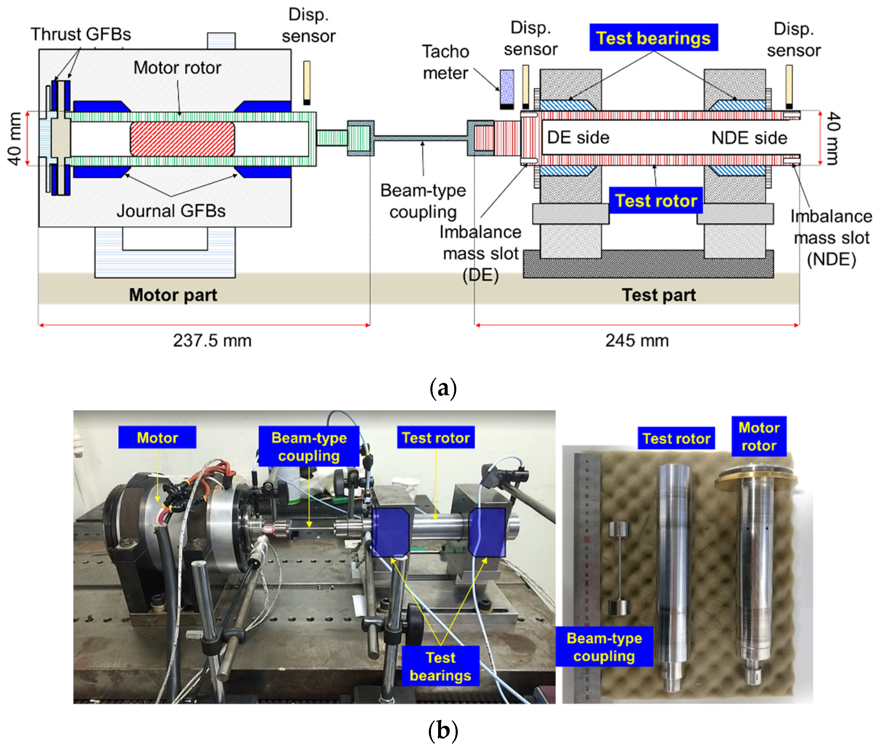
Figure 5 shows a dual-rotor rotodynamic test rig. The test rig consists of a high-speed motor and a test rotor powered by the electric motor. The motor is a 13-kW permanent-magnet type that can run up to 100 krpm [9]. The motor rotor and the test rotor are connected by a beam-type coupling for power transfer.
The motor rotor is supported by two journal GFBs, with a diameter of 40 mm, length of 237.5 mm, and mass of 2.0 kg. The detailed motor rotor dimensions and inertial information are described in [9]. The test rotor is supported by two journal GFBs or GFPBs, which can be replaced by bearings depending on the test conditions. The test rotor is made of high-temperature material, Inconel 718, in the form of a hollow shaft. Its diameter and length are 40 and 245 mm, respectively, and its mass is 1.338 kg. Information on the rotors and couplings is presented in Table 2. Meanwhile, the rotordynamic performance of the dual rotor system with controlled imbalances was evaluated in Appendix A in detail.
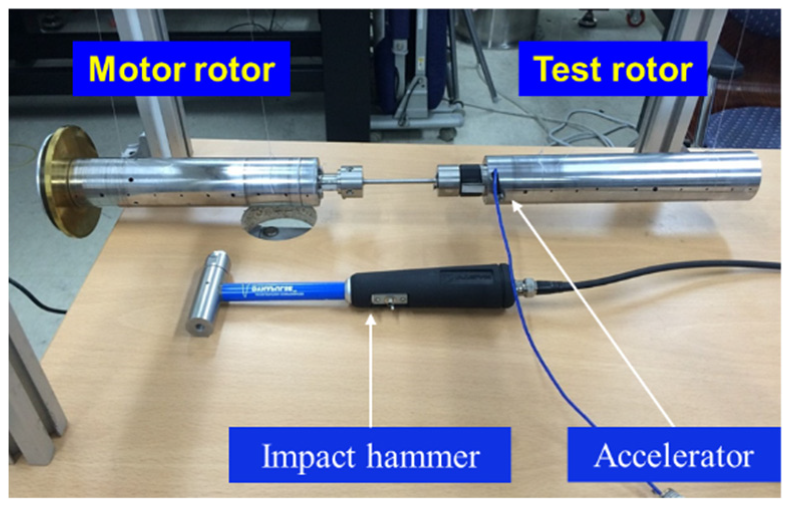
Figure 6 shows the natural frequency test environment for a dual rotor. The dual rotor was made in a free–free condition with a string. An accelerometer was attached to the drive end (DE) side of the test rotor to measure the vibration response of the rotor. The impact force applied on the rotor was measured using an impact hammer. The frequency response function was calculated at all rotor positions by repeated measurements, as the points were shifted.
3.2. Modal Test and Analysis
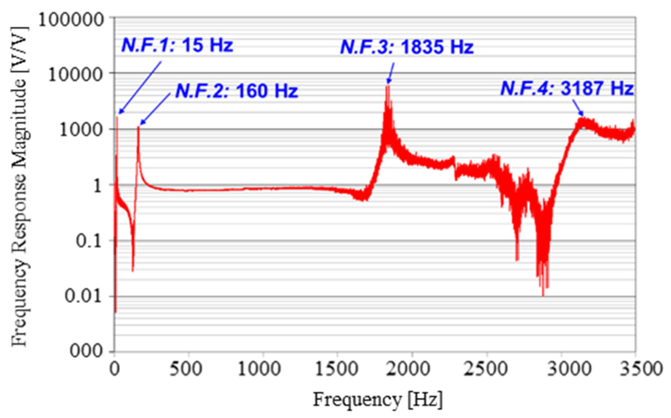
Figure 7 shows the frequency response function measured at a particular point. The frequency response function is an acceleration function corresponding to the ratio of the force and acceleration response, defined as:
where the subscript represents the impact point, and represents the response point. In the test results, the natural frequency can be determined as the peak point at which the response occurs significantly. Four natural frequencies are located within 3500 Hz, with the first-order natural frequency being 15 Hz (0.9 krpm) and the second-order natural frequency being 160 Hz (9.6 krpm). The first- and second-order natural frequencies and the third-order natural frequencies are significantly separated, with values of 1835 Hz (110 krpm).
Next, the natural frequency of the dual rotor was predicted through a three-dimensional finite element (FE) analysis in the same free–free condition as in the test. The analysis used Modal Analysis from ANSYS Workbench 16 [20], which is a three-dimensional FE analysis software. The key dimensions and material information of the motor rotor used in the analysis are described in previous reports [9,21].
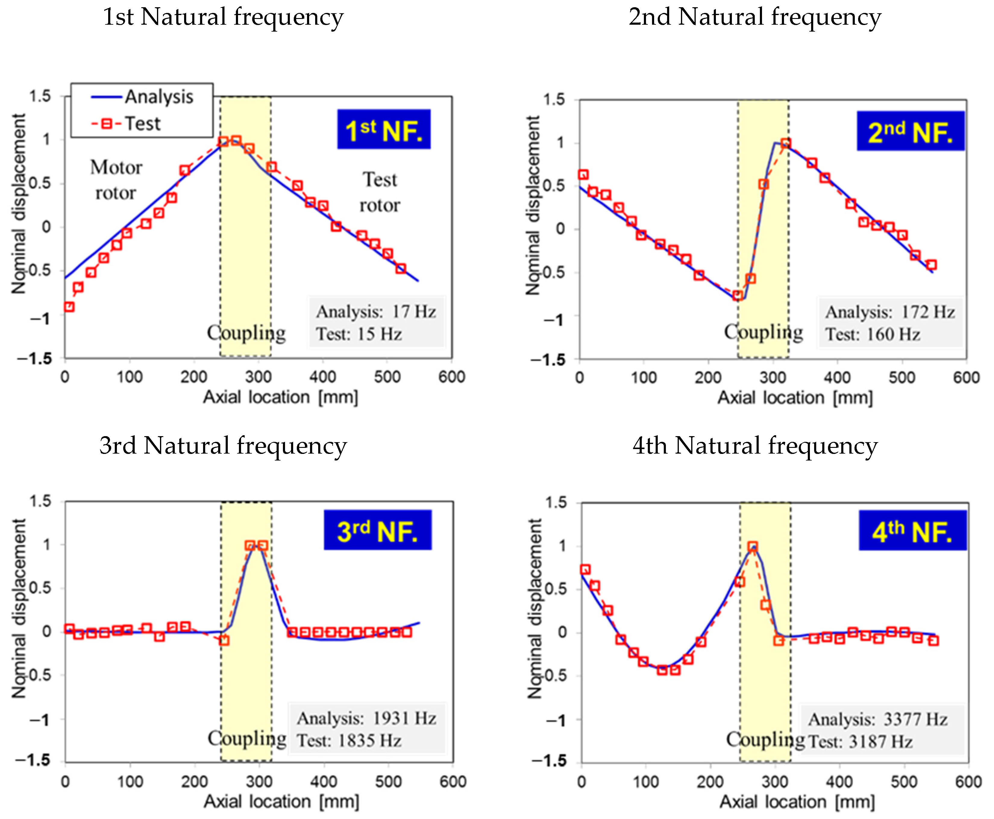
Table 3 shows the first- to fourth-order natural frequencies derived from the test and analysis, and shows the relative error. The results of the test and analysis have an error of 5–7%, indicating that the tests and analyses were reliable. Furthermore, the analysis at all orders has a larger value than that of the test, and its error is relatively constant. This is judged to be a bias error that occurs when the material properties are different from the actual ones in analysis modeling. Therefore, if the accuracy of the analysis model is calibrated through material property adjustment, it can be inferred that model can be calibrated up to an error of approximately 1%.
Figure 8 shows the mode shape at the first- to fourth-order natural frequencies derived from the test and analysis. The test and analysis results tended to be consistent across the board. In particular, in relatively low-order modes, such as first- and second-order modes, the motor and the test rotor behave rigidly, and the coupling with relatively weak stiffness deforms into a U or S shape. This is a typical dual-rotor bending mode. In addition, higher-order modes, such as third- and fourth-order modes, result in bending modes of the rotor itself, in which the test rotor and motor rotor deform into a U shape.
Based on the results of the test, in the rotordynamic test, the maximum rotational speed is limited to before the third natural frequency. This is because rotors normally supported by gas bearings cannot support stable bearings in the rotor bending mode due to the low stiffness of the bearings. Thus, with API 612 criteria, the separation margin (SM) can be calculated as follows [22]:
where AF is an amplification factor of rotor vibration. In this work, the AF is assumed to be infinitely large for a conservative approach. The SM is then calculated to be 26%, and, when it is applied to the third natural frequency, the maximum rotational speed of the dual-rotor rotodynamic test rig is approximately 92 krpm.
4. Rotordynamic Test
4.1. Test Methods
The performances of GFB and GFPB for bearing stability were compared under the same conditions using a dual-rotor rotordynamic test rig.
The test bearings were journal GFB and GFPB and were mounted in the DE and non-drive-end (NDE) positions to support the test rotor under test conditions. Because the bearing clearance of 200 µm measured as described in Section 2 is generally a large value, the bearing clearance was equally adjusted to 150 µm in the rotordynamics tests. This reduced the bearing clearance by inserting a 50-µm-thick shim between the bump foil and the bearing housing in the circumferential direction. The bearing clearance was reduced by inserting a 50-µm- thick shim between the bump foil and the bearing housing in the circumferential direction.
The measurement data measured the DE and NDE horizontal and vertical vibrations of the test rotor and the vertical vibrations of the motor rotor using five eddy-current displacement sensors. The rotational speed of the test rotor was also measured using an optic tachometer. The test method accelerated the motor and the coast down when subsynchronous instability was observed in the rotor vibration signal at high speed. In particular, the rotor vibration measured during the coast down can be seen as a pure rotordynamic vibration phenomenon without electromagnetic and noise components of the motor.
4.2. Test Result
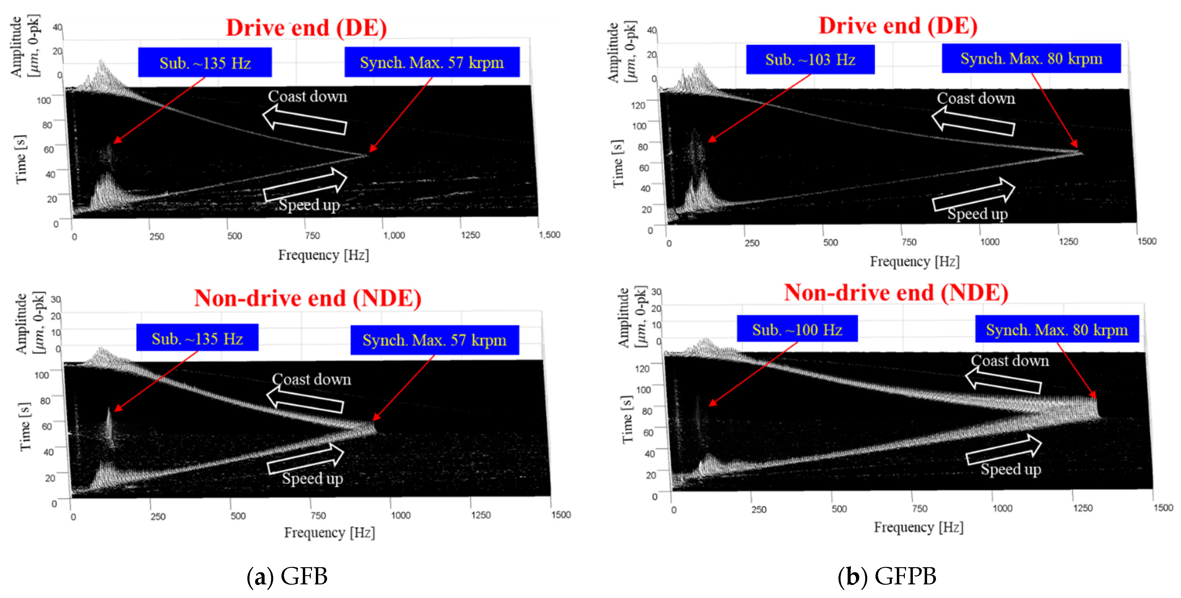
Figure 9 shows vertical rotor vibration signals measured when two bearings of the test rotor were supported by the GFB and the GFPB. Subsequently, all measured vibration signals were analyzed only in the vertical direction—the gravity direction. Both bearings showed the first harmonic synchronous components of the rotational speed, while the second harmonic components are negligible, which is known to mainly result from rotor rubbing. This means that the test GFBs and GFPBs have their bearing clearances maintained well during operations. Moreover, it can be inferred that the dual-rotor systems composed of a motor rotor-coupling-test rotor supported on four gas bearings are well aligned.
GFB has a subsynchronous instability of approximately 135-Hz components at high speeds, lasting up to a maximum rotational speed of 57 krpm. GFPB, however, has subsynchronous instability from approximately 100 to 103 Hz, lasting up to a maximum rotational speed of 80 krpm. Therefore, for both bearings, the oil whip phenomenon, in which instability is fixed at a natural frequency, is dominant. The associated natural frequency is judged to be 160 Hz, which is an S-shaped second-order mode.
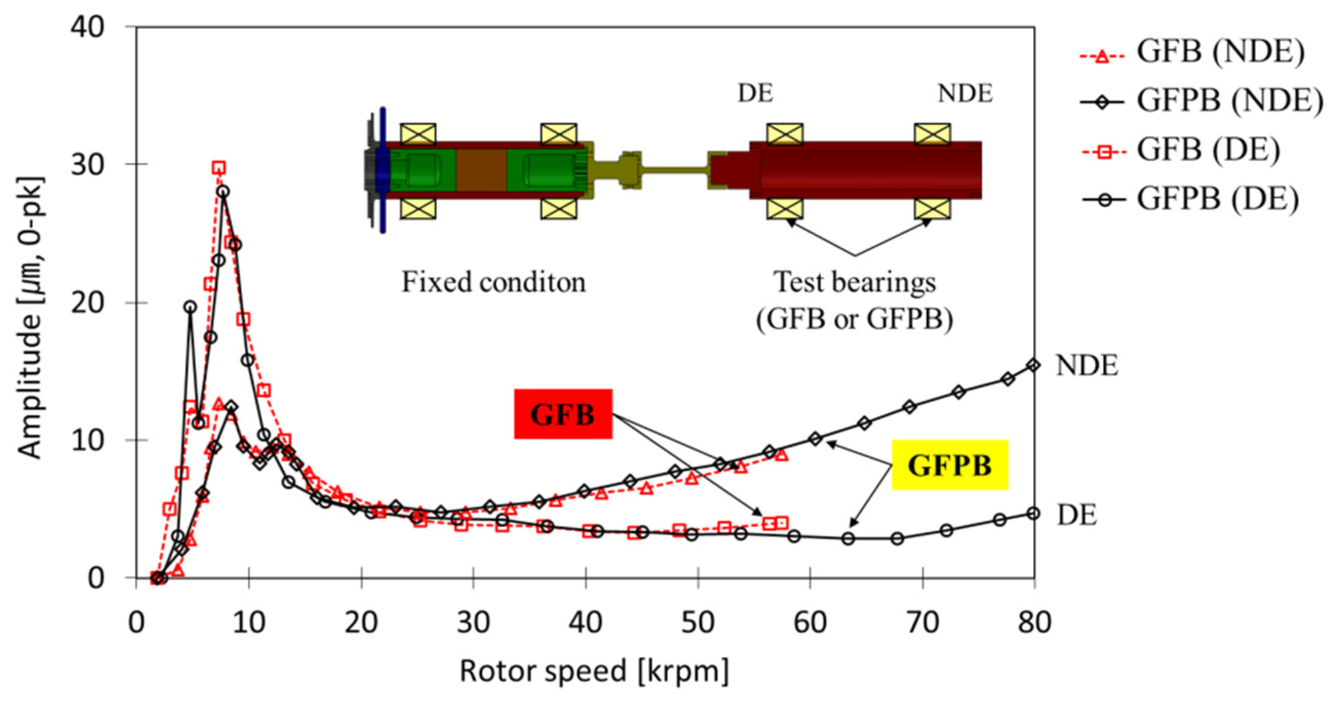
Figure 10 indicates the frequency analysis of the vibration signals measured on the DE and NDE sides, showing the amplitude of the 1× synchronous component relative to the rotational speed. The amplitude value is the magnitude of pure vibration with the runout of the rotor removed—i.e., the vibration signal measured at each rotational speed is represented by a vector, from which a runout vector is removed, resulting in the extraction of the pure rotor vibration vector. Mathematically, this can be expressed as:
where, , , and . Here, is the vibration with runout removed, is the vibration signal measured at each rotational speed, and is the runout of the rotor. The runout of the rotor is equivalent to the vibration signal of the measured displacement sensor, rotating the rotor at a low speed with no dynamic rotor vibration effect [23].
The amplitude of the synchronous component is of a similar magnitude to those of the GFB and GFPB, especially at approximately 8.5 krpm (~142 Hz), resulting in an amplitude of as much as 30 µm because of the critical speed. This is 20% of the bearing clearance of 150 µm, which is not considered to be a significant level of vibration affecting the system. It can also be inferred that the two bearings do not differ in terms of stiffness near the critical speed (~8.5 krpm). This is because the critical speed is determined by the bearing stiffness owing to the characteristics of the rotor–gas bearing system, where the rigid mode of the rotor mainly occurs [21]. However, the phenomenon of NDE vibration increasing with increasing rotational speed seems to be the effect of vibration as the rotational speed approaches the third-order mode.
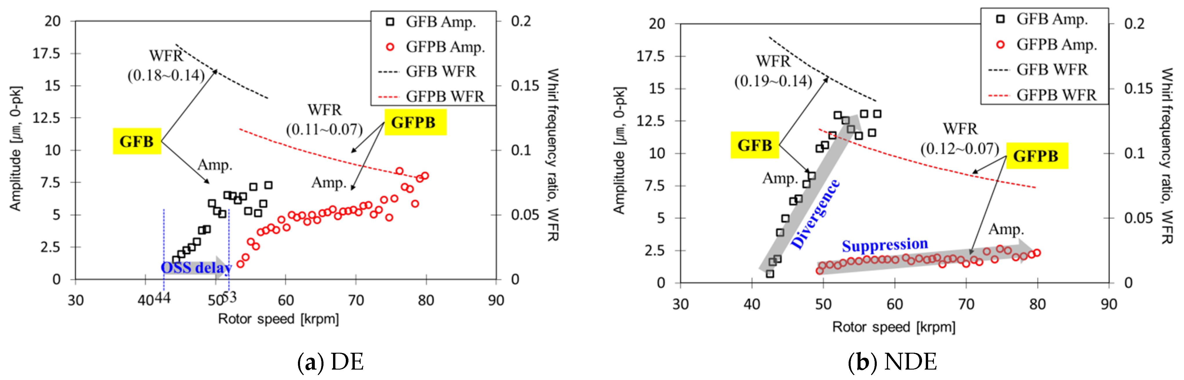
Figure 11 shows the subsynchronous amplitude and whirl frequency ratio (WFR) of the GFB and GFPB. The WFR is the ratio of the subsynchronous frequency to the rotational speed, which can be considered as a stability indicator. For example, a WFR of 0.2 means that the sub-synchronous motion occurs with the frequency of 20% of the rotational speed; stable operation without subsynchronous instability is possible up to five times the natural frequency of the system. Note that subsynchronous instability is known to be related to the oil-whip phenomenon occurs at a natural frequency of rotor-bearing system [6,24]. Therefore, a smaller WFR means a higher operating speed without subsynchronous instability given a system natural frequency.
The onset subsynchronous speed (OSS) of the GFPB is approximately 53 krpm, which is approximately 9 krpm higher than that of the GFB. Moreover, the amplitude of the GFPB at the same speed is formed lower and is more effectively suppressed in the event of instability. In particular, the instability of the GFPB in the NDE maintains a continuously low amplitude up to 80 krpm. This phenomenon is attributed to the significant improvement in the damping properties of GFPB because of the inserted polymer layer, which effectively attenuates the instability.
Meanwhile, the WFR has a GFPB range of 0.07 to 0.12 (average of 0.1) and a GFB of 0.14 to 0.19 (average of 0.17). In other words, the GFPB is approximately 10 times and the GFB is approximately 5.9 times, making stable driving possible without instability at higher rotational speeds than their natural frequencies, and the stability of the GFPB is significantly higher.
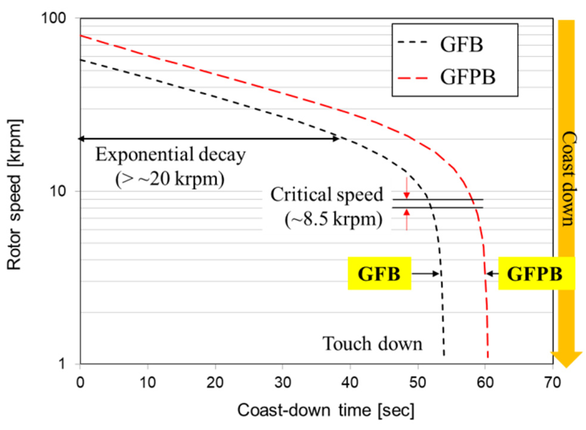
Figure 12 shows the rotational speed during coast down as a log scale. There seems to be no difference in the rotational speeds of the two bearings, namely, the friction torque. Therefore, the frictional properties of the bearings do not change significantly, even when a polymer layer is inserted. In conclusion, GFPB has the same bearing friction properties as to GFB, but it has significantly improved bearing stability, which can be used effectively to suppress instability. In addition, near the critical speed of approximately 8.5 krpm, there is a boundary friction or dry friction phenomenon in which the rotational speed decreases sharply. Therefore, owing to the large friction error near the critical speed, accurate bearing performance comparisons from Figure 9, Figure 10 and Figure 11 are difficult.
5. Conclusions
In this study, bearing stability was investigated experimentally by applying a GFPB with a high-damping polymer layer inserted into a biaxial rotor system with a diameter of 40 mm and a total length of 550 mm. The results were compared with those of the GFB.
The polymer layer of the test GFPB used NBR, a type of natural rubber with excellent damping properties at temperatures ranging from −55 °C to 125 °C. The polymer layer was 2 mm thick and 35 mm wide. The manufactured GFPB and GFB were measured for bearing clearance through a static load–deflection test, and both bearings had the same clearance of 200 µm.
As a result of the dual-rotor modal test, the first- and second-order natural frequencies were measured at 15 and 160 Hz, respectively, and the third-order natural frequency was 1835 Hz in the bending mode of the test rotor. Therefore, a separation margin of 26% was applied to the third-order natural frequency, limiting the maximum rotational speed of the dual-rotor rotordynamic test rig to 92 krpm.
The GFPB and GFB were applied to the test rotor by adjusting the bearing clearance to 150 µm using a shim. The GFPB instability began at 53 krpm and was stably suppressed to 80 krpm at an amplitude of approximately 10 µm. However, the instability of the GFB tends to start at 44 krpm and has an amplitude of approximately 13 µm at 57 krpm. This appears to be a feature of the GFPB with improved structural damping, i.e., the GFPB does not differ significantly in OSS compared with the GFB, but it is quite stable in the development of instability, especially on the NDE side.
Consequently, summarizing the results of rotordynamic experiments for synchronous and subsynchronous motions and bearing frictions in this study, GFPBs have a great advantage in terms of stability compared to the widely used GFBs. Based on these results, the authors of this study carefully recommend the use of GFPB as a lubricating element for environments where rotordynamics is unstable or where the system is subjected to shocks or periodic disturbances. Of course, the temperature conditions of the operating environment must be suitable for the use of polymers.
Author Contributions
Conceptualization, K.S.; methodology, K.S.; software, J.P.; validation, J.P. and D.K.; formal analysis, J.P.; writing—original draft preparation, J.P. and D.K.; writing—review and editing, K.S.; supervision, K.S. All authors have read and agreed to the published version of the manuscript.
Funding
This study was supported by the research program funded by SeoulTech (Seoul National University of Science and Technology).
Institutional Review Board Statement
Not applicable.
Informed Consent Statement
Not applicable.
Data Availability Statement
Not applicable.
Conflicts of Interest
The authors declare no conflict of interest.
Appendix A
In this chapter, rotordynamic performance of a dual-rotor rotordynamic test rig were evaluated with various imbalance conditions. A typical the rotor vibration by an imbalance mass () is defined as follows:
where represents the imbalance mass and represents the imbalance location radius, represents the fraction of the rotor weight action on each bearing, i.e., the rotor vibration is proportional to the imbalance mass.
Table A1 shows how to add an imbalance mass to the test rotor. Imbalance mass locations were added to the DE and NDE sides of the test rotor, and the two planes were added as in-phase and out-of-phase. Imbalanced mass sizes were 65, 140, and 215 mg.
Table A1 shows how to add an unbalanced mass to the test rotor.

Table A1.
Imbalance mass parameters of the test rotor.
| Imbalance Layout | ||
|---|---|---|
| DE | NDE | |
| In–phase | 65 mg (0°) | 65 mg (0°) |
| 140 mg (0°) | 140 mg (0°) | |
| 215 mg (0°) | 215 mg (0°) | |
| Out–of–phase | 65 mg (0°) | 65 mg (180°) |
| 140 mg (0°) | 140 mg (180°) | |
| 215 mg (0°) | 215 mg (180°) | |
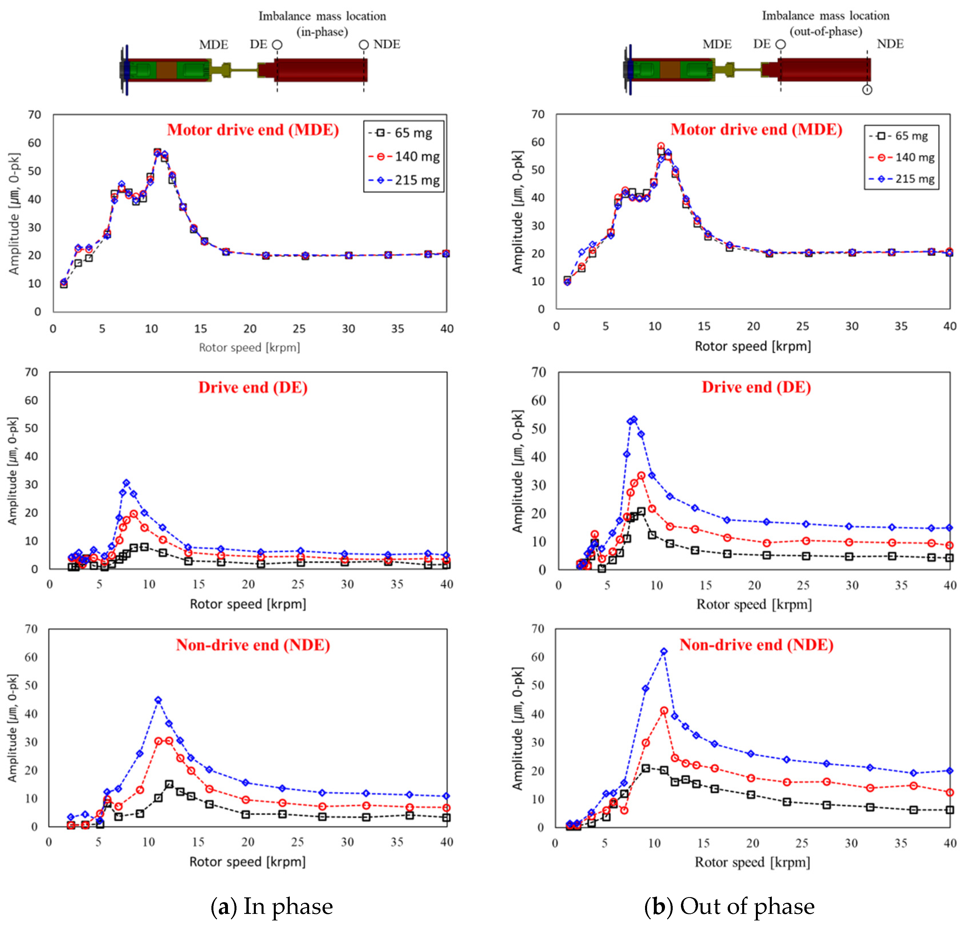
Figure A1 shows the results of a rotordynamic test with imbalance mass. The vibration of the motor rotor on the MDE side, the test rotor on the NDE side, and the DE side were measured. The vibration on the MDE side caused the same behavior, regardless of the imbalance mass. This indicates that the motor rotor and test rotor vibrations are decoupled due to the low stiffness of the beam type coupling. Vibrations on the NDE and DE sides increased proportionally as the imbalance mass increased. This is the rotordynamic performance by the general imbalance mass, as shown in Equation (A1).
On the other hand, Vibrations on the NDE and DE sides had greater levels of out of phase than in phase. This is shown to be due to the occurrence of a cylindrical mode when the imbalance mass is in phase, and a conical mode when the imbalance mass is out of phase. Therefore, this dual-rotor rotordynamic test rig demonstrates stable rotor dynamic performance. In particular, it can be seen that the decoupled effect of the motor rotor and test rotor is excellent for analyzing the rotordynamic performance of the test rotor according to bearing changes.
Figure A1.
Filtered synchronous vertical motions measured at MDE and DE, NDE sides for (a) in phase and (b) out of phase imbalance mass.
Figure A1.
Filtered synchronous vertical motions measured at MDE and DE, NDE sides for (a) in phase and (b) out of phase imbalance mass.

References
- Andrés, L.S.; Kim, T.H. Analysis of gas foil bearings integrating FE top foil models. Tribol. Int. 2009, 42, 111–120. [Google Scholar] [CrossRef]
- Kim, T.H.; Andrés, L.S. Heavily Loaded Gas Foil Bearings: A Model Anchored to Test Data. ASME J. Eng. Gas Turbines Power 2008, 130, 012504. [Google Scholar] [CrossRef]
- Heshmat, H.; Walowit, J.A.; Pinkus, O. Analysis of Gas-Lubricated Foil Journal Bearings. J. Lubr. Technol. 1983, 105, 647–655. [Google Scholar] [CrossRef]
- Simek, J. Application of a New Type of Aerodynamic Tilting Pad Journal Bearing in Power Gyroscope. Eng. Mech. 2012, 19, 359–368. [Google Scholar]
- Arora, V.; Van Der Hoogt, P.J.M.; Aarts, R.G.K.M.; De Boer, A. Identification of stiffness and damping characteristics of axial air-foil bearings. Int. J. Mech. Mater. 2011, 7, 231–243. [Google Scholar] [CrossRef] [Green Version]
- Childs, D. Turbomachinery Rotordynamics; Chapter 3; Wiley: New York, NY, USA, 1993. [Google Scholar]
- Kim, T.H.; Andrés, L.S. Effects of a Mechanical Preload on the Dynamic Force Response of Gas Foil Bearings: Measurements and Model Predictions. Tribol. Trans. 2009, 52, 569–580. [Google Scholar] [CrossRef]
- Park, J.S.; Sim, K.H. Rotordynamic Analysis of Gas Foil-Polymer Bearings Based on a Structural Elasticity Model of Polymer Layer along with Static-Load Deflection Tests. Appl. Sci. 2021, 11, 1789. [Google Scholar] [CrossRef]
- Sim, K.H.; Park, J.S. Performance measurements of gas bearings with high damping structures of polymer and bump foil via electric motor driving tests and one degree-of-freedom shaker dynamic loading tests. J. Eng. Gas Turbines Power 2017, 139, 092504. [Google Scholar] [CrossRef]
- Lee, Y.B. Dynamic characteristics of a flexible rotor system supported by a viscoelastic foil bearing (VEFB). Tribol. Int. 2004, 37, 679–687. [Google Scholar] [CrossRef]
- Lee, Y.B. Unbalance Response of a Super-Critical Rotor Supported by Foil Bearings—Comparison with Test Results©. Tribol. Trans. 2004, 47, 54–60. [Google Scholar] [CrossRef]
- Żywica, G.; Baginski, P.; Andrearczyk, A. Experimental research on gas foil bearings with polymer coating at an elevated temperature. Tribologia 2016, 3, 217–227. [Google Scholar] [CrossRef]
- Schilling, G.; Baurlein, K.; Liebich, R. Numerical Description of a Rotor Supported by Gas Polymer Bearings for Time Domain Simulations-Implementation and Parametrization of the Struc-ture Model. In Proceedings of the 13th SIRM: The 13th International Conference on Dynamics of Rotating Machinery, Copenhagen, Denmark, 13–15 February 2019; pp. 340–349. [Google Scholar]
- Radil, K.; Howard, S.; Dykas, B. The role of radial clearance on the performance of foil air bearings. Tribol. Trans. 2002, 45, 485–490. [Google Scholar] [CrossRef] [Green Version]
- Andres, L.S.; Rubio, D.; Kim, T.H. Rotordynamic performance of a rotor supported on bump type foil gas bearings: Experiments and predictions. J. Eng. Gas Turbines Power. 2007, 41, 850–857. [Google Scholar] [CrossRef]
- Song, M. Study on the Dynamic Properties of Nitrile-Butadiene Rubber/Hindered Phenol Mixtures by Molecular Dynamics Simulation. Asian J. Chem. 2013, 25, 5200. [Google Scholar] [CrossRef]
- Hwang, W.G.; Wei, K.H.; Wu, C.M. Mechanical, thermal, and barrier properties of NBR/organosilicate nanocomposites. Polym. Eng. Sci. 2004, 44, 2117–2124. [Google Scholar] [CrossRef]
- Ruscitto, D.; Mc Cormick, J.; Gray, S. Hydrodynamic Air Lubricated Compliant Surface Bearing for an Automotive Gas Turbine Engine I-Journal Bearing Performance; NASA CR-135368; Mechanical Technology Inc.: New York, NY, USA, 1978. [Google Scholar]
- Sim, K.H.; Park, J.S.; Lee, S.H. Identification of Frequency-Dependent Dynamic Characteristics of a Bump Structure for Gas-Foil Bearings via 1-DOF Shaker Tests Under Air Pressurization. Trans. Korean Soc. Mech. Eng. A 2015, 39, 1029–1037. [Google Scholar] [CrossRef]
- 2020 ANSYS. Available online: https://www.ansys.com/ (accessed on 9 September 2021).
- Park, J.S.; Sim, K.H. A feasibility study of controllable gas foil bearings with piezoelectric materials via rotordynamic model predictions. J. Eng. Gas Turbines Power 2019, 141, 021027. [Google Scholar] [CrossRef]
- Standard, A.P.I. Special Purpose Steam Turbines for Petroleum, Chemical, and Gas Industry Service; American Petroleum Institute: Washington, DC, USA, 1995. [Google Scholar]
- Flack, R.D.; Rooke, J.H.; Bielk, J.R.; Gunter, E.J. Comparison of the unbalance responses of Jeffcott rotors with shaft bow and shaft runout. J. Mech. Des. 1982, 104, 318–328. [Google Scholar] [CrossRef]
- Genta, G. Dynamics of Rotating Systems; Chapter 8; Springer: New York, NY, USA, 2005. [Google Scholar]
Figure 2.
Photos of bearing fabrication process: (a) a hydraulic press for bump foil forming, and (b) fabricated test GFB and GFPB.
Figure 2.
Photos of bearing fabrication process: (a) a hydraulic press for bump foil forming, and (b) fabricated test GFB and GFPB.

Figure 3.
Static load–deflection test setup: (a) photograph of test environment, and (b) schematic view of the test.
Figure 3.
Static load–deflection test setup: (a) photograph of test environment, and (b) schematic view of the test.

Figure 4.
Measured static load versus displacement during consecutive static loading–unloading process for GFB and GFPB.
Figure 4.
Measured static load versus displacement during consecutive static loading–unloading process for GFB and GFPB.

Figure 5.
Dual-rotor rotordynamic test rig: (a) schematic view of the test rig and sensor locations, and (b) photographs of the test rig, rotors, and a coupling.
Figure 5.
Dual-rotor rotordynamic test rig: (a) schematic view of the test rig and sensor locations, and (b) photographs of the test rig, rotors, and a coupling.

Figure 6.
Overall configuration of natural mode characteristic test environment.

Figure 7.
Measured frequency response function of a dual-rotor.

Figure 8.
Measured and predicted mode shapes of a dual rotor for first through fourth order.

Figure 9.
Waterfall plots of measured vertical motions during the speed-up and coast-down process.

Figure 10.
Filtered synchronous vertical motions measured at DE and NDE sides for GFB and GFPB.

Figure 11.
Filtered sub-synchronous vertical motions for GFB and GFPB: measured at (a) DE and (b) NDE sides.
Figure 11.
Filtered sub-synchronous vertical motions for GFB and GFPB: measured at (a) DE and (b) NDE sides.

Figure 12.
Measured rotor speed versus time during the coast-down process for GFB and GFPB.

Table 1.
Test bearing design parameters.
| Part | Parameters | Values |
|---|---|---|
| Test bearings | Length | 35.00 mm |
| Geometric clearance (designed) | 0.20 mm | |
| Geometric clearance (adjusted for tests) | 0.15 mm | |
| Bump foil | Thickness | 0.13 mm |
| Bump height | 0.50 mm | |
| Bump pitch | 4.57 mm | |
| Bump half length | 1.81 mm | |
| Material | Inconel X-750 | |
| Polymer layer | Thickness | 2.00 mm |
| Width | 35.00 mm | |
| Material | Nitrile Butadiene rubber |
Table 2.
Design parameters of the dual-rotor rotordynamic test rig.
| Part | Parameters | Values |
|---|---|---|
| Test rotor | Diameter | 40.00 mm |
| Length | 245 mm | |
| Mass | 1.338 kg | |
| Material | Inconel718 | |
| Moment of inertia (polar, transverse) | 0.35 g-m2, 6.39 g-m2 | |
| Motor rotor | Diameter | 40.00 mm |
| Length | 237.5 mm | |
| Mass | 2.0 kg | |
| Coupling | Beam diameter | 3.00 mm |
| Beam length | 70.00 mm | |
| Mass | 38.7 × 10-³ kg | |
| Moment of inertia (polar, transverse) | 4.45 × 10⁻³ g-m2, 6.82 × 10⁻² g-m2 | |
| Material | Titanium alloy | |
| Lateral stiffness | 1.47 × 10⁻⁴ N/m | |
| Test bearings | Geometric clearance | 150 µm (adjusted with shim) |
Table 3.
Comparison between experimental and analysis results for natural frequencies of a dual rotor.
Table 3.
Comparison between experimental and analysis results for natural frequencies of a dual rotor.
| Order | Experiment (Hz) | Analysis (Hz) | Relative Error (%) |
|---|---|---|---|
| 1st | 15 | 17 | 6 |
| 2nd | 160 | 172 | 7 |
| 3rd | 1835 | 1931 | 5 |
| 4th | 3187 | 3377 | 6 |
Publisher’s Note: MDPI stays neutral with regard to jurisdictional claims in published maps and institutional affiliations. |
© 2022 by the authors. Licensee MDPI, Basel, Switzerland. This article is an open access article distributed under the terms and conditions of the Creative Commons Attribution (CC BY) license (https://creativecommons.org/licenses/by/4.0/).
Share and Cite
MDPI and ACS Style
Park, J.; Kim, D.; Sim, K. Development and Performance Measurements of Gas Foil Polymer Bearings with a Dual-Rotor Test Rig Driven by Permanent Magnet Electric Motor. Appl. Sci. 2022, 12, 1505. https://doi.org/10.3390/app12031505
AMA Style
Park J, Kim D, Sim K. Development and Performance Measurements of Gas Foil Polymer Bearings with a Dual-Rotor Test Rig Driven by Permanent Magnet Electric Motor. Applied Sciences. 2022; 12(3):1505. https://doi.org/10.3390/app12031505
Chicago/Turabian StylePark, Jisu, Donghee Kim, and Kyuho Sim. 2022. "Development and Performance Measurements of Gas Foil Polymer Bearings with a Dual-Rotor Test Rig Driven by Permanent Magnet Electric Motor" Applied Sciences 12, no. 3: 1505. https://doi.org/10.3390/app12031505
Note that from the first issue of 2016, this journal uses article numbers instead of page numbers. See further details here.