Article

Circuit Breakers in Low- and Medium-Voltage DC Microgrids for Protection against Short-Circuit Electrical Faults: Evolution and Future Challenges

by
Bayron Perea-Mena
,
Jaime A. Valencia-Velasquez
,
Jesús M. López-Lezama
*,
Juan B. Cano-Quintero
and
Nicolás Muñoz-Galeano
Research Group on Efficient Energy Management (GIMEL), Departamento de Ingeniería Eléctrica, Universidad de Antioquia (UdeA), Calle 70 No. 52-21, Medellin 050010, Colombia
*
Author to whom correspondence should be addressed.
Appl. Sci. 2022, 12(1), 15; https://doi.org/10.3390/app12010015
Submission received: 4 October 2021 / Revised: 3 December 2021 / Accepted: 16 December 2021 / Published: 21 December 2021

Abstract

:
This paper deals with circuit breakers (CBs) used in direct current microgrids (DCMGs) for protection against electrical faults, focusing on their evolution and future challenges in low voltage (<1.5 kV) and medium voltage (between 1.5 kV and 20 kV). In recent years, proposals for new circuit-breaker features have grown. Therefore, a review on the evolution of circuit breakers for DCMGs is of utmost importance. In general terms, this paper presents a review concerning the evolution of circuit breakers used in DCMGs, focusing on fuses, mechanical circuit breakers (MCBs), solid-state circuit breakers (SSCBs), and hybrid circuit breakers (HCBs). Their evolution is presented highlighting the advantages and disadvantages of each device. It was found that although modern circuit breakers have begun to be commercially available, many of them are still under development; consequently, some traditional fuses and MCBs are still common in DCMGs, but under certain restrictions or limitations. Future challenges that would allow a successful and adequate implementation of circuit breakers in DCMGs are also presented.

1. Introduction

Topics related to DCMGs have achieved popularity in recent years, due to the advantages that these present compared to their counterparts, the so-called alternating current microgrids (ACMGs). Some of the advantages of DCMGs include higher efficiency, greater expandability, greater stability, easier control, greater reliability, greater compatibility with renewable energy sources, and fewer conversion steps [1,2,3]. However, implementation of DCMGs involves new technical challenges to reach their full potential; among them, the implementation of a suitable protection of the system [4,5]. Moreover, it has been highlighted that there are currently no standards or guidelines for DCMG implementation [6,7,8,9,10,11].
DCMGs are projected as the stage for modern distribution systems due to the proliferation of distributed generation (DG) [12,13]. DCMGs can be defined as a group of loads and DC sources that function as a single controllable system, providing energy to its local and clearly defined area [2,13]. DCMGs are composed of sources that are driven by power electronics devices. These devices, under certain operative conditions, may handle currents between two and three times the nominal current for at least tens of microseconds [14,15], while conventional AC sources can sustain a fault current greater than 20 times their nominal current for hundreds of milliseconds [16]; in consequence, the protective devices used for ACMGs do not fulfill the minimal requirements for DCMGs. The proliferation of DCMGs is an important step in making the future power system load-adaptive, an important requirement for DG. Nonetheless, conventional MCBs for DC protection struggle to extinguish the arc generated when interrupting the fault current, and they also feature relatively slow tripping times, which represents a potential risk for sources and loads [5,7].
The design criteria for electrical fault-protection circuit breakers in DCMGs must consider the following characteristics: low power loss, reliability, speed, continuity, economy, and simplicity [1,8,17]. Regarding microgrid protection, three aspects are addressed: protective circuit-breaker circuits, protection system design, grounding and ground fault isolation [7]. Regarding microgrid fault protection circuits, the most common protections are fuses, MCBs, SSCBs, and HCBs [7]. Circuit breakers’ evolution for DCMGs has basically consisted of fuses, MCBs, SSCBs, and HCBs.
Fuses are divided into two types: fast-acting fuses and time-delay fuses. Fast-acting fuses are used to protect the output of converters and are widely used in stationary battery protection [18,19]. Time-delay fuses are used for high-frequency current peaks that occur when energizing certain loads or when starting motors. The selection of a fuse for an ACMG requires a response time between 10–100 ms to correctly operate and interrupt the fault; however, DCMGs require a maximum of 0.5 ms [18]. Although the fuse is an inexpensive protection device with very simple construction characteristics, it has the disadvantage of having to be replaced after each fault, and does not have the possibility of discriminating between a transient or a permanent fault.
MCBs are devices that use mechanical parts to interrupt the flow of current in the event of a fault. The current interruption process is always accompanied by an electric arc at the moment of interruption. To mitigate the impact of the arc, passive and active current circuits have been proposed, in which a resonant LC series circuit is used for creating a zero-crossing that extinguishes the arc [20]. The main advantages of mechanical switches consist of having low losses and low investment costs; however, the fault clearance time is between 30 and 100 ms, which is too high for DCMG requirements.
SSCBs constitute an alternative to MCBs, since they do not have mechanical moving parts to operate. Additionally, the operation of SSCBs is performed by semiconductor devices. In general terms, SSCBs have the following characteristics: fast operation, arc-free, soundless, long operation useful life, and reliability. SSCBs are used for a variety of applications [16]. Different types of silicon semiconductor devices are used for the SSCB gate-turn-off thyristor (GTO), the silicon insulated-gate bipolar transistor (IGBT), integrated gate-commutated thyristor (IGCT), and cathode metal oxide semiconductor controlled thyristor (CS-MCT), each having its advantages and disadvantages. The main characteristic of these switches is their speed, with operating times lower than 100 μ s; however, SSCBs present high-power losses, and are expensive and also too large for some applications, since they require heat sinks [21]. Another group of SSCBs is devices in which the predominant material is a wide band gap (WBG), such as silicon carbide (SiC) JFETs, SiC metal-oxide-semiconductor field-effect transistors MOSFETs, SiC static induction transistors (SiC) SITs, gallium nitride (GaN) high electron mobility transistors (HEMTs), and gallium nitride (GaN) FETs. WBG semiconductors exhibit superior material properties than those based on silicon, which enables the operation of these power devices at higher-temperature operation, higher blocking voltage capabilities, and higher switching frequencies; however, WBG technology itself is still evolving towards its maturity [22].
HCBs are a combination of the best features of mechanical and solid-state switches in a single device, overcoming their corresponding drawbacks. Indeed, hybrid switches feature small conduction losses, very short operating times, long service life, and high reliability, and do not require special cooling equipment, which shows a new direction in the research and development of switches for engineering applications [16]. However, the switching speed strongly depends on the mechanical parts of the system [23].
After an exhaustive bibliography search, it was found that papers regarding DCMG protection do not focus on the evolution of circuit breakers and its future challenges. In the Ref. [9], an overview on DCMG protections scheme was presented. In the Refs. [5,21,24,25,26,27,28,29], topics such as topologies, strategies, and protection schemes were covered. In the Refs. [30,31], protections in DCMGs were described, comparing them with their ACMGs counterparts. In the Ref. [32], DC protection schemes were presented, focusing on mathematically derived metrology requirements. In the Ref. [33], benefits and shortfalls of WBG SSCBs and their applications in photovoltaic panel (PV) generators were presented. The authors in the Ref. [34] presented a comprehensive classification of the characteristics of solid-state circuit breakers in which future challenges are addressed; nonetheless, CS-MCT SSCB features are not considered, which is a strong candidate for DCMG protection [35].
The evolution and future challenges of circuit breakers for the protection of DCMGs were the main motivating factors behind this work. We provide a review of the circuit breakers used or potential candidates for DCMG protections that have been recently reported in the specialized literature. The reviewed literature covers low-voltage (<1.5 kV) and medium-voltage (between 1.5 kV and 20 kV) DCMGs [36,37]. This paper is structured as follows: Section 2 describes the DC Microgrid faults. Section 3 includes the types of DC circuit breakers used in DCMGs, namely, fuses, MCBs, SSCBs, and HCBs. Section 4 describes the evolution of DC CBs. Section 5 presents a summary of future challenges for CBs. Section 6 concludes and highlights the most important aspects of the paper.

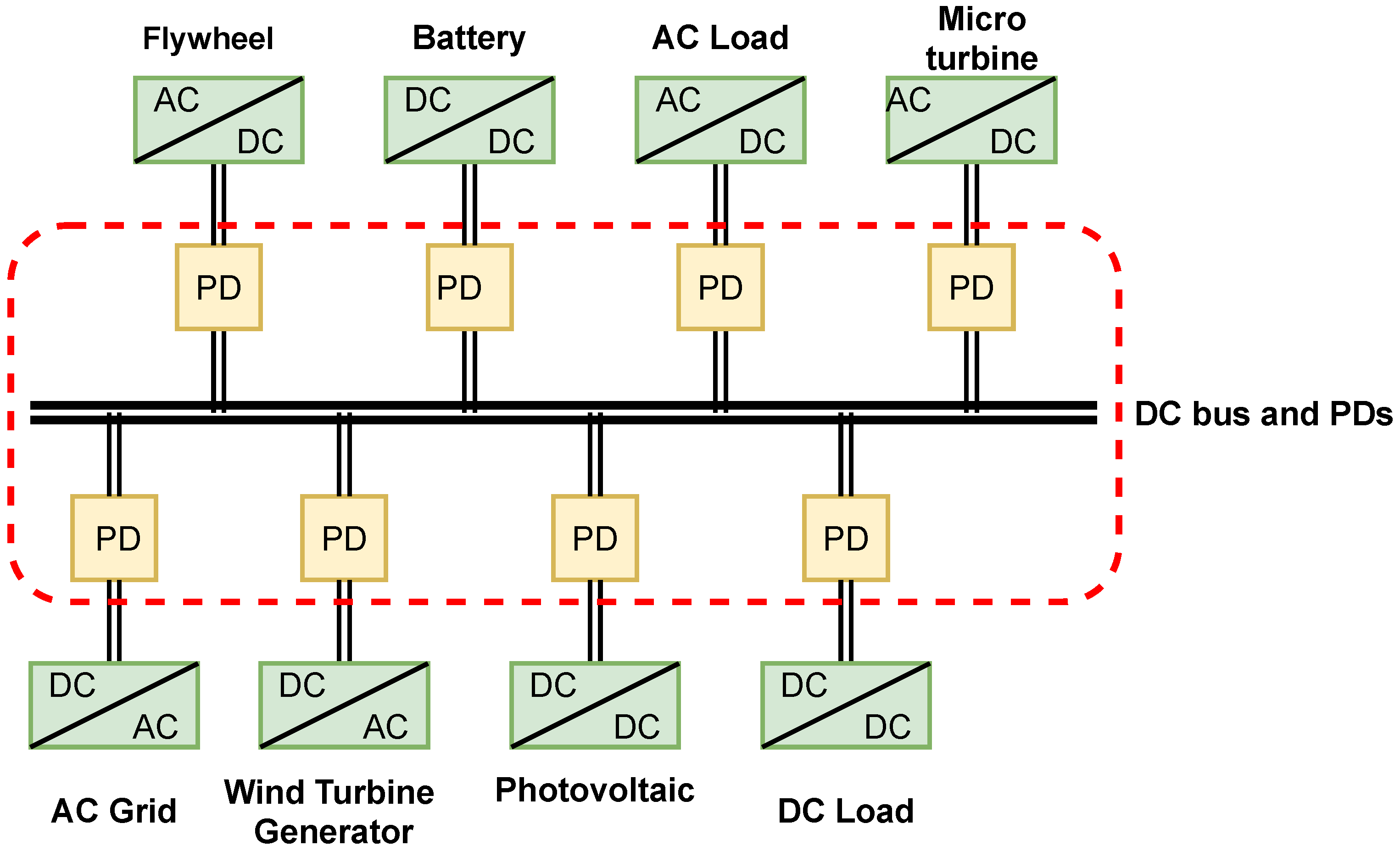
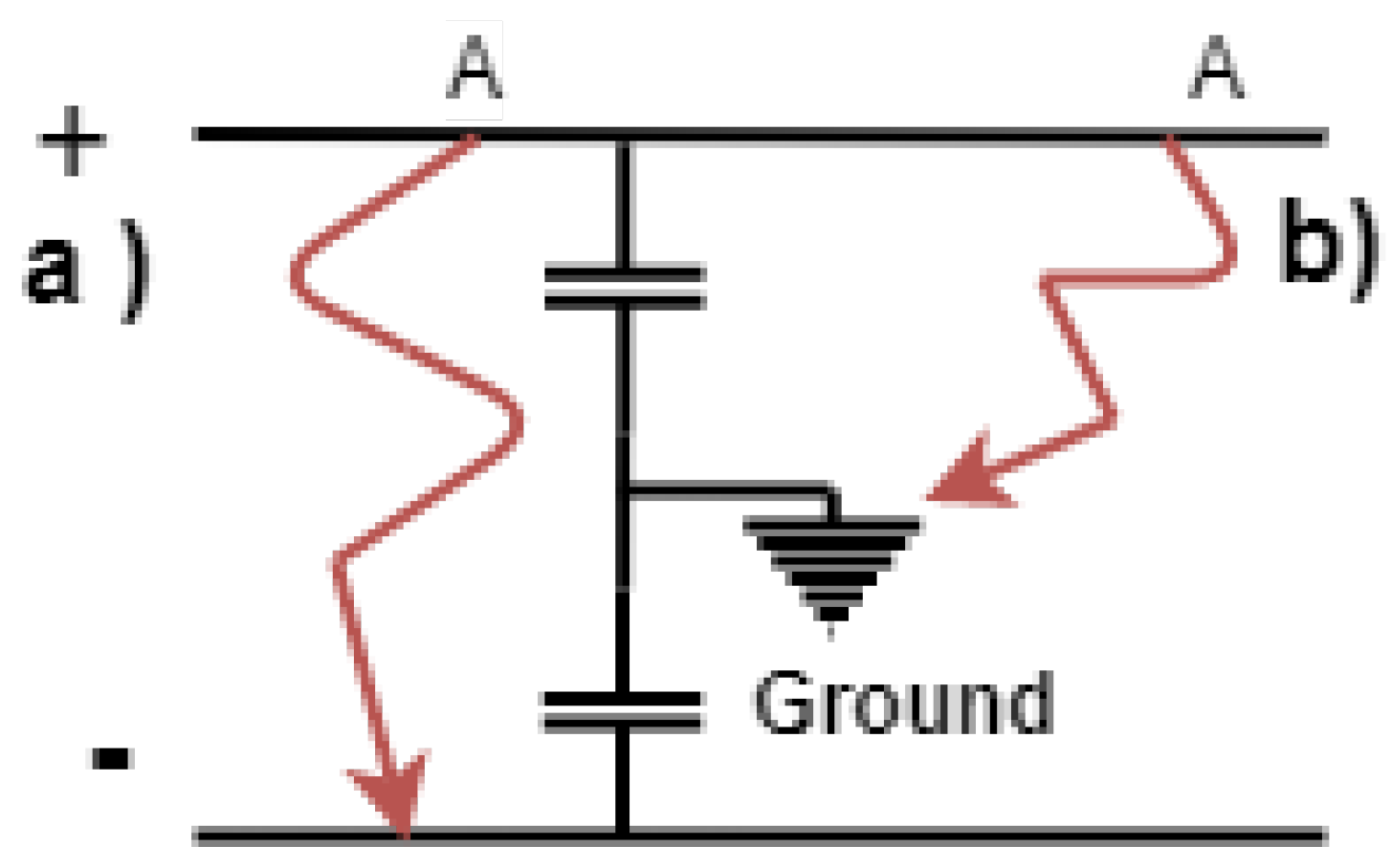
2. DC Microgrid Faults

A DCMG is defined as a MG in which the power interchange is given in the DC bus [19,38]. A DCMG may be powered from AC sources, although these sources must be connected to the DCMG through AC to DC interfaces (power inverters) [17]. Figure 1 shows a conceptual diagram of a DCMG with the location of the protection devices (PDs) that are covered in this document.
Faults in DCMGs can be divided into two principal types: the short-circuit fault current, and arc fault current [11]. This paper focuses on the short-circuit fault current.
Figure 2 depicts the types of short-circuit faults that may take place in DCMGs produced by over-current and short-circuit events. The following two types of faults are considered: line-to-line fault and line-to-ground fault. A line-to-line fault occurs when an undesirable connection is established between the positive and negative lines, creating a short circuit that connects the supply voltage terminals. In line-to-line faults, the wires are directly connected to each other; therefore, line-to-line faults are of low impedance, which are more dangerous, though they are easier to detect. In line-to-ground faults, one or both conductors are connected to the ground. Therefore, line-to-ground faults are high-impedance faults in most cases; nonetheless, they can be low-impact depending on the grounding setting used for the DCMG [1,39,40]. The ground fault is the most common type of fault in industrial systems [19].
Concerning the behavior of the fault in DC systems, in steady-state operations, if the current ripple is small, it can be affirmed that the effect of the inductance is negligible. However, under a short circuit, the CB must act by opening the circuit which produces a quick change in the current; under a fault, the effect of the inductance is considerable, and over-voltages are generated. These over-voltages may produce arcs in terminals of the CB. It is important to mention that the arc is easily extinguished in AC systems where the voltage waveform crosses through zero; however, this does not occur in DC systems in which the voltage waveform is constant and not crossing through zero. In consequence, arc-extinguishing devices are required to effectively clear faults in DCMGs [41,42]. Therefore, protection systems for DCMGs must be faster than those of AC systems. In DCMGs, protection must be configured for all faults on the upstream side of the microgrid because all resources feed the faults, which can have different characteristics in terms of magnitude, wave-front, fault current direction, and operation mode (island or grid-connected modes).
Fault response characteristics of DC systems can be divided into (a) transient state and (b) steady-state. These correspond to the transient part of the fault injected from the DC connection capacitors, the converter cable discharge, and the steady-state part injected from the power sources [43]. The transitory part of the fault currents can also be split into slow, medium, and fast front transitory. Voltage-dependent charges, converter control, and batteries cause slow front transients. Over-current in capacitors used as filters cause medium front transients, while recovery voltage transients at the opening of the protective devices (PDs) cause fast front transients [44,45].

3. DC Circuit Breakers

CBs for DCMGs have basically been composed of fuses, MCBs, SSCBs, and HCBs. All of these circuit breakers are still in use. This section explains their characteristics in detail, as well as their most relevant technical aspects.

3.1. Fuses

The fuse consists of an element in the form of a metallic conductor with a pair of contacts between them, and a box or cartridge to carry the fuse element. Depending on the voltage level, the cartridge is usually fitted with a device using material such as quartz sand for arc extinction inside [46,47]. The principle of operation of the fuse is the heating effect of the electric current. If the current passes through a conductor with a certain resistance, the loss due to the resistance of the conductor dissipates in the form of heat. Under normal operating conditions, the heat produced in the fuse element is easily dissipated into the environment due to the current flowing through it. When a fault occurs, such as a short circuit, the current flow through the fusible element exceeds the prescribed limits. This creates excess heat, which melts the fuse and breaks the circuit [48].
Fuses are usually made of copper or silver and are mainly installed in series with the line. During a fault, the heat from the increased current blows out the fuse, causing the line to open. Fuses are used as the simplest and most economical form of protection in DC systems [21].
The selection of a fuse for an ACMG requires a response time in the range of 10–100 ms to operate and interrupt the fault; however, the nature of a DCMG requires a maximum operating time of 0.5 ms, which represents a limitation [18,49]. For the selection of fuses, it must be guaranteed that the time constant of current rise during the fault is lower than a certain limit, since a slow rise in temperature allows the heat-absorbing material to extinguish the arc [19]. Fuses are ideal for applications in low-inductance DC systems, because the time for the fuse to blow out must be minimal [50]. Although a fuse is a very simple and inexpensive form of protection, it has several disadvantages: it must be replaced after operation and does not have the possibility of discriminating between a transient and a permanent fault [50]. Additionally, when a fault occurs in a single line, fuses only isolate the failed pole, leaving the other pole active; despite this, fuses are considered a good option to protect batteries and photovoltaic systems when trip time and cost are considered, as well as the protection of load-feeders working together with mechanical switches and relays [39]. In the Ref. [51], fuses were considered as a viable alternative to mechanical DC breakers; however, fuses installed in DCMGs must be provided an auxiliary device to extinguish the arc produced in the opening of the fuse during a fault. The authors in the Ref. [51] recommended a time constant to faults of >6 ms; however, this could decrease the fuse’s ability to interrupt the current and extinguish the arc. In the Ref. [52], a detailed analysis of fuses used in power converters was presented. Fuses were found to be an effective means of protection, although the required amount of capacitance at the output of the voltage-balancing converter can be high, which affects the total cost of the system; therefore, in terms of power converters, the ideal application is to use the fuses as backup protection for the main switch. Fuses are not recommended as backup protection in DCMGs with ring configuration, since in this case, there are bidirectional current flows which require a communication system and the isolation of the cable in case of a fault [52].

3.2. Mechanical Circuit Breakers

MCBs are devices that use mechanical parts to interrupt the flow of current in the event of a fault. The operating mechanisms of MCBs can be divided into hydraulic, spring, pneumatic, and magnetic [21]. Spring and magnetic operating mechanisms are more common in vacuum CBs (VCBs). When a MCB reacts to a fault, its moving contact starts to separate, and the contact area is reduced. The current density increases and the energy begins to evaporate the metal, resulting in a plasma arc, which restarts due to the capacitance and inductance of the system. Although the contacts are physically separated, the arc keeps the current flowing. As the contact separation increases, the degree of the arc column is influenced by the characteristics of the surrounding medium. The arc current will be terminated when the arc plasma becomes a dielectric medium. Moreover, the ability to limit the current is determined by the difference between the arc voltage and the system voltage [53]. To mitigate the impact of the arc, several solutions have been proposed: (a) MCBs with passive current switching, (b) MCBs with active current switching, and (c) artificial current zero vacuum switch (ACZ-VCBs). In MCBs with passive and active current switching and ACZ-VCBs, a voltage opposite to the system that conducts zero-crossing artificial currents is created by a resonant inductive (L) capacitive (C) series circuit [20]. In the passive switching method, when the switch is open, a current flows through the LC circuit with a capacitor that has not been pre-charged, and it starts to oscillate and creates a zero crossing current, in which case the mechanical switch completely interrupts the current flow, increasing the voltage to a certain specific value. Once the voltage reaches such a value, the current flows to energize the energy-absorbing circuit, which is, in most cases, a metal oxide varistor (MOV) used to dissipate the stored energy.
Figure 3a shows a MCB with passive commutation. Its components are: (1) the branch of the switch, (2) branch of the series resonant circuit, and (3) branch of the energy-absorbing circuit. In the case of active switching, the capacitor has already been pre-charged, and when the switch opens, the capacitor injects a negative current equal to the fault current to make a zero crossing of the current. During the interruption process, the magnetic energy is stored in the inductor and the varistors are connected in parallel with the switch to mitigate the over-voltage and absorb the energy stored in the inductor. Figure 3b shows the mechanical switch with active current switching.
In the VCB, once the contacts are separated, the arc current generated across the electrodes is extinguished using a vacuum chamber so that a vacuum arc is initiated at the contacts. This arc is then extinguished and the conductive metal vapor condenses on the metal faces, and the dielectric strength in the electrode is reduced. VCBs feature arc voltages lower than 100 V, and they do not limit the arc currents of MVDC MG. VCBs are effective because they avoid re-ignition of the arc after zero current [54]. The most frequently used approach of VCBs in MVDC interruption is based on artificial current zero (ACZ). Figure 4 depicts a general circuit of an ACZ-VCB. The interruption process begins with the separation of the VCB followed by the formation of a vacuum arc conducting line current i1. As the electrode gap of VCB reaches a certain safe stroke to withstand the recovery voltage, the commutation circuit breaker (CB) injects a high-frequency oscillating commutation current i2, which is generated by discharging a pre-charged commutation capacitor C1 through inductance L1. In consequence, the superimposition of i2 forces i1 to drop to zero. Then, VCBs can be interrupted by extinguishing the vacuum arc. A metal oxide arrester is used to suppress the over-voltage across the VCB [55].
The main advantage of MCBs is low losses and low costs; however, the fault-clearing time is between 30 and 100 ms [56,57], which is too high for DCMG requirements.

3.3. Solid-State Circuit Breakers

This section contains the description of SSCBs, the most recent advances in terms of semiconductors and materials, and also the most recent topology of SSCBs reported in the technical literature.

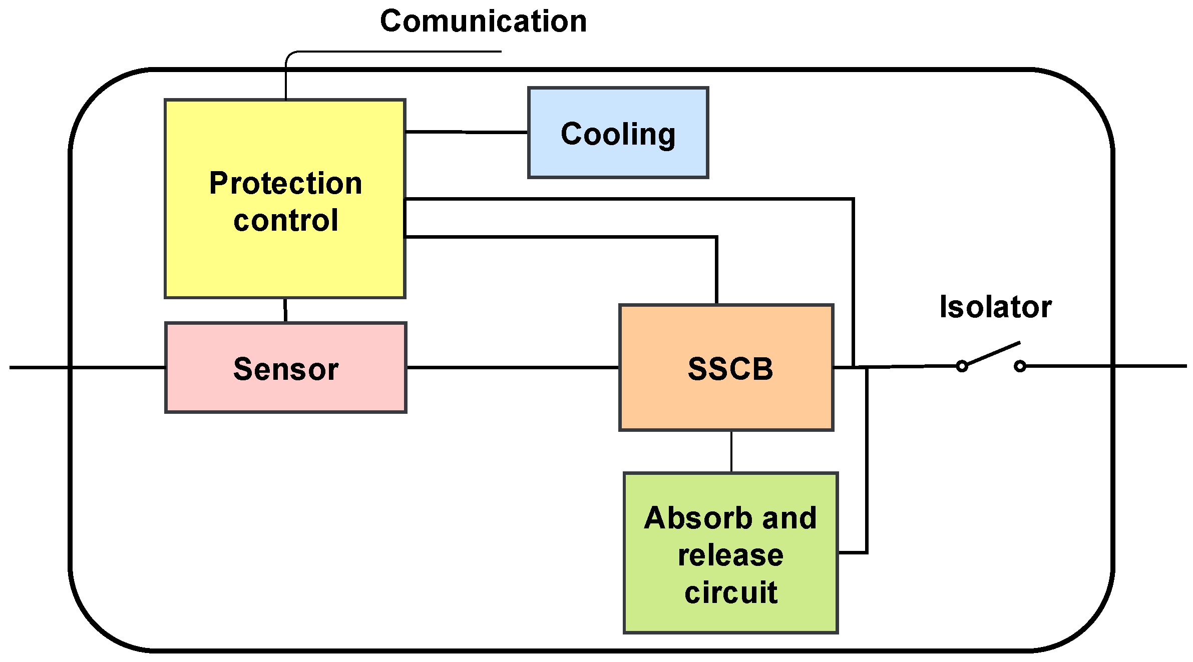
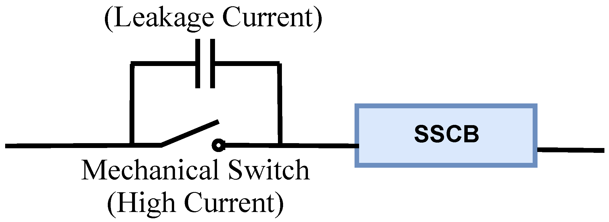
3.3.1. SSCBs General Description

SSCBs do not have mechanical moving parts to operate in case of electrical faults, since this is performed by semiconductor devices. Compared to MCBs, SSCBs are much faster and feature greater accuracy in controlling their operation. With the rise of power electronics in the 1970s, the SCR thyristor appears as one of the first solid-state switches. With the development and contribution of power control systems between 1980 and 1990, the growth of solid-state switches became remarkable, whose predominant material is silicon (Si), such as SCR [58], IGBT [6,59,60], IGCT [61], GTO [62], and CS-MCT [35]. Si devices have a high level of maturity and are commercially available with a wide range of voltages and currents. SSCBs have the following advantages: fast operating times of less than 100 μ s, no arc, no sound, no gas emissions, long service life, and high reliability and applicability [8,63,64]. However, SSCBs have the disadvantage of presenting high power losses, and being very expensive and large, due to the need for heat sinks [21]. Another group of SSCBs is the devices proposed since 1989 [65], in which the predominant material is a wide band gap (WBG), such as SiC JFETs [66], SiC ETO [67], SiC MOSFETs [68,69], SiC SITs [70], GaN HEMTs, and GaN MOSFETs [15]. WBG semiconductors exhibit superior material properties than silicon ones, which enable the operation of power devices at higher-temperature operation, higher blocking voltage capability, and higher switching frequencies [34,71]. Although WBG semiconductors offer significant improvement over silicon ones in power efficiency, switching frequency, and operating temperature, their proliferation into the mainstream power electronic market is impeded by high device cost and reliability concerns, and this is mainly because the WBG technology itself is still evolving towards its maturity [56].
SSCBs can be damaged due to overvoltage of the inductive components of the system, hence the importance of reducing this voltage for the safety of the device. To protect the solid-state switch from overvoltage at the moment of opening, additional elements are required, such as resistors, capacitors, diode (RCD) Snubber Circuits, metal oxide varistors (MOV), and freewheeling diodes [10,72]. In the Ref. [40], the authors described the advantages and disadvantages of different SSCB snubbers: the metal oxide varistor (MOV), single snubber capacitor, dissipative snubber, RC snubber, and RCD snubber. They concluded that RCD snubber is the best option and is able to avoid the oscillation between C and L by using a fast recovery diode to clamp the changing voltage; it is, therefore, a suitable candidate for medium-capacity applications [40]. The protection control, heat cooling system, sensor, and damping system for a SSCB are depicted in Figure 5.
One of the main drawbacks of SSCB is the lack of galvanic isolation in the open state. This can be overcome by adding an auxiliary circuit based on two mechanical switches in series with the SSCB [21] (see Figure 6). This circuit is opened after the trip of the SSCB, guaranteeing complete isolation between load and supply. Galvanic isolation of SSCBs is a key feature for achieving fault detection, isolation, and DCMG reconfiguration. The mechanical switches that provide physical isolation are as follows: (1) a mechanical switch to handle the high current that appears through the SSCB when the SSCB interrupted the fault current, and (2) a secondary mechanical switch for interrupting the leakage current during isolation [43,73,74].

3.3.2. Recent Developments of SSCBs

The following paragraphs show the most recent developments of SSCBs in terms of the type of semiconductors and material used:
In the Ref. [75], the authors compared the switching waveforms of Si GTO and SiC GTO switches. The latter is known as an automatic turn-off device that controls high voltages and large currents. GTO is preferred for DC applications because it has an independent gate for turn-on and turn-off. The results showed Sic GTO times of 2.21 μ s, which are lower than Si GTO times of 10.82 μ s.
In the Ref. [76], a SSCB based on IGBTs was implemented in a DCMG. The designed SSCB was capable of low-end lighting protection applications and tested at 50 V. A 15 A continuous current rating was obtained, and the minimum response time of the SSCB was nearly 290 times faster than that of conventional AC protection methods. The development of this technology shows promise for the future of integrated power systems; nonetheless, the cost associated with these new technologies remains an obstacle in the growth of commercial DC systems.
In the Ref. [61], a new SSCB was designed based on IGCT technology for an aircraft DCMG. The authors proposed a new IGCT-based SSCB that uses Y-shape coupled inductors that forces the current to zero to isolate short-circuit faults. With this implementation, there is no need to add a snubber or clamp circuit across the IGCT because the Y-shape coupled inductors drive inductive currents to zero before the IGCT commutates off. They obtained a SSCB with an efficiency of 99.94%, and operating time of around 20 μ s.
In the Ref. [10], a suitable IGBT for low-voltage (around 400 V) fault protection of a DCMG was proposed. The simulation results showed that the SSCB acted reliably and the fault current dropped to zero within 15 μ s until the fault was removed from the system and reconnected within 8 μ s, while the rest of the system continued to operate normally. However, the high conduction loss and cost of the semiconductor breakers technology was considered as the main obstacle to their wider use in electrical protection applications.
Si IGBT-based breakers have also been proposed to interrupt fault currents In the Ref. [10]. However, these breakers feature relatively high power losses due to the finite conductivity modulation effect of the IGBT [77]. Besides, the maximum current interruption ability of these breakers are also limited by the saturation current of the IGBT which reduces the short-circuit requirements from 10 to 5 μ s. However, Si IGBT would reduce the on-state losses to increase the channel width-to-length ratio [78].
In the Ref. [22], Si MOSFET, Si CoolMOS, SiC MOSFET, and SiC JFET with the lowest on-resistance Rds (on) for a rated breakdown voltage devices were studied. The SiC junction-gate field effect transistor (JFET) has the best maximum turn-off capability, the maximum current that a switch can interrupt, and the highest peak power density.
In the Ref. [68], a photovoltaic-driven SSCB with latching and current-limiting (LCL) capabilities (SSCB-LCL) was proposed. In case the load current is exceeded, the SSCB-LCL limits the load current during a pre-configured time by the user. If the fault persists, after the pre-configured time has elapsed, the load is disconnected from the input. External commands were also included for controlled load disconnection or restarting the SSCB-LCL. This circuit contains very few components, does not require external supply, and provides a large bandwidth control signal.
In the Ref. [17], the authors proposed a SSCB that detects short-circuit faults by sensing the drain source voltage, in which case it extracts power from the fault condition to turn off and stop a SiC JFET. The authors proposed a new two-terminal for the SSCB that can be placed directly on a circuit branch without requiring any external power supply or additional wiring.
In the Ref. [41], a semiconductor DC circuit breaker using SiC static induction transistor (SiC) SITs was investigated in applications for data centers at 400 V. SiC SITs have extremely low on-state resistance and a very large safe operating area. The experimental results showed that the SiC SIT’s fault current decayed to 0 A within 20 μ s.
The authors in the Ref. [15] experimentally demonstrated the feasibility of using 650 V GaN bidirectional devices in SSCB applications. GaN devices outperform silicon MOSFETs with regard to the on-resistance value during operation ( R d s ) versus the breakdown voltage, allowing a further increase in switching frequency and efficiency, and reduction in physical size. The authors reported a new bidirectional SSCB, which comprises a single 650 V, 200 m Ω dual-gate, bidirectional, normally-on, GaN-on-Si HEMT as the static switch, and a fast-starting isolated DC/DC converter and a diode bridge as the fault detection and protection driver. When a fault occurs, the switch opens, bringing the current to zero in 0.8 μ s.
In the Ref. [57], a discussion on the basic concept and general design methodology of the intelligent tri-mode SSCB (iBreaker) was provided. Commercial LVDC GaN FETs in various SSCB designs that offer m Ω -resistance and passive cooling were presented. The SSCB ibreaker identifies and exploits a distinct pulsewidth modulation (PWM) current-limiting (PWM-CL) state in addition to conventional on and off states in a bidirectional common-inductor buck topology without needing additional semiconductor power devices. The IBreaker can operate in the "on" state for continuous conduction of normal load currents, or in the "off" state to interrupt fault currents. In addition, it can operate in the PWM-CL state with a moderate overcurrent for a short period of time to facilitate intelligent functions, such as soft startup, fault authentication, and fault location. The iBreaker switches from the PWM-CL to the off state if it deems the overcurrent condition to be a true short-circuit fault rather than a startup scenario after a short time-period. The tri-mode iBreaker quickly limits a detected overcurrent to 2–3 times of the rated nominal current within a few microseconds, and conducts a fault authentication process within a preset time window (typically a few milliseconds) while operating at a relatively low overcurrent. This significantly reduces the stress on the wiring and power semiconductor devices, and reduces the current rating and cost of semiconductor switches.
In the Ref. [79], the formation of Ohmic Contacts in SSCBs was presented. Ohmic contacts are necessary since they ensure the flow of signals and power from the semiconductor to the peripherals. However, the arrangement of ohmic contacts in p-type 4 H-SiC is still a highly discussed subject, due to the intrinsic challenge of acquiring a low value of specific contact resistance in p-type WBG semiconductors. Moreover, the shortage of metals that provide a low Schottky barrier to p-type SiC and high ionization energy of the Al dopant renders the arrangement of a tunneling contact to a p-type SiC extremely troublesome.
In the Ref. [80], a 4 H-SiC MOSFETs low-inversion channel mobility was reported. This 4 H-SiC MOSFETs revealed stable behavior when at room temperature, as well as for moderate stress periods. However, with rising temperature (>150 C) and stress periods, a significant threshold voltage instability was found to occur [81].
In the Ref. [80], it was indicated that CBs based on GaN should ensure much better efficiency with respect to CBs based on SiC because of its higher critical electric field and greater electron mobility. However, GaN also suffers from many manufacturing problems concerning the more advanced SiC technology, such as the insufficiency of high-quality freestanding substrates, which prohibits the advancement of vertical structures in the internal design of transistors [79,82].
There are a number of 10 kV-class SiC switches that are currently at various stages of development at Cree, Inc., Durham, NC, USA [83]: (1) SiC MOSFETs, (2) SiC GTOs and thyristors, and (3) SiC IGBTs, including n-IGBTs and p-IGBTs of this family. Table 1 compares several physical properties of different semiconductors according to the type of material. It is observed that the electric breakdown field of Si is considerably smaller than that of GaN at SiC [84].
In the Ref. [85], a short cathode metal oxide semiconductor controlled thyristor (CS-MCT) was proposed in a 400 V SSCB, which achieved a 30% reduction in energy loss compared to using a Insulated Gate Bipolar transistor (IGBT). However, this kind of SSCB is only able to interrupt unidirectional fault currents and requires an additional DC source to pre-charge the commutating capacitor, thus increasing the circuit complexity and limiting its applications.
In the Ref. [35], a novel SSCB which uses the CS-MCT was proposed for DCMG protection. The SSCB offers interruption capability before the main switch is turned on. When a fault takes place, the switch opens, bringing the current to zero in 2–3 μ s. The practical value and the feasibility of the SSCB were validated by a 600 V/15 kW prototype.
Table 2 compares different switches. Note that the CS-MCT provides lower conduction loss than that of the IGBT, the SiC mosfet, and the thyristor. Compared with the IGBT or the SiC Mosfet, the CS-MCT and the thyristor can offer lower conduction losses and stronger tolerance to current and voltage surges, but need additional forced commutation technology. As a result, the breakers based on thyristors or the CS-MCT are attractive in terms of higher power efficiency and more robust fault isolation [35].
In the Ref. [86], it was indicated that thyristors are superior to IGBTs in terms of their rating, cost, drive circuit design, and reliability. Moreover, thyristor-based circuit breakers are a common approach to tackle the conduction losses of solid-state circuit breakers. In fact, thyristors constitute one of the best power electronic types of switches from the point of view of conduction losses, the rating, cost, symmetric blocking capability, and reliability aspects; however, this breaker needs additional commutating circuits.

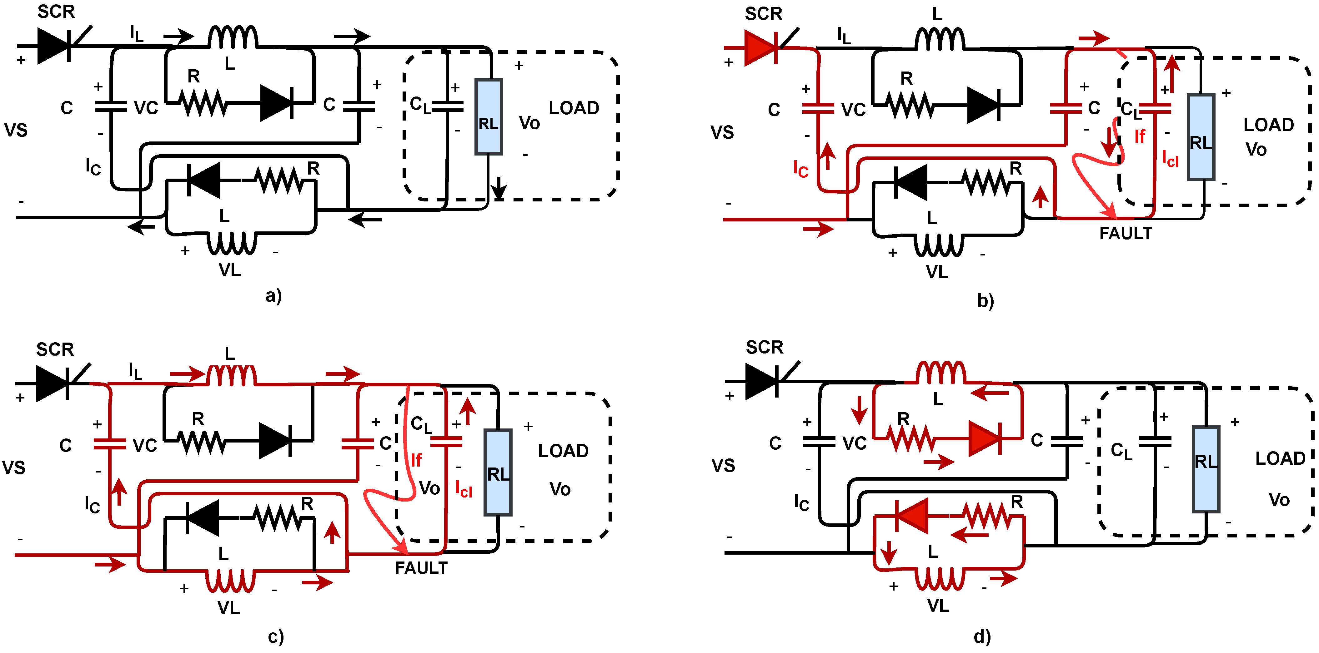
3.3.3. Z-Source: The New Generation of SSCBs

Z-source circuit breakers (ZSCBs) constitute one of the most recent lines of research and development of circuit breakers for over-current faults in DCMGs. ZSCBs feature natural switching, automatic disconnection of the fault load, simple control circuit, isolation of the fault source, and inherent coordination capacity. Furthermore, the ZSCBs’ impedance fault limits the fault current and can operate in bidirectional mode. The ZSCBs can take the transient current that occurs at the fault and pass it through the ZSCB capacitor so that the semiconductor-controlled rectifier (SCR) is disconnected. Figure 7 illustrates the states through which the ZSCB switch passes in the event of a fault [58]. The operating states are described as follows: In the steady state, the current passes through the inductor to the load, since the inductor behaves as a short circuit, and the capacitors as an open circuit (Figure 7a). Once the fault occurs, the current passes through the capacitors of the ZSCB to disconnect the SCR naturally. In this state, the capacitor currents increase and cause the SCR to switch, disconnecting the fault source, and a control circuit removes the SCR gate voltage before the SCR voltage becomes negative (Figure 7b). In the next state, two series LC circuits are connected to the fault and the load, initiating a resonance until the inductor voltage becomes negative (Figure 7c). Then, the third state begins, in which the diodes and resistors conduct until the current decays to zero (Figure 7d) [58].
In the Ref. [58], some features of ZSCBs are described, where the most relevant are: (1) Fast operation, since the ZSCB breaker operates with natural commutation; (2) instead of requiring a circuit to detect a fault, the control circuit only needs to detect that the SCR has commutated off, or that the current has dropped below a certain level; (3) the source and SCR do not experience the fault path current; (4) cascaded breaker coordination is inherently automatic; (5) the fault current may be limited by the impedance of the z-source breaker, making the system more fault-tolerant; and (6) the z-source circuit can be modified with bi-directional devices.
In the Ref. [58], the authors reported a ZSCB that operates in a system with a source voltage of 120 V and a current of 10 A. As a drawback of this paper, the switch opens, bringing the current to zero in 100 μ s. This problem arises due to the fact that the z-source series capacitor stays charged even after the fault is interrupted or cleared.
In the Ref. [87], the issues suffered by ZSCBs are presented: (1) a high starting current in the main thyristor SCR. (2) unwanted power flow in the load during the commissioning and reclosing of ZSCBs. (3) negative current flow through the load at the starting/reclosing of the ZSCB.
In the Refs. [88,89], a topology is proposed to the original ZSCB, in which a couple of inductors are added, resulting in a 30% reduction in the size of the switch and a 25% weight reduction, as well as the possibility to decrease the original design by one capacitor, obtaining the same functionality.
In the Ref. [90], the authors proposed a bi-directional Z-source topology (Bi-ZSCB), and they successfully conducted experimental tests for validating the topology. This contribution is important, since in DCMGs, there are different sources of power supply connected to the DC bus, and the energy flows in a bidirectional way. The authors also reported a topology for measuring artificial faults that gives the switch the ability to operate under different conditions.
In the Ref. [91], a Bi-ZSCB with a coupled inductor with re-closing and re-breaking capabilities was introduced. This breaker can operate with a single coupled inductor for bi-directional power flow. Therefore, the size of the inductor was optimized to 50%; thus, the total cost of the breaker is minimized.
In the Refs. [92,93], a solid-state breaker circuit for DCMG is proposed, which replaces ZSCB LC elements by a transformer, decreasing the amount of elements in the circuit and decreasing the weight. The switch was called T-Z-source Circuit Breakers (T-ZSCBs).
In the Ref. [94], a new bidirectional T-ZSCB was proposed, and the authors indicated that this device is more efficient than previous ones reported in the technical literature; the reason is that this new topology has only two SCRs and two diodes. The diode in the steady-state path was removed, thereby reducing the on-state loss by more than 40% compared with the conventional bidirectional ZSCBs and bidirectional T-ZSCBs. The soft starting circuit was designed to protect SCR from over-currents when the line is started. The simulation and experimental results showed that the soft-starting circuit can effectively reduce the over-current of the SCR.

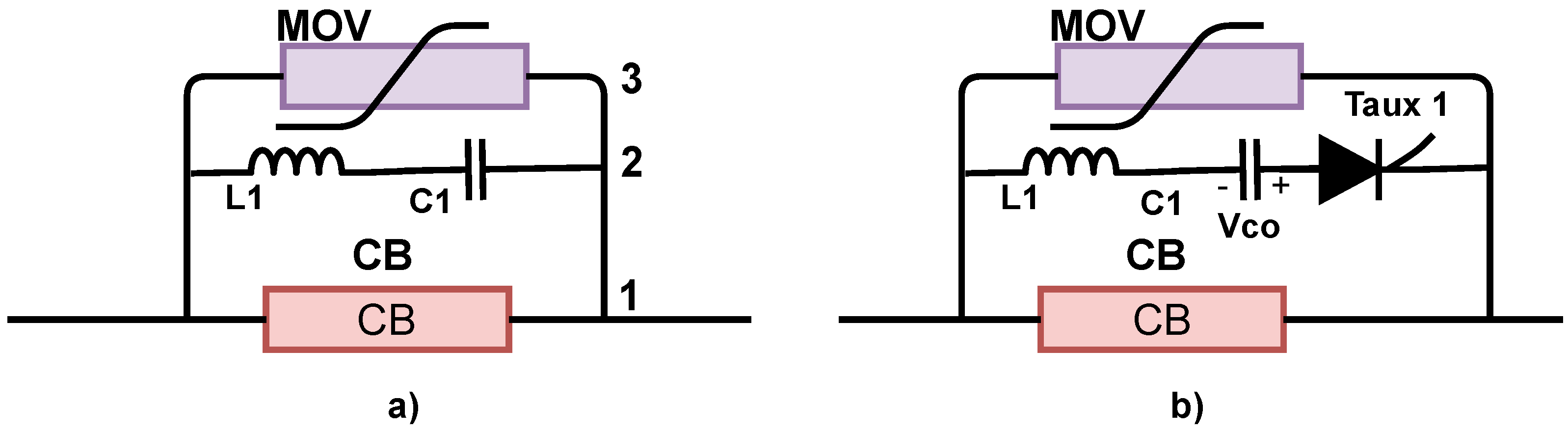
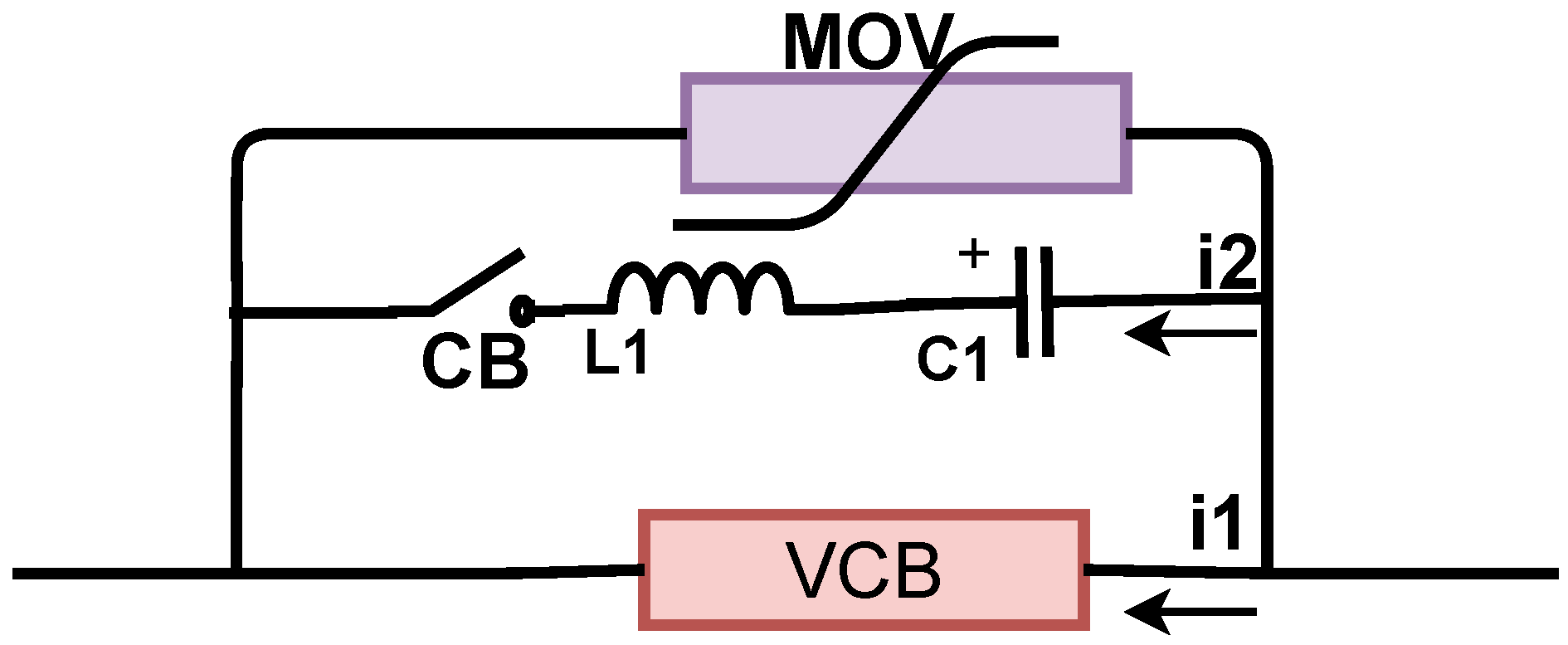
3.4. Hybrid Circuit Breakers

This section presents the description of HCBs and their most recent advances in terms of semiconductors.

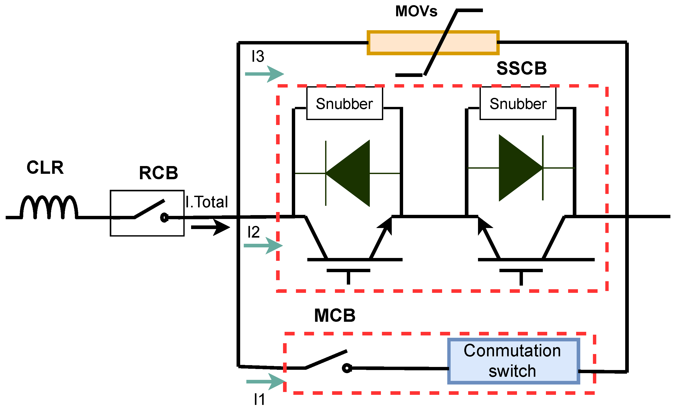
3.4.1. General Description of HCBs

HCBs are a combination of the best features of MCBs and SSCBs in a single device, overcoming the drawbacks of both devices. HCBs have small conduction losses, very short operation times, long life, high reliability, and do not require special cooling equipment. Additionally, they feature simpler control, and more compact volume [95], resulting in a new direction of research and development of switches for engineering applications. Figure 8 illustrates the current path in the different states for HSBs—in normal condition, the current I 1 passes through MCB. When a fault is identified, the MCB starts the opening of its contacts and sends a turn-on signal to the SSCB. The established arc voltage is increased until it exceeds the voltage drop of the SSCB. In this case, the current can be naturally commutated from the MCB to the SSCB. The SSCB continues conducting current I 2 until the MCB is able to block the full voltage. At this point, the SSCB is turned off and the voltage increases quickly because of the circuit inductors. While the voltage reaches its breakdown value, the fault current I 3 commutes to the MOV to clamp voltage and approach the current to zero. Finally, when the fault current is zero, the RCB is opened to isolate the faulty line from the DC grid to protect the MOV from thermal overload [63]. Moreover, a current-limiting reactor (CLR) in series with a residual circuit breaker (RCB) was added to limit the rate of rise of currents and to provide complete galvanic isolation.

3.4.2. Recent Developments of HCBs
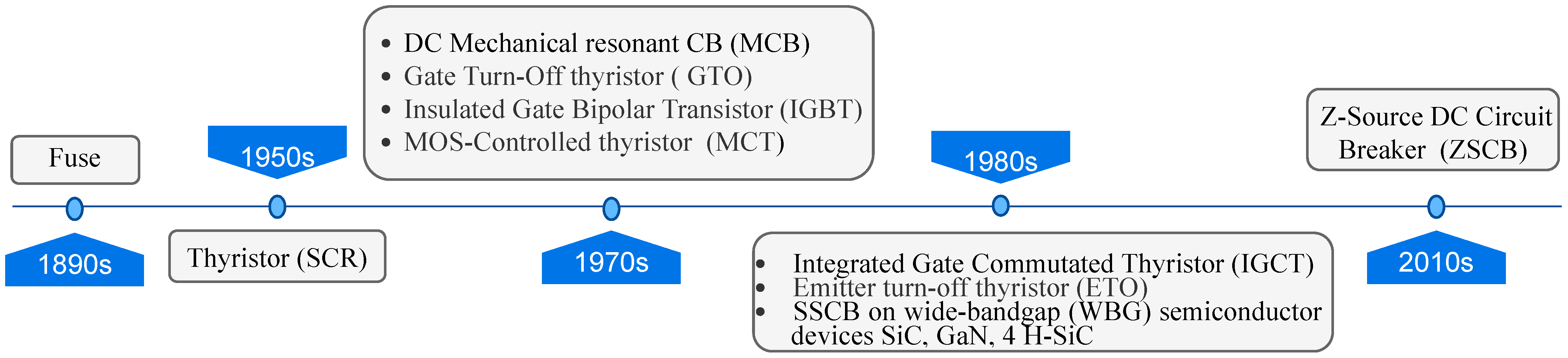
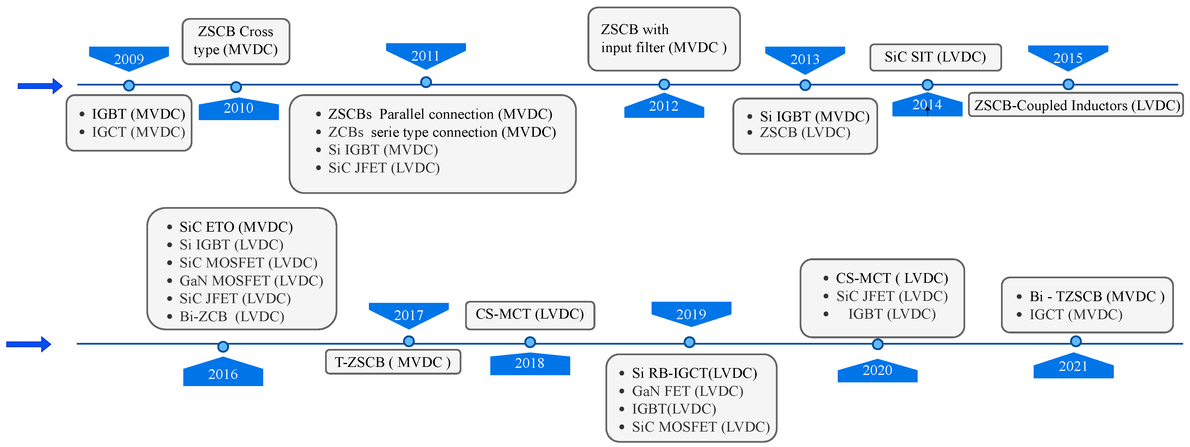
The following paragraphs have the purpose of showing the most recent developments for HCBs in terms of the type of semiconductor and material used:
In the Ref. [96], the authors compared the general characteristics of press pack IGBT and injection-enhanced gate transistor (IEGT) used in HCBs. Basically, the maximum blocking voltage, maximum turn-off current, surge current, d i / d t , on-state voltage, drive power, failure mode, and voltage balance for series were compared. The IEGT was more suitable for natural commutation than HCBs when the system fault current was not very high. Comparatively, IGBT and IEGT were more suitable for very high current interruption, and IEGT was the superior selection based on their experiments. The advantage of HCBs is that they have very low on-state losses. Furthermore, the current can be turned off independently from a natural zero crossing. However, HCBs are very expensive and their speed is highly dependent on the mechanical parts of the system [94]. Consequently, a standard mechanical circuit breaker cannot be used because of its lack of speed [23], which represents a limitation for DCMG protection.
To improve the speed of HCBs, several fast-acting mechanisms have been proposed to reduce the commutation time of MCBs to SSCB, such as Thomson coil and piezoelectric actuators, which act in hundreds of microseconds. However, in experiments performed with HCBs, the whole process takes between 0.5 and 5.5 ms [97,98].

4. DC CB Evolution

This section has the purpose of showing the DC CB evolution. DC CBs have been evolving for more that 100 years. For this reason, the time-line is divided after and before the definition of DCMGs. Figure 9 corresponds to the evolution of DC CBs before the emergence of DCMGs, while Figure 10 illustrates the evolution of DC CBs after the emergence of DCMGs.
Electrical fuses were patented over 100 years ago to operate in DC networks in the late 1890s [48]. The silicon SCR thyristor SCR appeared as a superior alternative to the mercury arc rectifier in the 1950s for application to various AC power electronics devices, since its switching is based on zero crossing of the current [99]. In 1980s, there was a considerable evolution in DC CBs: (a) a DC MCB with LC series resonance to create zero crossing of the fault current and mitigate the arcing problem in switching for HVDC networks was proposed [20]. In fact, the LC series resonance concept served as the basis for the development of the ZSCB for MVDC and LVDC DCMG applications. (b) With the advent of PWM, the development of auto turn-off devices having fast switching and high withstand capability was necessary. Gate Turn-Off (GTO) thyristors meet this requirement and easily withstand high voltages and high currents. The gate turn-off thyristor (GTO) has all the advantages of that of the SCR, and can also be turned off when desired through its gate. Unfortunately, its gate drive current requirements are difficult, making the drive circuit very complex [100]. (c) IGBTs have the best characteristics of MOSFET and BJT transistors with the speed characteristics of high switching speed and high voltage capability, being quite practical in the low- and medium-current ranges. Nonetheless, IGBTs were not suitable for simultaneous high-voltage and high-current operation [101]. (d) Another alternative was the MOS gate thyristors, such as the MOS-controlled thyristor (MCT) and base resistance-controlled thyristor (BRT) for high-voltage applications, due to their single gate drive capabilities and low forward voltage drops. However, as these devices lacked the current saturation feature, they showed much poorer short-circuit SOA characteristics compared to IGBTs [78,99].
In the 1990s, considerable progress was achieved: (a) IGCT, which has all the advantages of other thyristor-type devices, such as SCR and GTO, was proposed. IGCT features a high voltage, and current and surge current capabilities, which satisfy the high current trend of solid-state switch. The switching speed of IGCT is about six times slower than that of IGBT, but that is not really a problem in switch applications, since IGCT-based SSCB is at least 900 times faster than a typical EMCBs [100]. (b) ETO, a hybrid device of MOS and GTO that combines the advantages of GTO and MOSFET, was proposed. (c) WBG semiconductors exhibit material properties superior to silicon, which allow operation of power devices at higher operating temperature, higher blocking voltage capability, and higher switching frequencies. In the Ref. [78], the authors presented recent applications with SiC, GaN, and 4H-SiC materials, such as SIC ETO, SIC MOSFET, SIC SIT, SIC JFET, and GaN MOSFET. In 2010, a novel alternative for DCMG protections for MVDC and LVDC appeared: the Z-Source DC circuit breaker, ZSCB. This circuit breaker uses a z-source L-C circuit to automatically switch a main path SCR during a fault. Compared to existing DC circuit breakers, the z-source circuit breaker features very fast tripping, easier control, and the source does not experience a fault current [58]. Figure 10 corresponds to a time line after the definition or emergence of DCMGs.
After the definition of DCMGs, DC CBs have evolved quickly, trying to satisfy the DCMG requirements. Figure 10 shows the CBs for LVDC and MVDC in chronological order obtained from the literature review that were validated with experiments, prototypes, or simulations in the last 20 years. The participation of the different technologies and topologies proposed as candidates for DCMG protection can be observed. IGBTs [6,59,60,73,75] (2009, 2011, 2013, 2016, 2019) and IGCTs [61,96,100] (2009, 2021), the most widely used SSCBs for MVDC and LVDC DCMG applications today, due to their characteristics and maturity, have been available for more than 20 years [100,101]. However, in recent years, the number of SSCBs proposed as candidates for DCMG protection has increased. It should be added that ZSCBs [58,87,88,89,90] (2010, 2011, 2013, 2015, 2016) and derived topologies, such as TZSCBs [57,92] (2018, 2020, 2021), are under development, which have proven to be strong candidates for DCMG protection of SSCBs. MCTs [35,85,102] (2010, 2021, 2021) were out of the market due to their worse short-circuit SOA characteristics. However, CS-MCTs are presented as a candidate for DCMG protection, with very good results. WGB SSCBs are continuously evolving as an alternative to replace Si SSCBs: SiC ETO [67] (2016), SiC MOSFET [69,81] (2010, 2016), SiC JFECT [66,68] (2011, 2016, 2020), SiC SIT [70] (2014), and GaN FET [15,80] (2016, 2019).

5. Future Challenges

The bibliographical review shows that CBs in DCMGs are still a technology under evolution and study. Each CB has its own advantages, but also has its drawbacks; the weak points or limitations of CBs are being addressed by researchers around the world to better meet the requirements for their application in DCMGs. At the present time, until the technology is consolidated, it is not possible to know which of the CB will predominate over the others. Their strengths and weaknesses are manifested in different aspects; therefore, it is not possible to define a definite winner in a strict technical sense. Nonetheless, to facilitate the decision-making of engineers and designers of DCMGs, Table 3 summarizes the main advantages and disadvantages of the CBs considered in this paper. It can be seen, for example, that despite the fact that fuses are not expensive, they are unable to distinguish between a transient and a permanent fault; regarding operation speed, MCBs are not as fast as SSCBs; nonetheless, they feature low cost and low power losses. On the other hand, HCBs present low power losses, but are expensive when compared with MCBs or fuses. In particular, the fourth column of Table 3 provides a comparison in terms of operation speed. It can be seen that in general terms, new technologies of CBs have a tendency to be faster, since speed of operation is a fundamental aspect of modern DCMGs. A more detailed account of advantages, disadvantages, and future challenges of each CB approached in this paper is carried out in the following paragraphs which expand and complement the information presented in Table 3.
Fuses are the simplest and most economical protection device for DCMGs, which can be installed in systems that have low inductance. For DC systems that have high inductance, there is a risk of the production of a permanent arc in the terminals of the fuse after its operation. Fuses are commonly used in low-cost DCMGs for protection against fire or explosion; this breaker does not fully protect the elements of the MG, requiring other complementary protection devices to satisfy the DCMG requirements. Fuses are commonly used to protect battery banks; however, as mentioned, this breaker does not fully protect the battery; basically, in this particular case, it is used to prevent fires or explosions when the battery terminals are short-circuited [21,50]. The most important challenge for this circuit breaker is the reduction of response time under fault to values below 0.5   ms , and an alternative for reaching this challenge consists of investigating heat-absorbing materials whose properties allow the arc to be extinguished with fast current rises [18,19,49]. If response times in fuses are satisfactorily reduced, they would be used as back-up protection devices in DCMGs. Another important aspect is the development of fuses that do not have to be replaced after the fault occurs; however, the development of this capacity may increase the price of the fuse, which is currently its main advantage.
MCBs is the most extended protection for ACMGs, and this is the reason why it might become one of the most promissory candidates for DCMGs. In general terms, MCBs that are used in ACMGs could be used directly in DCMGs; however, the arc produced in DC circuits is more difficult to extinguish than the arc in AC circuits. Thus, in order to preserve the useful life of the protection, the protection must be derated. In consequence, one of the challenges for the use of MCBs in DCMGs is the improvement of the active current-switching circuits, which permits mitigating the impact of the arc and preserves the useful life of the device. Another important aspect is that MCBs are very slow; in consequence, it is still necessary to achieve better operating times, less than 0.5 ms [31]. If better times are reached, MCBs could be implemented in a coordination scheme that adequately protects the system. Reaching better times for MCBs is very difficult, so researchers around the world are focusing their efforts on obtaining SSCBs or HCBs. Despite their arc-extinguishing difficulties and low operating times, MCBs are still used in DCMGs because of their low losses and low cost.
SSCBS constitute a good alternative for DCMG protection due to several advantages: (1) operating times lower than 100 μ s; (2) that it does not generate arcs under faults since there are new technologies that permit galvanic isolation; (3) that it does not produce sound because the trigger does not use any mechanical systems for operation; (4) that it does not emit gases, since there is not any chemical reaction during the operation; (5) that it has long life service for the use of semiconductors; (6) that it presents high reliability; and (7) that it correctly works for a great variety of DCMG applications (generators, loads, batteries). However, to be fully developed, there is still the challenge of reducing power losses due to the modulation effect of the finite conductivity of semiconductors [31], as well as the reduction of the current-balancing problem and construction cost in parallel technology to improve the interrupting capability [104]. Moreover, the family of SSCBs is very broad (SCR, GTOs, Mosfets, IGBTs, IGCTs, and CS-MCTs) and there is a lot of research to improve them, as evidenced in this review. In general terms, trying to put together the most relevant aspects of all papers consulted, SSCBs have, as a future challenge, the reduction of the commutation losses, while simultaneously safely increasing the switching frequency in order to decrease the harmonic frequency currents injected to the system. Two important challenges concerning WBG SSCB which could be of a promissory family for CBs in DCMGs are: (1) the acceleration of the curve of cost reduction of technology [35,94], and (2) overcoming issues of insufficiency of high-quality freestanding substrates for speeding up the advancement of vertical devices [79,82].
HCBs are the new generation of CBs that combine the best features of MCBs and SSCBs, which overcomes the drawbacks of the previous generation of CBs. Basically, it was found that HCBs have small conduction losses, very short operation times, long life, high reliability, and do not require special cooling equipment. Additionally, they feature simpler control and a more compact volume [95], resulting in a new direction of research and development of switches for engineering applications. However, it was found that there are challenges to be faced for their suitable implementation in DCMGs: (1) The first and the most important challenge is the reduction of the manufacturing costs [23,94]; if manufacturing costs are reduced, we strongly believe that HCBs will be widely used in the near future in DCMGs, and also in DC buses of ACMGs. (2) The second challenge corresponds to the reduction of the commutation time from MCBs to SSCBs that are included in HCBs by improving the technologies of fast-acting mechanisms, such as Thomson coil and piezoelectric actuators [97,98].

6. Conclusions

A bibliographic review was conducted on DCMG circuit breakers, their operating characteristics, and evolution, with an emphasis on fuses, mechanical switches, solid-state switches, and hybrid switches. It was observed that there is a very important research field to be explored regarding these devices, in order to select the ideal candidate for DCMGs. In addition, there have been very few low voltage experiments found in the literature that are applicable to DCMG protection, which presents a very wide field of research in the area of electrical protection.
According to the literature review, it is possible to affirm that in recent years, the race to develop candidate CBs for DCMG protection has been growing. So far, it has not yet been possible to replace fuses because they have the great advantage of low cost and low losses; however, they cannot be ruled out as strong candidates for DCMG protection. Current mechanical technology is expected to enable MCBs to overcome the challenge of increasing the switching speed to the order of microseconds. On the other hand, SSCBs are not far behind. SSCBs have the switching speeds and current- and voltage-blocking capabilities needed for DCMG protections; nonetheless, they are expected to overcome the challenges of high cost and high conduction losses in the near future. In fact, WGB technology is projected as a possible near-term solution over Si technology with higher temperature operation, higher voltage blocking capability, and higher switching frequency. In addition, HCBs are expected to take advantage of the evolution of MCBs and SSCBs and snap-acting mechanisms to overcome their speed and cost limitations for their future use for DCMG protections.

Author Contributions

Conceptualization, B.P.-M.; Data curation, B.P.-M.; Formal analysis, B.P.-M., N.M.-G. and J.A.V.-V.; Funding acquisition, J.A.V.-V., J.M.L.-L. and N.M.-G.; Investigation, B.P.-M., N.M.-G. and J.A.V.-V.; Methodology, B.P.-M.; Project administration, N.M.-G. and J.M.L.-L.; Resources, B.P.-M., N.M.-G. and J.A.V.-V.; Supervision, N.M.-G. and J.A.V.-V.; Visualization, B.P.-M., N.M.-G. and J.A.V.-V.; Writing—original draft, B.P.-M.; Writing—review and editing, B.P.-M., N.M.-G., J.B.C.-Q. and J.M.L.-L. All authors have read and agreed to the published version of the manuscript.

Funding

This research was funded by the Colombia Scientific Program within the framework of the so-called Ecosistema Científico (Contract No. FP44842-218-2018).

Institutional Review Board Statement

Not applicable.

Informed Consent Statement

Not applicable.

Data Availability Statement

Not applicable.

Acknowledgments

The authors gratefully acknowledge the support from the Colombia Scientific Program within the framework of the call Ecosistema Científico (Contract No. FP44842-218-2018). The authors also want to acknowledge Universidad de Antioquia for its support through the project “estrategia de sostenibilidad”.

Conflicts of Interest

The authors declare that they have no conflict of interest.

Abbreviations

The following abbreviations are used in this manuscript:
ACAlternating Current
ACMGsAlternating Current Microgrids
ACZ-VCBsArtificial current zero vacuum switch
ACZArtificial Current Zero
BiBi-directional
BJTBipolar junction transistor
BRTBase resistance thyristor
CCapacitance
CBsCircuit Breakers
CS-MCTCathode Metal oxide Semiconductor Controlled Thyristor
DCDirect Current
DCMGsDirect Current Microgrids
DGDistributed Generation
GaNGallium Nitride
GTOGate-Turn-off Thyristors
HCBsHybrid Circuit Breakers
HEMTsHigh-Electron-Mobility Transistor
iBreakerIntelligent tri-mode SSCB
IEGTInjection-Enhanced Gate Transistor
IGBTSilicon Insulated-Gate Bipolar Transistor
IGCTIntegrated Gate-Commutated Thyristor
JFETsJunction-Gate Field Effect Transistor
LInductance
MCBsMechanical Circuit Breakers
MOSFETsMetal-Oxide Semiconductor Field Effect Transistors
MOVsMetal Oxide Varistor
PDsProtective Devices
PVPhotovoltaic Panel
PWMPulse Width Modulation
RB-IGCTReverse Blocking IGCT
RCResistor and Capacitor
RCDResistor, Capacitor and Diode
RdsOn-Resistance value during operation
SCRSemiconductor Controlled Rectifier
SiSilicon
SiCSilicon Carbide
SITsStatic Induction Transistors
SSCB - LCLsolid-state Circuit Breaker Latching and Current Limiting
SSCBsSolid-state Circuit Breakers
T-ZSCBsT-Z-Source Circuit Breakers
VCBsVacuum CBs
WBGWide Band Gap
ZSCBsZ-Source Circuit Breakers
4 H-SiCSilicon Carbide Substrate, Crystal Structure 4H

References

  1. Purgat, P.; Shah, S.; van der Blij, N.; Qin, Z.; Bauer, P. Design criteria of solid-state circuit breaker for low-voltage microgrids. IET Power Electron. 2021, 14, 1284–1299. [Google Scholar] [CrossRef]
  2. Dragicevic, T.; Vasquez, J.C.; Guerrero, J.M.; Skrlec, D. Advanced LVDC Electrical Power Architectures and Microgrids: A step toward a new generation of power distribution networks. IEEE Electrif. Mag. 2014, 2, 54–65. [Google Scholar] [CrossRef] [Green Version]
  3. Meghwani, A.; Srivastava, S.C.; Chakrabarti, S. A Non-unit Protection Scheme for DC Microgrid Based on Local Measurements. IEEE Trans. Power Deliv. 2017, 32, 172–181. [Google Scholar] [CrossRef]
  4. Bayati, N.; Hajizadeh, A.; Soltani, M. Impact of Faults and Protection Methods on DC Microgrids Operation. In Proceedings of the 2018 IEEE International Conference on Environment and Electrical Engineering and 2018 IEEE Industrial and Commercial Power Systems Europe (EEEIC/I CPS Europe), Palermo, Italy, 12–15 June 2018; pp. 1–6. [Google Scholar] [CrossRef]
  5. Liu, D.; Tzelepis, D.; Dyśko, A. Protection of Microgrids With High Amounts of Renewables: Challenges and Solutions. In Proceedings of the 2019 54th International Universities Power Engineering Conference (UPEC), Bucharest, Romania, 3–6 September 2019; pp. 1–6. [Google Scholar] [CrossRef]
  6. Zhang, F.; Meng, C.; Yang, Y.; Sun, C.; Ji, C.; Chen, Y.; Wei, W.; Qiu, H.; Yang, G. Advantages and challenges of DC microgrid for commercial building a case study from Xiamen university DC microgrid. In Proceedings of the 2015 IEEE First International Conference on DC Microgrids (ICDCM), Atlanta, GA, USA, 7–10 June 2015; pp. 355–358. [Google Scholar] [CrossRef]
  7. Mackay, L.; van der Blij, N.H.; Ramirez-Elizondo, L.; Bauer, P. Toward the Universal DC Distribution System. Electr. Power Compon. Syst. 2017, 45, 1032–1042. [Google Scholar] [CrossRef] [Green Version]
  8. Emhemed, A.A.S.; Fong, K.; Fletcher, S.; Burt, G.M. Validation of Fast and Selective Protection Scheme for an LVDC Distribution Network. IEEE Trans. Power Deliv. 2017, 32, 1432–1440. [Google Scholar] [CrossRef] [Green Version]
  9. Sheikh, A.A.; Wakode, S.A.; Deshmukh, R.R.; Ballal, M.S.; Suryawanshi, H.M.; Mishra, M.K.; Kumar, S. A Brief Review on DC Microgrid Protection. In Proceedings of the 2020 IEEE First International Conference on Smart Technologies for Power, Energy and Control (STPEC), Nagpur, India, 25–26 September 2020; pp. 1–6. [Google Scholar] [CrossRef]
  10. Yaqobi, M.A.; Matayoshi, H.; Danish, M.S.S.; Lotfy, M.E.; Howlader, A.M.; Tomonobu, S. Low-Voltage Solid-State DC Breaker for Fault Protection Applications in Isolated DC Microgrid Cluster. Appl. Sci. 2019, 9, 723. [Google Scholar] [CrossRef] [Green Version]
  11. Augustine, S.; Quiroz, J.E.; Reno, M.J.; Brahma, S. DC Microgrid Protection: Review and Challenges; Technical Report; U.S. Department of Energy Office of Scientific and Technical Information: Washington, DC, USA, 2018.
  12. Beheshtaein, S.; Savaghebi, M.; Vasquez, J.C.; Guerrero, J.M. Protection of AC and DC microgrids: Challenges, solutions and future trends. In Proceedings of the IECON 2015—41st Annual Conference of the IEEE Industrial Electronics Society, Yokohama, Japan, 9–12 November 2015; pp. 5253–5260. [Google Scholar] [CrossRef] [Green Version]
  13. Niewind, J.; Hemdan, N.G.; Klosinski, C.; Bösche, D.; Kurrat, M.; Gerdinand, F.; Meisner, J.; Passon, S. Operation and protection of 380V DC distribution systems. In Proceedings of the 2017 IEEE Manchester PowerTech, Manchester, UK, 18–22 June 2017; pp. 1–6. [Google Scholar] [CrossRef]
  14. Shen, Z.J.; Miao, Z.; Roshandeh, A.M. Solid-state circuit breakers for DC micrgrids: Current status and future trends. In Proceedings of the 2015 IEEE First International Conference on DC Microgrids (ICDCM), Atlanta, GA, USA, 24–27 May 2015; pp. 228–233. [Google Scholar] [CrossRef]
  15. Shen, Z.J.; Miao, Z.; Roshandeh, A.M.; Moens, P.; Devleeschouwer, H.; Salih, A.; Padmanabhan, B.; Jeon, W. First experimental demonstration of solid-state circuit breaker (SSCB) using 650 V GaN-based monolithic bidirectional switch. In Proceedings of the 2016 28th International Symposium on Power Semiconductor Devices and ICs (ISPSD), Prague, Czech Republic, 12–16 June 2016; pp. 79–82. [Google Scholar] [CrossRef]
  16. Cuzner, R.M.; Venkataramanan, G. The Status of DC Micro-Grid Protection. In Proceedings of the 2008 IEEE Industry Applications Society Annual Meeting, Baltimore, MD, USA, 29 September–3 October 2008; pp. 1–8. [Google Scholar] [CrossRef]
  17. Park, J.D.; Candelaria, J. Fault Detection and Isolation in Low-Voltage DC-Bus Microgrid System. IEEE Trans. Power Deliv. 2013, 28, 779–787. [Google Scholar] [CrossRef]
  18. Bayati, N.; Baghaee, H.R.; Hajizadeh, A.; Soltani, M. A Fuse Saving Scheme for DC Microgrids With High Penetration of Renewable Energy Resources. IEEE Access 2020, 8, 137407–137417. [Google Scholar] [CrossRef]
  19. Dragičević, T.; Lu, X.; Vasquez, J.C.; Guerrero, J.M. DC Microgrids—Part II: A Review of Power Architectures, Applications, and Standardization Issues. IEEE Trans. Power Electron. 2016, 31, 3528–3549. [Google Scholar] [CrossRef] [Green Version]
  20. Bachmann, B.; Mauthe, G.; Ruoss, E.; Lips, H.; Porter, J.; Vithayathil, J. Development of a 500 kV Airblast HVDC Circuit Breaker. IEEE Trans. Power Appar. Syst. 1985, PAS-104, 2460–2466. [Google Scholar] [CrossRef]
  21. Beheshtaein, S.; Cuzner, R.M.; Forouzesh, M.; Savaghebi, M.; Guerrero, J.M. DC Microgrid Protection: A Comprehensive Review. IEEE J. Emerg. Sel. Top. Power Electron. 2019. [Google Scholar] [CrossRef]
  22. Zhang, L.; Tan, K.; Song, X.; Huang, A.Q. Comparative study on the turn-off capability of multiple Si and SiC power devices. In Proceedings of the 2017 IEEE 5th Workshop on Wide Bandgap Power Devices and Applications (WiPDA), Albuquerque, NM, USA, 30 October–1 November 2017; pp. 295–299. [Google Scholar] [CrossRef]
  23. Meyer, C.; Kowal, M.; De Doncker, R. Circuit breaker concepts for future high-power DC-applications. In Proceedings of the Fourtieth IAS Annual Meeting. Conference Record of the 2005 Industry Applications Conference, Hong Kong, China, 2–6 October 2005; Volume 2, pp. 860–866. [Google Scholar] [CrossRef]
  24. Sanzad Lumen, S.M.; Kannan, R.; Yahaya, N.Z. DC Circuit Breaker: A Comprehensive Review of solid-state Topologies. In Proceedings of the 2020 IEEE International Conference on Power and Energy (PECon), Penang, Malaysia, 7–8 December 2020; pp. 1–6. [Google Scholar] [CrossRef]
  25. Srivastava, C.; Tripathy, M. DC microgrid protection issues and schemes: A critical review. Renew. Sustain. Energy Rev. 2021, 151, 111546. [Google Scholar] [CrossRef]
  26. Javed, W.; Chen, D. Low Voltage DC Microgrid Protection System—A Review. In Proceedings of the 2018 53rd International Universities Power Engineering Conference (UPEC), Glasgow, UK, 4–7 September 2018; pp. 1–6. [Google Scholar] [CrossRef]
  27. Zhang, L.; Tai, N.; Huang, W. A review on protection of DC microgrids. J. Mod. Power Syst. Clean Energy 2018, 6, 1113–1127. [Google Scholar] [CrossRef] [Green Version]
  28. Jayamaha, D.; Lidula, N.; Rajapakse, A. Protection and grounding methods in DC microgrids: Comprehensive review and analysis. Renew. Sustain. Energy Rev. 2020, 120, 109631. [Google Scholar] [CrossRef]
  29. Dagar, A.; Gupta, P.; Niranjan, V. Microgrid protection: A comprehensive review. Renew. Sustain. Energy Rev. 2021, 149, 111401. [Google Scholar] [CrossRef]
  30. Patel, V.; Patel, V. A comprehensive review: AC & DC Microgrid Protection. In Proceedings of the 2020 21st National Power Systems Conference (NPSC), Gandhinagar, India, 17–19 December 2020; pp. 1–6. [Google Scholar] [CrossRef]
  31. Bayati, N.; Hajizadeh, A.; Soltani, M. Protection in DC microgrids: A comparative review. IET Digit. Libr. J. Mag. 2018, 1, 66–75. [Google Scholar] [CrossRef]
  32. Li, C.; Rakhra, P.; Norman, P.; Burt, G.; Clarkson, P. Metrology requirements of state-of-the-art protection schemes for DC microgrids. In Proceedings of the 14th International Conference on Developments in Power System Protection (DPSP 2018), Belfast, UK, 7–10 March 2018; pp. 1–6. [Google Scholar] [CrossRef]
  33. Almutairy, I. Solid-state circuit breaker protection devices for DC microgrid in review. In Proceedings of the 2016 5th International Conference on Electronic Devices, Systems and Applications (ICEDSA), Ras Al Khaimah, United Arab Emirates, 6–8 December 2016; pp. 1–3. [Google Scholar] [CrossRef]
  34. Rodrigues, R.; Du, Y.; Antoniazzi, A.; Cairoli, P. A Review of Solid-State Circuit Breakers. IEEE Trans. Power Electron. 2021, 36, 364–377. [Google Scholar] [CrossRef]
  35. Xu, X.; Chen, W.; Tao, H.; Zhou, Q.; Li, Z.; Zhang, B. Design and Experimental Verification of an Efficient SSCB Based on CS-MCT. IEEE Trans. Power Electron. 2020, 35, 11682–11693. [Google Scholar] [CrossRef]
  36. Rodriguez-Diaz, E.; Chen, F.; Vasquez, J.C.; Guerrero, J.M.; Burgos, R.; Boroyevich, D. Voltage-Level Selection of Future Two-Level LVdc Distribution Grids: A Compromise Between Grid Compatibiliy, Safety, and Efficiency. IEEE Electrif. Mag. 2016, 4, 20–28. [Google Scholar] [CrossRef] [Green Version]
  37. Lee, K.C.; Ukil, A.; Yeap, Y.M. Short-circuit protection for MV & LVDC grid. In Proceedings of the 2014 IEEE PES Asia-Pacific Power and Energy Engineering Conference (APPEEC), Hong Kong, China, 21–23 November 2014; pp. 1–6. [Google Scholar] [CrossRef]
  38. Wan, M.; Dong, R.; Yang, J.; Xu, Z.; Zhang, B.; He, K.; Li, W. Fault Mechanism and Protection Strategy for DC Micro-grid. In Proceedings of the 2019 IEEE 28th International Symposium on Industrial Electronics (ISIE), Vancouver, BC, Canada, 12–14 June 2019; pp. 2597–2602. [Google Scholar] [CrossRef]
  39. Bui, D.M.; Chen, S.L.; Wu, C.H.; Lien, K.Y.; Huang, C.H.; Jen, K.K. Review on protection coordination strategies and development of an effective protection coordination system for DC microgrid. In Proceedings of the 2014 IEEE PES Asia-Pacific Power and Energy Engineering Conference (APPEEC), Hong Kong, China, 21–23 November 2014; pp. 1–10. [Google Scholar] [CrossRef]
  40. Liu, F.; Liu, W.; Zha, X.; Yang, H.; Feng, K. Solid-State Circuit Breaker Snubber Design for Transient Overvoltage Suppression at Bus Fault Interruption in Low-Voltage DC Microgrid. IEEE Trans. Power Electron. 2017, 32, 3007–3021. [Google Scholar] [CrossRef]
  41. Palaniappan, K.; Sedano, W.; Vygoder, M.; Hoeft, N.; Cuzner, R.; Shen, Z.J. Short-Circuit Fault Discrimination Using SiC JFET-Based Self-Powered Solid-State Circuit Breakers in a Residential DC Community Microgrid. IEEE Trans. Ind. Appl. 2020, 56, 3466–3476. [Google Scholar] [CrossRef]
  42. Peng, C.; Huang, A.Q. A protection scheme against DC faults VSC based DC systems with bus capacitors. In Proceedings of the 2014 IEEE Applied Power Electronics Conference and Exposition—APEC 2014, Fort Worth, TX, USA, 14–17 June 2014; pp. 3423–3428. [Google Scholar] [CrossRef]
  43. Salomonsson, D.; Soder, L.; Sannino, A. Protection of Low-Voltage DC Microgrids. IEEE Trans. Power Deliv. 2009, 24, 1045–1053. [Google Scholar] [CrossRef]
  44. Cuzner, R.; MacFarlin, D.; Clinger, D.; Rumney, M.; Castles, G. Circuit breaker protection considerations in power converter-fed DC Systems. In Proceedings of the 2009 IEEE Electric Ship Technologies Symposium, Baltimore, MD, USA, 20–22 April 2009; pp. 360–367. [Google Scholar] [CrossRef]
  45. Doan, D.R. Arc Flash Calculations for Exposures to DC Systems. IEEE Trans. Ind. Appl. 2010, 46, 2299–2302. [Google Scholar] [CrossRef]
  46. Bahman, A.S.; Iannuzzo, F.; Holmgaard, T.; Nielsen, R.; Blaabjerg, F. Reliability-oriented environmental thermal stress analysis of fuses in power electronics. Microelectron. Reliab. 2017, 76, 25–30. [Google Scholar] [CrossRef]
  47. Westrom, A.; Crooks, W.; Narancic, V. Current Limiting Fuses-A Comparative Evaluation. IEEE Trans. Power Appar. Syst. 1982, PAS-101, 1870–1877. [Google Scholar] [CrossRef]
  48. Wright, A.; Newbery, P.G. Electric Fuses; IET: London, UK, 2004; Volume 49. [Google Scholar]
  49. Fletcher, S.D.A.; Norman, P.J.; Fong, K.; Galloway, S.J.; Burt, G.M. High-Speed Differential Protection for Smart DC Distribution Systems. IEEE Trans. Smart Grid 2014, 5, 2610–2617. [Google Scholar] [CrossRef] [Green Version]
  50. IEEE. Recommended Practice for the Design of DC Power Systems for Stationary Applications; IEEE Std 946-2020 (Revision of IEEE Std 946-2004); IEEE: Piscataway, NJ, USA, 2020; pp. 1–74. [Google Scholar] [CrossRef]
  51. Salomonsson, D.; Sannino, A. Load modelling for steady-state and transient analysis of low-voltage DC systems. IET Electr. Power Appl. 2007, 1, 690–696. [Google Scholar] [CrossRef]
  52. Ravyts, S.; Broeck, G.V.D.; Hallemans, L.; Vecchia, M.D.; Driesen, J. Fuse-Based Short-Circuit Protection of Converter Controlled Low-Voltage DC Grids. IEEE Trans. Power Electron. 2020, 35, 11694–11706. [Google Scholar] [CrossRef]
  53. Iturregi, A.; Torres, E.; Zamora, I.; Abarrategui, O. High voltage circuit breakers: SF6 vs. vacuum. In Proceedings of the 7nd International Conference Renewable Energies and Power Quality, Valencia, Spain, 10–12 April 2009; pp. 1–6. [Google Scholar]
  54. Krstic, S.; Wellner, E.L.; Bendre, A.R.; Semenov, B. Circuit breaker technologies for advanced ship power systems. In Proceedings of the 2007 IEEE Electric Ship Technologies Symposium, Arlington, VA, USA, 3–6 August 2007; pp. 201–208. [Google Scholar]
  55. Shi, Z.; Jia, S.; Ma, M.; Song, X.; Yang, H.; Liu, C.; Wang, L. Investigation on DC interruption based on artificial current zero of vacuum switch. In Proceedings of the 24th ISDEIV 2010, Braunschweig, Germany, 30 August–3 September 2010; pp. 158–161. [Google Scholar]
  56. Shen, Z.J.; Sabui, G.; Miao, Z.; Shuai, Z. Wide-Bandgap Solid-State Circuit Breakers for DC Power Systems: Device and Circuit Considerations. IEEE Trans. Electron Devices 2015, 62, 294–300. [Google Scholar] [CrossRef]
  57. Zhou, Y.; Na, R.; Feng, Y.; Shen, Z.J. GaN-Based Tri-Mode Intelligent Solid-State Circuit Breakers for Low-Voltage DC Power Networks. IEEE Trans. Power Electron. 2021, 36, 6596–6607. [Google Scholar] [CrossRef]
  58. Corzine, K.A.; Ashton, R.W. A New Z-Source DC Circuit Breaker. IEEE Trans. Power Electron. 2012, 27, 2796–2804. [Google Scholar] [CrossRef]
  59. Cairoli, P.; Qi, L.; Tschida, C.; Ramanan, V.R.; Raciti, L.; Antoniazzi, A. High Current solid-state Circuit Breaker for DC Shipboard Power Systems. In Proceedings of the 2019 IEEE Electric Ship Technologies Symposium (ESTS), Arlington, VA, USA, 13–16 August 2019; pp. 468–476. [Google Scholar] [CrossRef]
  60. Haugan, Y.; Rygg, E.; Hanne; Skjellnes, A.; Barstad, L. Discriminación en los sistemas de distribución de CC marinos y en alta mar. In Proceedings of the 2016 IEEE 17th Workshop on Control and Modelling for Power Electronics (COMPEL), Trondheim, Norway, 27–30 June 2016. [Google Scholar] [CrossRef]
  61. Beheshtaein, S.; Cuzner, R. A New Y- IGCT-based DC Circuit Breaker for NASA N3-X Spacecraft. In Proceedings of the 2021 IEEE Applied Power Electronics Conference and Exposition (APEC), Phoenix, AZ, USA, 14–17 June 2021; pp. 1215–1218. [Google Scholar] [CrossRef]
  62. Mantooth, H.A.; Saadeh, O.; Johnson, E.; Balda, J.C.; Ang, S.S.; Lostetter, A.B.; Schupbach, R.M. Solid-state fault current limiters: Silicon versus silicon carbide. In Proceedings of the 2008 IEEE Power and Energy Society General Meeting—Conversion and Delivery of Electrical Energy in the 21st Century, Pittsburgh, PA, USA, 20–24 July 2008; pp. 1–5. [Google Scholar] [CrossRef]
  63. Ganhao, Z. Study on DC Circuit Breaker. In Proceedings of the 2014 Fifth International Conference on Intelligent Systems Design and Engineering Applications, Hunan, China, 15–16 June 2014; pp. 942–945. [Google Scholar] [CrossRef]
  64. Pei, X.; Cwikowski, O.; Vilchis-Rodriguez, D.S.; Barnes, M.; Smith, A.C.; Shuttleworth, R. A review of technologies for MVDC circuit breakers. In Proceedings of the IECON 2016—42nd Annual Conference of the IEEE Industrial Electronics Society, Florence, Italy, 23–26 October 2016; pp. 3799–3805. [Google Scholar] [CrossRef]
  65. Baliga, B. Power semiconductor device figure of merit for high-frequency applications. IEEE Electron. Device Lett. 1989, 10, 455–457. [Google Scholar] [CrossRef]
  66. Urciuoli, D.P.; Veliadis, V.; Ha, H.C.; Lubomirsky, V. Demonstration of a 600-V, 60-A, bidirectional silicon carbide solid-state circuit breaker. In Proceedings of the 2011 Twenty-Sixth Annual IEEE Applied Power Electronics Conference and Exposition (APEC), Fort Worth, TX, USA, 6–11 March 2011; pp. 354–358. [Google Scholar] [CrossRef] [Green Version]
  67. Zhang, L.; Woodley, R.; Song, X.; Sen, S.; Zhao, X.; Huang, A.Q. High current medium voltage solid-state circuit breaker using paralleled 15 kV SiC ETO. In Proceedings of the 2018 IEEE Applied Power Electronics Conference and Exposition (APEC), San Antonio, TX, USA, 4–8 March 2018; pp. 1706–1709. [Google Scholar] [CrossRef]
  68. Marroqui, D.; Garrigos, A.; Blanes, J.M.; Gutierrez, R. Photovoltaic-Driven SiC MOSFET Circuit Breaker with Latching and Current Limiting Capability. Energies 2019, 12, 4585. [Google Scholar] [CrossRef] [Green Version]
  69. Urciuoli, D.P.; Ibitayo, D.; Koebke, G.; Ovrebo, G.; Green, R. A compact 100-A, 850-V, silicon carbide solid-state DC circuit breaker. In Proceedings of the 2016 IEEE Energy Conversion Congress and Exposition (ECCE), Milwaukee, WI, USA, 18–22 September 2016; pp. 1–5. [Google Scholar] [CrossRef] [Green Version]
  70. Sato, Y.; Tanaka, Y.; Fukui, A.; Yamasaki, M.; Ohashi, H. SiC-SIT Circuit Breakers With Controllable Interruption Voltage for 400-V DC Distribution Systems. IEEE Trans. Power Electron. 2014, 29, 2597–2605. [Google Scholar] [CrossRef]
  71. Millán, J.; Godignon, P.; Perpiñà, X.; Pérez-Tomás, A.; Rebollo, J. A Survey of Wide Bandgap Power Semiconductor Devices. IEEE Trans. Power Electron. 2014, 29, 2155–2163. [Google Scholar] [CrossRef]
  72. Martin, W.A.; Deng, C.; Fiddiansyah, D.; Balda, J.C. Investigation of low-voltage solid-state DC breaker configurations for DC microgrid applications. In Proceedings of the 2016 IEEE International Telecommunications Energy Conference (INTELEC), Austin, TX, USA, 23–27 October 2016; pp. 1–6. [Google Scholar] [CrossRef]
  73. Schmerda, R.; Cuzner, R.; Clark, R.; Nowak, D.; Bunzel, S. Shipboard Solid-State Protection: Overview and Applications. IEEE Electrif. Mag. 2013, 1, 32–39. [Google Scholar] [CrossRef]
  74. Farhadi, M.; Mohammed, O.A. Protection of multi-terminal and distributed DC systems: Design challenges and techniques. Electr. Power Syst. Res. 2017, 143, 715–727. [Google Scholar] [CrossRef]
  75. Sujod, M.Z.; Sakata, H. Simulación de conmutación de Si-GTO, SiC-GTO y Power MOSFET. In Proceedings of the 2006 IEEE International Power and Energy Conference, Putrajaya, Malaysia, 28–29 November 2006. [Google Scholar] [CrossRef]
  76. Tracy, L.; Sekhar, P.K. Design and Testing of a Low Voltage Solid-State Circuit Breaker for a DC Distribution System. Energies 2020, 13, 338. [Google Scholar] [CrossRef] [Green Version]
  77. Guo, Y.; Wang, G.; Zeng, D.; Li, H.; Chao, H. A Thyristor Full-Bridge-Based DC Circuit Breaker. IEEE Trans. Power Electron. 2020, 35, 1111–1123. [Google Scholar] [CrossRef]
  78. Iwamuro, N.; Laska, T. IGBT History, State-of-the-Art, and Future Prospects. IEEE Trans. Electron. Devices 2017, 64, 741–752. [Google Scholar] [CrossRef]
  79. Singh, S.; Chaudhary, T.; Khanna, G. Recent Advancements in Wide Band Semiconductors (SiC and GaN) Technology for Future Devices. Silicon 2021. [Google Scholar] [CrossRef]
  80. Roccaforte, F.; Fiorenza, P.; Greco, G.; Lo Nigro, R.; Giannazzo, F.; Iucolano, F.; Saggio, M. Emerging trends in wide band gap semiconductors (SiC and GaN) technology for power devices. Microelectron. Eng. 2018, 187–188, 66–77. [Google Scholar] [CrossRef]
  81. Lelis, A.J.; Green, R.; Habersat, D.B.; El, M. Basic Mechanisms of Threshold-Voltage Instability and Implications for Reliability Testing of SiC MOSFETs. IEEE Trans. Electron. Devices 2015, 62, 316–323. [Google Scholar] [CrossRef]
  82. Paskova, T.; Hanser, D.A.; Evans, K.R. GaN Substrates for III-Nitride Devices. Proc. IEEE 2010, 98, 1324–1338. [Google Scholar] [CrossRef] [Green Version]
  83. Wolfspeed, C. Wolfspeed. Available online: https://www.wolfspeed.com/ (accessed on 4 October 2021).
  84. Palmour, J.W.; Zhang, J.Q.; Das, M.K.; Callanan, R.; Agarwal, A.K.; Grider, D.E. SiC power devices for Smart Grid systems. In Proceedings of the 2010 International Power Electronics Conference—ECCE ASIA, Sapporo, Japan, 21–24 June 2010; pp. 1006–1013. [Google Scholar] [CrossRef]
  85. Chen, W.; Tao, H.; Liu, C.; Xia, Y.; Shi, Y.; Liu, Y.; Liu, C.; Liu, J.; Zhou, Q.; Li, Z.; et al. Evaluation of CS-MCT in DC Solid-State Circuit Breaker Applications. IEEE Trans. Ind. Appl. 2018, 54, 5465–5473. [Google Scholar] [CrossRef]
  86. Keshavarzi, D.; Farjah, E.; Ghanbari, T. Hybrid DC Circuit Breaker and Fault Current Limiter With Optional Interruption Capability. IEEE Trans. Power Electron. 2018, 33, 2330–2338. [Google Scholar] [CrossRef]
  87. I, V.R.; Banavath, S.N.; Thamballa, S. Modified Z-Source DC Circuit Breaker With Enhanced Performance During Commissioning and Reclosing. IEEE Trans. Power Electron. 2022, 37, 910–919. [Google Scholar] [CrossRef]
  88. Maqsood, A.; Corzine, K. Z-source Dc circuit breakers with coupled inductors. In Proceedings of the 2015 IEEE Energy Conversion Congress and Exposition (ECCE), Montreal, QC, Canada, 20–24 September 2015; pp. 1905–1909. [Google Scholar] [CrossRef]
  89. Maqsood, A.; Corzine, K. Application of a new coupled-inductor based dc circuit breaker. In Proceedings of the 2017 IEEE 60th International Midwest Symposium on Circuits and Systems (MWSCAS), Boston, MA, USA, 6–9 August 2017; pp. 1390–1393. [Google Scholar] [CrossRef]
  90. Maqsood, A.; Li, L.; Corzine, K.A. Low-voltage Dc testbed design for a Z-source breaker based protection scheme. In Proceedings of the 2016 Clemson University Power Systems Conference (PSC), Clemson, SC, USA, 8–11 March 2016; pp. 1–6. [Google Scholar] [CrossRef]
  91. Savaliya, S.G.; Fernandes, B.G. Modified bi-directional Z-source breaker with reclosing and rebreaking capabilities. In Proceedings of the 2018 IEEE Applied Power Electronics Conference and Exposition (APEC), San Antonio, TX, USA, 4–8 March 2018; pp. 3497–3504. [Google Scholar] [CrossRef]
  92. Wang, Y.; Li, W.; Wu, X.; Xie, R.; Zhang, Z.; Wang, H. A Novel Solid-State Circuit Breaker for DC Microgrid System. In Proceedings of the 2018 IEEE International Conference on Electrical Systems for Aircraft, Railway, Ship Propulsion and Road Vehicles & International Transportation Electrification Conference (ESARS-ITEC), Nottingham, UK, 7–9 November 2018; pp. 1–6. [Google Scholar] [CrossRef]
  93. Zhou, Z.; Jiang, J.; Ye, S.; Liu, C.; Zhang, D. A T-Source Circuit Breaker for DC Microgrid Protection. IEEE Trans. Ind. Electron. 2021, 68, 2310–2320. [Google Scholar] [CrossRef]
  94. Diao, X.; Liu, F.; Song, Y.; Zhuang, M.X.Y.; Zhu, W.; Zha, X. A New Efficient Bidirectional T-source Circuit Breaker for Flexible DC Distribution Networks. IEEE J. Emerg. Sel. Top. Power Electron. 2020. [Google Scholar] [CrossRef]
  95. Xu, X.; Chen, W.; Liu, C.; Sun, R.; Li, Z.; Zhang, B. An Efficient and Reliable Solid-State Circuit Breaker Based on Mixture Device. IEEE Trans. Power Electron. 2021, 36, 9767–9771. [Google Scholar] [CrossRef]
  96. Chen, Z.; Yu, Z.; Zhang, X.; Wei, T.; Lyu, G.; Qu, L.; Huang, Y.; Zeng, R. Analysis and Experiments for IGBT, IEGT, and IGCT in Hybrid DC Circuit Breaker. IEEE Trans. Ind. Electron. 2018, 65, 2883–2892. [Google Scholar] [CrossRef]
  97. Xu, C.; Damle, T.; Graber, L. A Survey on Mechanical Switches for Hybrid Circuit Breakers. In Proceedings of the 2019 IEEE Power Energy Society General Meeting (PESGM), Atlanta, GA, USA, 4–8 August 2019; pp. 1–5. [Google Scholar] [CrossRef]
  98. Shukla, A.; Demetriades, G.D. A Survey on Hybrid Circuit-Breaker Topologies. IEEE Trans. Power Deliv. 2015, 30, 627–641. [Google Scholar] [CrossRef]
  99. Bose, B.K. Energy, environment, and advances in power electronics. In Proceedings of the 2000 IEEE International Symposium on Industrial Electronics, San Francisco, CA, USA, 10 May 2000; pp. TU1–TU14. [Google Scholar] [CrossRef]
  100. Schmerda, R.; Krstic, S.; Wellner, E.; Bendre, A. IGCTs vs. IGBTs for circuit breakers in advanced ship electrical systems. In Proceedings of the 2009 IEEE Electric Ship Technologies Symposium, Baltimore, MD, USA, 20–22 April 2009; pp. 400–405. [Google Scholar] [CrossRef]
  101. Muazu, H.; Thomas, S. Overview of solid-state circuit breaker technology and some recent experiment prototypes. In Proceedings of the 2017 13th International Conference on Electronics, Computer and Computation (ICECCO), Abuja, Nigeria, 28–29 November 2017; pp. 1–4. [Google Scholar] [CrossRef]
  102. Yang, Y.; Chen, W.; Zhang, H.; Xu, X.; Zhang, B. Evaluation of an Effective DC solid-state Circuit Breaker Based on CS-MCT. In Proceedings of the 2021 5th IEEE Electron Devices Technology Manufacturing Conference (EDTM), Chengdu, China, 9–12 March 2021; pp. 1–3. [Google Scholar] [CrossRef]
  103. Miao, Z.; Sabui, G.; Roshandeh, A.M.; Shen, Z.J. Design and Analysis of DC Solid-State Circuit Breakers Using SiC JFETs. IEEE J. Emerg. Sel. Top. Power Electron. 2016, 4, 863–873. [Google Scholar] [CrossRef]
  104. Chen, N.; Chimento, F.; Nawaz, M.; Wang, L. Dynamic Characterization of Parallel-Connected High-Power IGBT Modules. IEEE Trans. Ind. Appl. 2015, 51, 539–546. [Google Scholar] [CrossRef]
Figure 1. Conceptual diagram of a DCMG.
Applsci 12 00015 g001
Figure 2. Types of faults: (a) line–line fault, (b) line–ground fault.
Applsci 12 00015 g002
Figure 3. (a) MCB with passive resonance, (b) MCB with active resonance [21].
Applsci 12 00015 g003
Figure 4. General circuit of an ACZ-VCB.
Applsci 12 00015 g004
Figure 5. Conceptual diagram of a typical SSCB.
Applsci 12 00015 g005
Figure 6. Galvanic isolation circuit for SSCBs [73].
Applsci 12 00015 g006
Figure 7. Z-source breaker: (a) circuit, (b) SCR off-state, (c) LC resonance state, (d) current limiting state [21].
Applsci 12 00015 g007
Figure 8. Diagram of conventional HCBs [21].
Applsci 12 00015 g008
Figure 9. Timeline evolution of DC CBs before the definition of DCMGs.
Applsci 12 00015 g009
Figure 10. Timeline evolution of DC CBs after the definition of DCMGs.
Applsci 12 00015 g010
Table 1. Properties of different semiconductors [84].
MaterialBandgap Energy (eV)Electron Mobility (µe)Hole Mobility (µh)Electric Breakdown Field (Ec)
Germanium0.7390019001.0 × 10 5
Silicon1.115004503.0 × 10 5
Gallium Arsenide1.485004004.0 × 10 5
Arsenide Silicon3.310001202.8 × 10 6
Gallium Nitrite3.49001503.3 × 10 6
Gallium Oxide4.85200205.2 × 10 6
Diamond5.5220016001.0 × 10 7
Table 2. Characteristics of different switches [35].
Switch TypeSic MOSFET IMW120R0,60M1HIGBT 1KW25N120T2SCR TN4050-12PICS-MCT
Rated Current26 A@100 C25 A@110 C25 [email protected] C25 A@110 C
BV1200 V1200 V1200 V1348 V
Von (25 A/25 C)1.5 V1.7 V1.3 V1.1 V
Conduction Loss37.5 W42.5 W32.5 W27.5 W
Maximun di/dt (A/ μ s)--HundredsTen of thousand
Control-TypeVoltageVoltageCurrentVoltaje
DriverSimpleSimpleComplexSimple
TechnologyInmatureMatureMatureMature
Table 3. Comparison of CBs.
TypeAdvantagesDisadvantagesOperation Speed (ms)Ref. N°
Fuses Low CostNot able to distinguish between a transient and a permanent fault.
Fuse need to be replaced for successful operation
<100[21]
MCBs Low cost.
Low contact resistance.
Very low power losses.
Slow operating speed.
Limited current interruption capability.
Low life time.
<60[21]
[92]
[20]
[64]
SSCBsSiFast operation.
No arc, no sound.
No gas emissions.
Very long lifetime.
High on-state losses.
Relatively high cost.
Big size due to heatsink.
<0.1[21]
[92]
[20]
[31]
SiC-GaNCompared with Si SSCBs:
Higher speed.
Higher thermal conductivity.
smaller heat sinks.
Withstand higher voltages.
Thinner for the same voltage.
very low switching losses.
Very expensive.
Still evolving towards its maturity.
<0.1[78]
[103]
HCBs Low power losses.
No arcing on mechanical contacts.
Relative fast operation speed.
Complex technology.
Current commutation relies on the arc voltage.
Very expensive
<(5–30)[94]
ZSCBs Fast operation.
Natural commutation.
Control circuit simplified.
Cascaded breaker coordination is inherently automatic.
Relative lower cost.
Fast operation.
Fault magnitude needs to be higher for tripping protection.
Can not provide prolonged protection.
<0.1[58]
[87]
[88]
Publisher’s Note: MDPI stays neutral with regard to jurisdictional claims in published maps and institutional affiliations.

