Article

Frequency-Tunable Pulsed Microwave Waveform Generation Based on Unbalanced Single-Arm Interferometer Excited by Near-Infrared Femtosecond Laser

1
Institute of Fluid Physics, China Academy of Engineering Physics, Mianyang 621900, China
2
National Key Laboratory of Shock Wave and Detonation Physics, Institute of Fluid Physics, China Academy of Engineering Physics, Mianyang 621900, China
*
Authors to whom correspondence should be addressed.
Appl. Sci. 2021, 11(24), 11928; https://doi.org/10.3390/app112411928
Submission received: 15 November 2021 / Revised: 10 December 2021 / Accepted: 13 December 2021 / Published: 15 December 2021
(This article belongs to the Special Issue Laser Technologies and Nonlinear Optics in Surface Sciences)

Abstract

:
Femtosecond laser-excited generation of frequency-tunable microwave pulses, based on an unbalanced single-arm interferometer with frequency-to-time mapping, has been proposed and demonstrated with easy-to-obtain commercial devices. The optical wave-to-microwave frequency conversion, which involves continuous tuning in the range from 2.0 GHz to 19.7 GHz, was achieved based on simple spatial–optical group delay adjustment. Additionally, the pulse duration of the microwave waveform was measured to be 24 ns as the length of the linear dispersion optical fiber was fixed at 20 km. In addition, owing to the designs of the single-arm optical path and polarization-independent interference, the generated microwave pulse train had better stability in terms of frequency and electrical amplitude. Furthermore, a near-triangular-shaped microwave pulse at 4.5 GHz was experimentally obtained by the superposition of two generated sinusoidal signals, which verified the potential of this system to synthesize special microwave waveform pulses.

1. Introduction

Pulsed microwave waveform generation has attracted widespread interest in the past decade due to its important potential applications, including radars, radio-frequency communications, electronic test systems, etc., [1,2,3]. Compared with purely electrical approaches [4,5], photonically assisted microwave waveform generation in various methods, such as optical heterodyne technology, optical spectral shaping and frequency-to-time technology, optoelectronic oscillators, stimulated Brillouin scattering technology, integrated soliton microcombs, etc., [6,7,8,9,10,11,12,13,14,15,16,17,18,19], have been demonstrated as promising means for achieving the advantages of a high-frequency operation, a large tunable bandwidth and arbitrary and variously shaped waveforms. Among them, optical spectral shaping and frequency-to-time mapping technology based on femtosecond laser is regarded as the most effective way to generate pulsed microwave signals without using any reference microwave sources. Presently, dispersion fibers and chirped fiber Bragg grating are employed to easily realize frequency-to-time mapping. On the other hand, two approaches based on spatial light modulation and optical fiber shapers, respectively, have been proposed to achieve optical spectral shaping. The spatial light modulation method based on a liquid-crystal modulator array can provide frequency tuning in real time, but has a bulky and complicated optical system in free space [16]. For optical fiber shaper methods, polarization-dependent or -independent Sagnac loop filters and optical comb filters based on a polarization-based interferometer have the advantages of a small size and a low insert loss, but most of them have a fixed free-spectral range once fabricated [20,21,22,23]. Therefore, the frequency of a microwave waveform could be tuned by only changing the length of the polarization-maintaining fiber or the dispersive fiber, which is incapable of fast-frequency tuning. To solve this problem, Yan et al. reported a tunable microwave signal generator using a home-made group-delay modulator based on polarization switching, which cannot be widely promoted as it is not a commercial device [24,25]. Additionally, Wang et al. proposed a polarization-adjusted Lyot optical filter to achieve discrete frequency tuning of microwave pulses [26]. However, being limited due to polarization-based interference, these polarization-dependent optical–spectral shaping methods are sensitive to environmental fluctuations. Currently, convenient and continuous frequency tuning is still one of the bottlenecks in the development of optical–spectral shaping and frequency-to-time mapping technology.
In this study, we proposed and experimentally demonstrated a femtosecond laser-excited frequency-tunable pulsed microwave waveform generator, based on an unbalanced single-arm interferometer with frequency-to-time mapping, which consisted of easy-to-obtain commercial devices. The key component in our scheme was a spatial-group-delay-based optical–spectral shaper, which had the ability to achieve continuous tuning of a free-spectral range while the total dispersion of the system was fixed. Therefore, different from previous works, the proposed scheme can achieve convenient and continuous frequency tuning of a generated microwave signal through simple spatial-delay-distance adjustment. Additionally, since the two coherent beams of the single-arm interferometer had the same path in the optical fiber, this system was polarization independent and environmentally insensitive, which is conducive to generating more stable microwave waveforms. Furthermore, a near-triangular-shaped microwave pulse was synthesized by two sinusoidal signals with appropriate ratios for frequency and amplitude in our experiments, which showed the potential of this system to generate special waveform pulses.

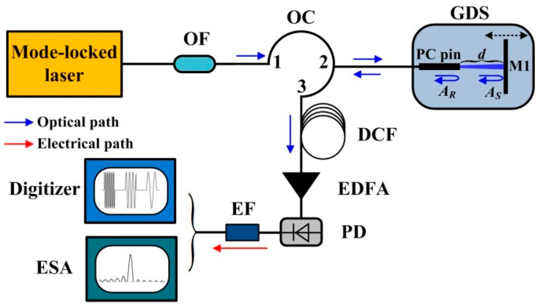
2. Experimental Setup

Figure 1 shows the experimental setup of frequency-tunable pulsed microwave waveform generation, which was achieved by using an unbalanced single-arm interferometer with frequency-to-time mapping. The optical source used in our experiments was a passive mode-locked fiber laser, of which the repetition frequency, pulse width, output power and center wavelength were 22 MHz, 500 fs, 5 mW and 1550 nm, respectively. In addition, the 3 dB spectral linewidth was about 20 nm to ensure that the spectral pattern is approximately flat-topped in the range from 1545 nm to 1555 nm. The optical spectrum of the mode-locked laser was first shaped into a rectangular profile through a bandpass optical filter (OF, 1550 nm ± 5 nm). Then, an unbalanced single-arm interferometer with a frequency-to-time mapping was used and consisted in an optical circulator (OC), a group delay system (GDS), one section of dispersion compensation fiber (DCF, optical fiber type: BD NDCF-G652C), an erbium-doped fiber amplifier (EDFA) and a photodetector (PD). After port 2 of the OC, the pre-shaped femtosecond laser was divided into two parts by the GDS, which consisted of a physical contact ceramic insertion pin (PC pin) and a plane-parallel reflection mirror (M1) mounted on a motorized translation stage. The reflected laser beams, from the end of the PC pin and the M1, were named as AR and AS, respectively. In addition, the group delay time, Δτ, between AR and AS could be adjusted by changing the optical path length difference, d, in the GDS. After port 3 of the OC, the linear dispersion was introduced into the combined laser pulse using the DCF, which realized frequency-to-time mapping. Then, the linear chirped optical pulse train was amplified by the EDFA and then converted into a pulsed microwave waveform by the PD. Moreover, continuous microwave frequency tuning can be obtained by translating the stage to vary the value of d. Finally, the waveform and frequency of the generated pulsed microwave were measured through a bandpass electrical filter (EF, 500 MHz to 40 GHz) by a digitizer and an electrical spectrum analyzer (ESA), respectively.
In this scheme, the frequency-tunable pulsed microwave waveform generation originates from the temporal interferogram that was mapped from the spectral interference through the linear dispersion. The frequency of the temporal interferogram depends on the dispersion value and the group delay time between the two coherent beams in the unbalanced single-arm interferometer. The total dispersion value is usually a constant, while the optical fiber devices are fixed in the system. However, the group delay time can be simply varied without any polarization control. Therefore, the unbalanced single-arm interferometer with a frequency-to-time mapping configuration is considered a suitable frequency-tunable pulsed microwave waveform generator. Figure 2 shows the basic principle of the pulsed microwave frequency tuning.
As shown in Figure 2, owing to the frequency-to-time mapping effect induced by the DCF, the pulses of AR and AS are broadened in the time domain and are described as follows:
{ A i ( t ) = a i ( t ) c o s [ 2 π 0 t f i ( τ ) d τ ] f i ( t ) = t / β 2 L
where f i ( t ) is the instantaneous frequency (i = R or S), in which β2 and L are the group velocity dispersion parameter and length of the DCF, respectively. In addition, a i ( t ) is the envelope of the dispersed pulse in the time domain, which is equal to the Fourier transform result of the spectral amplitude that was determined by the responsivity of the OF. It is worth mentioning that Equation (1) is established only when the femtosecond laser pulse width, tP, and dispersion value meet the Fraunhofer condition of | t P 2 / β 2 L | < < 1 . Therefore, the output microwave signal from the PD is given by [27]:
I ( t ) R e | a S ( t ) | 2 + R e | a R ( t ) | 2 + 2 R e | a S ( t ) | | a R ( t ) | cos { 2 π [ f R ( t ) f S ( t ) ] t }
where Re is the responsivity of the PD. Additionally, A S ( t ) = k A R ( t Δ τ ) , where k is the amplitude ratio of AS to AR. In addition, assuming that the transmission curve of the OF is a standard rectangular profile in the optical frequency domain, and considering that the maximum time delay of the two laser pulse edges was 0.6 ns, which is much less than the stretched laser pulse width of 24 ns, it is considered that the time variation of a i ( t ) hardly affects the result of I(t).Then, Equation (2) was simplified as follows:
I ( t ) R e a R 2 + R e a R 2 V cos [ 2 π ( Δ t / β 2 L ) t ]
where V = 2 k / ( 1 + k 2 ) is the visibility of the temporal interferogram. In addition, the first term on the right-hand side can be filtered by the EF in our experiment. Thus, according to Equation (3), the maximum amplitude of the generated microwave signal depends on the power of the input laser and the responsivity of the PD. The value of V should approximate to 1 in order to make the generated microwave waveform have a good fringe contrast. In our experiment, since the efficiency of the PC pin receiving energy from the reflected laser, AR, was about 0.1%, the PC pin was coated with a 30 dB reflectivity for 1550 nm to balance the signal intensity between AR and AS. Additionally, the frequency of the generated microwave signal, f I = Δ τ / β 2 L , is independent of time but is determined by the parameters of the GDS and DCF. Specifically, the dispersion constant D of the DCF is equal to c β 2 / λ 2 , which is related to the group velocity dispersion parameter β2 and central frequency λ of the femtosecond laser. In this situation, D and L should be considered as constants. In addition, group delay time Δτ ( Δ τ = 2 d / c ) was determined by the optical path length difference, d, in the GDS. Hence, the frequency of the generated microwave signal is further expressed as:
f I = 2 d / D L λ 2
In our experiments, the dispersion constant, relative dispersion slope and length of the DCF were fixed at −190 ps/(nm∙km), 0.0028 nm−1 and 20 km, respectively. According to Equation (4), it is clear that the frequency of the microwave pulse is proportional to the optical path length difference. Therefore, frequency tuning can easily be achieved by adjusting optical path length difference, d, in the GDS. Furthermore, the calculated result of the conversion constant between fI and d is 0.219 GHz/mm, which will be compared with the experimental results below.

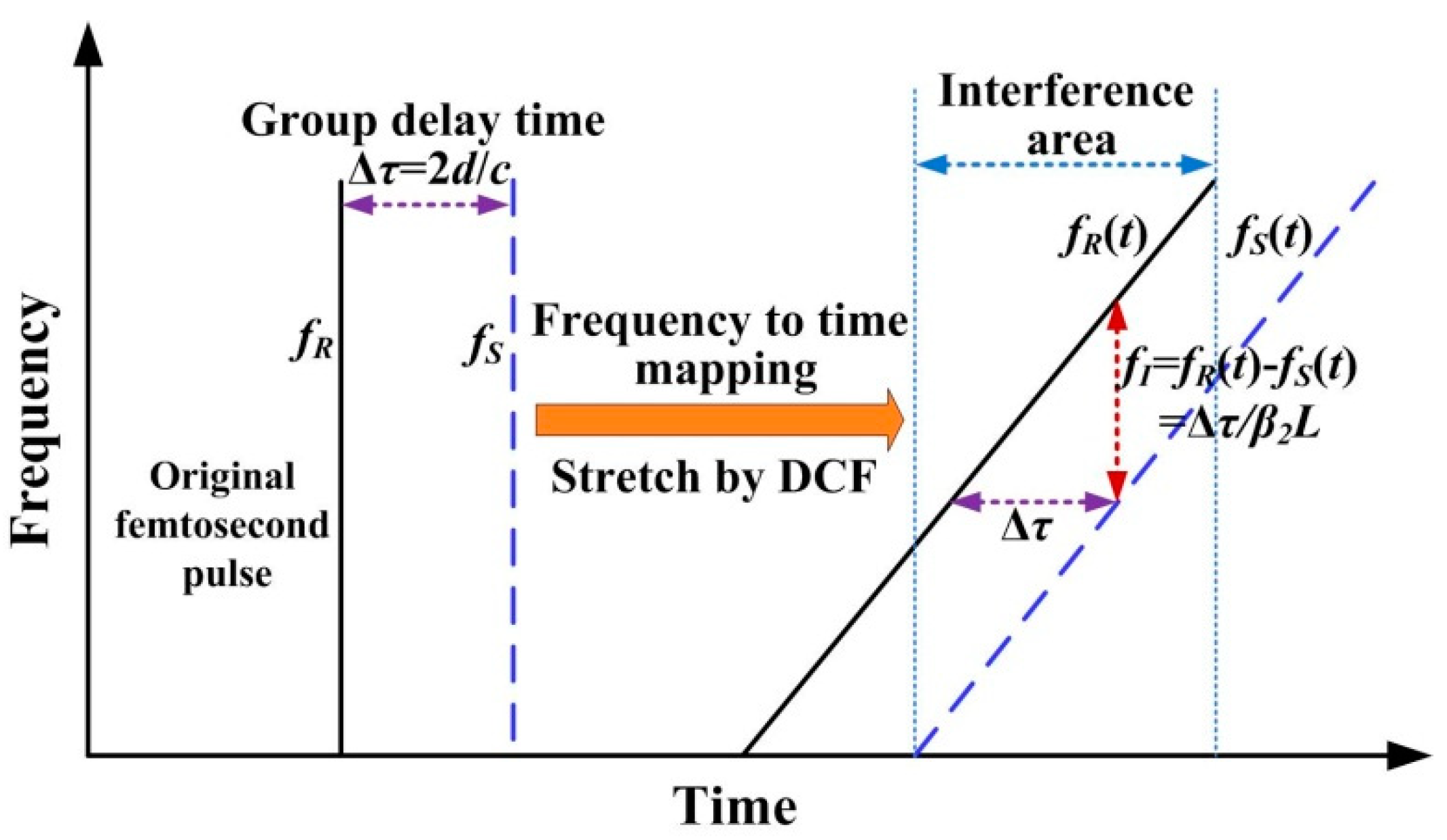
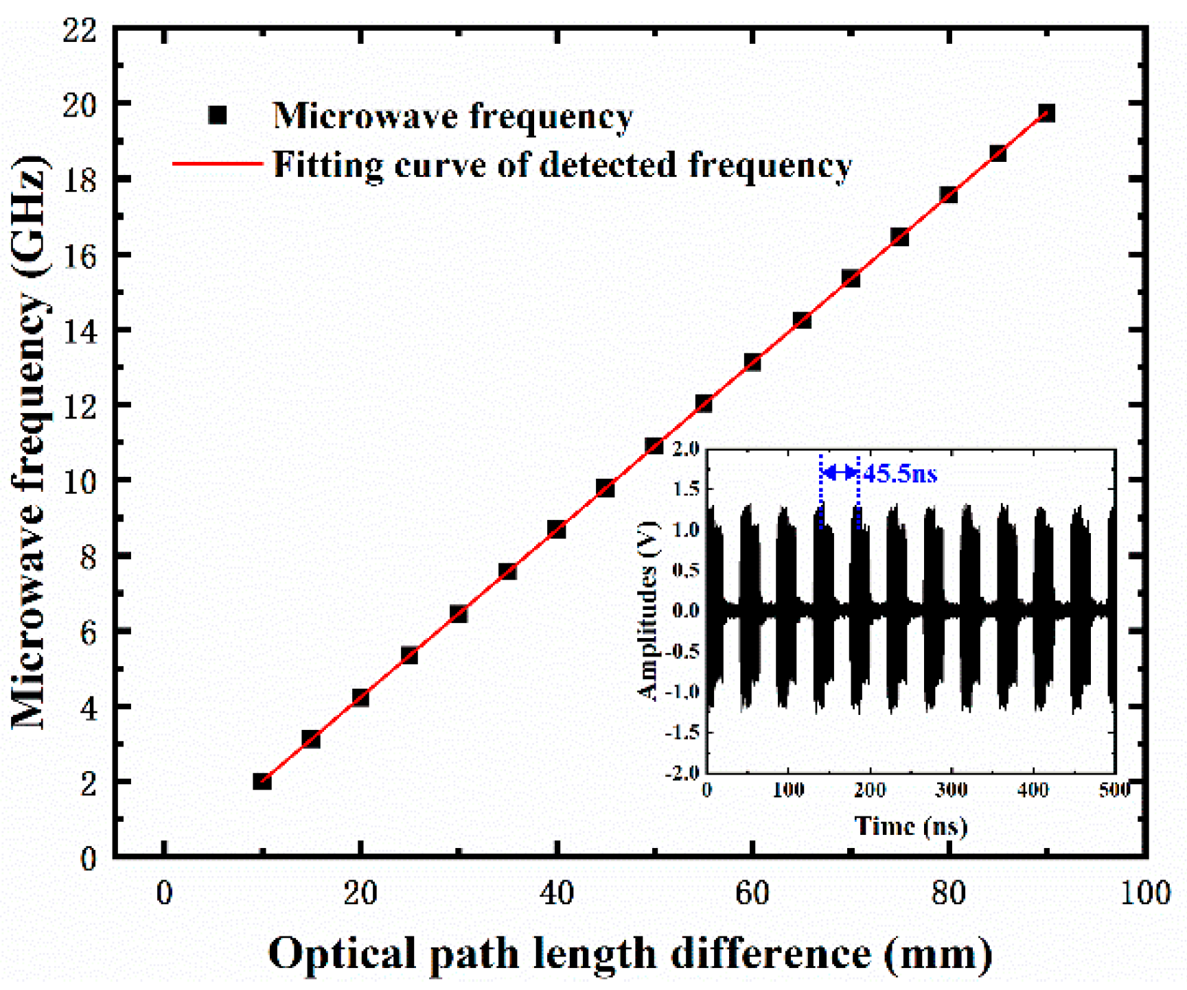
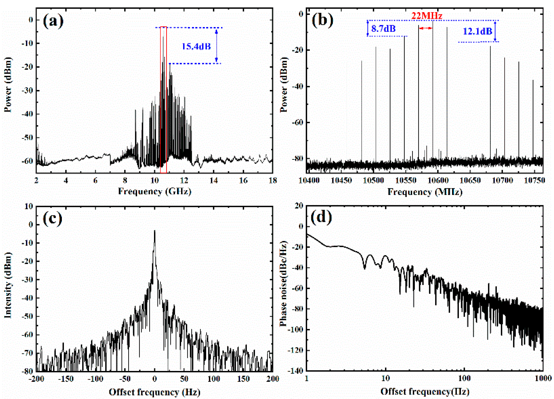
3. Results and Discussion

Figure 3 shows the frequency-tuning characteristics of the generated microwave signals that were detected by the ESA with a resolution bandwidth of 10 Hz. When optical path length difference, d, was varied from 10 mm to 90 mm, the microwave frequency was continuously tuned from 2.0 GHz to 19.7 GHz. As shown by the red line in Figure 3, linear fitting is performed for the experimental data. The measured conversion constant between fI and d equals the slope of the fitting curve, which is 0.22209 GHz/mm. It is clear that the calculated and measured values of the conversion constant are very close. In addition, the goodness of fit (R-square) is 0.99999 in this system. Such a high linearity is attributed to the same optical fiber path for the AR and AS in the interferometer, which could eliminate the nonlinear effects caused by optical devices. Additionally, rapid frequency tuning was achieved by a fast-moving scan of the motorized translation stage in the GDS. The scan speed was 3000 mm/s with repeatability of less than 1 μm, corresponding to a frequency-tuning response time of 0.66627 MHz/μs in our experiment. Moreover, it is deduced that a higher microwave frequency could be obtained by increasing the optical path length difference. However, limited by the frequency response bandwidth of the PD, a higher frequency was not attempted in our experiment. The inset in Figure 3 shows the train of generated microwave pulses, which indicates that the time interval between two contiguous pulses is about 45.5 ns.
Figure 4a shows the measured electrical spectrum of the pulsed microwave signals at 10.6 GHz. It is obvious that the generated microwave signal has a relatively narrow center frequency with broadband noise, of which the signal-to-noise ratio was higher than 15.4 dB. The details of the generated microwave frequency lines, marked with a red box in Figure 4a, are enlarged and shown in Figure 4b. Owing to the high phase stability of the mode-locked laser and the high dispersion linearity of the DCF, these frequency lines have a steady frequency interval of 22 MHz, which could be extracted to generate spectrally pure microwaves via electrical filtering processing [28]. In addition, the maximum power peak of −3.6 dBm was located at 10.592 GHz. Except for the frequency lines at 10.570 GHz and 10.614 GHz, the power difference between 10.592 GHz and the other frequencies was higher than 8.7 dB. Moreover, the linewidth of frequency line at 10.592 GHz was measured by the ESA with a resolution bandwidth of 1 Hz and is shown in Figure 4c. The 3 dB bandwidth of each frequency line was estimated to be less than 2 Hz through Gaussian fitting. Furthermore, based on Equation (2) in [29], the single-sideband phase noise of the 10.592 GHz carrier was calculated. As shown in Figure 4d, the single-sideband phase noise was about −28 dBc/Hz, −69 dBc/Hz and −94 dBc/Hz at the offset frequencies of 10 Hz, 100 Hz and 1000 Hz, respectively. Using our method, since the microwave pulse signal was generated by the beat frequency of two coherent laser signals that were split by the same laser pulse, the noise caused by the initial phase jitter was avoided. Therefore, a slight time jitter of the mode-locked laser will not affect the performance of the proposed experimental setup. The noise of the microwave pulse mainly came from the photodetector noise.
To better characterize the generated microwave waveform, temporal interferograms were detected using a digitizer with an impedance of 50 Ω. Figure 5a,b show the measured microwave pulse waveforms at different frequencies and the details of the red-dotted box, respectively. The peak–peak values of the voltage amplitudes for the microwave waveforms were measured to be about 2.7 V at 5.4 GHz, 2.2 V at 10.9 GHz and 1.8 V at 15.3 GHz, respectively. With an increase in frequency, the voltage amplitudes of microwave signals slowly decreased, which was caused by the decrease in the gain of the PD. In addition, slight amplitudes fluctuations at different frequencies were observed with same trend, which originated from the power spectrum fluctuation of the mode-locked laser. Furthermore, as shown in Figure 2, the microwave pulse duration is mainly determined by the interference area in the time domain. Considering the increased time of the PD and the nonlinear effect of the DCF, the pulse duration is on the order of ten picoseconds to hundreds of nanoseconds and can be designed by controlling the length of the DCF. Owing to the fact that the maximum difference of the pulse duration at different frequencies was only 600 ps, the pulse duration of the microwave waveform was regarded as approximately 24 ns in our experiment.
Furthermore, in order to verify the frequency stability of the generated microwave signals, the pulse trains were measured at different frequencies. Limited by the calculation capabilities of computers, these trains that contained about 220 pulses were analyzed using short-time Fourier transform (STFT) and are shown in Figure 6a. The results showed that a good consistency of microwave frequencies was maintained in each pulse train. Since it is mainly affected by the optical path difference in the unbalanced single-arm interferometer, the frequency stability of the microwave pulse train could be further improved for a long time by enhancing the structural stability of the GDS. Additionally, some special waveforms, such as triangular-, rectangle- and square-shaped, can be decomposed into a series of sine waveforms via Fourier series analysis, which means that the generated microwave pulses with a single frequency should have the ability to synthesize complex waveform pulse. Therefore, the synthesis of a near-triangular-shaped microwave pulse was carried out in our experiment, being achieved by the superpositioning of two sinusoidal pulses with a frequency ratio of 1:3 and an amplitude ratio of 9:1. The temporal waveform of the near-triangular-shaped microwave signal with frequency of about 4.5 GHz is shown in Figure 6b. Through fast Fourier transform (FFT) analysis, the frequency component and power difference were obtained and are shown in Figure 6c. They are consistent with our design parameters. However, it is worth mentioning that a slight distortion of the synthesized signal (in Figure 6b), caused by the multiple frequency lines near 4.5 GHz and 13.5 GHz, was discovered. This kind of distortion could be eliminated by using an electrical bandpass filter to extract the single frequency line as a spectrally pure microwave, which we will implement in future research.

4. Conclusions

In conclusion, a compact and easy-to-operate method of generating frequency-tunable microwave pulses based on a femtosecond laser-excited unbalanced single-arm interferometer with frequency-to-time mapping has been demonstrated. Through simple spatial–optical group delay adjustment, the frequency of the pulsed microwave waveform was continuously tuned from 2.0 GHz to 19.7 GHz with high tuning linearity. Additionally, the pulse duration of the microwave waveform was measured to be 24 ns. Moreover, thanks to the designs of the single-arm optical path and the polarization-independent interference, the environmental disturbance and nonlinear effects caused by the optical devices were eliminated, which ensured that the microwave pulse train generated from this system had good stability in terms of frequency and electrical amplitude. Furthermore, a near-triangular-shaped microwave pulse at 4.5 GHz was synthesized by two sinusoidal signals generated by this system, which showed the potential to realize the generation of special microwave waveform pulses. In future research, phase tuning or phase encoding will be implemented by adding phase modulation between the PC pin and reflection mirror, based on the proposed scheme, to further improve the applicability of this system.

Author Contributions

Conceptualization, L.T. and J.W. (Jidong Weng).; methodology, S.L.; validation, X.J. and T.T.; formal analysis, H.M.; resources, X.W.; data curation, L.C.; writing—original draft preparation, X.J. and L.T.; writing—review and editing, L.Z. and C.L.; visualization, J.W. (Jian Wu); supervision, J.W. (Jidong Weng); funding acquisition, X.J., L.T. and J.W. (Jidong Weng). All authors have read and agreed to the published version of the manuscript.

Funding

This research was funded by the National Natural Science Foundation of China (grant number: 62101518), the Foundation of National Key Laboratory of Shock Wave and Detonation Physics (grant number: JCKYS2019212004, JCKYS2019212005) and the Project supported by presidential Foundation of CAEP (grant number: PY20210006, CX2019003).

Institutional Review Board Statement

Not applicable.

Informed Consent Statement

Not applicable.

Data Availability Statement

Not applicable.

Conflicts of Interest

The authors declare no conflict of interest.

References

  1. Capmany, J.; Novak, D. Microwave photonics combines two worlds. Nat. Photonics 2007, 1, 319–330. [Google Scholar] [CrossRef]
  2. Yao, J. Microwave photonics. J. Light. Technol. 2009, 27, 314–335. [Google Scholar] [CrossRef]
  3. Pan, S.; Zhang, Y. Microwave photonic radars. J. Light. Technol. 2020, 38, 5450–5484. [Google Scholar] [CrossRef]
  4. Biggsa, D.R.; Cappelli, M.A. Tunable microwave pulse generation using discharge plasmas. Appl. Phys. Lett. 2016, 109, 124103. [Google Scholar] [CrossRef]
  5. Amari, S.E.; Kenaan, M.; Merla, C.; Arnaud-Cormos, D.; Leveque, P.; Couderc, V. Microwave subnanosecond pulse generation and shaping by using infrared optoelectronic switching. In Proceedings of the International Power Modulator and High Voltage Conference, Atlanta, GA, USA, 23–27 May 2010. [Google Scholar]
  6. Song, C.; Zheng, Z.; Lei, M.; Qian, J.; Gao, X.; Huang, S. Photonics Generation of Pulsed Arbitrary-Phase-Coded Microwave Signals Based on the Conversion Between Intensity Modulation and Phase Modulation. J. Light. Technol. 2020, 38, 1243–1249. [Google Scholar] [CrossRef]
  7. Bernhardi, E.H.; Khan, R.; Roeloffzen, C.; Wolferen, H.; Wörhoff, K.; Ridder, R.M.; Pollnau, M. Photonic generation of stable microwave signals from a dual-wavelength Al2O3:Yb3+ distributed-feedback waveguide laser. Opt. Lett. 2012, 37, 181–183. [Google Scholar] [CrossRef] [Green Version]
  8. Gao, Y.; Wen, A.; Zheng, H.; Liang, D.; Lin, L. Photonic microwave waveform generation based on phase modulation and tunable dispersion. Opt. Express 2016, 24, 12524–12533. [Google Scholar] [CrossRef]
  9. Chen, G.; Huang, D.; Zhang, X.; Cao, H. Photonic generation of a microwave signal by incorporating a delay interferometer and a saturable absorber. Opt. Lett. 2008, 33, 554–556. [Google Scholar] [CrossRef]
  10. Liu, J.; Huang, C.; Shu, C. Photonically assisted microwave waveform generation by gain-transparent SBS-induced carrier processing. Opt. Lett. 2017, 42, 3852–3855. [Google Scholar] [CrossRef] [PubMed]
  11. He, Y.; Jiang, Y.; Zi, Y.; Bai, G.; Tian, J.; Xia, Y.; Zhang, X.; Dong, R.; Luo, H. Photonic microwave waveforms generation based on two cascaded single-drive Mach-Zehnder modulators. Opt. Express 2018, 26, 7829–7841. [Google Scholar] [CrossRef]
  12. Jiang, H.Y.; Yan, L.S.; Ye, J.; Pan, W.; Luo, B.; Zou, X. Photonic generation of phase-coded microwave signals with tunable carrier frequency. Opt. Lett. 2013, 38, 1361–1363. [Google Scholar] [CrossRef] [PubMed]
  13. Xia, Y.; Jiang, Y.; Zi, Y.; He, Y.; Tian, J.; Zhang, X.; Luo, H.; Dong, R. Photonic microwave waveforms generation based on pulse carving and superposition in time-domain. Opt. Commun. 2018, 414, 177–184. [Google Scholar] [CrossRef]
  14. Jiang, H.Y.; Yan, L.S.; Sun, Y.F.; Ye, J.; Pan, W.; Luo, B.; Zou, X.H. Photonic arbitrary waveform generation based on crossed frequency to time mapping. Opt. Express 2013, 21, 6488–6496. [Google Scholar] [CrossRef]
  15. Kumar, R.; Raghuwanshi, S.K. Photonic generation of a parabolic-shaped microwave signal and dual-linear-chirp microwave waveform. Appl. Opt. 2020, 59, 6024–6029. [Google Scholar] [CrossRef] [PubMed]
  16. Chou, J.; Han, Y.; Jalali, B. Adaptive RF-photonic arbitrary waveform generator. IEEE Photonics Technol. Lett. 2003, 15, 581–583. [Google Scholar] [CrossRef]
  17. Liu, J.; Lucas, E.; Raja, A.S.; He, J.; Riemensberger, J.; Wang, R.N.; Karpov, M.; Guo, H.n.; Bouchand, R.; Kippenberg, T.J. Photonic microwave generation in the X- and K-band using integrated soliton microcombs. Nat. Photonics 2020, 14, 486–491. [Google Scholar] [CrossRef]
  18. Ma, C.; Yu, J.; Wang, J.; Yu, Y.; Xie, T.; Yang, E.; Jiang, Y. Photonic generation of microwave waveforms based on a dual-loop optoelectronic oscillator. Opt. Commun. 2018, 426, 158–163. [Google Scholar] [CrossRef]
  19. Liu, S.; Wu, K.; Zhou, L.; Lu, L.; Zhang, B.; Zhou, G.; Chen, J. Microwave Pulse Generation with a Silicon Dual-Parallel Modulator. J. Lightwave Technol. 2020, 38, 2134–2143. [Google Scholar] [CrossRef]
  20. Zhang, F.; Ge, X.; Pan, S.; Yao, J. Photonic generation of pulsed microwave signals with tunable frequency and phase based on spectral-shaping and frequency-to-time mapping. Opt. Lett. 2013, 38, 4256–4259. [Google Scholar] [CrossRef] [Green Version]
  21. Li, W.; Wang, W.Y.; Wang, W.T.; Liu, J.G.; Zhu, N.H. Photonic Generation of Microwave Pulse Using a Phase-Modulator-Based Sagnac Interferometer and Wavelength-to-Time Mapping. IEEE Photonics J. 2014, 6, 1–8. [Google Scholar] [CrossRef]
  22. Zhang, F.; Ge, X.; Pan, S. Background-free pulsed microwave signal generation based on spectral shaping and frequency-to-time mapping. Photon. Res. 2014, 2, B5–B10. [Google Scholar] [CrossRef]
  23. Chi, H.; Zeng, F.; Yao, J. Photonic Generation of Microwave Signals Based on Pulse Shaping. IEEE Photonic. Technol. Lett. 2007, 19, 668–670. [Google Scholar] [CrossRef]
  24. Ye, J.; Yan, L.; Pan, W.; Luo, B.; Zou, X.; Yi, A.; Yao, S. Two-dimensionally tunable microwave signal generation based on optical frequency-to-time conversion. Opt. Lett. 2010, 35, 2606–2608. [Google Scholar] [CrossRef]
  25. Ye, J.; Yan, L.; Pan, W.; Luo, B.; Zou, X.; Yi, A.; Yao, S. Photonic generation of triangular-shaped pulses based on frequency-to-time conversion. Opt. Lett. 2011, 36, 1458–1460. [Google Scholar] [CrossRef] [PubMed]
  26. Wang, W.; Liu, J.; Mei, H.; Sun, W.; Wang, W.; Yuan, H.; Zhu, N. Photonic Generation of Pulsed Microwave Signal Based on Phase Shifted Lyot Optical Filter. IEEE Photonic. Technol. Lett. 2015, 27, 1845–1848. [Google Scholar] [CrossRef]
  27. Xia, H.; Zhang, C. Ultrafast and Doppler-free femtosecond optical ranging based on dispersive frequency-modulated interferometry. Opt. Express 2010, 18, 4118–4129. [Google Scholar] [CrossRef] [PubMed] [Green Version]
  28. Dai, Y.; Cen, Q.; Wang, L.; Zhou, Y.; Yin, F.; Dai, J.; Li, J.; Xu, K. Low phase noise microwave extraction from femtosecond laser by frequency conversion pair and IF-domain processing. Opt. Express 2015, 23, 31936–31944. [Google Scholar] [CrossRef] [PubMed]
  29. Zhan, Z. How to use a spectrum analyzer to measure phase noise of digital signal generator. In Proceedings of the Asia-Pacific Radio Science Conference, Qingdao, China, 24–27 August 2004. [Google Scholar]
Figure 1. Experimental setup of frequency-tunable pulsed microwave waveform generation. OF, bandpass optical filter; OC, optical circulator; GDS, group delay system; PC pin, physical contact ceramic insertion pin; M1, plane-parallel reflection mirror; DCF, dispersion compensation fiber; EDFA, erbium-doped fiber amplifier; PD, photodetector; EF, bandpass electrical filter; ESA, electrical spectrum analyzer.
Applsci 11 11928 g001
Figure 2. The principle of pulsed microwave frequency tuning based on an unbalanced single-arm interferometer with frequency-to-time mapping.
Applsci 11 11928 g002
Figure 3. The frequency-tuning characteristics of the generated microwave signals. Inset: the train of generated microwave pulses.
Applsci 11 11928 g003
Figure 4. (a) The measured electrical spectrum of pulsed microwave signal at 10.6 GHz. (b) A partial enlargement. (c) The linewidth and (d) the single-sideband phase noise of microwave frequency line at 10.592 GHz.
Applsci 11 11928 g004
Figure 5. (a) The overall waveforms of measured microwave pulse at different microwave frequencies. (b) A partial enlargement.
Applsci 11 11928 g005
Figure 6. (a) STFT analysis of the measured microwave pulse train at different frequencies. (b) The temporal waveform and (c) FFT analysis of the near-triangular-shaped microwave pulse signal.
Applsci 11 11928 g006
Publisher’s Note: MDPI stays neutral with regard to jurisdictional claims in published maps and institutional affiliations.

