
Characteristics of Collimators Based on the Large-Mode-Area CMCF for Coupling Laser Beam


1
School of Information Engineering, Minzu University of China, Beijing 100081, China
2
Center for Advanced Laser Technology, Hebei University of Technology, Tianjin 300401, China
*
Author to whom correspondence should be addressed.
Appl. Sci. 2021, 11(24), 11604; https://doi.org/10.3390/app112411604
Submission received: 26 October 2021
/
Revised: 22 November 2021
/
Accepted: 3 December 2021
/
Published: 7 December 2021
(This article belongs to the Special Issue Laser Technologies and Nonlinear Optics in Surface Sciences)
Abstract
:A new collimator based on a homemade concentric multilayer-core fiber (CMCF) is proposed and experimentally demonstrated. This collimator was fabricated using a tail fiber with large mode area and single-mode operation. By exploiting the optical transmission matrix, the propagation characteristic and coupling mechanism of this CMCF-based collimator was introduced meticulously. The coupling losses of the laser beam using this collimator in the off-axis, angular, and axial deviations were analyzed separately. In order to determine the relationship between the geometric redundancy of this collimator and the effective mode field area of the tail fiber, the corresponding mathematical model was established. Through model calculation and experiment measurement, the coupling properties of the collimator were improved effectively. Compared with the common SMF-based collimator, the declination redundancy of the CMCF-based one improved by 20%, which could make the coupling of the optical fiber collimator easier. Therefore, this collimator has potential application value in the laser diode coupling unit and high-speed optical communication system.
1. Introduction
With the development of high-speed optical communication, optical fiber collimators have been used for a wide variety of applications, not only in optical transmission systems but also in coupled laser systems and other fields as important optical passive devices [1,2,3,4]. There are two main modalities for fiber connections, one is arc fusion splicing using a fiber fusion splicer and the other is free-space fiber–fiber coupling using collimators. The first connection method is often used in laboratories or engineering practices where changes are not desirable because of its high reliability and low connection loss; the second connection method is commonly used in experimental research or free-space optical communication because of its flexible and detachable characteristics [5]. Fiber collimators have been widely used in various fields, especially for the scene of movable connection, such as spatial coupling of the laser [6,7,8,9], integrated fiber-optic devices [10], and so on.
As the numerical aperture of ordinary optical fiber is relatively small, it is difficult to achieve the direct free-space alignment of the laser beam between the two fibers. Under this circumstance, the coupling loss is very high. Compared to fiber-to-fiber coupling, the fiber collimators allow a larger gap between the fibers and make the system less sensitive to axial and off-axis deviations [11]. Hence, a Gaussian beam would be easily expanded and collimated by optical fiber collimators to achieve high coupling efficiency. It can also couple the collimated light into the fiber with very small losses and is widely used in optical switching, optical signal processing, laser alignment, optical measurement, and other systems [2,12,13,14,15]. For instance, in free-space optical communication, the coupling loss of a collimated laser becomes one of the key performance indicators. Therefore, one of the core devices in a laser alignment system is the optical fiber collimator. There is a problem that the process could generate waste easily if the alignment is not performed by well-trained personnel. Only by professionally trained personnel carefully adjusting the relative position and angle between the two collimators can coupling loss be minimized. Since the whole process is performed manually, the production efficiency is low, and the consistency of products is poor. Highly-skilled operators are required in product assembly, but even so, the quality could still be unstable. Thus, there is an urgent need to improve the anti-deviation capability during fiber collimator coupling. How to improve the coupling efficiency and reduce the coupling loss of the fiber collimator has become a research hotspot in optical communication [16,17,18,19,20].
Until now, several new methods have been introduced to design fiber collimators for the coupling efficiency improvement. Hu et al. proposed a new tapered fiber collimator whose coupling efficiency was higher for the same lateral deviation compared with the traditional connector [21]. A beam-expanded fiber collimator was designed and manufactured by Dong et al. [22]. With their contribution, the coupling performance was enhanced, and the collimator adjustment was simplified. Wakabayashi et al. designed a graded-index type photonic crystal fiber (GI-PCF) collimator, which obtained high optical coupling efficiency and good tolerance in fiber length error compared with the GI-type multimode collimator [23]. A collimator with a large-mode-area tail fiber was designed and demonstrated by Unger et al. [24]. The coupling system based on this collimator with large-mode-area tail fiber was clarified by a theoretical analysis. In addition, the coupling efficiency was studied by means of experiments with a laser power of about 100 W and then greatly improved.
In this paper, the coupling loss caused by the alignment tolerances of fiber collimators is analyzed. A homemade single-mode collimator based on the large-mode-area concentric multilayer-core fiber (CMCF) is demonstrated, which could effectively improve the coupling loss. The theory and experimental measurements for the CMCF-based collimator are introduced, and some alignment processes are discussed and compared. This testing system was set up using an excitation laser as a light source and a pair of homemade collimators, and the coupling loss introduced by the angular deviation was calculated theoretically and measured experimentally. Satisfactory results were obtained through calculation and experiments, which improved the coupling efficiency by 20%, and thus significantly increased the stability of the optics coupling system.
2. Theoretical Analysis of the Coupling Loss Mechanism
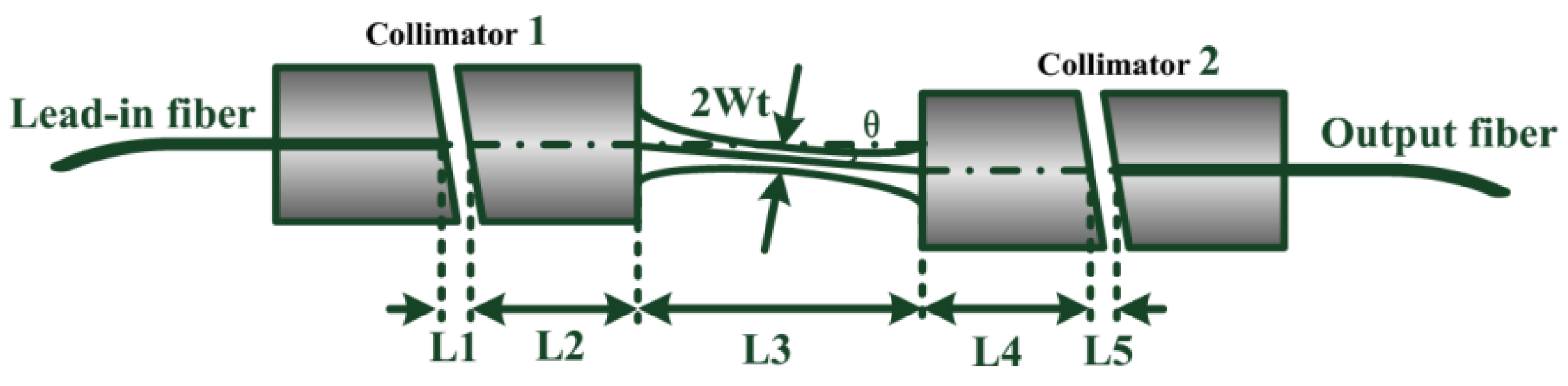
The fiber collimator is a basic optical device in fiber optic communication systems and optical fiber sensing systems, which consists of 1/4 pitch self-focusing lens and single-mode fiber. Its purpose is to collimate the Gaussian beam so as to improve the coupling efficiency between the fibers. The injected light becomes a parallel beam after passing through the self-focusing lens, which is then coupled into the other self-focusing lens. Through the self-focusing lens, the parallel beam is coupled into the output fiber. In this way, the coupling efficiency between the fibers is greatly improved. However, the self-focusing lens does not eliminate the coupling loss caused by the assembly errors. There is a long space between the two fiber collimators, which allows the insertion of optical elements. The fiber collimator consists of a tail fiber and a self-focusing lens, and its structure and coupling are shown in Figure 1.
As shown in Figure 1, Wt is the beam waist radius of the Gaussian beam exiting from the fiber collimator under the case of ideal coupling; L5/L1 are the gap distance between the incident/exiting fibers and the self-focusing lens; L2/L4 are the self-focusing lens lengths, which are less than 1/4 pitch; L3 is the coupling distance, which is ideally twice the distance from the collimator end-face to the beam waist position of the exiting beam.
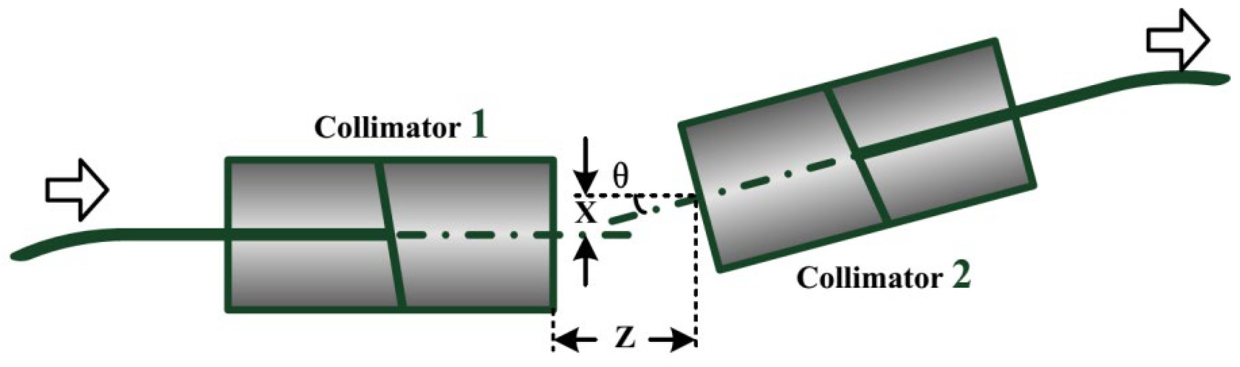
Three types of alignment tolerance are introduced: off-axis deviation X, angular deviation θ, and axial deviation Z, as shown in Figure 2. The system coupling losses introduced by these deviations are not negligible. Therefore, it is important to reduce the coupling loss introduced by the assembly error to improve the stability of the coupling system.
The coupling process between the two collimators was first analyzed and then expressed with the transfer matrix [25]. According to the characteristic of Gaussian beam, the transfer matrix of the collimator coupling is established, which consists of five parts, as follows: the matrix of the gap between the tail fiber in Collimator 1 and the self-focusing lens, T1; the matrix of the self-focusing lens in Collimator 1, T2; the matrix of the working distance between the two collimators, T3; the matrix of the self-focusing lens in Collimator 2, T4; and the matrix of the gap between the tail fiber and the self-focusing lens in Collimator 2, T5. Therefore, the total transfer matrix T of the collimator-based coupling can be obtained as shown in Equation (1).
where is the focusing constant of the self-focusing lens, and n0 is the refractive index in the center of the self-focusing lens. The process of optical coupling is clearly described in Equation (1), in which the beam at any position in the collimator can be found easily.
Usually, the incident beam can be represented by a Gaussian beam. According to the mode coupling theory, the energy-coupling efficiency η can be expressed by Equation (2), which is caused by the mode–field mismatching.
where E1 and E2, respectively, represent the electric field of the exiting and incident beams, and x and y are horizontal and vertical coordinates anywhere on the cross section of collimators, respectively. The coupling of the beams in the collimator can be calculated by (2). In addition, the coupling loss introduced by the deviation factors can be obtained by the transfer matrix together with the coupling efficiency equation.
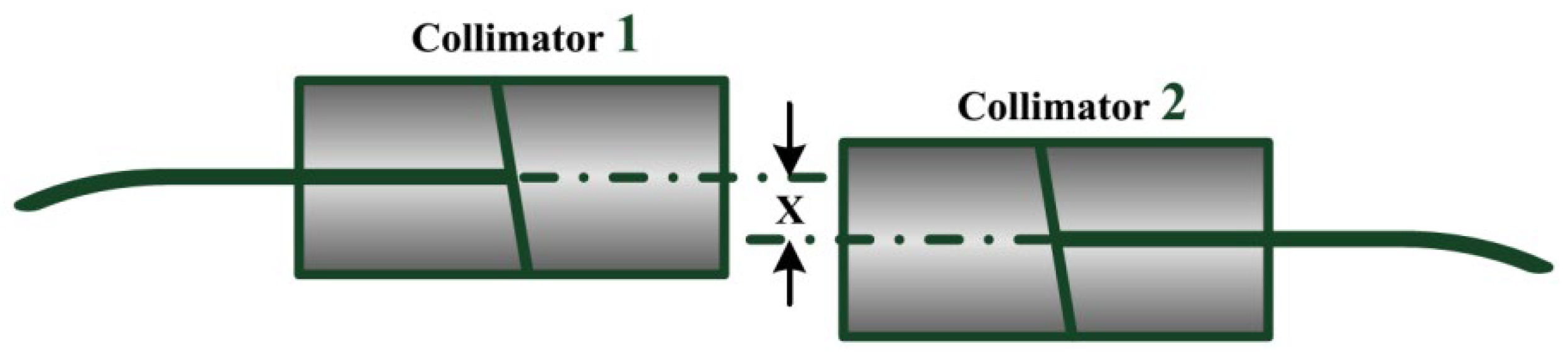
2.1. Off-Axis Deviation
Figure 3 shows the collimator coupling only with off-axis deviation. Usually, the guided mode in the collimator is a Gaussian beam, whose two-dimensional model is shown in Equation (3) [26,27].
where E is the electric field distribution of the beam, and ω is the spot size of the Gaussian mode field at the collimator endface. At the operating wavelength λ, ω could be obtained from the mode field radius ω0 of the tail fiber by the following equation [25,28]
where is the mode field diameter of the tail fiber in both collimators.
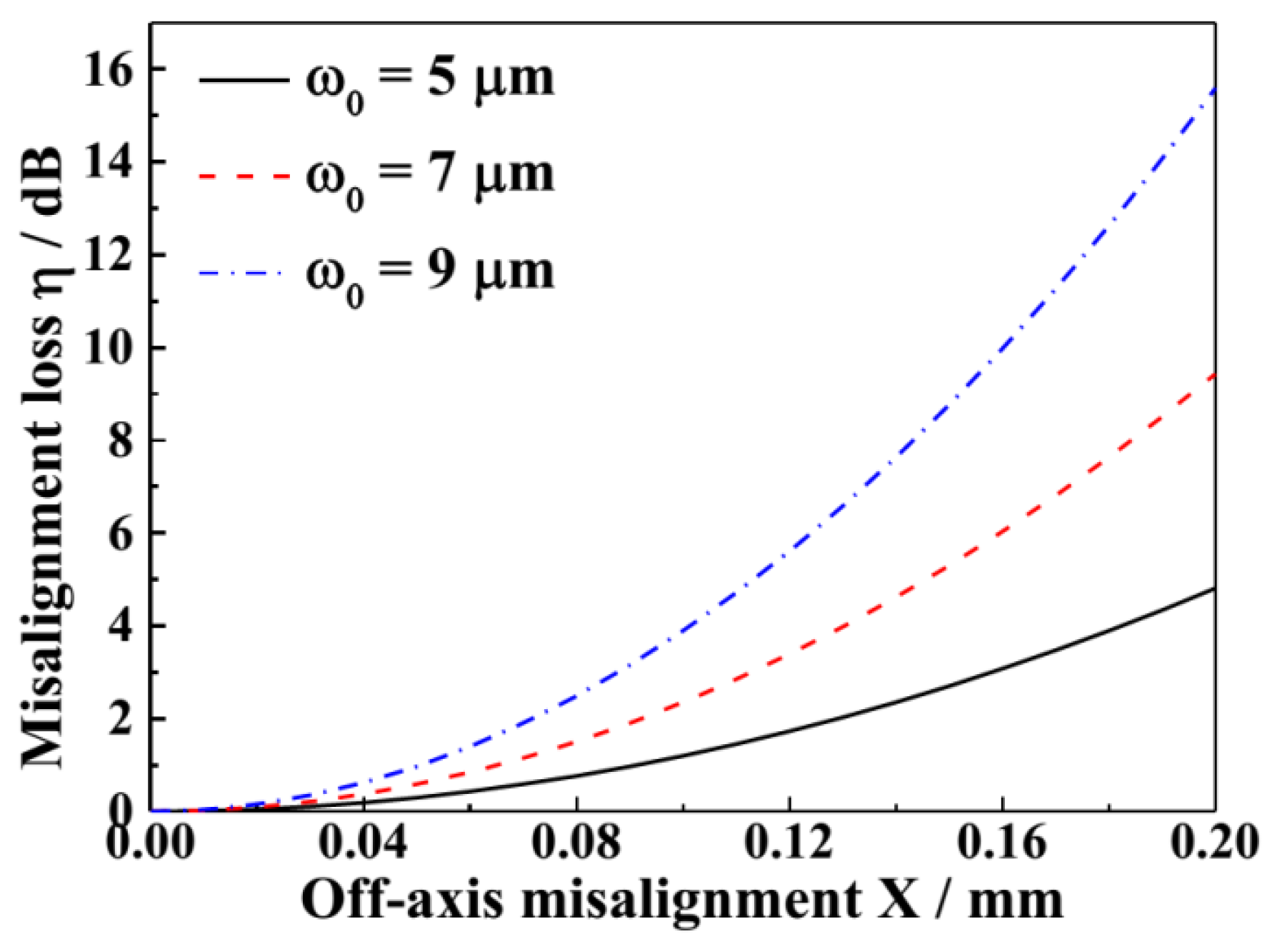
The electric field distribution of the transmitted beam is substituted into Equation (2) when there is only off-axis deviation X. The coupling loss caused by the off-axis deviation is calculated as shown in Equation (5). As λ = 1550 nm, = 0.326, and n0 = 1.5946, the relationship between the off-axis deviation and coupling loss for different ω0 is shown in Figure 4. The coupling loss increases as the off-axis deviation enlarges; meanwhile, the larger the mode field diameter of the tail fiber is, the higher the coupling loss under the same off-axis deviation is.
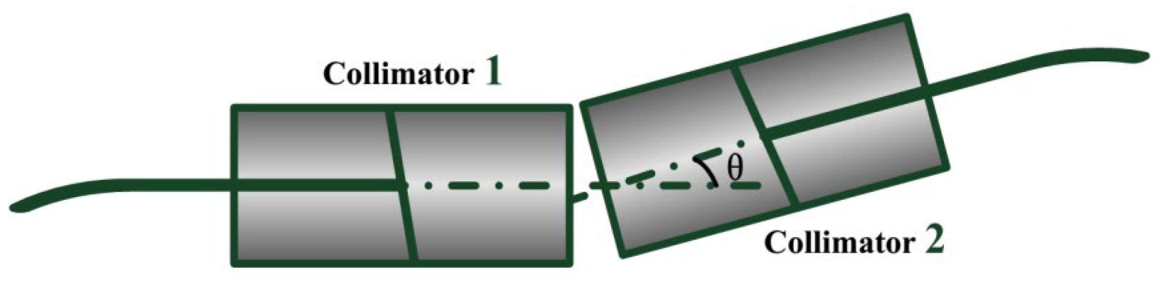
2.2. Angular Deviation
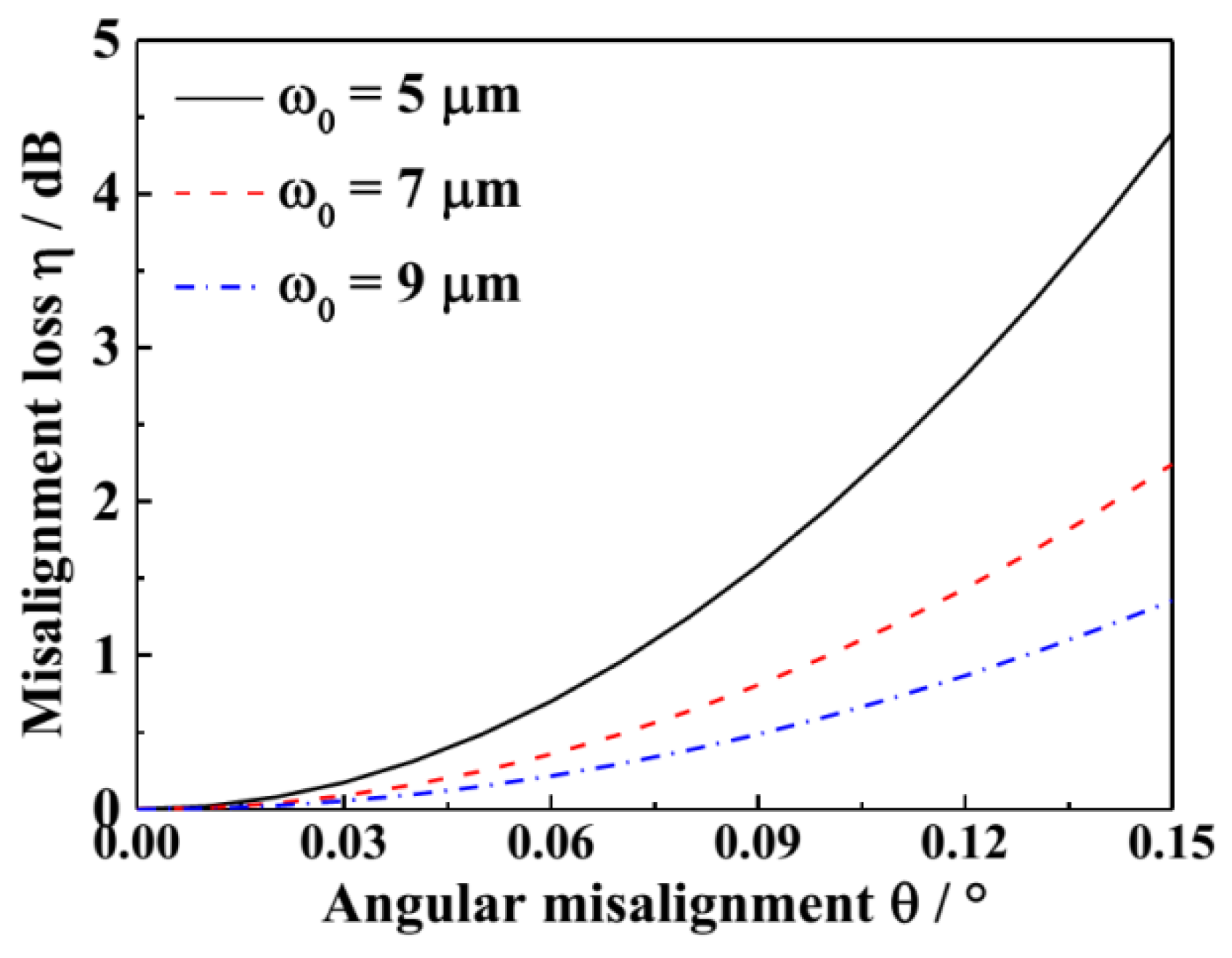
Figure 5 shows the collimator coupling with only angular deviation. When λ = 1550 nm, = 0.326, and n0 = 1.5946, the angular deviation is converted into off-axis deviation by the transfer matrix, and the coupling loss would be obtained, which is shown in Equation (6). The relationship between the angular deviation and coupling loss under different ω0 is shown in Figure 6. The coupling loss increases as the angular deviation enlarges; meanwhile, the larger the mode field diameter of the tail fiber is, the lower the loss of off-axis deviation under the same angular tolerance is [29].
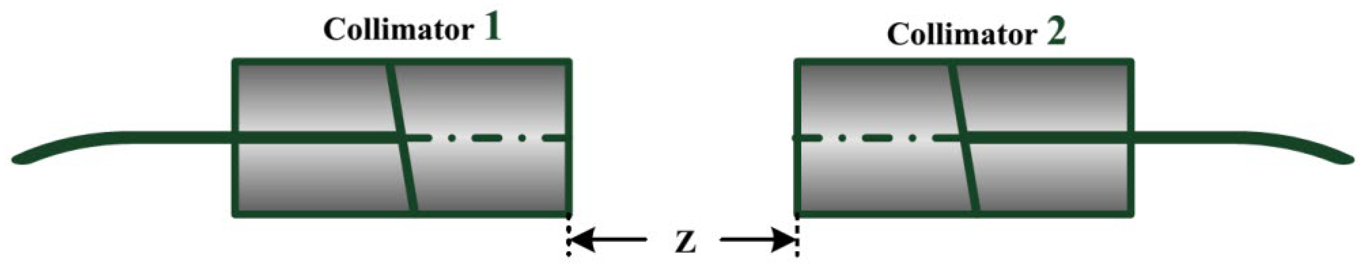
2.3. Axial Deviation
Figure 7 shows the schematic diagram of the axial deviation when the collimator is aligned. Usually, when Gaussian beams are transmitted in the same medium, the electric field magnitude distribution decreases smoothly from the center to the periphery in the axial deviation of the Gaussian curve. Equation (7) is the coupling efficiency η when the radius of the spots at the end face of the two collimators is different from the beam waist radius.
where ω1 is the spot radius at the end of the collimator, and ω1′ is the one after Z, whose relationship is shown in Equation (8); R0 and R0′ are the initial radius of the beam wavefront and the one after Z. When R0 = ∞, R0′ could be expressed by Equation (9).
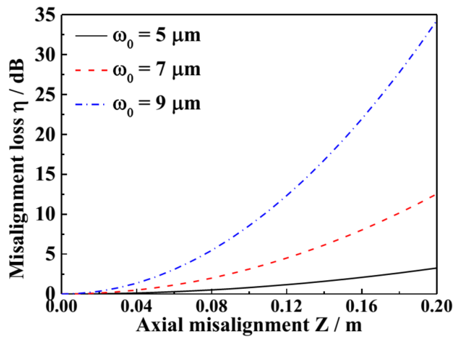
Substituting Equations (4), (8) and (9) into Equation (7), when λ = 1550 nm, = 0.326, and n0 = 1.5946, the coupling loss due to axial deviation is obtained as shown in Equation (10). Figure 8 shows the relationship between the axial deviation and coupling loss when ω0 is different. The larger the mode field diameter of the tail fiber, the higher the axial deviation loss under the same axial tolerance is.
3. Experiments and Discussion
3.1. Design and Fabrication of the Large-Mode-Area CMCF
According to the detailed analysis of the alignment deviations, enlarging the mode field diameter of its tail fiber could reduce the coupling loss caused by angular deviation, while off-axis and axial deviation losses would become higher. As shown in Figure 4, Figure 6 and Figure 8, when the coupling loss between collimators was below 2 dB, the off-axis deviation could have a maximum of 70 μm, the angular deviation could have a maximum of 0.09°, and the axial deviation could have a maximum of 5 cm. Obviously, the adjustable range in off-axis or axial would supply a loosely-coupled application for the alignment between two collimators, and the one in angular is so narrow that the collimator alignment would meet with some difficulty. From the above analysis, the coupling loss between collimators was comparatively more sensitive to angular deviation, and more tolerant to off-axis and axial deviation. Therefore, a large-mode-area fiber could effectively reduce the requirement of alignment angle, decrease the coupling difficulty, and significantly improve the coupling stability of the fiber collimator. Therefore, the design of a single-mode fiber with a large mode area becomes the key to fabricating a new fiber collimator.
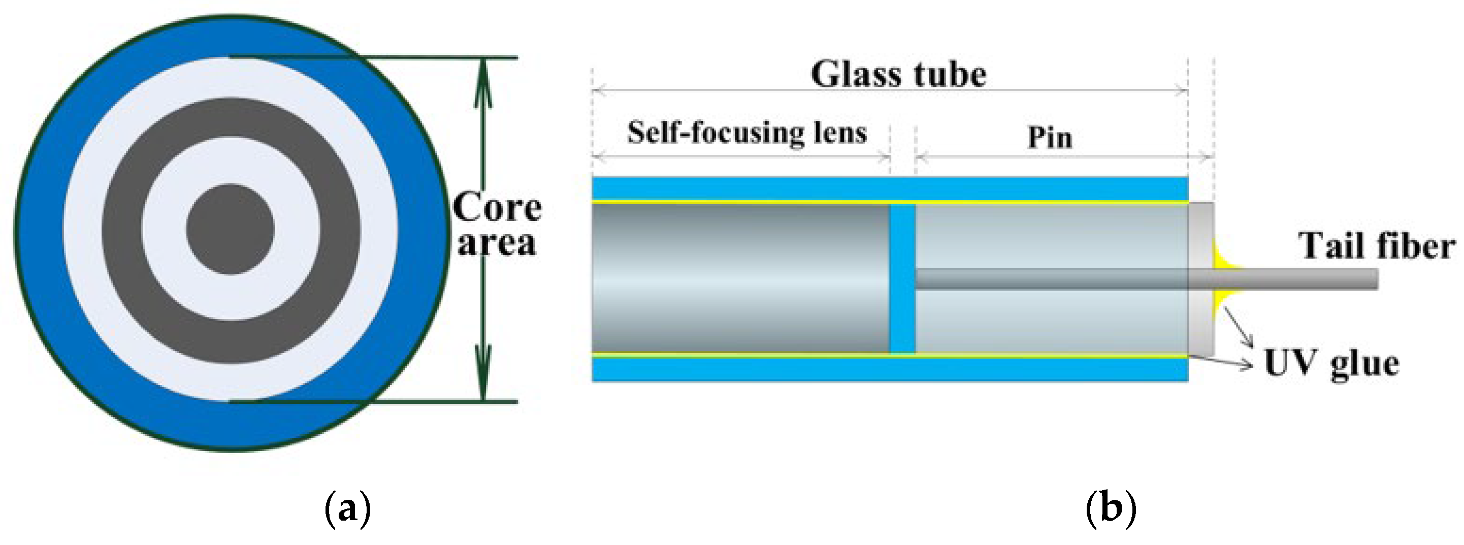
The effective mode area of CMCFs could be greatly enhanced by the concentric multilayer-core structure, which is shown in Figure 9a. However, this structure will increase the number of guided modes, and the CMCF could be designed by proper structural parameters to keep the single-mode operation in the C-band. The CMCF preform was manufactured by modified chemical vapor deposition with in-line solution-doping technology. The entire fabricating process was carried out in a super-clean laboratory in order to obtain high performance optical fibers with high-purity quartz tubes (Heraeus Instruments, Germany). Firstly, the tube was washed and polished with deionized water; then a mixture of silicon tetrachloride and oxygen was added into the base tube and heated to 1700 °C in a graphite furnace for deposition; subsequently, the fluorine-doped layer and germanium-doped layer in the core area were deposited alternately in two cycles to form a concentric multilayer-core structure; the final process was water removal, collapse, and polishing to complete the production of FMF preforms. After the fabrication of the preforms, the lab-made special fiber drawing tower (TGL-8S-A) was used to draw and coat the fibers, and the fibers were drawn into standard fibers with a 125 μm outer diameter.
This homemade large-mode-area EMCF was applied to designing a new type of collimator. The structure of this collimator is depicted in Figure 9b. It consisted of three parts: a self-focusing lens, a pin with a tail fiber, and a glass tube. The CMCF as the tail fiber was fixed in the middle of the pin using UV glue. These three parts were assembled manually with the help of precision translation stages, which adjusted their positions on several spatial dimensions. Firstly, the self-focusing lens and pin with a CMCF were respectively fixed to different translation stages using special clamps. Secondly, the lens and pin were assembled into a close-fitting glass tube. Thirdly, the assembly collimator and a standard one were aligned. Then, an LED light source and optical power meter were respectively connected to the tail fibers. Finally, by monitoring the optical power, the position of the three parts was held constant as the connecting losses were minimal. Finally, a CMCF-based collimator with single-mode operation was produced.
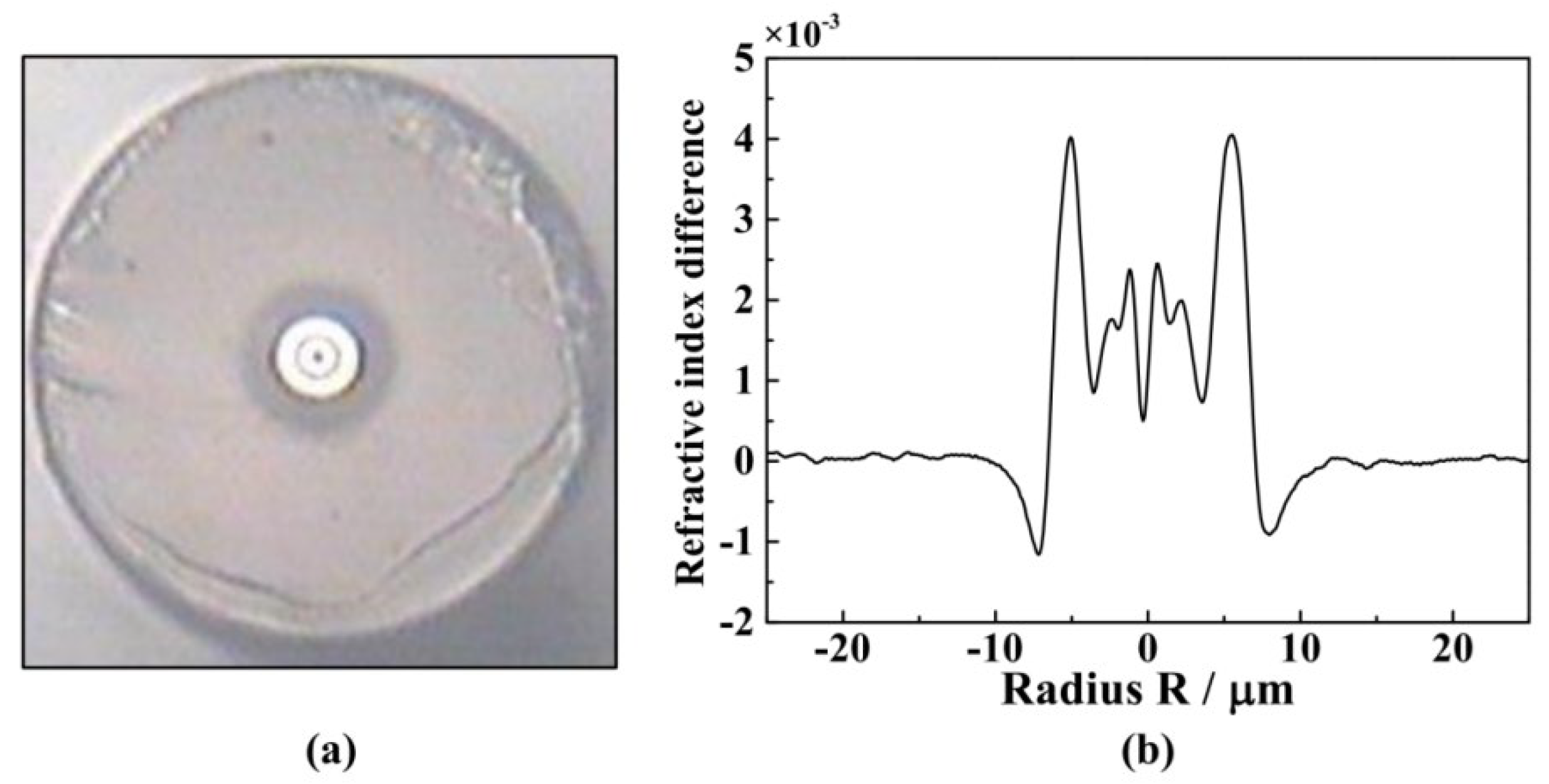
A single-mode CMCF with a large mode area was fabricated by proper design of the structural parameters, and the micrograph of the CMCF and the corresponding refractive index distribution are shown in Figure 10. Figure 10a shows the fiber structure, where the white shiny part of the core represents the high refractive index layer, which was doped with germanide to enhance the refractive index; the black dark part of the core represents the low refractive index layer, which was doped with fluoride to reduce the refractive index; the gray part is the fiber cladding, which was composed of pure silica with a refractive index of 1.444. The doping of germanide and fluoride in the silica was performed using the in-line solution-doping technology. Figure 10b shows the refractive index distribution of this CMCF, as measured by an EXFO NR9200 fiber refractive index analyzer. As shown in Figure 10b, the relative refractive-index difference was obtained by subtracting 1.444, with the cladding as the reference. The cladding refractive index fluctuate is due to the measurement error caused by the fiber cleaving. The core area consisted of four layers with the highest refractive index difference, 4 × 10⁻³, and the lowest refractive index difference, −1 × 10⁻³.
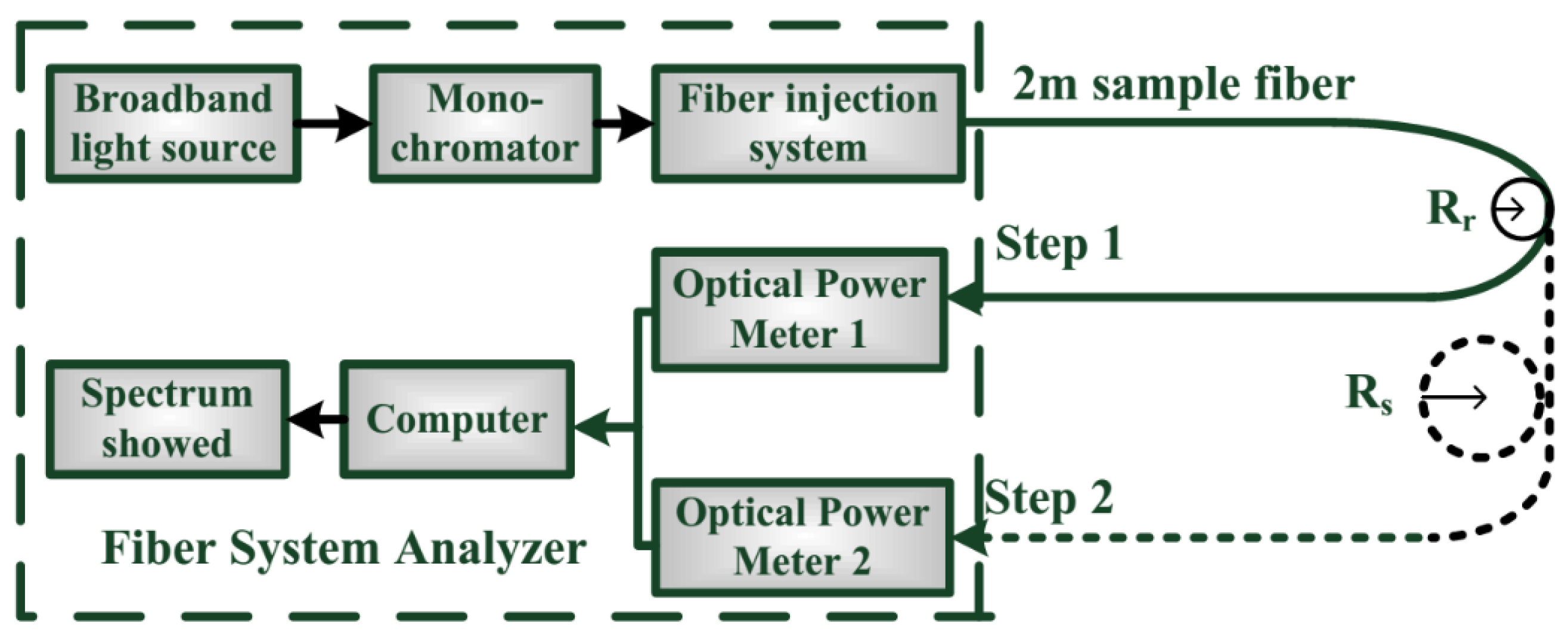
The number of guided modes within the homemade CMCF was experimentally measured. With a fiber analysis system (Photon Kinetics 2210), the cutoff wavelength of the CMCF was analyzed and measured by the transmitted power technique specified in IEC 6079-1-44-2001 and GB/T 15972.44-2008. The system architecture is given in Figure 11. The fiber analysis system consisted of a shaped FWHM broadband white light source, a monochromator, a fiber injection system, an optical power meter, a calculation system, and a display system. The monochromator could be adjusted to achieve different test bandwidths of the optical injection beam, which operated in the wavelength range of 800~1700 nm. The operational principle was to obtain the cutoff wavelength of the fiber by measuring the variation of the transmitted power vs. wavelength with two different bending radii.
R(λ) = 10lg[Ps(λ)/Pr(λ)]
When the energy of guided modes is nearly the same, Pr(λ) is the total transmitted power, and Ps(λ) is the power of all modes below a certain higher-order mode. When R(λ) reduces to 0.1 dB, the corresponding one is the cutoff wavelength to that higher-order mode. Rs is the large bending radius, while Rr is the small bending radius.
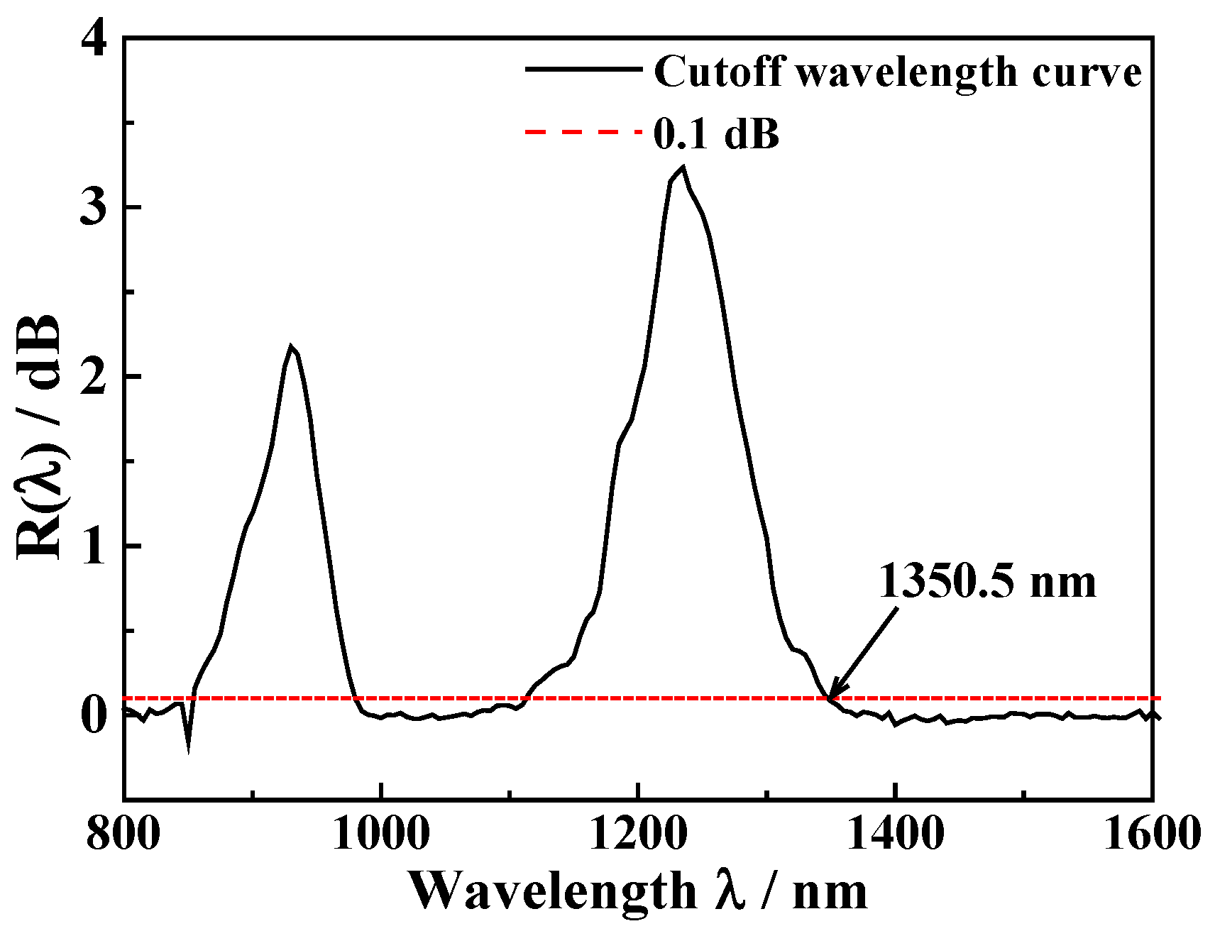
Since this CMCF was not liable to high bending loss, Rr could not be taken as 30 mm with the requirements of IEC 6079-1-44-2001 but a smaller bending radius, which made R(λ) > 2 dB. Through the parameter optimization, Rr was set as 20 mm, and the measurement curve of the cutoff wavelength was obtained as shown in Figure 12. There were two peaks, which represented the leakage loss of the high-order mode, so the cutoff wavelength was obtained as 1350.5 nm when the R(λ) of the far-right peak was down to 0.1 dB. Only the fundamental mode could be propagated in the CMCF at 1550 nm. The radius of the fundamental mode, ω0 = 8.5 μm, was calculated by the Petermann II formula, which doubled the one of Coning SMF-28 [30]. The large-mode-area fiber structure effectively suppressed the fiber nonlinearity, which was beneficial to fiber-to-fiber coupling at high power. The single-mode CMCF with low nonlinearity could become a potential candidate for fabricating a new type of collimator in laser beam coupling systems.
3.2. Measurement and Discussion of Geometric Deviations
A new collimator based on the large-mode-area single-mode CMCF was fabricated. Its alignment redundancy test was to verify whether the angular deviation performance was improved by the theoretical analysis in Section 2. When the CMCF-based collimator was used in the test system, a mode mismatch occurred at the fusion point with the SMF, which usually results in high fusion loss. Our team fused SMFs to CMCFs by the manual mode of a special fiber fusion splicer (FujikuraTM, FSM-100 M/P), and the loss was as low as 0.1 dB. Beam expanding fibers were obtained by the manual fusion mode, the principal reason was Ge ion diffusion in SMF by an electrical discharge. Therefore, the fusion loss was reduced.
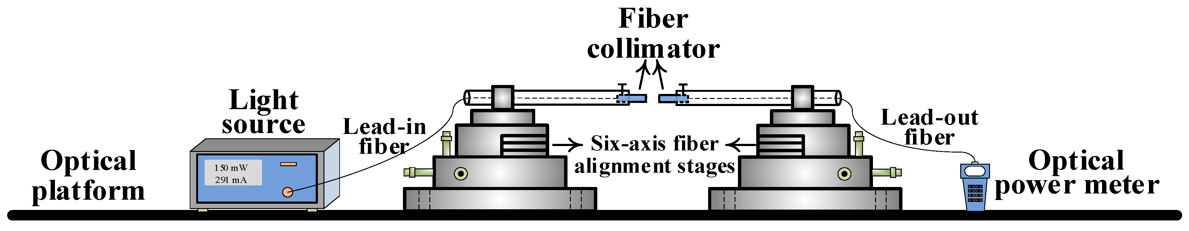
The experimental setup for measuring the coupling deviation is shown in Figure 13. Two fiber collimators were fixed on two six-axis fiber alignment stages by homemade clamps. This experimental architecture was developed, which consisted of a homemade single-mode fiber laser as the light source, and an optical power meter for coupling loss measurement. This light source had a stable output at 1550 nm, whose power was set at 5 dBm. The fiber alignment stage was utilized for position alignment to minimize the coupling loss, which served as a starting point. Then the quantitative measurements were performed in three types of geometric deviations, from which the corresponding coupling loss was obtained.
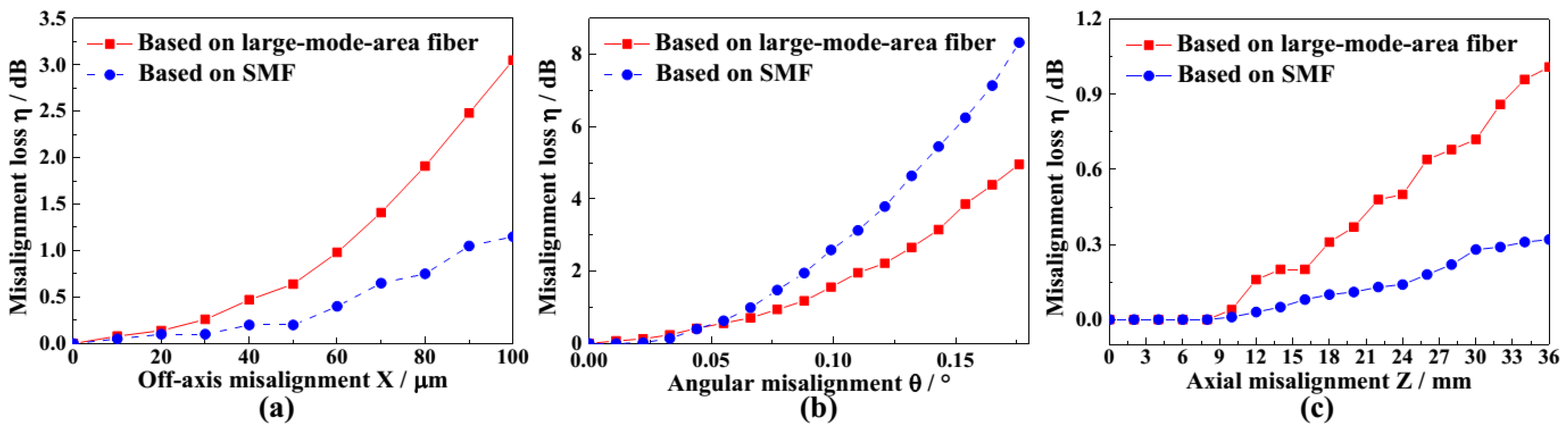
The coupling loss with the collimators with the CMCF was carried out by experimental measurements and study, and the ones with Coning SMF-28 were set as the experimental control group. Under the same optimal conditions, the coupling loss between the two SMF-based collimators was 0.25 dB, while the one between the two CMCF-based collimators was 0.37 dB. The coupling loss of off-axis, angular, and axial deviations was measured in the laboratory, as shown in Figure 14. Due to the limitation of the fiber alignment stage, the axial deviation was only measured to 36 mm. Table 1 gives the geometric deviations caused by misalignment for the two control experiments (SMF- and CMCF-based) when the coupling loss η was certain. The experimental results show that the angular redundancy improved by 20% and off-axis redundancy decreases = d by 31.6% for η = 1 dB. The axial redundancy decreased by 68.75% for η = 0.2 dB. The results of the simulation and experiments, which were consistent with each other, indicate that the collimators with the large-mode-area CMCF improved the angular deviation, which is significant for the design of the collimators used in laser beam coupling.
4. Conclusions
In this research, a homemade single-mode collimator based on the large-mode-area CMCF was fabricated and demonstrated for spatial coupling of the laser. The coupling loss in off-axis, angular, and axial aspects of this collimator was theoretically analyzed and laboratory measured. Due to the special features of CMCFs, the overall performance of this homemade collimator was significantly improved. Of these, the average deviation of the angular orientation, when the laser beam was coupled to this collimator, was enhanced by 20%. It greatly reduced the difficulty of the spatial coupling of laser beams and improved the quality of optical signal transmission. This homemade collimator with good alignment performance can provide a basis for next-generation optical communication.
Author Contributions
Conceptualization, methodology, X.Z. and X.L.; validation, Z.B. and X.L.; formal analysis, X.Z. and X.L.; investigation, X.Z. and X.L.; writing—original draft preparation, Z.G. and T.Y.; writing—review and editing, X.Z., Z.B. and X.L.; visualization, X.Z. and T.Y.; supervision, X.L. and S.L.; project administration, X.L.; funding acquisition, X.L. All authors have read and agreed to the published version of the manuscript.
Funding
This research was funded by the National Natural Science Foundation of China, grant numbers 61905293, 61774175 and the Young Teachers Research Ability Enhancement Project @ Minzu University of China, grant number 2021QNPY11.
Institutional Review Board Statement
Not applicable.
Informed Consent Statement
Not applicable.
Data Availability Statement
Not applicable.
Conflicts of Interest
The authors declare no conflict of interest.
References
- Jia, D.; Jing, W.; Zhang, Y.; Wang, G.; Tang, F.; Zhang, J. Bidirectional dynamic data transmission through a rotary interface. Opt. Eng. 2005, 44, 050503. [Google Scholar] [CrossRef]
- Zhang, M.; Zhi, D.; Ma, Y.; Ma, P.; Su, R.; Wu, J.; Zhou, P.; Si, L. Coherent fiber-optics-array collimator based on a single unitary collimating lens: Proposal design and experimental verification. Appl. Opt. 2019, 58, 1491–1495. [Google Scholar] [CrossRef] [PubMed]
- Jung, Y.; Alam, S.-U.; Richardson, D.J. Compact few-mode fiber collimator and associated optical components for mode division multiplexed transmission. In Proceedings of the 2016 Optical Fiber Communications Conference and Exhibition (OFC), Anaheim, CA, USA, 20–24 March 2016; pp. 1–3. [Google Scholar]
- Huang, G.; Geng, C.; Li, F.; Liu, J.; Li, X. Control bandwidth promotion of adaptive fiber-optics collimator and its application in coherent beam combination. IEEE Photonics J. 2018, 10, 1–13. [Google Scholar] [CrossRef]
- Sousa, A.N.E.; Ferreira, R.; Alimi, I.; Shahpari, A.; Lima, M.; Teixeira, A. Bidirectional SMF and PF-POF transmission of 400 Gbps Nyquist shaped on DP-QPSK systems. Microw. Opt. Technol. Lett. 2019, 61, 256–260. [Google Scholar] [CrossRef] [Green Version]
- Blomqvist, M.; Pålsson, M.; Blomster, O.; Manneberg, G. Fundamental-mode fiber-to-fiber coupling at high-power. In Proceedings of the Solid State Lasers XVIII: Technology and Devices, San Jose, CA, USA, 25–29 January 2009; p. 71930. [Google Scholar]
- Krzempek, K.; Tomaszewska, D.; Głuszek, A.; Martynkien, T.; Mergo, P.; Sotor, J.; Foltynowicz, A.; Soboń, G. Stabilized all-fiber source for generation of tunable broadband fCEO-free mid-IR frequency comb in the 7–9 µm range. Opt. Express 2019, 27, 37435–37445. [Google Scholar] [CrossRef]
- Denisov, V.I.; Ivanenko, A.V.; Nyushkov, B.N.; Pivtsov, V.S. Femtosecond fibre laser with a hybrid linear-ring cavity. Quantum Electron. 2008, 38, 801–802. [Google Scholar] [CrossRef]
- Nyushkov, B.; Kobtsev, S.; Antropov, A.; Kolker, D.; Pivtsov, V. Femtosecond 78-nm tunable Er:fibre Laser Based on Drop-shaped Resonator Topology. J. Lightwave Technol. 2019, 37, 1359–1363. [Google Scholar] [CrossRef]
- Wan, Q.; Wan, Z.; Liu, H.; Liu, D. A two-in-one Faraday rotator mirror exempt of active optical alignment. Opt. Express 2014, 22, 3557–3563. [Google Scholar] [CrossRef]
- Mi, L.; Yao, S.; Sun, C.; Bo, S.; Zhang, H. A single-channel fiber optic rotary joint on the basis Of TEC fiber collimators. In Proceedings of the International Conference on Optical Communications & Networks, Guangzhou, China, 5–7 December 2011. [Google Scholar]
- Feng, D.; Wan, Z.; Chen, X.; Yan, S.; Luo, Z. An optical tunable filter array based on LCOS phase grating. In Proceedings of the 2017 International Conference on Optical Instruments and Technology: Optoelectronic Devices and Optical Signal Processing, Beijing, China, 28–30 October 2017; p. 106170. [Google Scholar]
- Zhang, M.; Ma, Y.; Long, J.; Ma, P.; Su, R.; Wu, J.; Zhou, P.; Si, L. Realization of 7-channel beam coherent beam combination based on coherent fiber-optics-array collimator. In Proceedings of the AOPC 2019: Advanced Laser Materials and Laser Technology, Beijing, China, 7–9 July 2019; p. 113330. [Google Scholar]
- Zhang, F.; Xu, X.; He, J.; Du, B.; Wang, Y. Highly sensitive temperature sensor based on a polymer-infiltrated Mach–Zehnder interferometer created in graded index fiber. Opt. Lett. 2019, 44, 2466–2469. [Google Scholar] [CrossRef] [PubMed]
- Zhang, W.; Chen, F.; Ma, W.; Rong, Q.; Qiao, X.; Wang, R. Ultrasonic imaging of seismic physical models using a fringe visibility enhanced fiber-optic Fabry-Perot interferometric sensor. Opt. Express 2018, 26, 11025–11033. [Google Scholar] [CrossRef] [PubMed]
- Zhi, D.; Ma, Y.; Chen, Z.; Wang, X.; Zhou, P.; Si, L. Large deflection angle, high-power adaptive fiber optics collimator with preserved near-diffraction-limited beam quality. Opt. Lett. 2016, 41, 2217–2220. [Google Scholar] [CrossRef] [PubMed]
- Wood, A.; Jung, Y.; Richardson, D.J. Multiport Fiber Optic Beam Splitters for Space Division Multiplexed (SDM) Systems. IEEE Photonics Technol. Lett. 2020, 32, 795–798. [Google Scholar] [CrossRef]
- Beresnev, L.A.; Motes, R.A.; Townes, K.J.; Marple, P.; Gurton, K.; Valenzuela, A.R.; Williamson, C.; Liu, J.J.; Washer, C. Design of a noncooled fiber collimator for compact, high-efficiency fiber laser arrays. Appl. Opt. 2017, 56, B169–B178. [Google Scholar] [CrossRef] [PubMed]
- Marciniak, C.D.; Ball, H.B.; Hung, A.T.-H.; Biercuk, M.J. Towards fully commercial, UV-compatible fiber patch cords. Opt. Express 2017, 25, 15643–15661. [Google Scholar] [CrossRef] [Green Version]
- Li, F.; Geng, C.; Huang, G.; Yang, Y.; Li, X.; Qiu, Q. Experimental demonstration of coherent combining with tip/tilt control based on adaptive space-to-fiber laser beam coupling. IEEE Photonics J. 2017, 9, 7102812. [Google Scholar] [CrossRef]
- Hu, Q.; Li, C. The new tapered fiber connector and the test of its error rate and coupling characteristics. Int. J. Opt. 2017, 2017, 2742709. [Google Scholar] [CrossRef] [Green Version]
- Dong, X.; Li, P.; Zhang, X.; Yang, W. Analysis of Alignment Errors of Beam-Expanded Optical Fiber Connector Based on ZEMAX. Laser Optoelectron. Prog. 2020, 57, 152201. [Google Scholar] [CrossRef]
- Wakabayashi, M.; Yokota, H.; Imai, Y. Optical coupling characteristics of graded-index type photonic crystal fiber collimator depending on air hole diameter ratio to pitch. Opt. Rev. 2019, 26, 590–596. [Google Scholar] [CrossRef]
- Unger, A.; Küster, M.; Köhler, B.; Biesenbach, J. High-power fiber-coupled 100W visible spectrum diode lasers for display applications. In Proceedings of the High-Power Diode Laser Technology and Applications XI, San Francisco, CA, USA, 3–5 February 2013; p. 86050. [Google Scholar]
- Yuan, S.; Riza, N.A. General formula for coupling-loss characterization of single-mode fiber collimators by use of gradient-index rod lenses. Appl. Opt. 1999, 38, 3214–3222. [Google Scholar] [CrossRef]
- Qingji, H.W.Z. Misalignment induced Excess Loss in Gradient index rod Lens Collimating Systems. Chin. J. Lasers 1999, 26, 221. [Google Scholar]
- Gilsdorf, R.W.; Palais, J.C. Single-mode fiber coupling efficiency with graded-index rod lenses. Appl. Opt. 1994, 33, 3440–3445. [Google Scholar] [CrossRef] [PubMed]
- Jing, W.; Jia, D.; Tang, F.; Zhang, H.; Zhang, Y.; Zhou, G.; Yu, J.; Kong, F.; Liu, K. Design and implementation of a broadband optical rotary joint using C-lenses. Opt. Express 2004, 12, 4088–4093. [Google Scholar] [CrossRef] [PubMed]
- Damask, J.N. Polarization Optics in Telecommunications. Springer Science & Business Media: New York, NY, USA, 2004; Volume 101. [Google Scholar]
- Liang, X.; Ren, G.; Liu, S.; Liu, Z.; Li, Y.; Jian, S. Characteristics of HE 11-HE 21 mode elliptical multilayer-core fiber with low nonlinearity. Opt. Eng. 2014, 53, 105104. [Google Scholar] [CrossRef]
Figure 1.
Structure of fiber collimator and coupling in an ideal case.

Figure 2.
Alignment deviation.

Figure 3.
Off-axis deviation.

Figure 4.
Coupling loss due to off-axis deviation.

Figure 5.
Angular deviation.

Figure 6.
Coupling loss due to angular deviation.

Figure 7.
Axial deviation.

Figure 8.
Coupling loss due to axial deviation.

Figure 9.
Structure of (a) CMCF and (b) collimator.

Figure 10.
(a) the cross–section and (b) refractive index profile of the homemade CMCF.

Figure 11.
Schematic of transmission power method for the cutoff wavelength of the fiber.

Figure 12.
The measuring R(λ)~λ curve by the improved transmission power method.

Figure 13.
The experimental architecture of measuring deviations between two collimators.

Figure 14.
Coupling loss of (a) off-axis deviation; (b) angular deviation; (c) axial deviation.


Table 1.
Table of geometric deviations caused by misalignment measured in lab.
| Misalignment | η | MCF | SMF | Improvement |
|---|---|---|---|---|
| Off-axis X/μm | 1 dB | 60.3 | 88.2 | −31.6% |
| Angular θ/° | 1 dB | 0.078 | 0.065 | 20% |
| Axial Z/mm | 0.2 dB | 27 | 16 | −68.75% |
Publisher’s Note: MDPI stays neutral with regard to jurisdictional claims in published maps and institutional affiliations. |
© 2021 by the authors. Licensee MDPI, Basel, Switzerland. This article is an open access article distributed under the terms and conditions of the Creative Commons Attribution (CC BY) license (https://creativecommons.org/licenses/by/4.0/).
Share and Cite
MDPI and ACS Style
Zhang, X.; Liang, X.; Bai, Z.; Liu, S.; Geng, Z.; Yin, T. Characteristics of Collimators Based on the Large-Mode-Area CMCF for Coupling Laser Beam. Appl. Sci. 2021, 11, 11604. https://doi.org/10.3390/app112411604
AMA Style
Zhang X, Liang X, Bai Z, Liu S, Geng Z, Yin T. Characteristics of Collimators Based on the Large-Mode-Area CMCF for Coupling Laser Beam. Applied Sciences. 2021; 11(24):11604. https://doi.org/10.3390/app112411604
Chicago/Turabian StyleZhang, Xuran, Xiao Liang, Zhenxu Bai, Shuo Liu, Zhaoxin Geng, and Tianhe Yin. 2021. "Characteristics of Collimators Based on the Large-Mode-Area CMCF for Coupling Laser Beam" Applied Sciences 11, no. 24: 11604. https://doi.org/10.3390/app112411604
Note that from the first issue of 2016, this journal uses article numbers instead of page numbers. See further details here.