Article

Model-Predictive-Control-Based Time-Optimal Trajectory Planning of the Distributed Actuation Mechanism Augmented by the Maximum Performance Evaluation

1
Cho Chun Shik Graduate School of Green Transportation, Korea Advanced Institute of Science and Technology (KAIST), Daejeon 34051, Korea
2
Center for Eco-Friendly & Smart Vehicles, Korea Advanced Institute of Science and Technology (KAIST), Daejeon 34141, Korea
*
Author to whom correspondence should be addressed.
Appl. Sci. 2021, 11(16), 7513; https://doi.org/10.3390/app11167513
Submission received: 25 June 2021 / Revised: 12 August 2021 / Accepted: 12 August 2021 / Published: 16 August 2021
(This article belongs to the Section Robotics and Automation)

Abstract

:
Trajectory planning for a redundant manipulator is a classic problem. However, because it is difficult to precisely evaluate its maximum performance, an optimization method has been typically used. In this study, a novel time-optimal trajectory planning method for a redundant manipulator is proposed using the model predictive control (MPC) augmented by the maximum performance evaluation (MPE). First, the optimization formulation is expressed to evaluate the maximum performance of the distributed-actuation-mechanism-based three-revolute-joint manipulator (DAM-3R), which has a high level of redundancy, and the joint-actuation-mechanism-based three-revolute-joint manipulator (JAM-3R) for comparison. The optimization is conducted by linking the multibody dynamics analysis module and the optimization module. For time-optimal trajectory planning, the MPC problem is then formulated using mathematical performance models for the DAM-3R and JAM-3R based on the MPE results, which are considered as the upper bound of the manipulator performance at each end-effector position. To verify the proposed method, a point-to-point task with no predefined path is investigated. The simulation results show that the working time of the DAM-3R is 19.1% less than that of the JAM-3R. Moreover, the energy consumption for the DAM-3R is 45.0% lower than that for the JAM-3R by optimally utilizing the higher redundancy of the DAM-3R. Thus, it can be concluded that the proposed method is effective for time-optimal trajectory planning for redundant manipulators.

1. Introduction

Trajectory planning is an ever-challenging issue in robotics. A typical category of trajectory planning problems is time-optimal trajectory planning [1,2,3]. Another popular category is to minimize energy consumption [4,5,6,7,8]. In addition, limiting the joint speed and acceleration [9] and minimizing the actuation force [10], joint torques [11], and joint wear [12] have been widely studied. However, most studies have been limitedly conducted under a predefined fixed path.
To overcome the above limitation, model predictive control (MPC) has been recently used to solve time-optimal trajectory problems with given initial and end points only [13,14]. This approach can create both the optimal path (i.e., the locus of points in the task space) and the optimal trajectory (i.e., a path on which a timing law is specified) for a minimal operation time. Note that this is essential for point-to-point motion control with no predefined path. However, implementing MPC requires an explicit mathematical model that can precisely express the dynamic performance of the system. Thus, there exists a technical hurdle to implementing MPC-based trajectory planning for redundant manipulators because it is difficult to determine their mathematical performance model.
In robotics, redundant manipulators are widely used because they provide an increased level of dexterity by virtue of having more degrees of freedom (DOFs) in the joint space than those required to execute a given task. The additional DOFs in the joint space can be used to avoid obstacles [15,16], joint limits [17], and collision with other robots [18], and also to minimize joint velocity and acceleration [19] and joint torque [20]. They also provide an advantage in performing maintenance and inspection tasks [21]. Among various redundant manipulators, the distributed actuation mechanism (DAM) can enhance the fingertip force through relocating a redundant actuation point of a slider along the link without changing the posture [22,23]. However, such redundancy inevitably leads to difficulty in precisely evaluating its performance and thereby determining an optimal trajectory for a given task.
It is interesting to note that the bioinspired variable gearing of the three-link DAM has been recently investigated to maximize the manipulation performance [24]. Because the positions of the six redundant sliders, which actuate three joints, function as a gear ratio, the DAM can achieve better performance than the power-equivalent joint actuation mechanism (JAM). A gradient-based optimization algorithm was implemented to precisely conduct maximum performance evaluation (MPE) under redundant DOFs.
This paper proposes a novel time-optimal trajectory planning method for redundant manipulators by conducting MPC using the MPE results. First, the DAM-based three-revolute-joint manipulator (DAM-3R) was analyzed to obtain the MPE results using gradient-based optimization. The MPE results were used to construct an explicit performance model for the redundant DAM-3R as the upper bound of the manipulator performance at each end-effector position. Then, MPC was conducted to determine a time-optimal trajectory using the explicit performance model. For comparison, the JAM-based three-revolute-joint manipulator (JAM-3R), which is also a redundant manipulator, was constructed and analyzed to have equivalent power and geometric specifications.
This study is organized as follows. In Section 2, based on a brief explanation on the concept of the MPE, the MPE results for the DAM-3R and JAM-3R are obtained using gradient-based optimization. Section 3 describes the MPC formulation to determine a time-optimal trajectory for the DAM-3R. The JAM-3R is compared to demonstrate the validity and significance of the proposed method. The conclusions follow in Section 4.

2. Maximum Performance Evaluation

2.1. Optimization Formulation

The dexterity motion of a human finger is not achieved by lumped actuation, but by spatially distributed actuation of opponens pollicis (Figure 1a). Based on the understanding of such spatially distributed actuation, the DAM was designed to actuate one joint by thrusting two sliders along a link [22] (Figure 1b)). Because its joint angular velocity and torque vary depending on the position of the sliders (i.e., the application point of force), the DAM is a redundantly actuated system.
In principle, the optimization formulation can be expressed to precisely evaluate the maximum performance of a manipulator [25], as follows:
Find x 1 , x 2 , , a n d x n To maxmize f ( x ) = | v e ( x ) | Subject to h = d k v e = | d k | | v e | k = 1 , , K g ν ( x ) 0 ν = 1 , , N x i ( l ) x i x i ( u ) i = 1 , , n
where the superscripts (l) and (u) denote the lower and upper bounds of the design variable xi; the objective function f is the norm of the end-effector velocity; h is the equality constraint that matches the direction of the end-effector velocity ve with the base direction dk; and gν is the inequality constraint that represents motor performance.
Figure 2 shows a DAM-based three-revolute-joint manipulator (DAM-3R), which was investigated in this study. The position and velocity of the sliders can be treated as control variables that determine the end-effector velocity, ve= (vx, vy). For the DAM-3R, the design variable vector becomes x = [θ1, s1, s2, s3, 1, 2, 3, 1b, 2b, 3b], where θ1 is the first joint angle; s1, s2, and s3 are the positions of the front sliders; 1, 2, and 3 are the thrusting speeds of the front sliders; and 1b, 2b, and 3b are the thrusting speeds of the back sliders. In this study, the base direction dk was defined as follows:
d k = [ cos α , sin α ] T
where α is at intervals of 22.5 degrees from 0 to 360 degrees. This generated a total of 16 base directions (i.e., K = 16 in (1)). Because the speed and force of the sliders must operate within motor characteristics curves in four quadrants, gν was formulated as follows:
g 1 = F j ± F max s ˙ max s ˙ j ± F max 0 j = 1 , 2 , 3 g 2 = F j b ± F max s ˙ max s ˙ j b ± F max 0 j = 1 , 2 , 3
where the subscript j indicates the joint number; Fj and Fjb are the thrusting force of the front slider and back slider, respectively; Fmax is the maximum thrusting force of the front and back sliders; and max is the maximum thrusting speed of the front and back sliders. In this study, gravitational force was applied as an external force to reflect inertia loads.
For comparison, a joint actuation mechanism (JAM)-based three-revolute-joint manipulator (JAM-3R) was also considered with power-equivalent motors and the same geometric specifications (Figure 3 and Table 1). When the end-effector is free to rotate, the first joint angle θ1 becomes a control variable. Accordingly, the JAM-3R is also a redundant manipulator, but it has less redundancy than the DAM-3R. We note that, for both the DAM-3R and JAM-3R, the motors for Joint 1 were set to have a higher gear ratio than those for Joints 2 and 3 (Table 2 and Table 3) because Joint 1 (Figure 2) requires a larger torque due to its higher moment of inertia. The same optimization formulation except for the design variables and motor characteristics can be used for the JAM-3R, as expressed in (1). Here, the design variable vector became x = [θ1, θ ˙ 1 , θ ˙ 2 , θ ˙ 3 ], where θ ˙ 1 , θ ˙ 2 , and θ ˙ 3 are the joint speeds. To express lumped joint actuation, the inequality constraint function g, which represents the motor characteristics curve, was modified as follows:
g = τ j ± τ max θ ˙ max θ ˙ j ± τ max 0 j = 1 , 2 , 3
where τj is the joint torque; τmax is the maximum joint torque; and θ ˙ max is the maximum joint speed.

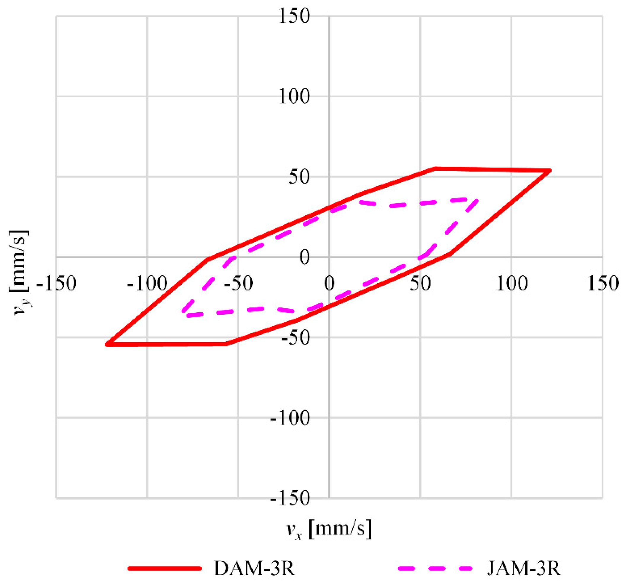
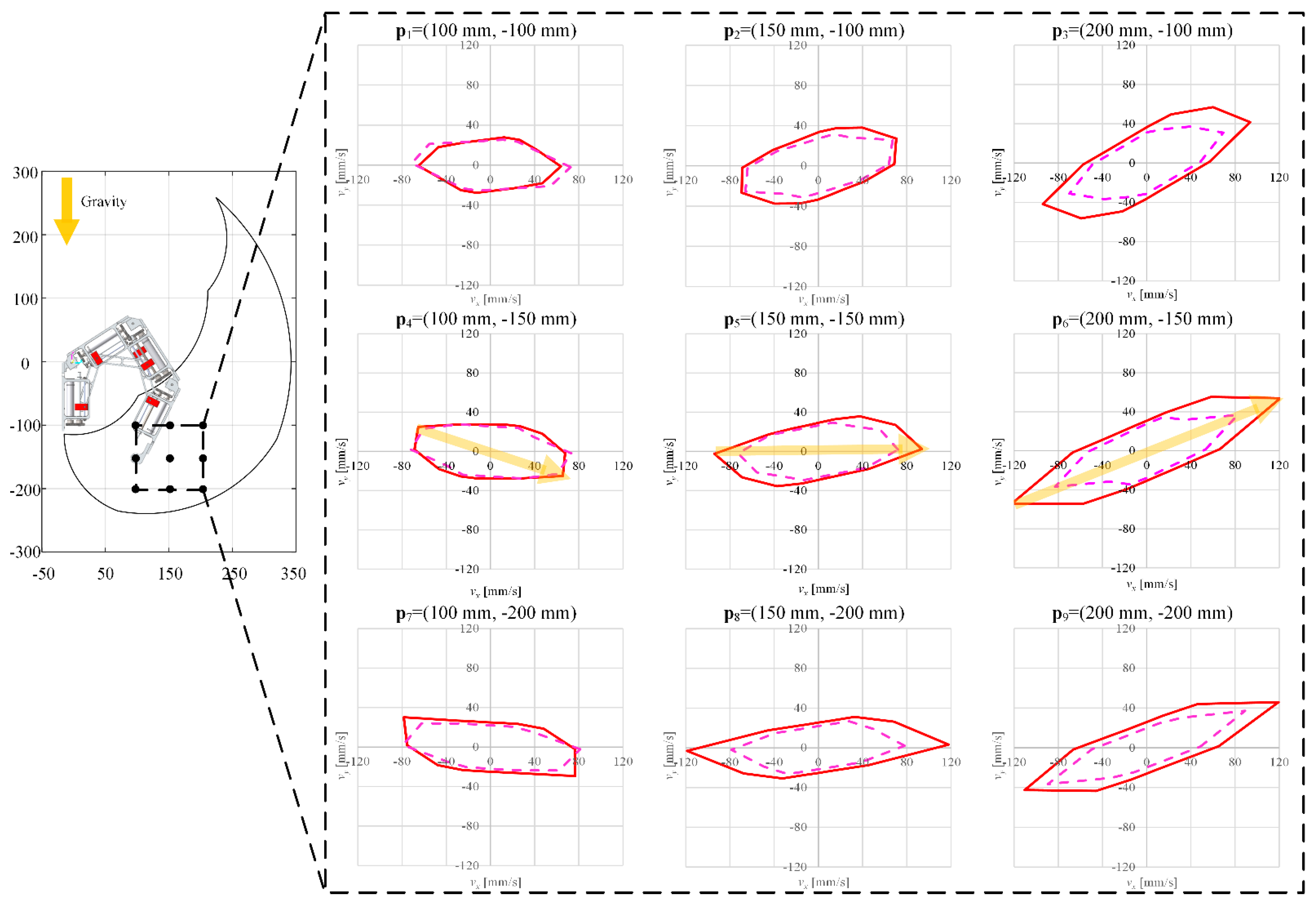
2.2. Numerical Results

In this study, RecurDyn (FunctionBay, Inc., Seongnam, Korea, commercial multibody dynamics software) was used to evaluate the dynamic behavior of the DAM-3R and JAM-3R. To solve (1), the optimization framework was constructed based on the analysis module (RecurDyn) and the optimization module (in-house code written in MATLAB) (Figure 4). As shown in Figure 4, RecurDyn imports the CAD model of a target manipulator to create an initial model for the multibody dynamics analysis. The updated design variables are transferred to RecurDyn to translate and/or rotate the model. Then, RecurDyn performs multibody dynamics analysis and sends the simulation results to the optimization module. The optimization module evaluates the objective and constraint function values (end-effector velocity and thrusting force, respectively) and then calculates the sensitivity of each design variable by using the finite difference method (FDM). If the convergence criterion is satisfied, the optimization process is terminated. Otherwise, the above process continues. Sequential quadratic programming in the MATLAB optimization toolbox [26] was selected as the optimization algorithm. The computing environment for the simulation was as follows: AMD Ryzen 7 5800X 8-Core Processor (CPU), NVIDIA GeForce GTX 1080 Ti (GPU), and DDR4 64GB (RAM). The parameters used in the simulation are summarized in Table 2 and Table 3.
The MPE results at the end-effector position pe= (200 mm, −150 mm) can be represented in the form of polygons (the so-called allowable polygons in [25]), as shown in Figure 5. The performance results of the DAM-3R and JAM-3R are expressed in solid and dotted lines, respectively. It can be clearly seen that the end-effector velocity of the DAM-3R was greater for all 16 base directions than that of the JAM-3R with no payload. As explained in our previous work [24], this is due to an appropriate change in the gear ratio depending on the position of the sliders.
Figure 6 shows the MPE results for both the DAM-3R and JAM-3R at nine target positions equidistantly distributed in the workspace (Figure 6). Although the DAM-3R used a motor with 1.7% less power (Table 1), the maximum end-effector velocity was up to 31.9% higher at (200 mm, −150 mm).
The MPE results obtained above can be considered as the upper bounds of the maximum end-effector velocity at each end-effector position. Under such velocity constraints, the dynamics of the end-effector position can be expressed by using a first-order model in MPC (see Section 3.2 for more details), which can significantly simplify the MPC formulation for time-optimal trajectory planning without a significant loss of accuracy. We note that it is difficult to precisely evaluate the maximum performance of a redundant manipulator such as a DAM without the aid of the MPE.

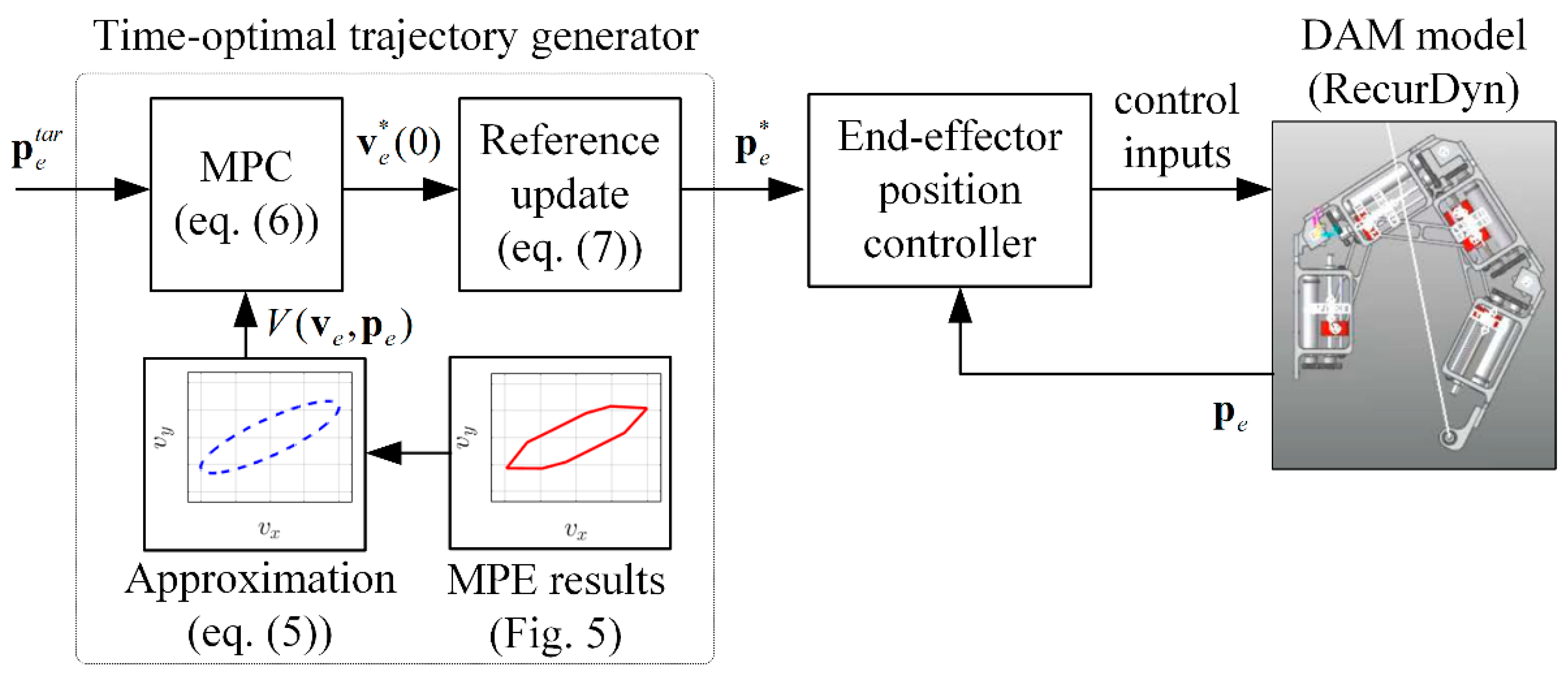
3. Time-Optimal Trajectory Planning Based on the MPE and MPC

In an ideal case, the allowable velocity polygon at each end-effector position can be expressed in the form of piecewise linear functions, as shown in Figure 6. However, such polygons should be formulated at all positions in the workspace to conduct MPC. To overcome the above computing issue, it is necessary to approximate the allowable velocity polygon in the entire workspace in a more efficient way.

3.1. Approximation of the MPE Results

For practical purposes, the maximum end-effector velocity polygons at the end-effector position pe can be approximated as an ellipse, as follows:
V ( v e , p e ) = ( v x cos c + v y sin c ) 2 a 2 + ( v x sin c v y cos c ) 2 b 2 1 = 0 ,
where a and b are the radii of the major and minor axes of the ellipse, respectively, and c is the angle between the major axis and vx-axis. Note that the parameters a, b, and c are functions of pe because the shape of an ellipse varies depending on the end-effector position pe, as shown in Figure 5. After these parameters (a, b, and c) were determined at the nine target positions by using the least squares method, second-order polynomials for a, b, and c were constructed to cover the entire workspace via the least squares method. Consequently, the MPE results were approximated by a mathematical form for the end-effector velocity, i.e., V ( v e , p e ) 0 .

3.2. Problem Formulation

Time-optimal trajectory planning can be formulated in the MPC framework [13] as follows:
Find Δ T ( l ) and v e ( l ) for l = 0 , 1 , , N p 1 to minimize l = 0 N p 1 Δ T ( l ) subject to p e ( l + 1 ) = p e ( l ) + Δ T ( l ) v e ( l ) V ( v e ( l ) , p e ( l ) ) 0 Δ T ( l ) > 0 p e ( N p ) = p e tar
where l denotes a time step; ΔT(l) denotes the time interval of each time step; Np denotes the prediction horizon length; and p e t a r denotes the target end point of the end-effector position.
By solving (6), the optimal trajectories of ΔT and ve (i.e., ΔT * and ve*) can be obtained to approach the target p e t a r in minimum time within the prediction horizon Np. Only the optimal velocity at the first time step (i.e., ve*(0)) was used to calculate the reference pe* for the end-effector position controller, as follows:
p e * p e * + T s v e * ( 0 ) ,
where Ts is the control period of the end-effector position controller. In [7], the initial values of pe* were selected based on the MPE results of the DAM-3R and JAM-3R. T s was used instead of the optimal time interval ΔT*(0), which could be greater than Ts, so that the reference pe* could be tracked by the controller at each control step.
It should again be noted that the time-optimal MPC formulation in (6) requires constraints on the maximum performance of the end-effector (i.e., V(⸱) ≤ 0). It is practically difficult to solve such an MPC problem without having explicit and accurate performance models of the manipulator. In this study, the mathematical performance models for the DAM-3R and JAM-3R were generated based on the MPE results. We note that, in this study, the dynamics of the end-effector position were simplified by using a first-order model in the MPC ( p e ( l + 1 ) = p e ( l ) + Δ T ( l ) v e ( l ) in (6)) thanks to the MPE-based performance models ( V ( v e ( l ) , p e ( l ) ) 0 in (6)). This led to a fast and accurate simulation.

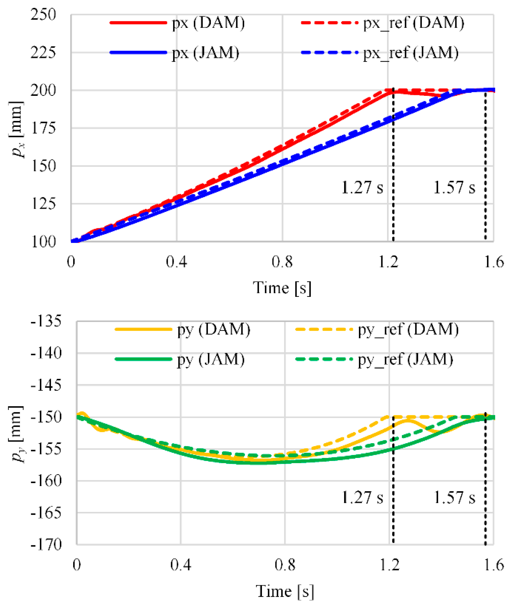
3.3. Numerical Results

A point-to-point task (start position p4 and end position p6 in Figure 6) was set with no predetermined path. To solve (6) for the DAM-3R and JAM-3R, a simulation framework was constructed using MATLAB Simulink for time-optimal trajectory planning and RecurDyn for multibody dynamics analysis (Figure 7). The time-optimal MPC was solved using the Model Predictive Control Toolbox in MATLAB 2020a [27]. The prediction horizon length Np was 10, and the control period Ts was 1 ms.
Figure 8 shows the time-optimal trajectory results for the end-effector reference position (dashed line) and actually controlled position through the controller (solid line). The arrival time of the JAM-3R was 1.57 s, whereas that of the DAM-3R was 1.27 s (19.1% faster). It is interesting to note that the optimal trajectory in the y-axis for the DAM-3R and JAM-3R slightly descended by 6.2 mm and 6.1 mm, respectively, at the center of the path, p5 = (150 mm, −150 mm). This is because the direction of the time-optimal trajectory was well aligned with that of the maximum allowable velocities at p4, p5, and p6 (yellow highlighted arrows in Figure 6).
Figure 9 shows the detailed simulation results regarding the actuating forces and output motion in the joint space. Figure 9a,c represents the resultant actuating force and slider position, respectively, for the DAM-3R. Figure 9b,d also represents the resultant actuating torque and joint angle, respectively, for the JAM-3R. The total energy consumption of the DAM-3R was reduced by 45.0% compared with that of the JAM-3R (316.5 mJ for the DAM vs. 575.3 mJ for the JAM in Table 4). The proposed MPE-augmented MPC can fully and optimally utilize a high level of redundancy (additional design variables or control degrees of freedom) so as to move in the quickest manner. Particularly, for the DAM-3R, which has higher redundancy than the JAM-3R, the maximum velocity was achieved by less actuating of Joints 1 and 2, which have larger inertia and therefore require larger thrusting torque. This led to faster motion and less energy consumption for the DAM-3R compared with the JAM-3R. Thus, it is clear that, by virtue of conducting MPC augmented by MPE results (explicit and accurate performance models), a redundant manipulator can achieve higher performance in terms of working time and energy consumption for trajectory planning.

4. Conclusions

In this study, we proposed a novel concept of time-optimal trajectory planning for a redundant DAM based on MPE and MPC. This optimization technique for the DAM-3R and JAM-3R can precisely evaluate the maximum performance (velocity in this study) and, at the same time, determine the optimal control parameters. The MPC for time-optimal trajectory planning was then formulated with the mathematical performance models based on the MPE results obtained. To verify the proposed method, a multibody dynamics module and control analysis module were co-simulated for the DAM-3R and JAM-3R. The simulation results clearly demonstrate that the proposed method can successfully provide the time-optimal trajectory for redundant manipulators. In particular, the DAM-3R, which has higher redundancy than the JAM-3R, outperforms the JAM-3R in terms of working time and energy consumption.
Although we formulated a time-optimal optimization method for MPC, it could be expanded to various performance measures (or tasks), such as minimizing total energy consumption, minimizing the joint torques, and maximizing the end-effector force with limited resources. Therefore, this study could be extended to broad areas of trajectory planning, such as energy minimization, joint torque minimization, and end-effector force maximization with limited resources. Also, in future work, if the proposed method is implemented in a more powerful computing environment such as a parallel multicore system, the computing time could be significantly shortened.

Author Contributions

Conceptualization, J.H.K. and I.G.J.; methodology, J.H.K., K.C. and I.G.J.; software, J.H.K. and K.C.; validation, J.H.K., K.C. and I.G.J.; formal analysis, J.H.K., K.C. and I.G.J.; investigation, J.H.K., K.C. and I.G.J.; resources, J.H.K., K.C. and I.G.J.; data curation, J.H.K. and K.C.; writing—original draft preparation, J.H.K. and K.C.; writing—review and editing, I.G.J.; visualization, J.H.K. and K.C.; supervision, I.G.J.; project administration, I.G.J.; funding acquisition, I.G.J. All authors have read and agreed to the published version of the manuscript.

Funding

This research was supported by the KAIST-KU Joint Research Center, KAIST, Korea. (N11210040).

Institutional Review Board Statement

Not applicable.

Informed Consent Statement

Not applicable.

Data Availability Statement

Not applicable.

Conflicts of Interest

The authors declare no conflict of interest.

References

  1. Reiter, A.; Muller, A.; Gattringer, H. On Higher Order Inverse Kinematics Methods in Time-Optimal Trajectory Planning for Kinematically Redundant Manipulators. IEEE Trans. Ind. Inform. 2018, 14, 1681–1690. [Google Scholar] [CrossRef]
  2. Fang, Y.; Hu, J.; Liu, W.; Shao, Q.; Qi, J.; Peng, Y. Smooth and time-optimal S-curve trajectory planning for automated robots and machines. Mech. Mach. Theory 2019, 137, 127–153. [Google Scholar] [CrossRef]
  3. Benotsmane, R.; Dudás, L.; Kovács, G. Trajectory optimization of industrial robot arms using a newly elaborated “whip-lashing” method. Appl. Sci. 2020, 10, 8666. [Google Scholar] [CrossRef]
  4. Hansen, C.; Öltjen, J.; Meike, D.; Ortmaier, T. Enhanced approach for energy-efficient trajectory generation of industrial robots. In Proceedings of the 2012 IEEE International Conference on Automation Science and Engineering (CASE), Seoul, Korea, 20–24 August 2012; pp. 1–7. [Google Scholar] [CrossRef]
  5. Pellicciari, M.; Berselli, G.; Leali, F.; Vergnano, A. A method for reducing the energy consumption of pick-and-place industrial robots. Mechatronics 2013, 23, 326–334. [Google Scholar] [CrossRef]
  6. Lee, G.; Park, S.; Lee, D.; Park, F.C.; Jeong, J.I.; Kim, J. Minimizing Energy Consumption of Parallel Mechanisms via Redundant Actuation. IEEE/ASME Trans. Mechatron. 2015, 20, 2805–2812. [Google Scholar] [CrossRef]
  7. Carabin, G.; Scalera, L. On the Trajectory Planning for Energy Efficiency in Industrial Robotic Systems. Robotics 2020, 9, 89. [Google Scholar] [CrossRef]
  8. Tringali, A.; Cocuzza, S. Finite-Horizon Kinetic Energy Optimization of a Redundant Space Manipulator. Appl. Sci. 2021, 11, 2346. [Google Scholar] [CrossRef]
  9. Trigatti, G.; Boscariol, P.; Scalera, L.; Pillan, D.; Gasparetto, A. A Look-Ahead Trajectory Planning Algorithm for Spray Painting Robots with Non-spherical Wrists. In Mechanisms and Machine Science; Springer: Cham, Switzerland, 2019; Volume 66, pp. 235–242. [Google Scholar]
  10. Boudreau, R.; Nokleby, S. Force optimization of kinematically-redundant planar parallel manipulators following a desired trajectory. Mech. Mach. Theory 2012, 56, 138–155. [Google Scholar] [CrossRef]
  11. Al Khudir, K.; Halvorsen, G.; Lanari, L.; De Luca, A. Stable Torque Optimization for Redundant Robots Using a Short Preview. IEEE Robot. Autom. Lett. 2019, 4, 2046–2053. [Google Scholar] [CrossRef] [Green Version]
  12. Kot, T.; Bobovský, Z.; Vysocký, A.; Krys, V.; Šafařík, J.; Ružarovský, R. Method for Robot Manipulator Joint Wear Reduction by Finding the Optimal Robot Placement in a Robotic Cell. Appl. Sci. 2021, 11, 5398. [Google Scholar] [CrossRef]
  13. Rosmann, C.; Makarow, A.; Hoffmann, F.; Bertram, T. Time-Optimal nonlinear model predictive control with minimal control interventions. In Proceedings of the 2017 IEEE Conference on Control Technology and Applications (CCTA), Maui, HI, USA, 27–30 August 2017; Volume 2017-Janua, pp. 19–24. [Google Scholar]
  14. Van Den Broeck, L.; Diehl, M.; Swevers, J. A model predictive control approach for time optimal point-to-point motion control. Mechatronics 2011, 21, 1203–1212. [Google Scholar] [CrossRef]
  15. Shyh Chyan, G.; Ponnambalam, S.G. Obstacle avoidance control of redundant robots using variants of particle swarm optimization. Robot. Comput. Integr. Manuf. 2011, 28, 147–153. [Google Scholar] [CrossRef]
  16. Liu, J.; Tong, Y.; Ju, Z.; Liu, Y. Novel method of obstacle avoidance planning for redundant sliding manipulators. IEEE Access 2020, 8, 78608–78621. [Google Scholar] [CrossRef]
  17. Atawnih, A.; Papageorgiou, D.; Doulgeri, Z. Kinematic control of redundant robots with guaranteed joint limit avoidance. Rob. Auton. Syst. 2016, 79, 122–131. [Google Scholar] [CrossRef]
  18. Faroni, M.; Beschi, M.; Pedrocchi, N. Inverse Kinematics of Redundant Manipulators with Dynamic Bounds on Joint Movements. IEEE Robot. Autom. Lett. 2020, 5, 6435–6442. [Google Scholar] [CrossRef]
  19. Wiedmeyer, W.; Altoe, P.; Auberle, J.; Ledermann, C.; Kroger, T. A Real-Time-Capable Closed-Form Multi-Objective Redundancy Resolution Scheme for Seven-DoF Serial Manipulators. IEEE Robot. Autom. Lett. 2021, 6, 431–438. [Google Scholar] [CrossRef]
  20. Woolfrey, J.; Lu, W.; Liu, D. A Control Method for Joint Torque Minimization of Redundant Manipulators Handling Large External Forces. J. Intell. Robot. Syst. Theory Appl. 2019, 96, 3–16. [Google Scholar] [CrossRef] [Green Version]
  21. Chang, Q.; Luo, X.; Qiao, Z.; Li, Q. Design and motion planning of a biped climbing robot with redundant manipulator. Appl. Sci. 2019, 9, 3009. [Google Scholar] [CrossRef] [Green Version]
  22. Young June Shin; Kyung-Soo Kim Distributed-Actuation Mechanism for a Finger-Type Manipulator: Theory and Experiments. IEEE Trans. Robot. 2010, 26, 569–575. [CrossRef]
  23. June Shin, Y.; Ju Lee, H.; Kim, K.-S.; Kim, S. Output Force Enhancement of Finger-type Manipulator by Adopting Brushless DC Motors for Sliding Actuation. J. Mech. Eng. Autom. 2012, 2, 85–90. [Google Scholar] [CrossRef]
  24. Kim, J.H.; Jang, I.G. Optimization-Based Investigation of Bioinspired Variable Gearing of the Distributed Actuation Mechanism to Maximize Velocity and Force. IEEE Robot. Autom. Lett. 2020, 5, 6326–6333. [Google Scholar] [CrossRef]
  25. Kim, J.H.; Shin, Y.J.; Jang, I.G. Evaluating the Maximum Directional Kinematic Capability of a Redundant Manipulator Based on Allowable Velocity and Force. IEEE Access 2021, 9, 88085–88097. [Google Scholar] [CrossRef]
  26. Branch, M.A.; Grace, A. Optimization Toolbox: For Use with MATLAB: User’s Guide: Version 1; Math Works: Natick, MA, USA, 1998. [Google Scholar]
  27. Bemporad, A.; Morari, M.; Ricker, N.L. Model predictive control toolbox. In User’s Guid. Version; Math Works: Natick, MA, USA, 2004; Volume 2. [Google Scholar]
Figure 1. Actuation mechanism inspired by finger movement: (a) Spatially distributed actuation of a finger [24]; (b) A distributed actuation mechanism [22].
Applsci 11 07513 g001
Figure 2. A three-link planar manipulator equipped with the distributed actuation mechanism under the effects of gravity [24].
Applsci 11 07513 g002
Figure 3. A three-link planar manipulator equipped with a conventional joint actuation mechanism under the effects of gravity.
Applsci 11 07513 g003
Figure 4. Flowchart of the optimization framework using the analysis module (RecurDyn) and the optimization module (MATLAB).
Applsci 11 07513 g004
Figure 5. The maximum end-effector velocity evaluated for the DAM-3R (red solid line) and JAM-3R (magenta dotted line) at the end-effector position (200 mm, −150 mm).
Applsci 11 07513 g005
Figure 6. MPE results for the DAM-3R and JAM-3R at nine end-effector positions in the workspace.
Applsci 11 07513 g006
Figure 7. Proposed time-optimal trajectory planning using the MPE results and MPC method.
Applsci 11 07513 g007
Figure 8. Time-optimal trajectory results for the end-effector reference position (dotted line) and actually controlled position through the controller (solid line).
Applsci 11 07513 g008
Figure 9. Simulation results regarding actuating forces and output motion in the joint space: (a) Actuating force results for the DAM-3R; (b) Actuating torque results for the JAM-3R; (c) Slider position results for the DAM-3R; (d) Joint angle results for the JAM-3R.
Applsci 11 07513 g009
Table 1. Specifications of the commercial motors selected for the DAM-3R and JAM-3R.
DAM-3RJAM-3R
MotorModelPGM12-1230DCX 16 S
ω0 [rpm]12,5006340
τs [mNm]3.1212.5
ω–τ area [W]2.044.15
Weight [g]1326
Table 2. Design and control parameters of the DAM-3R.
Design
Variables
Joint 1Joint 2Joint 3
Lower
Bound
Upper
Bound
Lower
Bound
Upper
Bound
Lower
Bound
Upper
Bound
θ1 [°]θ1(l)θ1(u)θ2(l)θ2(u)θ3(l)θ3(u)
sj [mm]37.077.037.077.037.077.0
j [mm/s]−1.87.1−7.17.1−7.17.1
jb [mm/s]−1.87.1−7.17.1−7.17.1
Design
Constants
Joint 1Joint 2Joint 3
Lj [mm]114.0114.0129.0
cj [mm]80.080.080.0
Fmax [N]195.955.855.8
max [mm/s]1.87.17.1
M16
Table 3. Design and control parameters of the JAM-3R.
Design
Variables
Joint 1Joint 2Joint 3
Lower
Bound
Upper
Bound
Lower
Bound
Upper
Bound
Lower
Bound
Upper
Bound
θ1 [°]θ1(l)θ1(u)θ2(l)θ2(u)θ3(l)θ3(u)
θ ˙ j [°/s]−3.33.3−13.213.2−13.213.2
Design
Constants
Joint 1Joint 2Joint 3
Lj [mm]114.0114.0129.0
τmax [Nm]12.33.53.5
θ ˙ max [°/s]3.313.213.2
M16
Table 4. Energy consumption in the joint space for the DAM-3R and JAM-3R.
JAM-3RJoint 1Joint 2Joint 3Total
295.6265.913.9575.3
DAM-3Rs1s1bs2s2bs3s3bTotal
72.9103.580.653.01.15.4316.5
Units are in mJ.
Publisher’s Note: MDPI stays neutral with regard to jurisdictional claims in published maps and institutional affiliations.

