
Lateral Resistance Requirement of Girder-Sleeper Fastener for CWR Track on an Open-Deck Steel Plate Girder Bridge


1
Department of Civil Engineering (Department of Integrated Energy & Infra System), Kangwon National University, Chuncheon-si 24341, Korea
2
School of Railroad Engineering, Korea National University of Transportation, Uiwang-si 16106, Korea
*
Author to whom correspondence should be addressed.
Appl. Sci. 2021, 11(15), 6681; https://doi.org/10.3390/app11156681
Submission received: 21 June 2021
/
Revised: 19 July 2021
/
Accepted: 20 July 2021
/
Published: 21 July 2021
(This article belongs to the Special Issue Advanced Railway Infrastructures Engineering)
Abstract
:For an open-deck steel plate girder railway bridge with rail joints, frequent damage to the bridge members and a high level of noise and vibration occur. By installing continuous welded rail (CWR) to the bridge, it is possible to reduce the noise and impact force of the bridge. However, current girder–sleeper fasteners have low lateral resistance in nature and track buckling can occur when CWR is used on such a bridge. Therefore, a new girder-sleeper fastener with proper lateral resistance to prevent CWR track buckling is needed. In this study, the lateral resistance requirements of a girder-sleeper fastener are investigated through a series of finite element (FE) analyses and parametric study. The effect of peak lateral resistance of the fastener, curve radius, girder length, and lateral displacement of girder are examined. From the analysis results, the peak lateral resistance criterion of the girder–sleeper fastener is proposed for the design of a new fastener for CWR tracks on an open-deck steel plate girder bridge.
1. Introduction
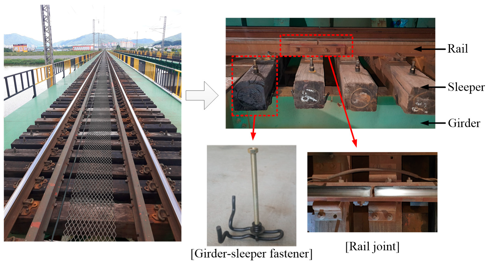
An open-deck steel plate girder bridge has been used as a railway bridge in several countries for many years. In such a bridge, since a girder and the track are connected without a deck and ballast (Figure 1), the impact and vibration at the track, generated by train passage, is directly transmitted to the bridge. As a result, frequent damage to bridge members and a high level of noise can occur. The impact and vibration level can be amplified dramatically in the presence of rail joints and cause rapid deterioration of the stiffness and strength of the track, which leads to track irregularities and damage to bridge members and bearings [1,2].
In most open-deck steel plate girder bridges, standard-length rails (about 20 m–50 m) are interconnected using rail joints and are installed on sleepers that are connected to a girder using a fastener. This girder–sleeper fastener is usually shaped like a reverse T, as shown in Figure 1, and has low and inconsistent longitudinal and lateral resistance properties. Before the ballast bridge became common, the impact and vibration problem of the open-deck steel plate girder bridge was not such a big issue. As urbanization progressed and the demand for a calm environment increased, these shortcomings have become more prominent, and open-deck steel plate girder bridges are being replaced by bridges with ballasts and decks. However, a large number of open-deck steel plate girder bridges are still being used in many countries, and, as a large cost is required to replace them with new bridges, a more economical way to solve these problems is needed. Installing CWR (Continuous Welded Rail) can provide much cheaper alternative by eliminating rail joints.
Kish et al. [3] reported that CWR can provide enhanced fatigue life of a track and better ride comfort, as well as a reduction in track maintenance costs. However, when installing CWR on a bridge, it is necessary to secure stability due to the additional axial stress of the rail caused by the track–bridge interaction (TBI). A solution for preventing the buckling of CWR, which is being practiced, is to reduce the additional axial stress due to TBI. Chaudhary et al. [4] reported that the additional rail stress of CWR induced by TBI can be reduced by using a special rail fastener, such as a ZLR (zero longitudinal restraint) rail fastener. Lee et al. [5] proposed the sliding track system to reduce additional rail stress. By applying the sliding track system to a bridge, 80–90% of the additional axial stress can be reduced without the use of special rail fasteners, such as ZLR or RLR (reduced longitudinal restraint) rail fasteners. Miri et al. [6] studied the buckling and rail break behavior of CWR on an open-deck steel truss bridge, depending on the longitudinal fastening profiles between the bridge and the track, and they proposed an optimal track–bridge fastening strategy. In the case of an open-deck steel bridge, the lateral resistance of the track is suddenly changed in the transition zones between the bridge and the embankment region if ordinary girder–sleeper fasteners (shown in Figure 1) are used. In this case, the buckling of the CWR track in the transition zone should be carefully examined in the installation of CWR [7].
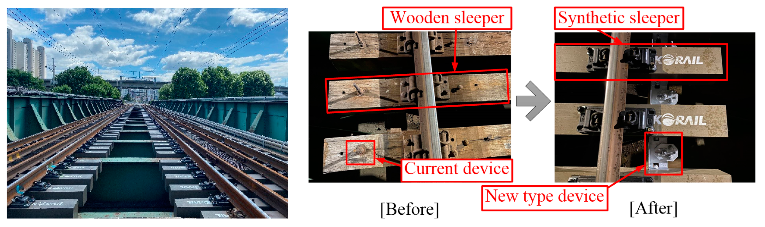
Another method to secure the stability of the CWR on an open-deck steel bridge is to develop a new girder–sleeper fastener, because it is difficult to expect adequate resistance with girder–sleeper fasteners that are currently in use. By replacing current girder–sleeper fasteners with those can provide an appropriate lateral track resistance for a CWR track, the buckling problems can be prevented. Based on this concept, a new girder-sleeper fastener has been developed recently in Korea and it has been installed on an open-deck steel bridge that is in service, as shown in Figure 2. However, the design method of such devices has not been well established.
In this study, the focus is on determining the lateral resistance requirements of a girder–sleeper fastener for installing a CWR on an open-deck steel plate girder bridge. For this purpose, two approaches, one using an existing empirical formula and the other using numerical simulations, are conducted. The numerical simulation is performed using FE models, including the track and bridge, and a series of parametric studies is conducted. The main parameters are girder length, curve radius, lateral displacement of the bridge, and the peak lateral resistance of girder–sleeper fastener. Considering the results of the two approaches, the minimum requirements that can be used in designing a new girder–sleeper fastener for CWR installation on an open-deck steel plate girder bridge is proposed.
2. Theoretical Approach
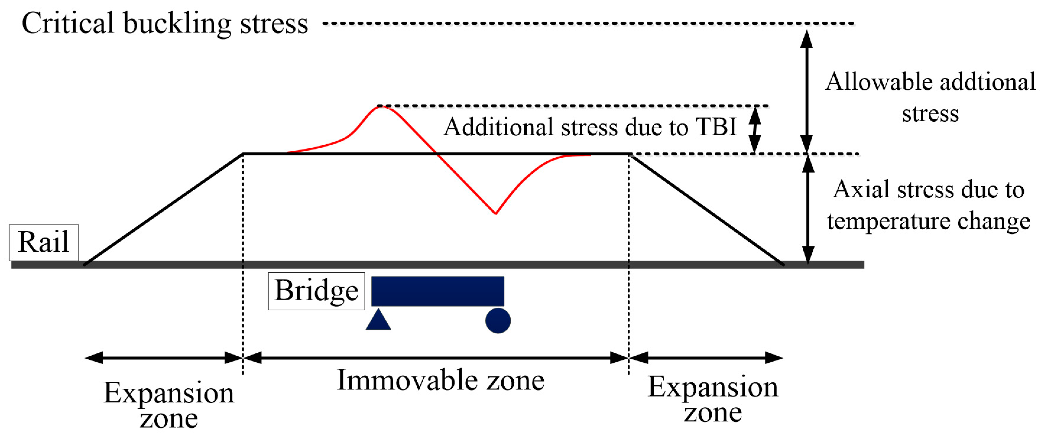
Figure 3 shows the axial stress distribution in a CWR on a bridge when the temperature rises. The stress is generated in the rail due to temperature change and ballast resistance, and the immovable zone occurs in the center of the CWR, in which the extension or contraction of the CWR is restricted. When a bridge is located in the immovable zone, additional axial stress in a CWR is generated due to TBI, as shown in Figure 3, because, unlike the CWR, the length of the bridge can be changed by temperature variations [8]. If the temperature rises excessively, buckling of the CWR occurs when the summation of the axial stresses in the CWR reaches the critical buckling stress, as illustrated in Figure 3.
Based on Figure 3, the allowable additional axial stress of the CWR track on the bridge region, fall, can be expressed as:
where fb,min is the minimum buckling stress of the CWR track, fT is the stress due to the temperature change, ΔTR. αR and ER are the thermal expansion coefficient (=1.14 × 10⁻⁵/°C) and Young’s modulus (=210,000 MPa) of the CWR, respectively.
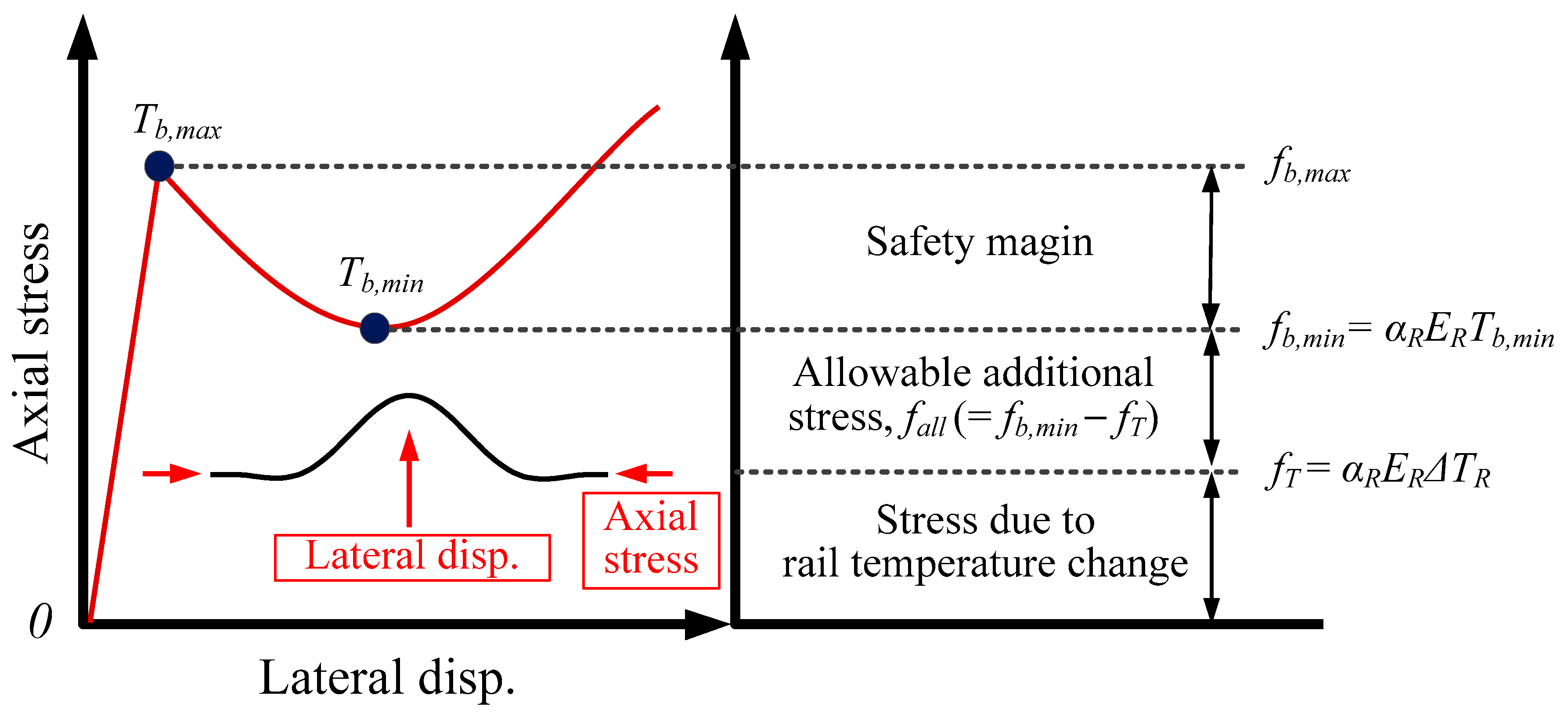
The concept of additional axial stress of the CWR in compression is shown in Figure 4. Generally, the relationship between the axial stress and lateral displacement of the rail for CWR track buckling shows a snap-through shape, and the critical buckling stress of the CWR track is defined as fb,min (refer to Figure 4). Thus, the additional axial stress of the CWR can be obtained by subtracting the stress due to temperature change, fT, from fb,min. In UIC 774-3R [9], the allowable additional axial compressive stress is specified as 72 MPa for a ballasted track with a minimum curve radius of 1500 m and a consolidated deep ballast (more than 30 cm of ballast height).
Similar to the UIC code, KR C-08080 [10], a Korean code for track design, gives allowable additional axial stress (compression) for a ballasted track, as shown in Table 1. When the curve radius is greater than 1500 m, the allowable additional axial stress is the same as that of UIC code. In addition, it can be seen that KR C-08080 provides more detailed allowable additional axial stress criteria for various curve radii.
KR C-14050 [11] provides the empirical formula to calculate the minimum buckling stress, fb,min, and fb,min can be obtained as the minimum value of:
and
where
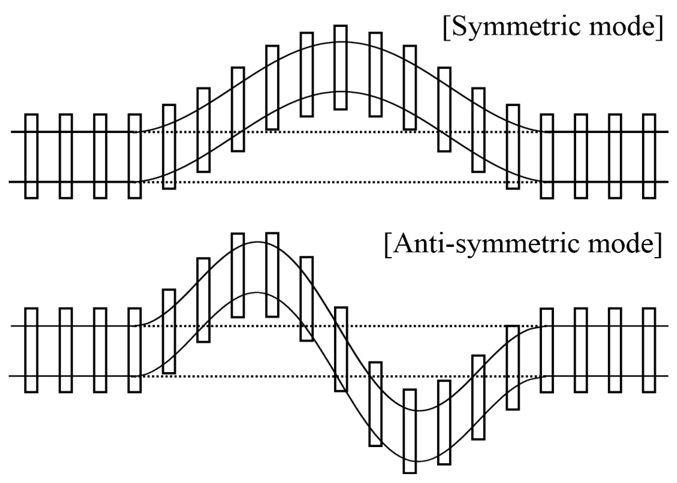
In Equation (2), fb,min1 and fb,min2 (MPa) are the minimum buckling stress of a CWR track with symmetric and anti-symmetric modes, respectively, as shown in Figure 5. IR is the bending rigidity of the rail about a weak axis (cm4), g0 is the peak ballast lateral resistance per rail (N/cm/rail), AR is the area of the rail (cm2), and R is the curve radius (m). Constant values of a, b, and c are 109, 1.04, and −0.186, respectively for a 60-kg rail.
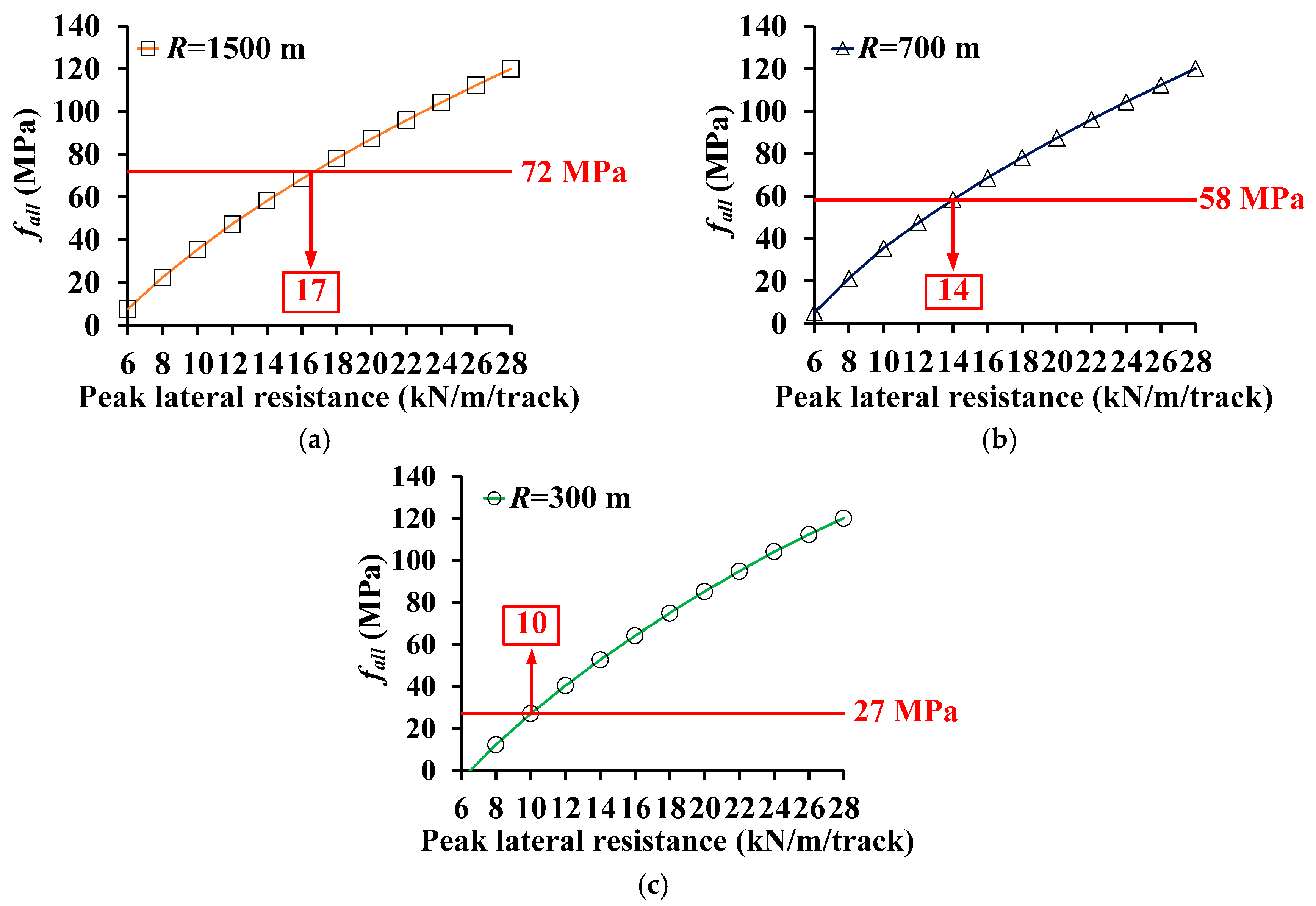
By using Equations (1) and (2), the approximate peak lateral resistance requirements of the CWR track can be obtained, as shown in Figure 6. In Figure 6, the x and y axes represents the peak lateral resistance of the CWR track and fall, respectively. Firstly, for a given curve radius (1500 m, 700 m, and 300 m), fb,min was calculated using Equation (2) for various values of the peak lateral resistance. Then, fall could be obtained using Equation (1), where ΔTR is set as 35 °C (=60 °C (the max. temp. of the rail) −25 °C (the rail laying temp.)) according to KR C-14050 [11]. UIC 60 rail is used for the calculation and IR of UIC 60 rail is 513 cm4.
From Figure 6a–c, it can be seen that the minimum peak lateral resistance requirement of girder–sleeper fastener is approximately 17 kN/m/track, 14 kN/m/track, and 10 kN/m/track for R = 1500 m, 700 m, and 300 m, respectively. These results can be utilized as reference values for the preliminary design of the fastener. However, the effect of the bridge is not considered in this result. Furthermore, in-depth CWR track buckling behavior on the open-deck steel plate girder bridge should be discussed to determine the proper lateral resistance requirements of a girder–sleeper fastener, and this appears in later sections.
3. Description of FE Model and Verification
3.1. Modeling Method
The lateral resistance requirement of a CWR track on an open-deck steel plate girder bridge is determined using FE analyses. In this study, the commercial FE analysis program ABAQUS [12] was used to perform numerical simulations.
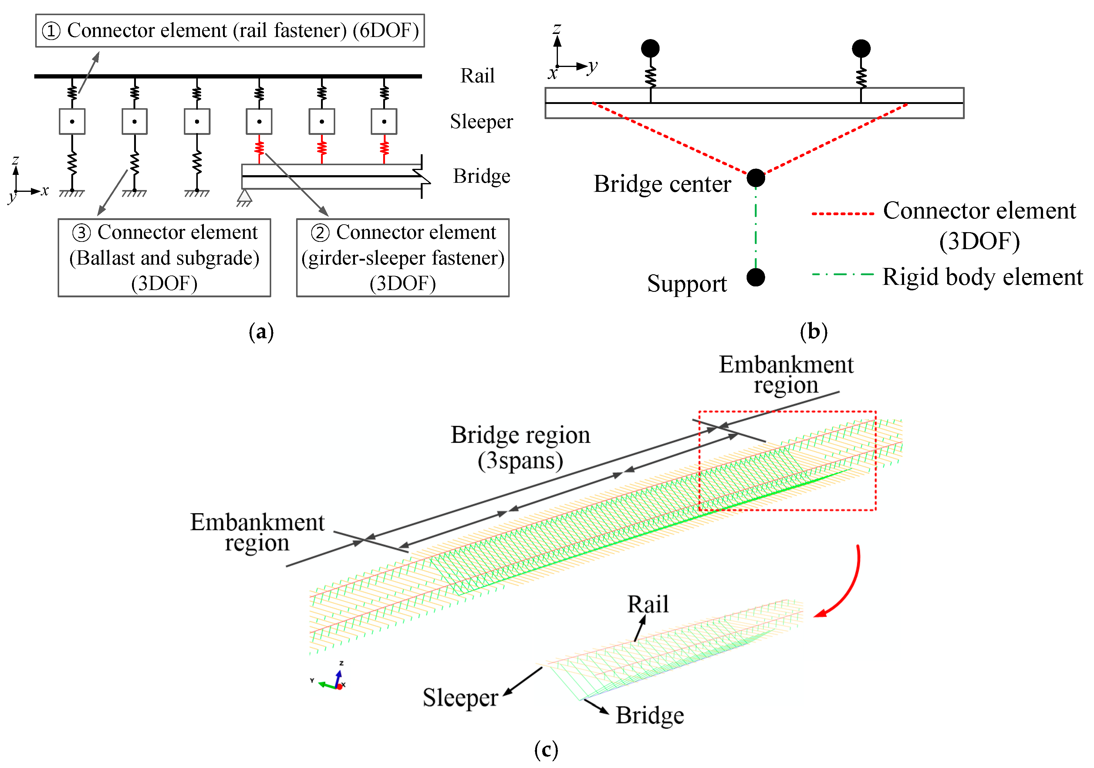
The FE model for the CWR track on the bridge is constructed based on the modeling approach of previous research [13]. The model consists of bridge and embankment regions, as shown in Figure 7. The length of the embankment region is set as a total of 200 m (100 m for each side) so that it can reflect CWR behavior. Rails, sleepers, and the bridge members are modeled using 3D beam elements. The connection between the rail and the sleeper, i.e., the rail fastener, is modeled by a connector element, CONN3D2, which is provided by ABAQUS [12]. This connector element can simulate elastic and plastic behaviors between two nodes in six directions (3 translations and 3 rotations). For the track on the embankment region, the ballast and subgrade are modeled using CONN3D2, considering only translations in three directions (no rotations). Similarly, for the girder–sleeper fastener in the bridge region, only the translational degrees of freedom are considered and modeled by CONN3D2.
UIC 60 rail was used in the analysis. The area and the moment of inertia in the strong and weak axes of the UIC 60 rail were 76.86 cm2, 3055 cm4 and 513 cm4, respectively. The elastic modulus, thermal expansion coefficient, and Poisson’s ratio of the rail were 210,000 MPa, 1.14 × 10⁻⁵/°C, and 0.3, respectively.
For the rail fastener, the properties shown in Table 2 were used [14,15,16]. In Table 2, Kx,f, Ky,f, and Kz,f are the translational stiffness of the rail fastener in the x, y, and z directions, respectively. Rx,f, Ry,f, and Rz,f represent the corresponding rotational stiffness of the rail fastener in each direction. Note that the directions can be recognized in Figure 7. In KRS TR 0014-20R [14], the minimum peak longitudinal resistance of the rail fastener is defined as 7 kN with an elastic limit of 0.5 mm. Thus, Kx,f is calculated as 1.4 × 10⁷ N/m, as shown in Table 2. Note that the perfect elasto-plastic behavior of the rail fastener is used only for the longitudinal direction, while the elastic behavior is assumed for the other degrees of freedom. The snap-through buckling behavior of the CWR mainly depends on the lateral behavior of the ballast (or the girder–sleeper fastener in this study). The longitudinal material behavior of the rail fastener is not an important factor for the buckling analysis of the CWR track, and the elastic behavior of rail fastener is usually used for analysis [3]. However, it is the main parameter for track–bridge interaction (TBI) analysis and the perfect elasto-plastic behavior of the rail fastener is considered in this study for further applications of this model to TBI analysis.
In the case of the girder–sleeper fastener, the vertical stiffness was infinite since the sleeper was connected to the girder directly. For the longitudinal and lateral directions, the perfect elasto-plastic behavior was applied. To identify the influence on the buckling characteristics of the CWR track, the peak lateral resistance, which is the main parameter of this study, was varied from 14 kN/m/track to 22 kN/m/track with 2 mm of elastic limit, while the peak longitudinal resistance was fixed as 20 kN/m/track with 2 mm of elastic limit, which is the normal peak longitudinal resistance of the ballasted track for a high-speed train line.
The embankment region of the analysis model is assumed as a normal ballasted track in which the typical values for peak longitudinal and lateral resistance (20 kN/m/track and 18 kN/m/track, respectively) with 2 mm of elastic limit were applied. For the vertical direction, the elastic behavior was assumed and a vertical stiffness of 98.9 N/mm/sleeper was used considering the typical stiffnesses of the ballast (=131.4 N/mm/sleeper) and the subgrade (=400 N/mm/sleeper).
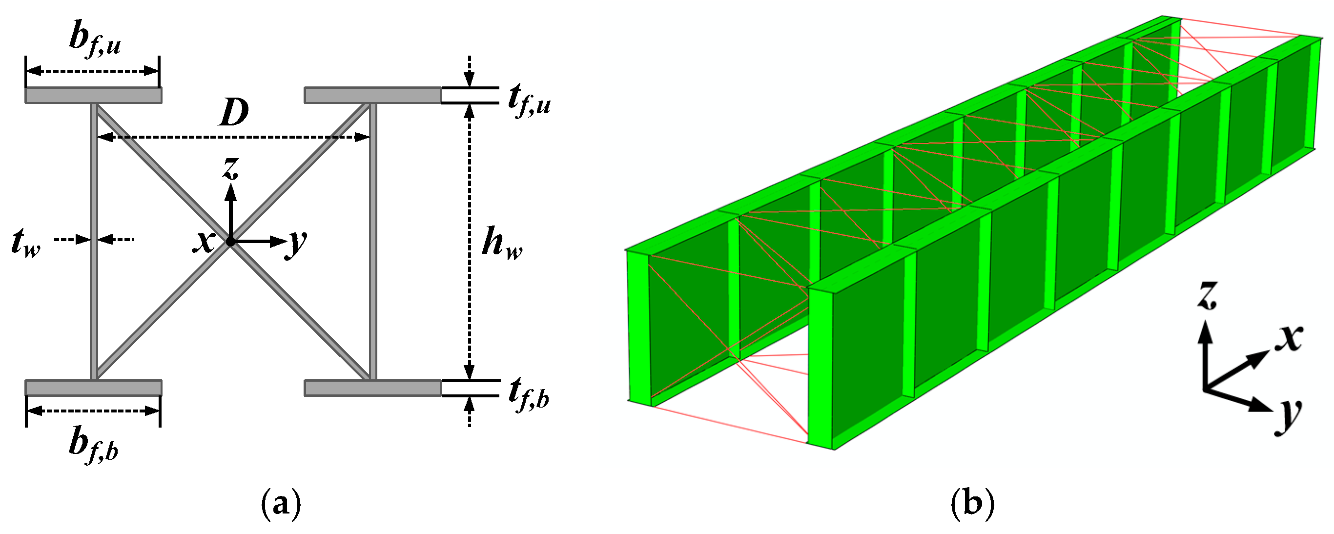
In this study, the bridge was modeled with a classic beam element. The dimensions for the section of the open-deck steel plate girder bridge are shown in Figure 8a and Table 3. Note that, in Korea, since the span length of an open-deck steel plate girder bridge varies between 9 m and 30 m, bridge sections for three different span lengths (9 m, 15.2 m, and 30 m) were selected from the existing bridge.
A typical 3D FE model is depicted in Figure 8b. Using the 3D analysis model, the section properties for the equivalent beam model are shown in Figure 7 and were derived using unit load analysis. The derived section properties, including axial rigidity (EA), in-plane and out-of-plane bending rigidity (EIy and EIz), and torsional rigidity (GJ), are summarized in Table 4.
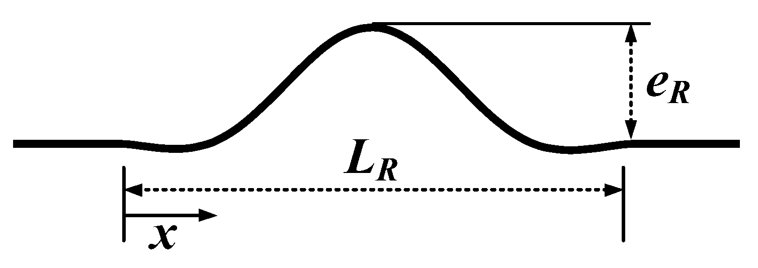
To invoke the buckling of a CWR track in the numerical simulation, the initial imperfection of the rail has to be included in the FE model. In this study, the shape of the imperfection is assumed to be a half-sine curve, as shown in Figure 9, with a maximum magnitude, eR, of 17 mm for a rail length, LR, of 10 m. Note that the maximum magnitude of the imperfection was set based on rail maintenance practices in Korea [17], where the maximum misalignment in a normal track is provided as 17 mm for a rail length of 10 m. Thus, the initial imperfection of the rail, δR, can be expressed as:
In general, the open-deck steel plate girder bridge has a low lateral bending stiffness compared with other types of railway bridges, and a considerable lateral vibration can occur when a train passes through. Since the track is directly attached to the girder and the lateral displacement of the girder can amplify the initial imperfection of the rail, the lateral displacement occurring through the lateral vibration can reduce the buckling stress of the CWR track. For this reason, the lateral displacement of the girder is considered in the analysis. The lateral displacement of the girder, δG, is defined as:
where LG is the length of the girder. eG is the maximum lateral displacement of the girder at the mid-span. eG of 0, LG/1500, and LG/1000 are considered in the analysis.
The non-linear analysis is conducted by increasing the temperature of the rail. Then, the axial stress of the CWR can be obtained by converting the rail temperature to the stress (refer to Equation (1)). In order to simulate the snap-through buckling curve of a CWR track, the Riks method was applied. The Riks method is used for the simulation of buckling or collapse behaviors, where the load–displacement response shows a negative stiffness and the structure must release strain energy to remain in equilibrium [12].
In the case of a curved track, the connector elements for the rail fastener and the girder–sleeper fastener have to be located in longitudinal, tangential, and radial direction of the curved track. For this, a cylindrical local coordinate system was introduced for the curved track.
3.2. Verification
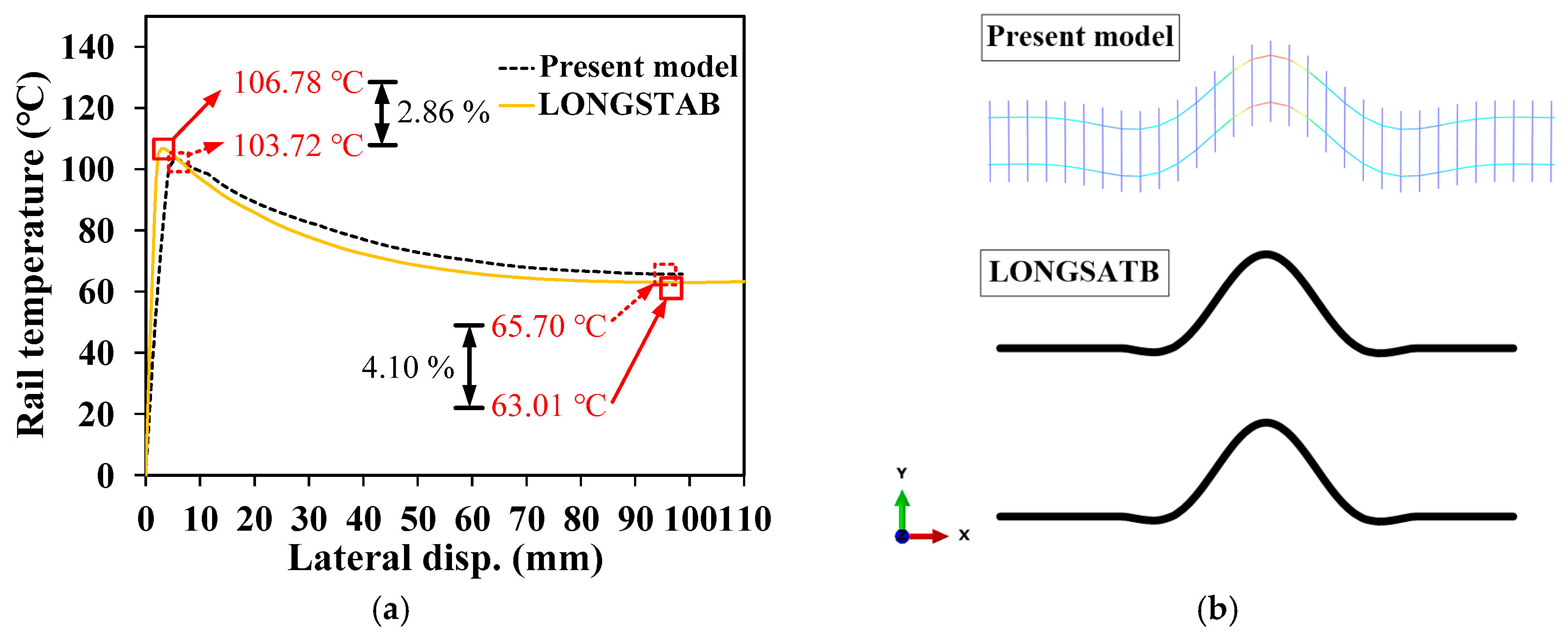
The FE analysis approach of this study was verified by comparing with the results of the LONGSTAB program [18], which has been widely used in analyzing track stability. Since the LONGSTAB program can not consider a bridge, an identical CWR track model, but without a bridge, is utilized in the comparison. The comparison results are shown in Figure 10. In Figure 10, the x and y axes represent the lateral displacement of the rail and applied temperature to the rail, respectively. From the results, the maximum and the minimum buckling temperatures are similar to each other, with less than 5% difference. Thus, it can be known that the modeling approach of this study is proper to analyze the CWR track buckling. In addition, it can be found that a critical temperature corresponding to fb,min is 65.7 °C, which is close to 72 MPa (which is the value specified in UIC and Korean codes) of allowable additional axial compressive stress, fall, where ΔTR is set as 35 °C.
4. Parametric Study
4.1. Parameters
A parametric study was conducted to determine the minimum requirement of the girder–sleeper fastener to install a CWR track on an open-deck steel plate girder bridge. The main parameters were the span length of the girder, curve radius, peak lateral resistance of the girder–sleeper fastener, and the lateral displacement of the girder.
The details of the parameters are shown in Table 5. The three cases (span lengths of 9 m, 15.2 m, and 30 m) were considered. In the case of curve radius, 300 m, 700 m, and 1500 m were adopted. Note that if the curve radius is larger than 1500 m, the track buckling behavior is almost same with straight track where R = ∞ [9]. The peak lateral resistance of the girder–sleeper fastener varied from 14 kN/m/track to 22 kN/m/track where the elastic limit is 2 mm (5 cases). In addition, three different cases of lateral displacement of the girder (0, LG/1500, and LG/1000) were considered in the analysis. Thus, total 135 cases were analyzed.
4.2. Analysis Results
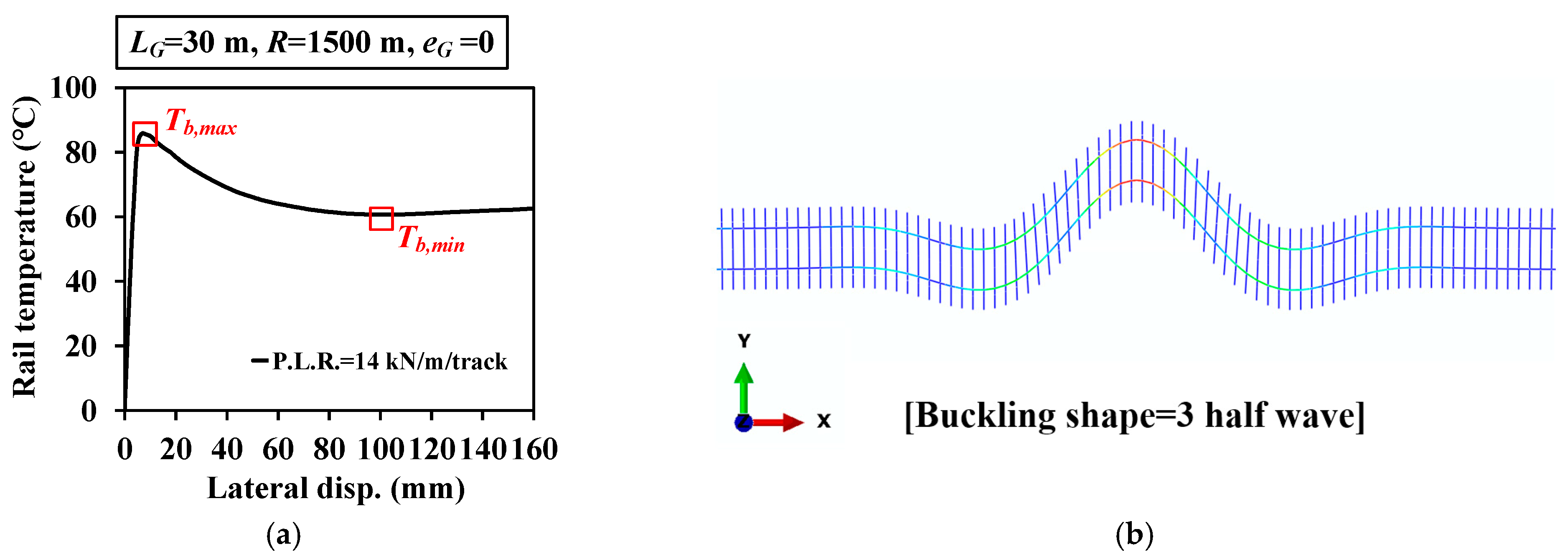
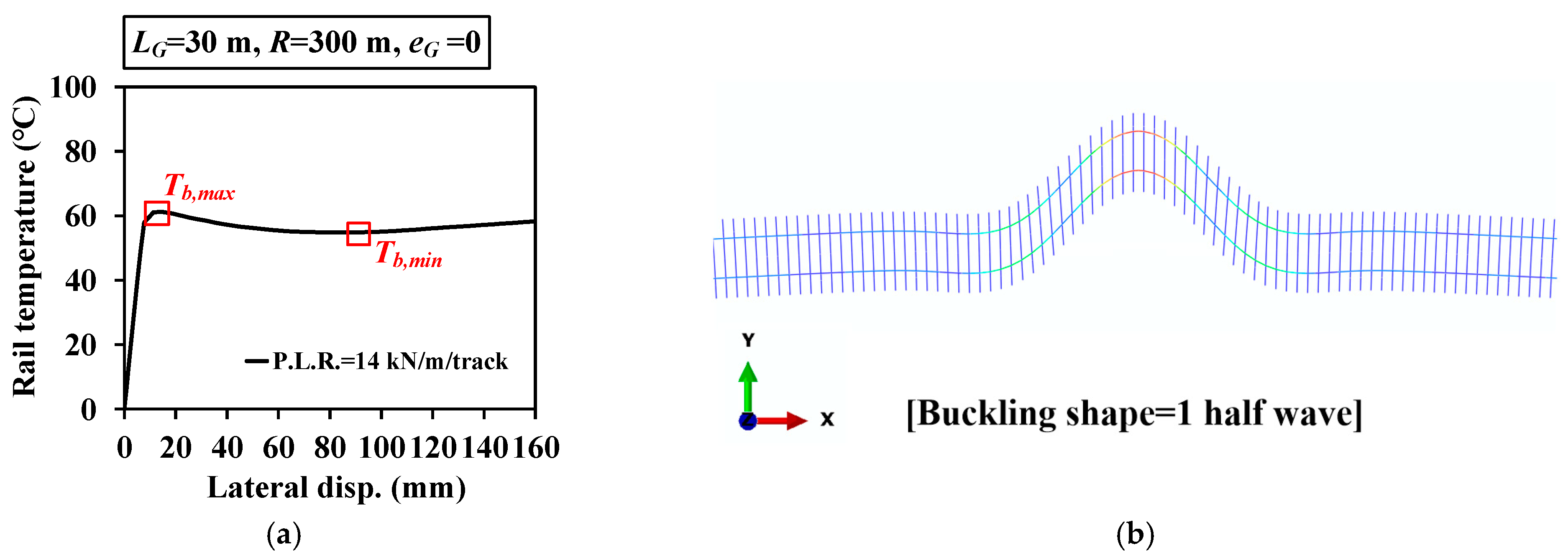
Figure 11 and Figure 12 show typical analysis results of the CWR track on ab open-deck steel plate girder bridge for R = 1500 m and R = 300 m, respectively, where PLR represents the peak lateral resistance of the girder–sleeper fastener. Note that in both figures PLR is 14 kN/m/track, span length, LG, is 30 m, and lateral displacement of girder, eG, is equal to 0.
The difference between Tb,max and Tb,min of a model with R = 1500 m is larger than that of the model with R = 300 m. This means that the CWR buckling behavior is changed from snap-through buckling to progressive buckling by decreasing the curve radius. Generally, if Tb,max − Tb,min is large, the track is categorized into a “strong track” while the track becomes “weak”to the buckling with decreasing the value of Tb,max − Tb,min. The similar behaviors are also observed in this analysis. Furthermore, it can be seen that the buckling shape is changed with decreasing the curve radius, from 3 half waves to 1 half wave, as shown in Figure 11b and Figure 12b.
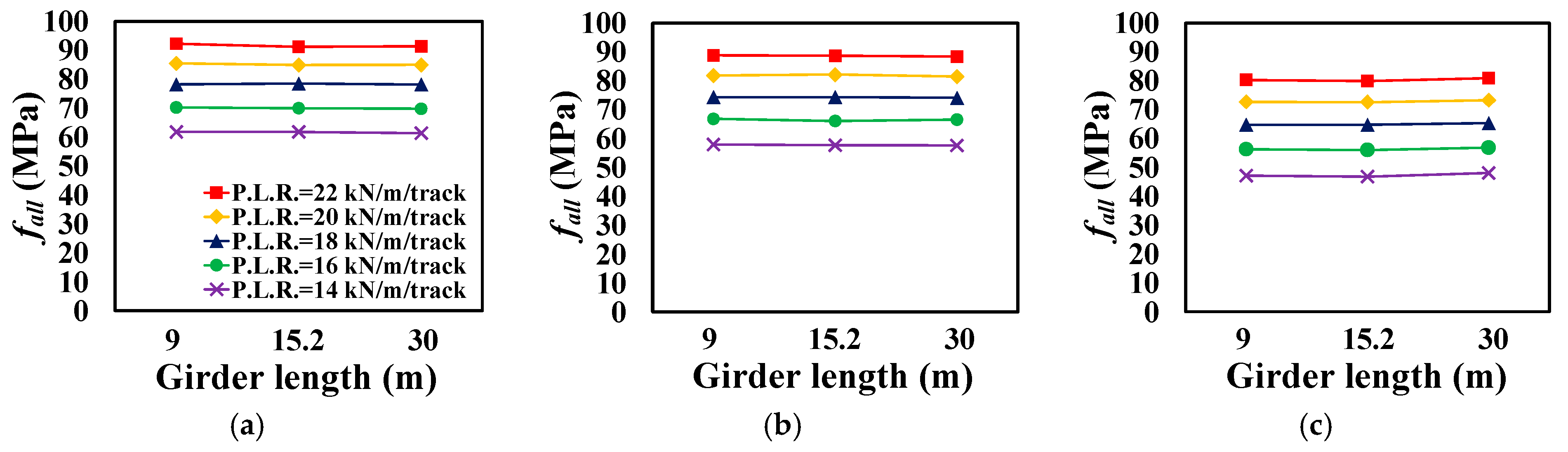
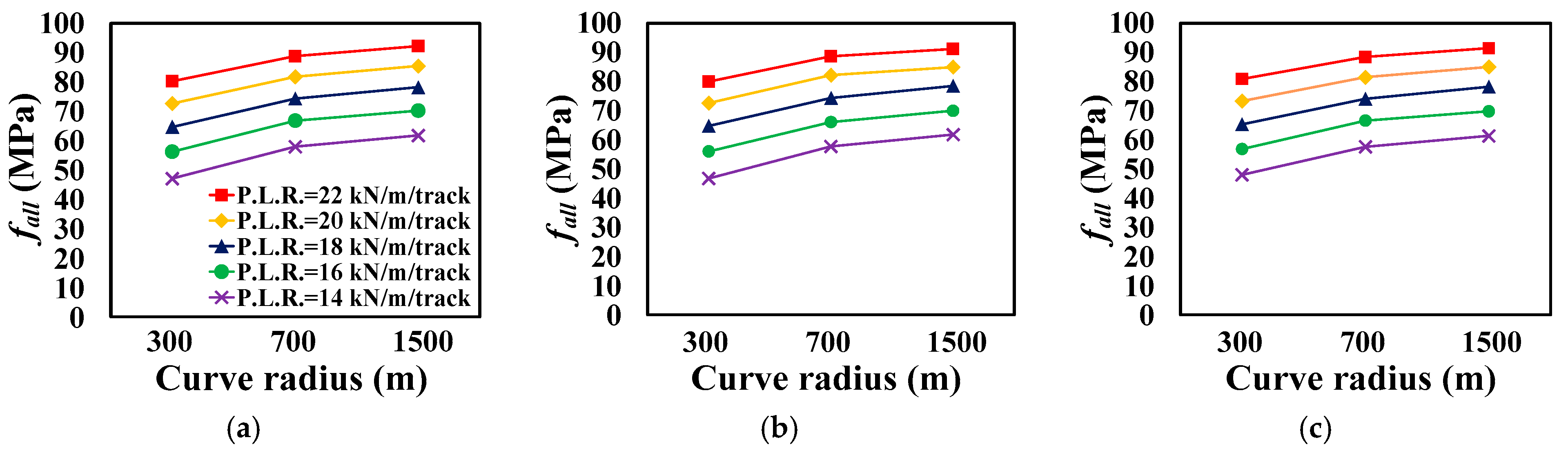
If Tb,max − Tb,min is smaller than 5 °C, Tb,min has to be adjusted as Tb,min − 5 °C for the calculation of critical buckling stress, fb,min, according to UIC code [19] and this method is also used in this study to calculate fb,min. After fb,min is obtained from the analysis, allowable additional axial compressive stress, fall, can be calculated using Equation (1), where ΔTR is set as 35 °C. fall is plotted in Figure 13, Figure 14 and Figure 15 to examine the effect of girder length, curve radius, and lateral displacement of the girder on fall, respectively.
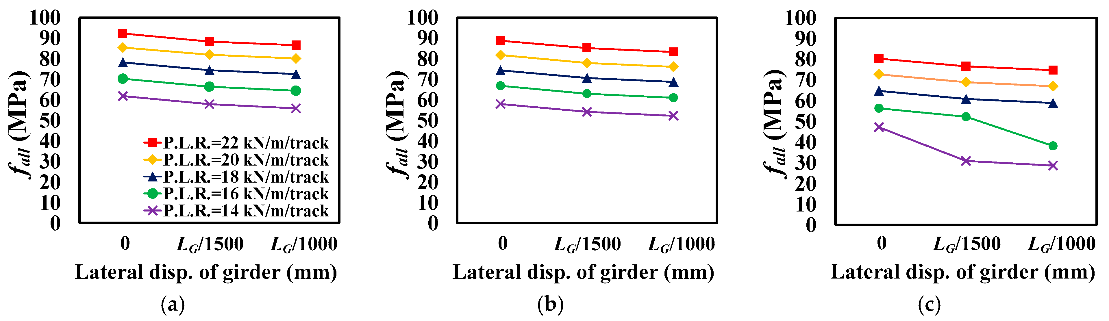
From Figure 13, Figure 14 and Figure 15, it can be found that fall increases with increasing PLR. In Figure 13, the x and y axes denote girder length and fall, respectively. It can be seen that the variation of fall with girder length is negligible for all considered girder lengths, as shown in Figure 13a–c. In the case of the curve radius, fall decreases with decreasing curve radius, R (refer to Figure 14). The maximum reduction of fall is almost 49% by decreasing R from 1500 m to 300 m. This case is the model with PLR = 14 kN/m/track, eG = LG/1000, and LG = 9 m. Figure 15 shows the effect of the lateral displacement of the girder, eG. By increasing eG, fall is decreased. The average and the maximum reduction of fall are 5% and 39%, respectively. The maximum reduction is observed among R = 300 m models and the effect of eG becomes more critical with decreasing R. In summary, it can be observed that the effect of girder length is negligibly small. On the other hand, the effect of the curve radius and lateral displacement of the girder should be considered to determine fall, since fall is reduced by 49% and 39% due to the effect of R and eG, respectively.
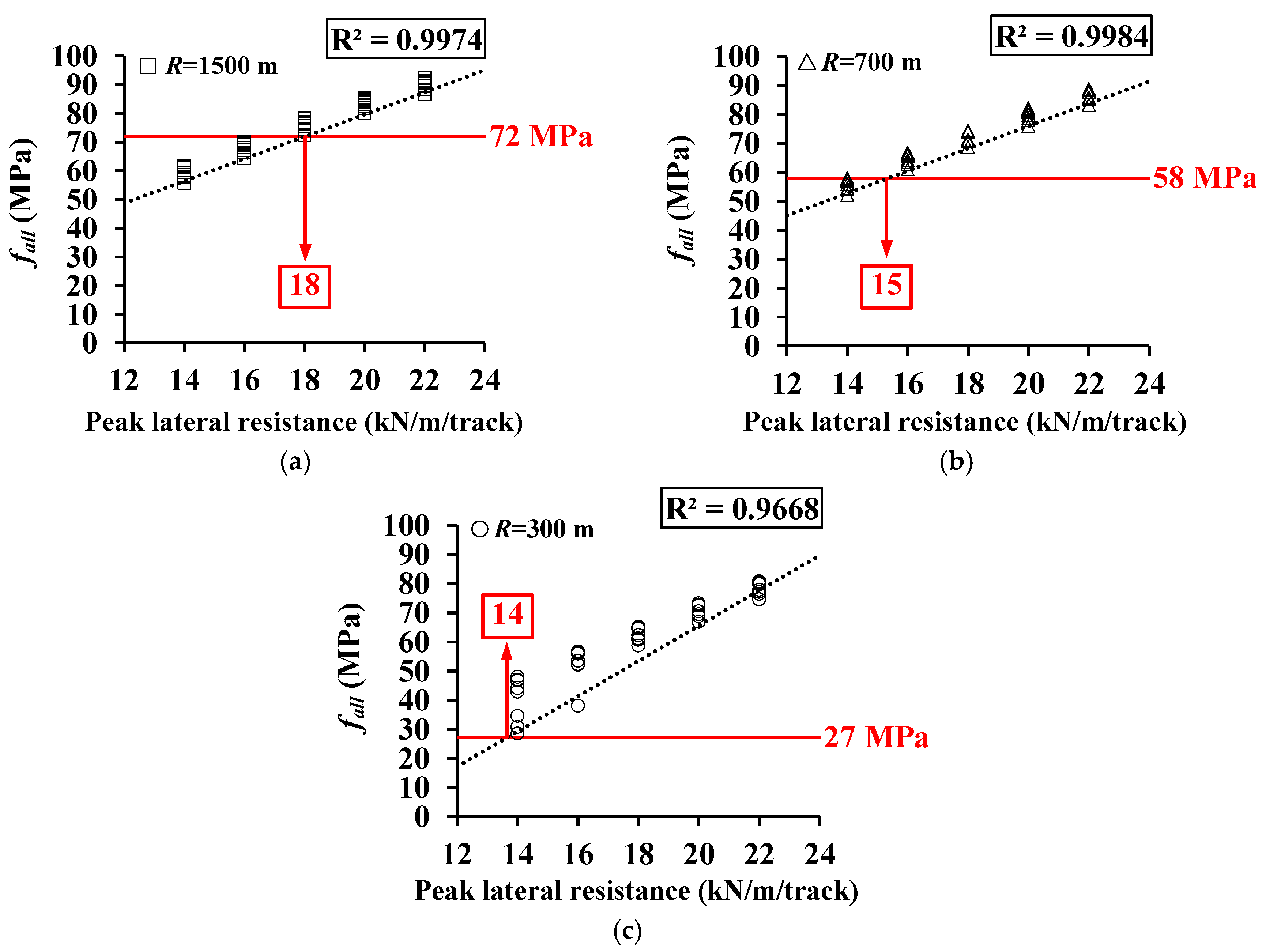
All the analysis results are plotted as a function of PLR, as shown in Figure 16a–c. From these figures, it can be seen that fall is almost linearly increased with increasing PLR. For each curve radius, the linear regressions are performed and R2 is larger than 0.97. From these regression results, the minimum PLR requirement for each curve radius is obtained, as shown in Figure 16a–c. It should be noted that target fall values are shown in Table 1, and they are 72 MPa, 58 MPa, and 27 MPa for R = 1500 m, R = 700 m, and R = 300 m, respectively. From the results, the minimum PLR requirements for R = 1500 m, R = 700 m, and R = 300 m are 18 kN/m/track, 15 kN/m/track, and 14 kN/m/track, respectively. These values are approximately 6% and 7% greater than those from the theoretical approach shown in Section 2 for R = 1500 m and R = 700 m, respectively. In the case of R = 300 m, the minimum PLR requirement obtained from the FE analysis is 40% greater than that from theoretical approach. This is because the effect of the bridge not considered in the theoretical approach is much greater at very small curve radius.
In the case of ballasted track, CWR track buckling is mainly affected by the ballast properties [20] and the Track Maintenance Guideline in Korea [17] specifies the minimum PLR of the ballast as 10 kN/m/track and 18 kN/m/track for conventional and high-speed railway, respectively, to prevent the buckling of CWR track. From the analysis results, the minimum 18 kN/m/track of PLR is needed for CWR track with R = 1500 m on the open-deck steel plate girder bridge, which is the same value for the ballasted track in high-speed railway.
5. Conclusions
In this paper, the minimum requirement of peak lateral resistance of a CWR track on an open-deck steel plate girder bridge, which can be utilized in developing girder–sleeper fasteners, is studied.
Firstly, the minimum peak lateral resistance of the fastener is derived from the theoretical approach. From the results, 17 kN/m/track, 14 kN/m/track, and 10 kN/m/track of peak lateral resistance are needed to satisfy the allowable additional axial compressive stress criteria for R = 1500 m, R = 700 m, and R = 300 m, respectively. However, the effects of the bridge cannot be considered in the theoretical approach. Thus, FE analysis is conducted, including the bridge. A series of parametric studies is performed via FE analyses. The main parameters are peak lateral resistance of the girder–sleeper fastener, curve radius, girder length, and lateral displacement of the girder. From the analysis results, it can be found that the effect of the girder length is negligible.
Secondly, the allowable additional axial compressive stress is decreased with decreasing the curve radius and increasing the lateral displacement of the girder. The maximum reductions of the allowable additional axial compressive stress are approximately 49% and 39% by the effect of curve radius and the lateral displacement of the girder, respectively, for the considered models in this study.
Finally, the minimum peak lateral resistance of the fastener is obtained as 18 kN/m/track, 15 kN/m/track, and 14 kN/m/track for R = 1500 m, R = 700 m, and R = 300 m, respectively. These values are 6% to 40% greater than those from the theoretical approach. From this result, it can be observed that the effect of the bridge not being considered in the theoretical approach is much greater at a very small curve radius.
The results of this study can be used in providing relevant provisions of design codes, as well as developing a new girder–sleeper fastener device for CWR installation on an open-deck steel plate girder bridge. However, since the results in this study are solely based on theoretical and numerical analyses, verification studies based on experiment or field monitoring data are needed in the future. By introducing a continuous rail monitoring system, the derailment risk due to the buckling of a CWR can be effectively reduced [21], and measurement data for verifying the performance of the girder–sleeper fastening device can be obtained.
Author Contributions
Methodology, J.M., S.C. and H.-D.L.; investigation, H.-D.L. and J.M.; writing—original draft preparation, H.-D.L.; writing—review and editing, J.M. and S.C.; project administration, J.M. All authors have read and agreed to the published version of the manuscript.
Funding
This research was supported by a grant (20RTRP-B137949-04) from Research Program funded by Ministry of Land, Infrastructure and Transport of Korean government.
Institutional Review Board Statement
Not applicable.
Informed Consent Statement
Not applicable.
Data Availability Statement
Not applicable.
Conflicts of Interest
The authors declare no conflict of interest.
References
- Cai, W.; Wen, Z.; Jin, X.; Zhai, W. Dynamic stress analysis of rail joint with height difference defect using finite element method. Eng. Fail. Anal. 2007, 14, 1488–1499. [Google Scholar] [CrossRef]
- Chaboki, A. Assessment and Maintenance of Open Deck Railway Bridges. In Proceedings of the 9th Australian Small Bridges Conference, Gold Coast, QLD, Australia, 1–2 April 2019. [Google Scholar]
- Kish, A.; Samavedam, G. Track Buckling Prevention: Theory, Safety Concepts, and Applications (No. DOT/FRA/ORD-13/16); John, A., Ed.; Volpe National Transportation Systems Center: Washington, DC, USA, 2013. [Google Scholar]
- Chaudhary, K.R.; Sinha, A.N. A Study of Various Methods Adopted by World Railways to Continue LWR over Bridges. 1939. Available online: https://www.scribd.com/document/71782998/LWR (accessed on 6 November 2011).
- Lee, K.C.; Jang, S.Y.; Jung, D.K.; Byun, H.K.; Park, H.K.; Yang, T.S. Rail-Structure Interaction Analysis of Sliding Slab Track on Bridge. In Proceedings of the 2015 Joint Rail Conference, San Jose, CA, USA, 23–26 March 2015. [Google Scholar]
- Miri, A.; Thambiratnam, D.; Chan, T. Thermal challenges of replacing jointed rails with CWR on steel railway bridges. J. Constr. Steel Res. 2021, 181, 106627. [Google Scholar] [CrossRef]
- Miri, A.; Thambiratnam, D.; Weston, B.; Chan, T.H.T.; Dhanasekar, M. Lateral stability of CWR tracks in transition zones of open-deck steel bridges. Structures 2021, 33, 897–915. [Google Scholar] [CrossRef]
- Esveld, C. Modern Railway Track, 2nd ed.; MRT-Production: Delft, The Netherlands, 2001. [Google Scholar]
- International Union of Railway. UIC 774-3-R: Track/Bridge Interaction-Recommendation for Calculations, 2nd ed.; UIC International Union of Railways: Paris, France, 2001. [Google Scholar]
- Korea Rail Network Authority. KR C-08080. Analysis of Longitudinal Track-Bridge Interaction, Design Guidelines and Handbook; Korea Rail Network Authority: Seoul, Korea, 2017. (In Korean) [Google Scholar]
- Korea Rail Network Authority. KR C-14050. Continuous Welded Rail, Railway, Design Guidelines and Handbook; Korea Rail Network Authority: Seoul, Korea, 2016. (In Korean) [Google Scholar]
- Dassault Systèmes. Abaqus 2020 Analysis User‘s Manual; Dassault Systèmes: Vélizy-Villacoublay, France, 2020. [Google Scholar]
- Yun, K.M.; Park, B.H.; Bae, H.U.; Lim, N.H. Suggestion for Allowable Additional Compressive Stress Based on Track Conditions. J. Rail Rapid Transit. 2018, 235, 1309–1325. [Google Scholar] [CrossRef]
- Korean Railway Standards. KRS TR 0014-20R. In Rail Fastening System; Railway Industry Information Center: Seoul, Korea, 2020. (In Korean) [Google Scholar]
- Lim, N.H.; Han, S.Y.; Han, T.H.; Kang, Y.J. Parametric Study on Stability of Continuous Welded Rail Track-Ballast Resistance and Track Irregularity. Int. J. Steel Struct. 2008, 8, 171–181. [Google Scholar]
- Pita, A.; Teixeira, P.F.; Robuste, F. High speed and track deterioration: The role of vertical stiffness of the track. J. Rail Rapid Transit 2004, 218, 31–40. [Google Scholar] [CrossRef]
- Korea National Railway (KR). Track Maintenance Guideline; Korea National Railway: Seoul, Korea, 2020. (In Korean) [Google Scholar]
- Esveld Consulting Services. LONGSTAB Theoretical Manual - Computer Program for the Analysis of Track Stability and Longitudinal Forces. Available online: http://www.esveld.com/Download/SOFTWARE/LONGSTAB/LONGSTAB_theoretical_manual.pdf (accessed on 25 January 2021).
- International Union of Railway. UIC 720-R. Laying and Maintenance of CWR Track, 2nd ed.; UIC International Union of Railways: Paris, France, 2005. [Google Scholar]
- Khatibi, F.; Esmaeili, M.; Mohammadzadeh, S. Numerical investigation into the effect of ballast properties on buckling of continuously welded rail (CWR). J. Rail Rapid Transit 2020. [Google Scholar] [CrossRef]
- Consilvio, A.; Iorani, M.; Iovane, V.; Sciutto, M.; Sciutto, G. Real-time monitoring of the longitudinal strain of Continuous Welded Rail for safety improvement. J. Rail Rapid Transit 2020, 234, 1238–1252. [Google Scholar] [CrossRef]
Figure 1.
Example of open-deck steel plate girder bridge.

Figure 2.
Application example of new girder–sleeper fastener device for a CWR track on an open-deck steel plate girder bridge in Korea.
Figure 2.
Application example of new girder–sleeper fastener device for a CWR track on an open-deck steel plate girder bridge in Korea.

Figure 3.
Axial force distribution of a CWR track on a bridge.

Figure 4.
Concept of additional axial stress (compression) calculation.

Figure 5.
Track buckling shape.

Figure 6.
Theoretical evaluation of the min. lateral resistance: (a) R = 1500 m; (b) R = 700 m; and (c) R = 300 m.
Figure 6.
Theoretical evaluation of the min. lateral resistance: (a) R = 1500 m; (b) R = 700 m; and (c) R = 300 m.

Figure 7.
Schematic view of FE model: (a) side view; (b) cross-section; and (c) example of FE model.
Figure 7.
Schematic view of FE model: (a) side view; (b) cross-section; and (c) example of FE model.

Figure 8.
Open-deck steel plate girder bridge: (a) section dimensions and (b) 3D modeling.

Figure 9.
Imperfection of the rail.

Figure 10.
Comparison results with LONGSTAB (track on the embankment region): (a) rail temp. vs. lateral disp.; (b) comparison of buckling shape.
Figure 10.
Comparison results with LONGSTAB (track on the embankment region): (a) rail temp. vs. lateral disp.; (b) comparison of buckling shape.

Figure 11.
Analysis results (R = 1500 m): (a) rail temp. vs. lateral disp.; and (b) buckling shape.

Figure 12.
Analysis results (R = 300 m): (a) rail temp. vs. lateral disp.; and (b) buckling shape.

Figure 13.
Effect of girder length (eG = 0): (a) R = 1500 m; (b) R = 700 m; and (c) R = 300 m.

Figure 14.
Effect of curve radius (eG = 0): (a) LG = 9 m; (b) LG = 15.2 m; and (c) LG = 30 m.

Figure 15.
Effect of lateral displacement of girder (LG = 9 m): (a) R = 1500 m; (b) R = 700 m; and (c) R = 300 m.
Figure 15.
Effect of lateral displacement of girder (LG = 9 m): (a) R = 1500 m; (b) R = 700 m; and (c) R = 300 m.

Figure 16.
fall vs. P.L.R.: (a) R = 1500 m; (b) R = 700 m; and (c) R = 300 m.


Table 1.
Allowable additional stress standard according to a ballasted track (KR code).
| Curve Radius, R (m) | Allowable Additional Stress (Compression, MPa) |
|---|---|
| R ≥ 1500 | 72 |
| R ≥ 700 | 58 |
| R ≥ 600 | 54 |
| R ≥ 300 | 27 |
Table 2.
Rail fastener properties.
| Stiffness | Value | References | Remark |
|---|---|---|---|
| Kx,f (N/m) | 1.4 × 10⁷ | KRS TR 0014-20R [14] | Perfect elasto-plastic behavior with 7 kN of peak resistance |
| Ky,f (N/m) | 2.6 × 10⁷ | Lim et al. [15] | Elastic behavior |
| Kz,f (N/m) | 8.0 × 10⁷ | Pita et al. [16] | Elastic behavior |
| Rx,f,Ry,f, and Rz,f (N·m/rad) | 6.0 × 10⁴ | Lim et al. [15] | Elastic behavior |
Table 3.
Dimensions of a typical open-deck plate girder bridge.
| Span Length (m) | D (m) | hw (mm) | tw (mm) | bf (mm) | tf (mm) | ||
|---|---|---|---|---|---|---|---|
| bf,u | bf,b | tf,u | tf,b | ||||
| 9 | 1.6 | 1170 | 10 | 250 | 250 | 30 | 30 |
| 15.2 | 1.8 | 1629 | 12 | 360 | 360 | 34 | 34 |
| 30 | 2.0 | 2548 | 12 | 480 | 560 | 38 | 40 |
Table 4.
Section properties of open-deck steel plate girder bridge calculated by 3D FE analysis.
| Span Length (m) | EA (kN) | EIy (kN·m2) | EIz (kN·m2) | GJ (kN·m2) |
|---|---|---|---|---|
| 9 | 1.15 × 10⁷ | 2.76 × 10⁶ | 7.38 × 10⁶ | 3.50 × 10⁵ |
| 15.2 | 1.87 × 10⁷ | 8.42 × 10⁶ | 1.52 × 10⁷ | 8.04 × 10⁵ |
| 30 | 3.04 × 10⁷ | 3.51 × 10⁷ | 3.08 × 10⁷ | 2.38 × 10⁶ |
Table 5.
Analysis parameters.
| Parameter | Range | Remarks |
|---|---|---|
| Length of girder, LG (m) | 9, 15.2, and 30 | 3 cases |
| Curve radius, R (m) | 1500, 700, and 300 | 3 cases |
| Lateral disp. of the girder, eG | 0, LG/1500, and LG/1000 | 3 cases |
| Lateral resistance of girder-sleeper fastener, P.L.R. (kN/m/track) | 14–22 | 5 cases |
Publisher’s Note: MDPI stays neutral with regard to jurisdictional claims in published maps and institutional affiliations. |
© 2021 by the authors. Licensee MDPI, Basel, Switzerland. This article is an open access article distributed under the terms and conditions of the Creative Commons Attribution (CC BY) license (https://creativecommons.org/licenses/by/4.0/).
Share and Cite
MDPI and ACS Style
Lee, H.-D.; Choi, S.; Moon, J. Lateral Resistance Requirement of Girder-Sleeper Fastener for CWR Track on an Open-Deck Steel Plate Girder Bridge. Appl. Sci. 2021, 11, 6681. https://doi.org/10.3390/app11156681
AMA Style
Lee H-D, Choi S, Moon J. Lateral Resistance Requirement of Girder-Sleeper Fastener for CWR Track on an Open-Deck Steel Plate Girder Bridge. Applied Sciences. 2021; 11(15):6681. https://doi.org/10.3390/app11156681
Chicago/Turabian StyleLee, Hyeoung-Deok, Sanghyun Choi, and Jiho Moon. 2021. "Lateral Resistance Requirement of Girder-Sleeper Fastener for CWR Track on an Open-Deck Steel Plate Girder Bridge" Applied Sciences 11, no. 15: 6681. https://doi.org/10.3390/app11156681
Note that from the first issue of 2016, this journal uses article numbers instead of page numbers. See further details here.