
Hybrid (Oscillator-Amplifier) Free Electron Laser and New Proposals

ENEA, Fusion Physics Division, C.R. Frascati, via E. Fermi 45, I-00044 Frascati (Rome), Italy
Appl. Sci. 2021, 11(13), 5948; https://doi.org/10.3390/app11135948
Submission received: 25 May 2021
/
Revised: 22 June 2021
/
Accepted: 22 June 2021
/
Published: 26 June 2021
(This article belongs to the Special Issue Oscillator-Amplifier Free Electron Lasers an Outlook to Their Feasibility and Performances)
Abstract
:The present work analyses a hybrid free electron laser (FEL) scheme where the oscillator is based on a radiation source operating with a slow-wave guiding structure as, for instance, a Cerenkov FEL or a Smith–Purcell FEL. Such devices, often running in transverse magnetic (TM) modes, present a longitudinal electric field which can easily affect the longitudinal electrons’ velocities, inducing an energy modulation on the beam. Such a modulation, properly controlled, can induce a strong radiation emission in a magnetic undulator properly designed to operate as a radiator. General considerations will be exposed together with a practical numerical example in the far infrared region of the spectrum.
1. Introduction
Free electron lasers (FELs) are widely acknowledged as the most versatile generators of coherent electromagnetic radiation. Since the first studies in the late 1960s [1] and their “official” invention in 1977 [2], it has been clear that FELs are capable of bridging the gap between conventional electron-based sources (such as klystrons, magnetrons, travelling wave tubes) that are limited to the high frequency direction, and the lasers that, with some exceptions, generate single frequency radiation with a power that is limited by the nature of the active medium. FELs can be designed, in principle, to operate at any frequency and with a time structure and related power suitable for any kind of experiment. This kind of flexibility comes from the fact that many of the parameters involved, such as the electron energy and the magnetic field, can be adjusted with continuity. Moreover, many dynamical regimes can be exploited for FEL design; from the low-gain regime, suitable for oscillator devices [3], to the high gain regime ideal for the self-amplified spontaneous emission (SASE) scheme [4]. Furthermore, FEL offers significant potential options to combine different schemes in sequence in order to increase the performances of some specific features without overly stressing the project parameters. One of the most relevant FEL structures arrangements, among others, is a modulator at a synchronous frequency followed by a frequency multiplier that exploits the harmonic content in the modulated beam [5,6]. Such an arrangement may be reproduced several times, creating a kind of cascade [7] that results in final beam degradation.
This study presents one of the possible arrangements based on a Cerenkov FEL oscillator as a modulator and a magnetic undulator as a radiator: this solution can be considered a hybrid FEL scheme device [8]. The reason why the term hybrid can be ascribed to such a scheme is not only due to the fact that the modulator and radiator present two different mechanisms of radiation generation, but mainly because in Cerenkov-like FEL devices [9] (as is the case for Smith–Purcell gratings [10]), the coupling between electrons and field is longitudinal, while the magnetic undulator induces a transverse motion to the electrons and accordingly, to the coupling. This circumstance, combined with the fact that Cerenkov (and Smith–Purcell) FELs operate with slow-wave guiding structures, has a relevant effect on the differences, for “synchronism condition” [9,11], that links the spontaneous emission wavelength with the most relevant parameters of the experiment, between Cerenkov and undulator FELs.
The paper is arranged in four sections: after the present Introduction, Section 2 is dedicated to the study of the Cerenkov-based modulator. Section 3 will introduce the hybrid system as a whole, highlighting the value of the main parameters. Section 4 will describe the effects of the modulation on the emission from a magnetic undulator exploited as a radiator; this analysis includes the ballistic effects of a variable drift space. Section 5 is devoted to final conclusions.
2. The Hybrid System
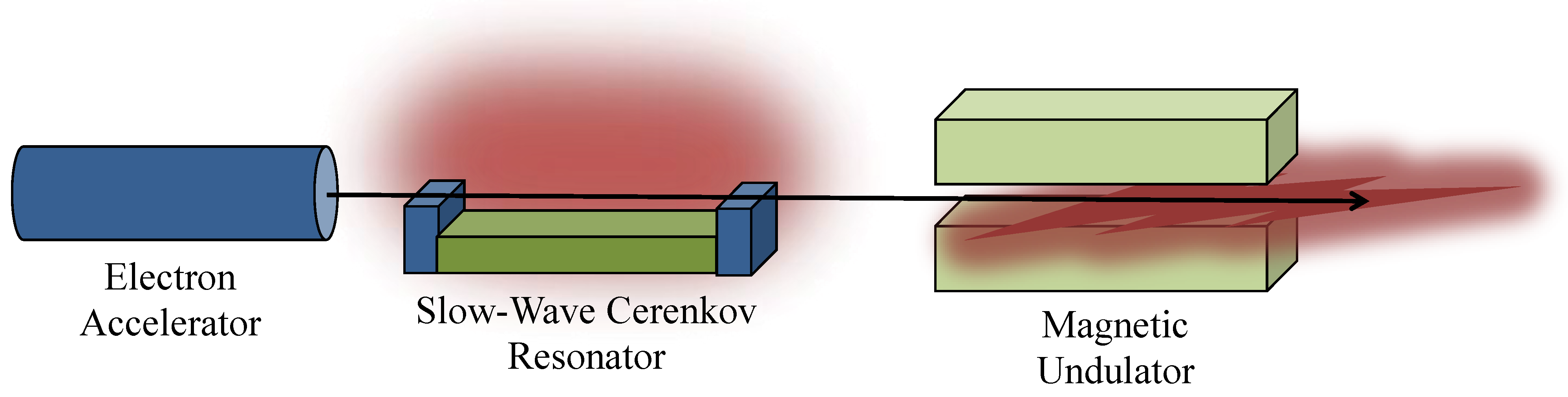
The hybrid FEL system can be assumed to be composed of three main elements: (1) an electron beam accelerator; (2) a Cerenkov slow-wave guiding structure, with an adequate radiation resonator for the saturation regime accomplishment; and lastly, (3) a magnetic undulator acting as a radiator after the velocity modulation induced by an electric field associated with the radiation stored in the Cerenkov oscillator (see Figure 1).
The first problem to face is related to the energy of the electron beam that will be common to both generating structures. As discussed in the introduction, the synchronism conditions for Cerenkov and undulator FELs are rather different and can be summarised as follows (see Refs. [9,11]), where the subscript U and C indicate the undulator and Cerenkov, respectively:
where λw indicates the undulator period, K is the undulator parameter, d is the dielectric thickness of the Cerenkov guiding structure, ε is its dielectric constant and γ is the Lorentz parameter of the electrons. All these parameters will be more deeply described in the following sections.
In order to obtain an efficient modulation of the electron beam, it is required that the radiation generated from the Cerenkov oscillator and from the Undulator radiator be “correlated”; a way to achieve this target is to obtain the condition: λU = λC/n where n = 1, 2, … specifies the harmonic number. Such a relation, with the use of Equation (1), becomes:
Equation (2) gives the value of the electron energy as a function of all the parameters involved in both the Cerenkov and undulator FELs. In order to have an idea about the numbers, we can assign some reasonable values for the involved parameters in Equation (2) such as: λw = 2.5 cm, K = 1, d = 5 μm, n = 1, ε = 5 (dielectric constant of quartz [12]) from which we obtain a result, for the electron energy, γ~10, that corresponds to a moderate relativistic energy. By inserting these values into Equation (1), we conclude that such a source would operate in the so-called far-infrared (FIR) spectral region (also called TeraHertz (THz)-region) because λU~λC~250 μm.
Another approach can be obtained by rearranging Equation (2) as follows:
from which it is possible to obtain the Cerenkov parameters values starting from the undulator FEL ones. Let us suppose we have an FEL source with λw = 2.5 cm, K = 1, γ = 20 and again working on the fundamental harmonic n = 1, Equation (3) gives: [d(ε − 1)/ε]~5·10−7 μm. Such a value may be obtained in several ways since, for instance, ε = 2 and d = 1 μm. Using all these values for the hybrid FEL parameters, we eventually obtain from Equation (1) the value for the emitted wavelength from both the elements of the hybrid FEL: λU~λC~60 μm.
3. The Cerenkov FEL Oscillator
A well-known class of waveguides is characterised by having open boundaries and the possible presence of an electromagnetic (e.m.) field outside the boundary; these guides support propagating modes called “surface waves” [13]. Dielectric films deposited over conducting plates are devices that fall into the aforementioned category; the surface waves, in this case, present an exponential behaviour, normal to the dielectric surface, that decays when moving away. Such a waveguide category is the relevant one for the realisation of the Cerenkov FEL device because the field–particle interaction occurs in the region of the space where the “evanescent” e.m. field is present.
These propagating devices present field distributions associable with transverse electric (TE) or transverse magnetic (TM) modes. The case of TM modes is more favourable for the FEL use due to the presence of a longitudinal electric field component related to them. The vector potential for the TM modes of a single slab geometry waveguide is expressed by [9,13]
where k indicates the longitudinal momentum, while q is the transverse momentum in vacuum and p is the transverse momentum in the dielectric of thickness d. All these parameters are linked by two coupled “dispersion relations” that can be deduced by the field continuity along the vacuum–dielectric interface and dielectric–conductor interface:
In order to obtain the electric and magnetic fields from Equation (4), we can adopt the Coulomb gauge () which is useful for evaluating the fields in absence of charges and currents, as for the free modes in a guiding structure. Neglecting the coupling between the electrons and the transverse electric field Ex (due to the small values of the electrons’ velocities in the x direction), we obtain for the longitudinal field:
In order to achieve the maximum field intensity, it is necessary to reach the saturation regime inside the Cerenkov waveguide resonator. The dynamics of the emission process in Cerenkov FEL has been established in the past as far as the spontaneous emission process [9,14] is concerned and with regard to the stimulated emission mechanism and the gain coefficient calculation [14,15]. Let us, therefore, consider the case discussed in Section 2 while discussing Equation (2); the relevant parameters are summarised in Table 1.
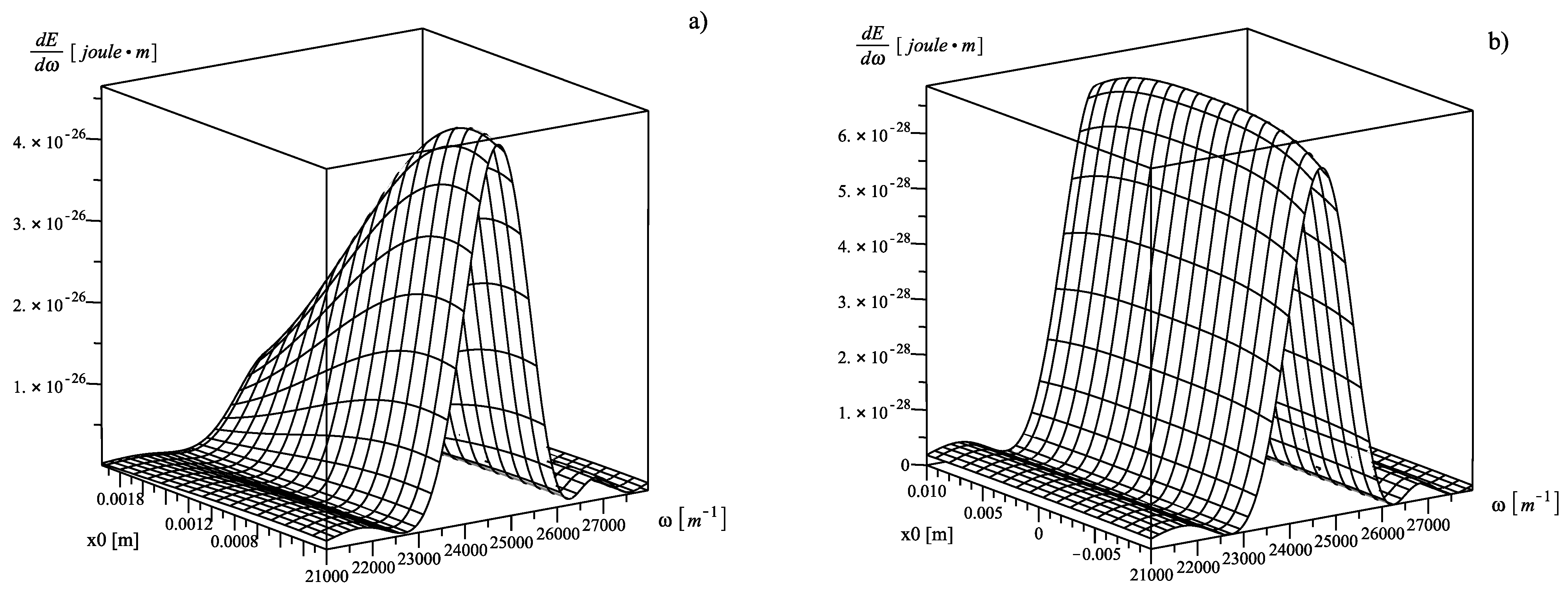
Table 1 reports the parameters for both a single slab geometry device [9] and for the double slab one [16] adequate for an operation around λC = 250 μm. The behaviour of the spontaneous emission for a single-electron beam with a transverse size of σx = 1 mm (r.m.s.), as a function of frequency and beam centroid distance from the dielectric surface, is reported in Figure 2a). The same analysis for the double slab geometry and a beam size of σx = 1 cm (r.m.s.) is reported in Figure 2b):
The one-dimensional stimulated emission process, until saturation, can be studied by means of semi-analytical techniques [17] (three-dimensional theory can be found in [18]). The saturation mechanism in free electron devices is quite similar to that occurring in conventional lasers, as has been derived by Rigrod approximately sixty years ago [19] and is also present in the theory of passive saturable absorber for laser mode-locking [20]. Two different but similar approaches can be applied; the first technique starts from the application of the Ginzburg–Landau equation to FEL systems [21] and leads to the GI(I) expression in Equation (7). The second method is based on the logistic equation approach [22] and ends up the GII(I) expression in Equation (7):
where Neq = L/(2γ2λC) ~ 7.3 represents the equivalent value of the number of undulator periods in Cerenkov FELs; ISAT~7.4·106 [W] expresses the saturation power value related to the gain of the device (conventionally, the intensity is used instead of power, however, in this case, the radiation transverse cross-section is a constant due to the presence of a waveguide, making power and intensity interchangeable); n indicates the round-trip number; IAV~17,000 A indicates the Alfven current; Γ represent the total losses in the radiation resonator; ISP expresses the spontaneous emission power of all the electrons in the bunch and integrated over the bandwidth; Ie,i refers to the intracavity equilibrium power, and finally, g0MAX indicates the maximum value of the small-gain, small-signal gain coefficient as a function of frequency [15]. The relevant parameters for the gain calculation are reported in Table 2.
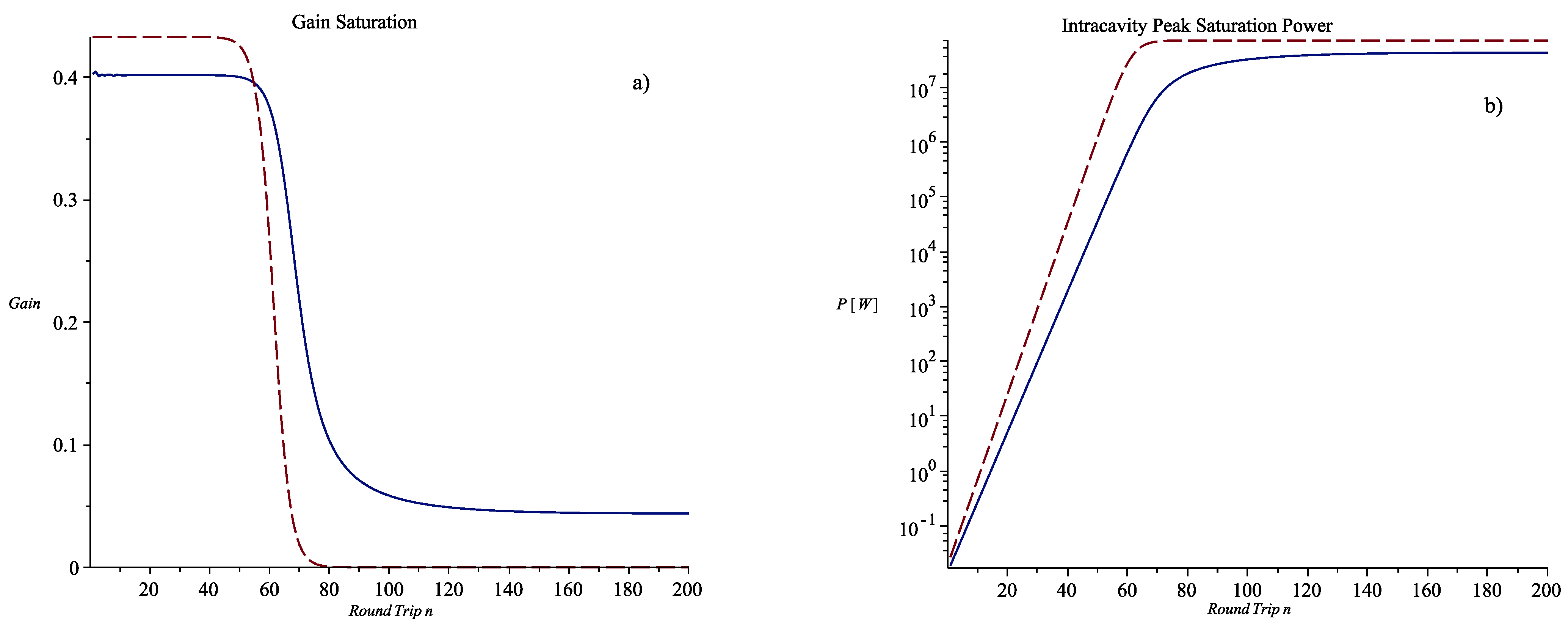
The behaviour of Equation (7) is reported in Figure 3a) for the gain expressions, GI and GII, as a function of the round trip number n, and in Figure 3b) for the ongoing power radiation, In and I(n), again with respect to the round trip. The main result, as can be deduced from Figure 3, is that saturation is reached after about n = 100 round trips considering both methods reported in Equation (7). Considering the resonator length, as indicated in Table 1, we can deduce that saturation is gained in about TSAT ~200 ns, which is quite a short time with respect to the conventional macro-bunch duration of electron pulses generated by RF accelerators in the S-band (~3 GHz), which of the order of several microseconds. This will be relevant for the analysis of the velocity modulation induced on the remaining part of the macro-bunch itself.
The peak intra-cavity peak power, as deduced by Figure 3b), is about PSAT ~4.2 × 10⁷ W; considering an average transverse radiation dimensions, obtained from the data reported in Table 1, of about ΣL = 1 cm2, the electric field associated to the intracavity radiation at saturation is:
Before analysing the dynamical process, it is worth briefly addressing the question of the longitudinal modes in the Cerenkov FEL resonator. The wavenumber mode separation, as evident from Equation (6), is (Δω/c) = π/L. The relative gain bandwidth is [11,15]:
The number of modes contained in the gain bandwidth is therefore: ΔωG/Δω = γ2. It is well known [11] that any FEL based on the RF accelerator locks all the longitudinal modes in a natural way. The result of such mode-locking is that a single short pulse of radiation travels back and forth inside the tuned resonator with a group velocity that is slightly smaller than that of the electron beam, causing a kind of anti-lethargic effect [23], unlike what happens for undulator FELs.
4. Electron Beam Modulation and Undulator Emission
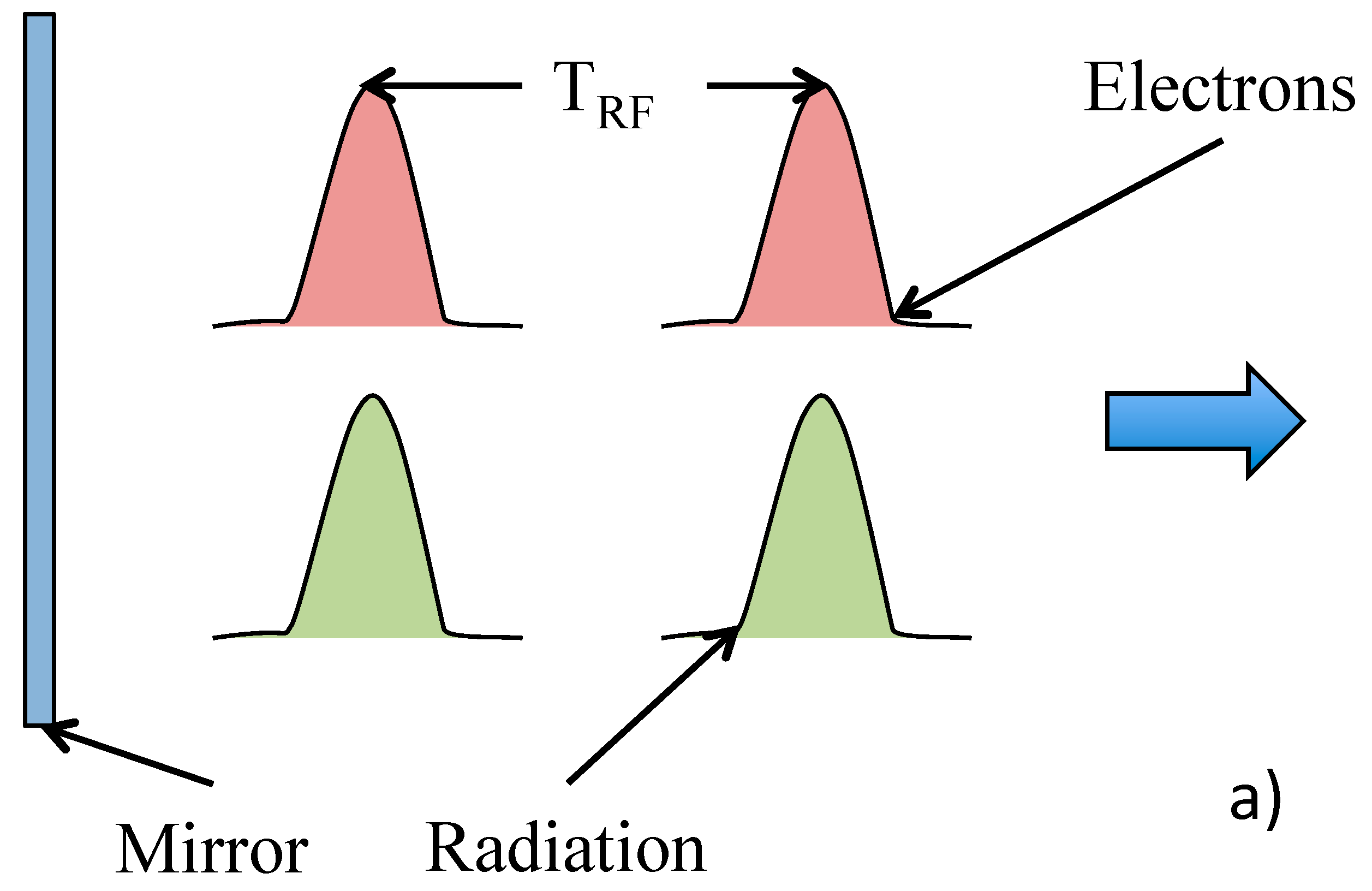
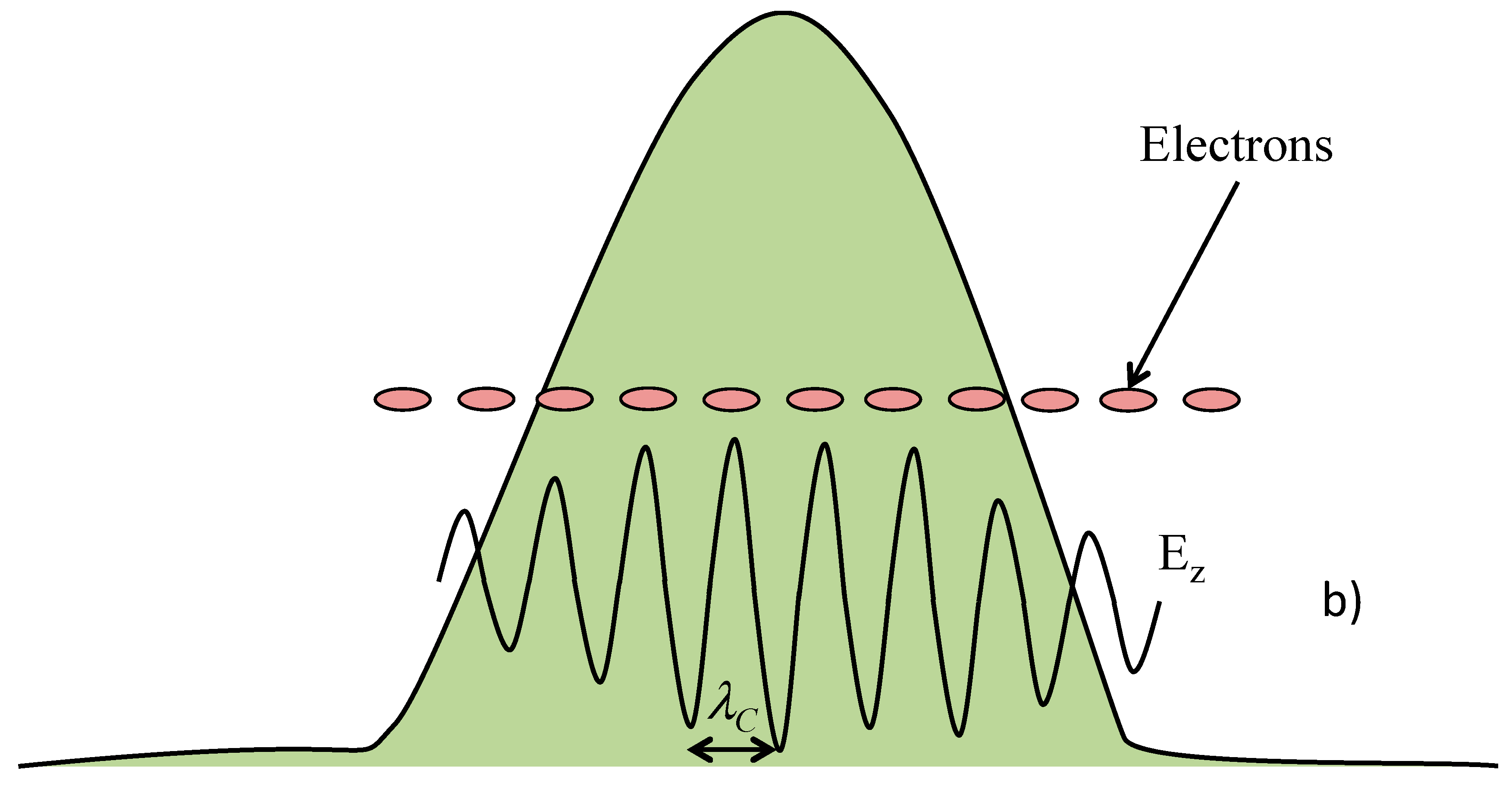
At the end of the previous section, we saw how an intense electromagnetic pulse, that can be generated inside an optical resonator in about 200 nanoseconds, needs to be saturated. For electron macro-bunches, as long as few microseconds we will have thousands of micro-bunches available interacting with the electromagnetic field. If we analyse each of these electron micro-bunches, we recognise that, at the resonator entrance, each of them superimposes with a correspondent radiation micro-pulse as illustrated in Figure 4a). In such a situation, the electrons of the bunch, generally equally spaced in phase, will experience the oscillating longitudinal electric field Ez (Equation (6)) with a spatial periodicity of λC, as showed in Figure 4b). The situation represented in Figure 4 is quite similar to that of an electron beam accelerated by a series of RF cavities such as those of a standing-wave Linac [11,24]. The number of cavities can be estimated by calculating the number of the electric field oscillations “contained” within the electron micro-bunch length (δz~τeβec) divided by the wavelength λC: Nc~(δz/λC). The most widely used accelerators for FELs operate in the so-called S-band (νRF~3 GHz) and generate micro-bunches of a typical duration of τe~15 ps, which corresponds to a bunch length of about δz~5 mm. Considering a radiation wavelength of λC~250 μm, as for the example discussed in the previous sessions, we obtain Nc~20.
It is possible, therefore, to imagine any optical cycle acting on the electrons in a way similar to that of the accelerating cavities of a Linac. We know, in fact, that electrons undergo to an energy variation that is connected to the particle-radiation relative phase. Such an energy variation will be positive for electrons close to the so-called accelerating phase and negative for those with an opposite phase. The result is a bunching of the electrons into Nc “slices”.
To properly evaluate the energy variation of a single electron, let us consider that the energy exchange occurs along the time needed for the electron, to cross the resonator length L. The particle, during this time T = L/(cβe), experiences a quasi-static electric field due to the fact that, even with small differences, its speed is almost synchronous with the electromagnetic pulse that travels with its group velocity (see Equation (5)), and therefore, βg~βe. The energy variation, for each electron, is consequently:
where the longitudinal electric field has been derived from Equation (6) and the constant term E0z contains the transverse coupling between the electron and the evanescent field in the x direction. Before getting an explicit form for Equation (8), it is worth underlining that the phase φ usually refers to the RF field, at an angular frequency ωRF, that accelerates the electron beam in the accelerator (Linac, for instance). In the present case, the phase φ should be referred to as the Cerenkov radiation field in the optical resonator, and therefore, ought to be “normalised” by means of the frequency ratio : . After some algebra, we obtain:
The result of what has been discussed is that the energy modulation expressed by Equation (9) can be exploited to generate powerful radiation inside a magnetic undulator utilised as a radiator. The discussion after Equation (2) in Section 2 leads to a set of parameters, summarised in Table 3, for an undulator synchronous with the fundamental Cerenkov emission.
The emission of radiation from a radiator by means of an ensemble of charged particles distributed in the phase space has been faced in the recent past [25,26]. To summarise some concepts, we can say that the electron beam, after the interaction, carries a modulation of the current that can be expressed as a Fourier expansion in terms of the harmonics l of the RF. Moreover, the electromagnetic field can be expanded in terms of the transverse modes, expressed by the aggregate index λ, of the waveguide that is needed to confine the radiation in the far infrared spectral range, and expressing the expansion coefficients as . Finally, the power , emitted due to the energy exchange between the electron beam and the radiation field in the magnetic field of the undulator, can be evaluated by means of the flux of the Poynting vector. Equation (10) summarises all the above in an extensive demonstration which can be found in [25] and the references therein:
where e is the electron charge, Z0 is the vacuum impedance, is the radiation transverse mode size, Ne is the number of electrons contained in the bunch, βz,j is the longitudinal velocity of the j-th electron, βg is the radiation group velocity and is the transverse mode momentum.
A brief analysis of Equation (10) tells us that the expansion coefficient plays a significant function in the determination of the radiation formation. It is, in fact, the role of each electron in the bunch is relevant because it carries a specific energy γj and a specific phase ψj. In particular, the electron phase ψj, together with the interaction phase enter in a more general phase term in that, when summing up all of the contributions of the Ne electrons of the bunch, may generate constructive or destructive interactions. The maximum radiated power in the undulator is obtained when all the electrons contribute to the radiation formation with the same phase term (only depending on the harmonic number l), therefore, with an adequate distribution of the electrons in the phase-space.
What has been discussed, so far, about Equation (10), refers to the longitudinal properties of the particle–wave interaction, which concur with the undulator parameter K and period λw and the electron longitudinal velocities βz,j. The transverse characteristics of the radiation emission are summarised by the mode aggregate index λ. It is evident, however, that the transverse space can play a role when the electron beam emittance values could be relevant for the radiation wavelength to be generated. A deeper and exhaustive analysis can be found in [27].
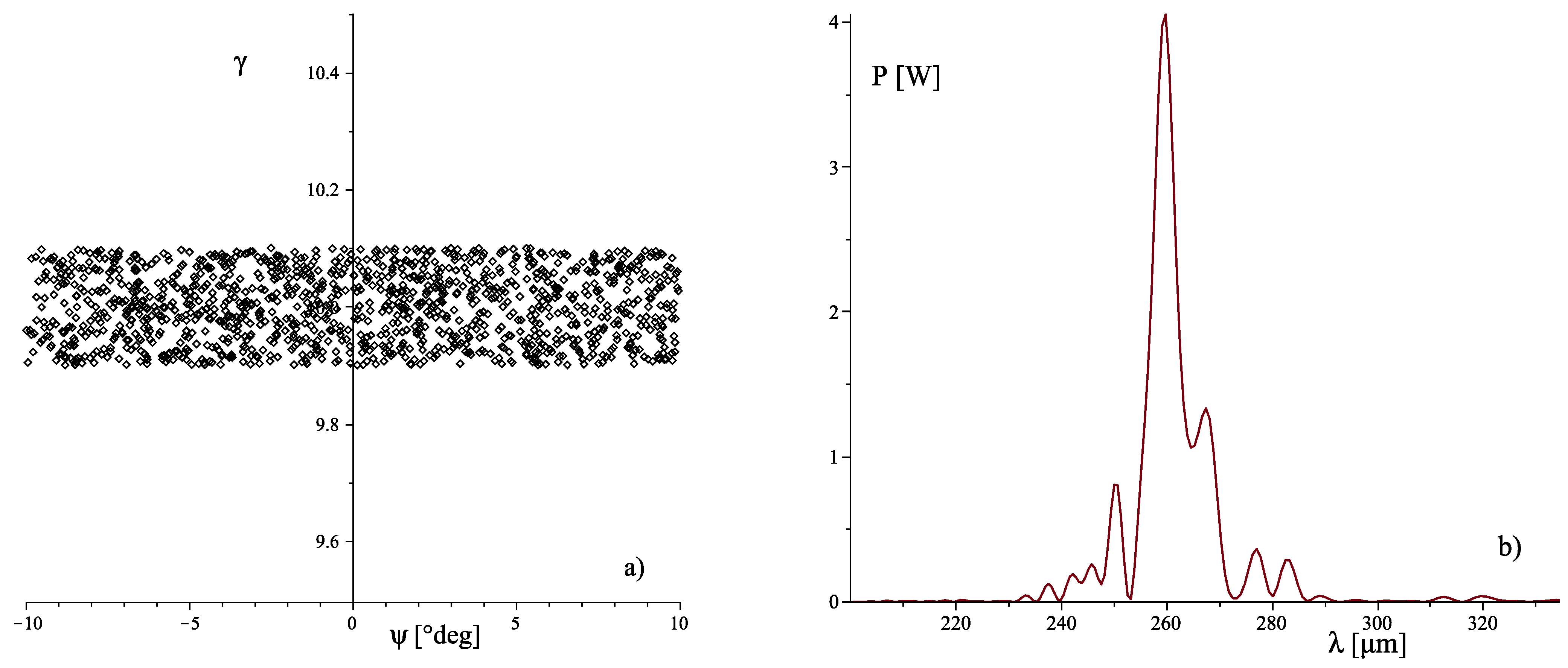
With such a mathematical background, an appropriate computational code was set up for the evaluation of the coherent generation of radiation in the undulator–radiator. The code is capable of evaluating the impact of an electron bunch, with a specific distribution in the phase-space, for the radiation generation, calculating the contribution of any electron, integrated along the interaction length. The code, at the moment, does not take into account saturation effects. The effect of the energy modulation introduced by the electron–field interaction inside the Cerenkov FEL optical resonator can be assessed by comparing the emission from an electron distribution and the same distribution to which an energy modulation is added , where the contribution is calculated from Equation (9) for each electron. To this aim, an ad hoc electron distribution was generated in the phase-space having a uniform partitioning in energy with a total Δγ = 0.2 around γ = 10 (see Table 3) corresponding to a r.m.s. The phase partitioning is again uniform, with an added Poissonian component, with a total Δψ = 20° corresponding to the actual micro-bunch duration expressed as phase interval for Linac [11]. In Figure 5, we report the aforementioned electron distribution (Figure 5a) together with the corresponding power spectrum (Figure 5b) calculated with Equation (10). The total power, integrated over the whole bandwidth, results in PTOT~55 W.
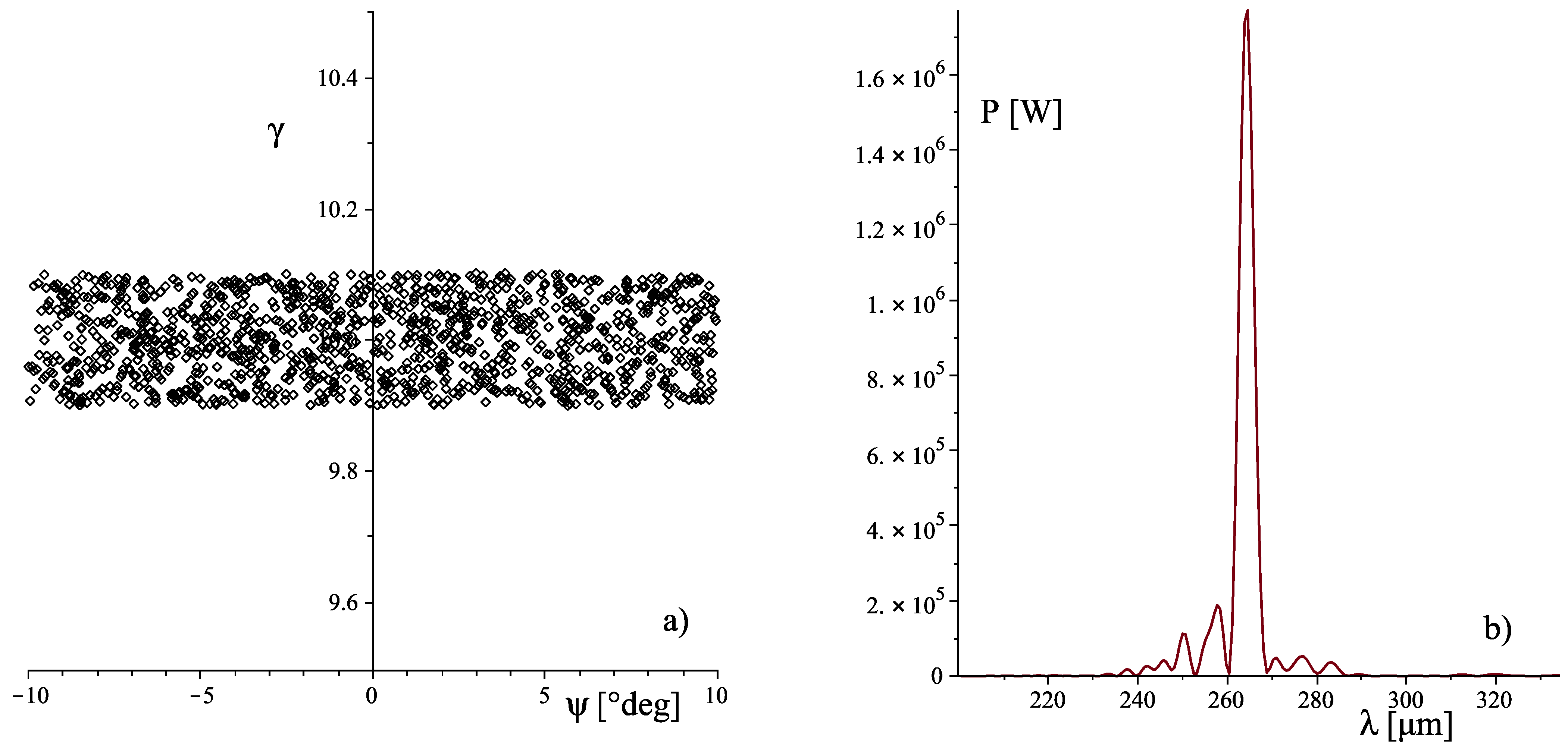
As anticipated, a similar calculation can be performed for the electron distribution of Figure 5a), to which the energy modulation Δγj of Equation (9) is added for each electron of the distribution with its actual phase ψj and energy (through the velocity βe,j). The amplitude of the electric field is the one evaluated at the end of Section 3 from the saturated intracavity radiation power E0z~1.8 × 10⁷ [V/m]. In Figure 6, we report the energy modulated electron distribution (Figure 6a) together with the corresponding power spectrum (Figure 6b), again calculated by means of Equation (10). As can be clearly seen, the emission is strongly increased by orders of magnitude due to the modulation introduced which, moreover, is not clearly distinguishable when looking at Figure 5a and Figure 6a. It is further worth underlining how the total bandwidth is slightly reduced with respect to the unmodulated case. The total power, integrated over the whole bandwidth, now results as PTOT~1.28 × 10⁷ W.
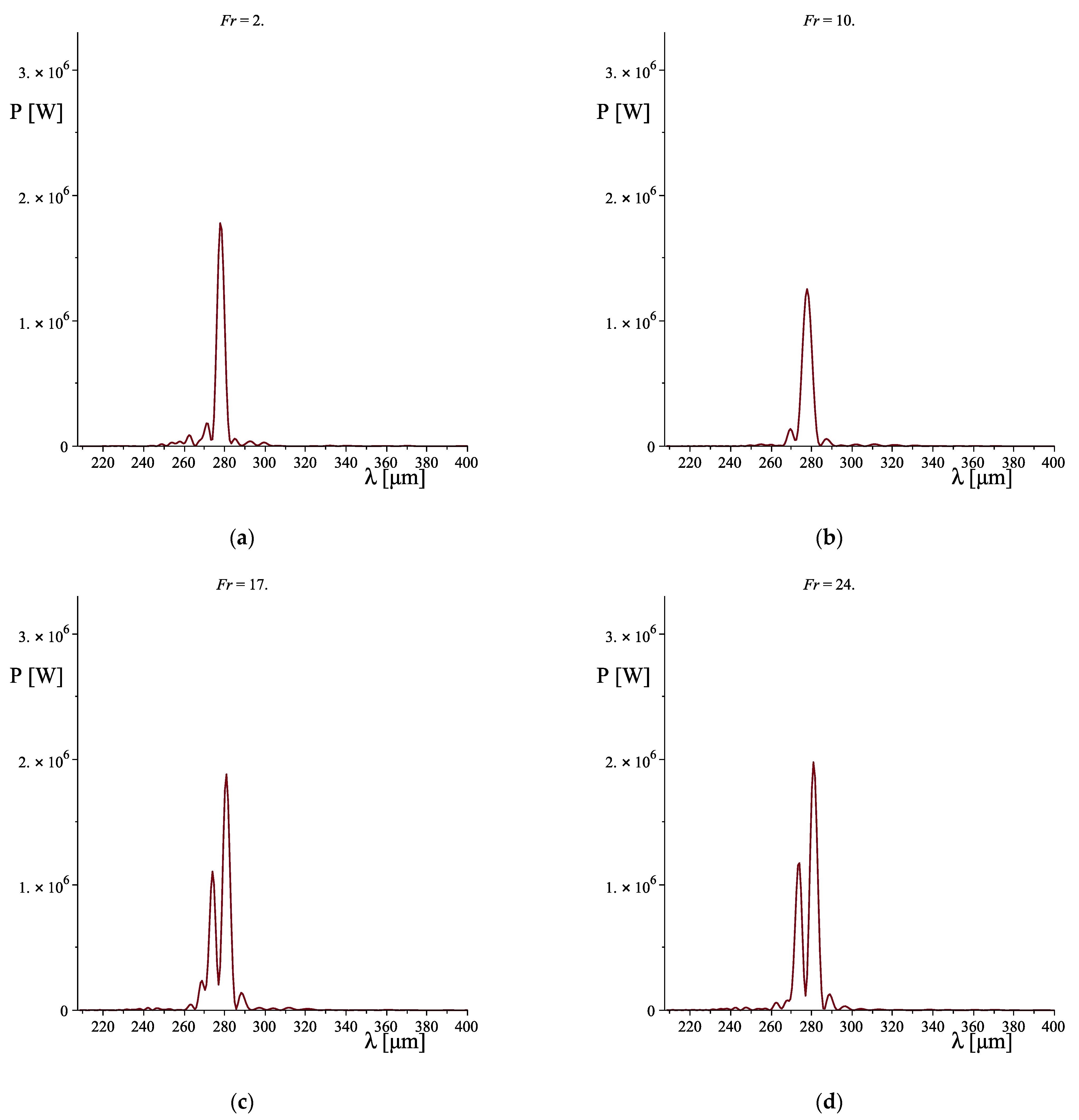
We may now ask whether there is any optimisation procedure to further increase the power radiated by the undulator. The most relevant tool is the distance between the Cerenkov electromagnetic resonator and the entrance of the magnetic undulator. This is because the energy modulation acquired by the electrons in the cavity transforms into a velocity modulation, and consequently bunches before entering the undulator interaction region. This “drift space” allows a ballistic process that correlates the velocity variation of each electron, with its position, and therefore phase, in the bunch. In Equation (11), we report the phase term that should be inserted in the set of Equation (10) that takes into account the phase variation, after the velocity modulation expressed by (vz)j and for a specific drift space LDrift. The index “j” indicates the specific electron and vref is the velocity of the “reference electron”:
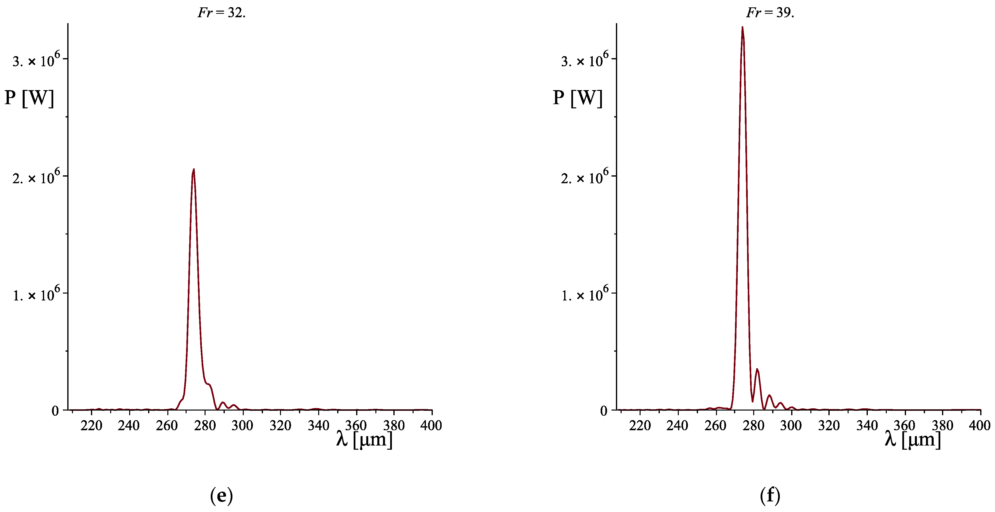
Considering a series of values for LDrift ranging from 0 to 3.5 metres, the power spectrum was calculated and reported in Figure 7. As can be appreciated, the peak power, starting from a specific value, tends to reduce, while increasing LDrift, and the spectrum itself tends to broaden with a couple of peaks appearing. A further increase in the modulator radiator distance produces a spectral band reduction and a peak power increase up to the final value.
5. Conclusions
The example reported to date indicates how a hybrid scheme for free electron devices can be effective for the power enhancement of the electromagnetic radiation generated. This two-elements scheme, based on an oscillator, in which intracavity radiation acts as an energy modulator, and a magnetic undulator as a radiator, is a versatile arrangement because the oscillator section can be chosen among a series of different devices. As anticipated, together with the Cerenkov device, other sources can be taken into account; among which the Smith–Purcell is an interesting choice because it offers characteristics that lay between that of a Cerenkov FEL (being a slow-wave device) and an undulator FEL (wavelength scales inversely with the electron energy, as can be seen in Equation (12)). The synchronic condition, in fact, results to be [10,28]:
where Λ represents the grating period, nso indicates the grating spectral order and θ is the angle between the electron beam direction (parallel to the grating surface) and the observer. A new parameter, in the Smith–Purcell-based FEL, is evident from Equation (12) and is the angle θ that offers a wide and continuous range of spectral tunability [28] that can be exploited, keeping fixed other parameters like the electron energy and the grating geometry. This characteristic increases the flexibility of the hybrid scheme FEL because it easily allows to obtaining the condition λU = λSP/n, where n = 1, 2, …, because the cos θ term can be used to obtain the maximum wavelength extension:
The harmonic number n is, therefore, a pivotal parameter for extending the spectral emission of such a coherent source [5,6,7], that with a proper combination of all the parameters involved, for both the oscillator and the radiator, prove to be a promising and versatile device, with the additional feature of compactness.
Funding
This research received no external funding.
Institutional Review Board Statement
Not applicable.
Informed Consent Statement
Not applicable.
Data Availability Statement
Not applicable.
Conflicts of Interest
The authors declare no conflict of interest.
References
- Pantell, R.H.; Soncini, G.; Puthoff, H.E. Stimulated photon-electron scattering. IEEE J. Quantum Electron. 1968, QE-4, 905–907. [Google Scholar] [CrossRef]
- Deacon, D.A.G.; Elias, L.R.; Madey, J.M.J.; Ramian, G.J.; Schwettman, H.A.; Smith, T.I. First Operation of a Free-Electron Laser. Phys. Rev. Lett. 1977, 38, 892–894. [Google Scholar] [CrossRef]
- van Amersfoort, P.W.; Bakker, R.J.; Bekkers, J.B.; Best, R.W.B.; van Buuren, R.; Delmee, P.F.M.; Faatz, B.; van der Geer, C.A.J.; Jaroszynski, D.A.; Manintveld, P.; et al. First lasing with FELIX. Nucl. Instr. Meth. 1992, A318, 42–46. [Google Scholar] [CrossRef]
- Milton, S.V.; Gluskin, E.; Arnold, N.D.; Benson, C.; Berg, W.; Biedron, S.G.; Borland, M.; Chae, Y.C.; Dejus, R.J.; Den Hartog, P.K.; et al. Exponential gain and saturation of a self-amplified spontaneous emission free-electron laser. Science 2001, 292, 2037–2040. [Google Scholar] [CrossRef] [PubMed] [Green Version]
- Bonifacio, R.; De Salvo Souza, L.; Pierini, P.; Scharlemann, E.T. Generation of XUV Light by Resonant Frequency Tripling in a two Wiggler FEL Amplifier. Nucl. Instr. Meth. 1990, A296, 787–790. [Google Scholar] [CrossRef]
- Dattoli, G.; Doria, A.; Giannessi, L.; Ottaviani, P.L. Bunching and exotic undulator configurations in SASE FELs. Nucl. Instr. Meth. 2003, A507, 388–391. [Google Scholar] [CrossRef]
- Ciocci, F.; Dattoli, G.; De Angelis, A.; Faatz, B.; Garosi, F.; Giannessi, L.; Ottaviani, P.L.; Torre, A. Design Considerations on a High-Power VUV FEL. IEEE J. Quantum Electron. 1995, QE-31, 1242–1252. [Google Scholar] [CrossRef]
- Asgekar, V.; Dattoli, G. Hybrid free electron laser devices. J. Appl. Phys. 2007, 101, 063111-1–063111-4. [Google Scholar] [CrossRef]
- Ciocci, F.; Dattoli, G.; Doria, A.; Schettini, G.; Torre, A.; Walsh, J.E. Spontaneous Emission in Cerenkov FEL Devices: A Preliminary Theoretical Analysis. Il Nuovo Cimento 1988, 10D, 1–20. [Google Scholar] [CrossRef]
- Urata, J.; Goldstein, M.; Kimmitt, M.F.; Naumov, A.; Platt, C.; Walsh, J.E. Superradiant Smith-Purcell Emission. Phys. Rev. Lett. 1998, 80, 516–519. [Google Scholar] [CrossRef]
- Dattoli, G.; Doria, A.; Sabia, E.; Artioli, M. Charged Beam Dynamics, Particle Accelerators and Free Electron Lasers, 1st ed.; IOP Publishing Ltd.: Bristol, UK, 2017. [Google Scholar]
- Roberts, S.; Coon, D.D. Far-Infrared Properties of Quartz and Sapphire. J. Opt. Soc. Am. 1962, 52, 1023–1029. [Google Scholar] [CrossRef]
- Collin, R.E. Foundations of Microwave Engineering; McGraw-Hill: Singapore, 1966. [Google Scholar]
- Walsh, J.E. Stimulated Cerenkov Radiation. Adv. Electron. Electron Phys. 1982, 58, 271–310. [Google Scholar]
- Dattoli, G.; Doria, A.; Gallerano, G.P.; Renieri, A.; Schettini, G.; Torre, A. A Single-Particle Calculation of the FEL-Cerenkov Gain. Il Nuovo Cim. 1988, 101B, 79–84. [Google Scholar] [CrossRef]
- Ciocci, F.; Dattoli, G.; Doria, A.; Gallerano, G.P.; Schettini, G.; Torre, A. Spontaneous Emission in a Double Dielectric Slab for Cerenkov Free-Electron-Laser Operation. Phys. Rev. A 1987, 36, 207–210. [Google Scholar] [CrossRef] [PubMed]
- Dattoli, G. Logistic function and evolution of free-electron-laser oscillators. J. Appl. Phys. 1998, 84, 2393–2398. [Google Scholar] [CrossRef]
- Andrews, H.L.; Brau, C.A. Three-dimensional theory of the Cerenkov free-electron laser. J. Appl. Phys. 2007, 101, 104904-1–104904-6. [Google Scholar] [CrossRef] [Green Version]
- Rigrod, W.W. Gain Saturation and Output Power of Optical Masers. J. Appl. Phys. 1963, 34, 2602–2603. [Google Scholar] [CrossRef]
- Herman, A.H. Theory of mode locking with a fast saturable absorber. J. Appl. Phys. 1975, 46, 3049–3058. [Google Scholar]
- Dattoli, G.; Cabrini, S.; Giannessi, L. Simple model of gain saturation in free-electron lasers. Phys. Rev. A 1991, 44, 8433–8434. [Google Scholar] [CrossRef]
- Dattoli, G.; Giannessi, L.; Ottaviani, P.L.; Carpanese, M. A simple model of gain saturation in high gain single pass free electron lasers. Nucl. Instr. Meth. 1997, A393, 133–136. [Google Scholar] [CrossRef]
- Dattoli, G.; Doria, A.; Gallerano, G.P.; Schettini, G.; Torre, A.; Walsh, J.E. Pulse Propagation Theory for the Cerenkov Free-Electron Laser. Il Nuovo Cim. 1989, 103B, 281–289. [Google Scholar] [CrossRef]
- Wangler, T.P. Introduction to Linear Accelerator Theory; LAUR-93-805; Los Alamos National Laboratory: Washington, DC, USA, 1993.
- Doria, A.; Gallerano, G.P.; Giovenale, E.; Letardi, S.; Messina, G.; Ronsivalle, C. Enhancement of Coherent Emission by Energy-Phase Correlation in a Bunched Electron Beam. Phys. Rev. Lett. 1998, 80, 2841–2844, and references therein. [Google Scholar] [CrossRef]
- Doria, A.; Gallerano, G.P.; Giovenale, E. Novel Schemes for Compact FELs in the THz Region. Condens. Matter 2019, 4, 90. [Google Scholar] [CrossRef] [Green Version]
- Bahrdt, J. Shaping Photon Beams with Undulators and Wigglers. In Synchrotron Light Sources Free Electron Lasers; Springer: Berlin/Heidelberg, Germany, 2016; pp. 751–819. [Google Scholar]
- Doucas, G.; Kimmitt, M.F.; Doria, A.; Gallerano, G.P.; Giovenale, E.; Messina, G.; Andrews, H.L.; Brownell, J.H. Determination of longitudinal bunch shape by means of coherent Smith-Purcell radiation. Phys. Rev. Accel. Beams 2002, 5, 072802-1–072802-8. [Google Scholar] [CrossRef] [Green Version]
Figure 1.
Schematic drawing of the hybrid FEL under study. The accelerated electron beam generates radiation interacting with the Cerenkov resonator. The electric beam associated with the stored radiation modulates the electrons’ velocities in order to obtain the most efficient emission in the magnetic undulator radiator.

Figure 2.
Spontaneous emission spectra as a function of the beam centroid distance from the dielectric surface: (a) single slab waveguide geometry; and (b) double slab waveguide geometry.
Figure 2.
Spontaneous emission spectra as a function of the beam centroid distance from the dielectric surface: (a) single slab waveguide geometry; and (b) double slab waveguide geometry.

Figure 3.
Saturation behaviour: (a) gain as a function of the round-trip number; and (b) intracavity power as a function of the round-trip number.
Figure 3.
Saturation behaviour: (a) gain as a function of the round-trip number; and (b) intracavity power as a function of the round-trip number.

Figure 4.
Electron bunch and radiation pulse interaction: (a) phase locking; and (b) electrons and radiation electric field interaction.
Figure 4.
Electron bunch and radiation pulse interaction: (a) phase locking; and (b) electrons and radiation electric field interaction.


Figure 5.
Emission by undulator–radiator: not the modulated case: (a) phase-space; and (b) power spectrum.
Figure 5.
Emission by undulator–radiator: not the modulated case: (a) phase-space; and (b) power spectrum.

Figure 6.
Emission by undulator–radiator: modulated case: (a) phase-space; and (b) power spectrum.

Figure 7.
Power spectrum for different drift-space values: (a) LDrift = 0.18 m; (b) LDrift = 0.90 m; (c) LDrift = 1.52 m; (d) LDrift = 2.15 m; (e) LDrift = 2.87 m; and (f) LDrift = 3.50 m.
Figure 7.
Power spectrum for different drift-space values: (a) LDrift = 0.18 m; (b) LDrift = 0.90 m; (c) LDrift = 1.52 m; (d) LDrift = 2.15 m; (e) LDrift = 2.87 m; and (f) LDrift = 3.50 m.


Table 1.
Cerenkov FEL Parameters @ λ = 250 μm.
| Cerenkov FEL Parameters @ λ = 250 μm | |||||
|---|---|---|---|---|---|
| Electron Energy | Dielectric Thickness | Dielectric Constant | Resonator Length | Resonator Width | Double Slab Height |
| γ = 10.0 | d = 50 μm | ε = 5.0 | L = 35.0 cm | W = 1.0 cm | D = 2 cm |
Table 2.
Cerenkov FEL Gain Parameters @ λ = 250 μm.
| Cerenkov FEL Gain Parameters @ λ = 250 μm | |||||
|---|---|---|---|---|---|
| Electron Bunch Current | Angular Distribution | Transverse Distribution | Peak Gain Coefficient | Total Resonator Losses | Intracavity Equilibrium Power |
| I0 = 20.0 | σ′ = 5 × 10⁻⁴ (r.m.s.) | σx = 1 mm (r.m.s.) | g0MAX = 0.4 | Γ = 0.042 | Ie,i = 7.22 × 10⁷ W |
Table 3.
Undulator–Radiator FEL Parameters @ λU = 250 μm.
| Undulator–Radiator FEL Parameters @ λU = 250 μm | |||||
|---|---|---|---|---|---|
| Electron Energy | Undulator Period | Undulator Parameter | Number of Periods | Waveguide Width | Waveguide Height |
| γ = 10.0 | λw = 2.5 cm | =1.0 | NU = 50 | W = 0.5 cm | H = 0.5 cm |
Publisher’s Note: MDPI stays neutral with regard to jurisdictional claims in published maps and institutional affiliations. |
© 2021 by the author. Licensee MDPI, Basel, Switzerland. This article is an open access article distributed under the terms and conditions of the Creative Commons Attribution (CC BY) license (https://creativecommons.org/licenses/by/4.0/).
Share and Cite
MDPI and ACS Style
Doria, A. Hybrid (Oscillator-Amplifier) Free Electron Laser and New Proposals. Appl. Sci. 2021, 11, 5948. https://doi.org/10.3390/app11135948
AMA Style
Doria A. Hybrid (Oscillator-Amplifier) Free Electron Laser and New Proposals. Applied Sciences. 2021; 11(13):5948. https://doi.org/10.3390/app11135948
Chicago/Turabian StyleDoria, Andrea. 2021. "Hybrid (Oscillator-Amplifier) Free Electron Laser and New Proposals" Applied Sciences 11, no. 13: 5948. https://doi.org/10.3390/app11135948
Note that from the first issue of 2016, this journal uses article numbers instead of page numbers. See further details here.