
Multi-Manned Assembly Line Balancing: Workforce Synchronization for Big Data Sets through Simulated Annealing


1
Department of Industrial Engineering, University of Trento, Via Sommarive 9, 38123 Trento, Italy
2
Department of Industrial Engineering, University of Bologna, Viale del Risorgimento 2, 40136 Bologna, Italy
*
Author to whom correspondence should be addressed.
Appl. Sci. 2021, 11(6), 2523; https://doi.org/10.3390/app11062523
Submission received: 29 January 2021
/
Revised: 18 February 2021
/
Accepted: 8 March 2021
/
Published: 11 March 2021
Abstract
:The assembly of large and complex products such as cars, trucks, and white goods typically involves a huge amount of production resources such as workers, pieces of equipment, and layout areas. In this context, multi-manned workstations commonly characterize these assembly lines. The simultaneous operators’ activity in the same assembly station suggests considering compatibility/incompatibility between the different mounting positions, equipment sharing, and worker cooperation. The management of all these aspects significantly increases the balancing problem complexity due to the determination of the start/end times of each task. This paper proposes a new mixed-integer programming model to simultaneously optimize the line efficiency, the line length, and the workload smoothness. A customized procedure based on a simulated annealing algorithm is developed to effectively solve this problem. The aforementioned procedure is applied to the balancing of the real assembly line of European sports car manufacturers distinguished by 665 tasks and numerous synchronization constraints. The experimental results present remarkable performances obtained by the proposed procedure both in terms of solution quality and computation time. The proposed approach is the practical reference for efficient multi-manned assembly line design, task assignment, equipment allocation, and mounting position management in the considered industrial fields.
1. Introduction
Considering the tremendous competitiveness distinguishing today’s production environment, the optimal design of assembly systems is a necessary requirement to consolidate and enhance the competitive advantage of most manufacturing companies [1,2]. In particular, the assembly of large products such as cars, buses, tracks, automatic machines, and white goods requires the combination of a great number of components and parts, and it represents a relevant production process in terms of space and resource utilization [3]. In addition, assembly activities still involve a large workforce since most of the tasks require manual labor due to handling skills, acquired experience, and specific competencies difficult to be taught to autonomous robots [4,5]. In this context, assembly system performance optimization plays a crucial role in terms of productivity growth and cost reduction; indeed, even small improvements can lead to significant monetary savings. Accordingly, the workforce, the layout, and the equipment should be properly designed and managed through efficient assembly line balancing and synchronization. Although the pressure to improve these assembly system performances is relevant in several industries, such as automotive, the literature contributions about this field of research are not abundant [6].
Traditionally, the aim of the assembly line balancing problem (ALBP) is to assign a set of tasks to the workstations composing the assembly line optimizing one or more objectives without violating any restriction imposed for the line [7]. These restrictions typically include cycle time fulfillment and other technological or organizational constraints represented by the task precedence diagram [8]. These basic limitations characterize the simple assembly line balancing problem (SALBP) [9], which considers no task assignment limitations aside from those related to precedence constraints, a single worker per workstation, and all stations equally equipped with resources. These hypotheses rarely occur in real industrial contexts; thus, several studies have recently evolved toward formulating and solving generalized assembly line balancing problems (GALBPs) with different additional characteristics [10,11]. Sivasankaran and Shahabudeen [12] investigated the possibility of classifying GALBPs depending on multiple factors, including the number of workers per station. Considering this criterion, ALBPs can be categorized into three groups—simple, two-sided, and multi-manned lines. An example of such assembly line configurations is shown in Figure 1. In a two-sided assembly line arrangement, two workers per station execute different tasks on both sides of the line. In most cases, some tasks have necessarily to be processed on a specific side of the line while others may be executed on either side [13]. On the contrary, multi-manned assembly lines are characterized by several workers in each station who simultaneously perform different tasks on the same product [14].
The leading goal of multi-manned assembly lines is to minimize the total workstation number while the overall efficiency of the line, in terms of worker number and their saturation, remains optimal or near-optimal. The balancing of assembly lines with multi-manned workstations involves two decisions, namely, (1) how many workers should be allocated to each station without exceeding the maximum feasible number of workers performing tasks together on the same product and (2) which subset of tasks should be assigned to each worker and in which chronological order.
The main difference between the assignment of tasks in simple and two-sided lines compared to multi-manned ones is the relevance of the temporal sequence in which the tasks are performed by the workers. For traditional lines, the sequence of the tasks within a workstation is not relevant as long as it fulfills the precedence constraints. On the contrary, this is a crucial factor for assembly lines with more than one worker per station to obtain an efficient task assignment. Indeed, some tasks assigned to a worker could be delayed if they need to wait for a predecessor task to be completed. Accordingly, the station assembly time cannot be computed by simply summing up the assigned task times, but it requires the solution of a detailed scheduling problem within each station [15]. Addressing these peculiarities of multi-manned assembly lines considerably increases the problem complexity and the simple balancing of workloads among workers is no longer enough. Conversely, proper synchronization of the task assignment to workers is necessary to attain feasible solutions.
In addition to the precedence diagram, several other restrictions can force or forbid particular task combinations or certain task assignments to a specific worker in a certain instant [16,17]. For instance, large products require different mounting positions to be handled by workers. As suggested by Lapierre and Ruiz [18], each position enables certain tasks to be assigned and disables some others. Moreover, some tasks could require specific tools or machines to be performed [19]. Hence, a further decision about the equipment types to be allocated to the workstations has to be taken. An efficient task-to-station assignment should consider a maximum number of pieces of equipment installed overall. Workers belonging to the same station could share these pieces of equipment, using them in different moments during the cycle time. Finally, some tasks may require cooperation between two or more workers to be carried out, e.g., windshield installation for cars.
This paper tackles the problem of synchronizing assembly lines of large and complex products, e.g., cars, trucks, automatic machines, and white goods. The aim of this research is the development of a methodology suitable for industrial applications able to simultaneously handle all the typical features of these assembly systems. These features are multi-manned workstations, compatibility/incompatibility between mounting positions, equipment sharing, cooperation between workers, and the management of a great number of tasks, i.e., some hundreds.
The adopted research methods deal with a detailed analysis of the targeted problem, defining the most relevant features that distinguished real multi-manned assembly lines within an industrial environment. Then, all these relevant features are quantitatively modeled to define a feasible optimization problem since a procedure able to solve this complex multi-manned assembly line synchronization problem (MALSP) is missing in the literature and it is strongly encouraged by industries. First, a mixed-integer programming (MIP) model for this MALSP is presented. Secondly, because this problem is well known as non-polynomial (NP)-hard, a customized meta-heuristic procedure based on a simulated annealing (SA) algorithm is implemented to efficiently solve it. Moreover, the paper presents the assembly dataset of a European luxury sports car manufacturer. This instance involves 665 tasks, and it can probably be considered one of the largest available in the literature, as far as the authors’ knowledge. The proposed MIP model is adopted to solve the case study MALSP leveraging the presented SA algorithm. This approach is tested and validated through its successful application to the targeted automotive assembly line. The obtained results demonstrate the procedure efficiency, and the quality of the proposed solutions suggest that it can be a practical reference for companies that tackle the workstation design, the worker and equipment allocation, and the task assignment within multi-manned assembly systems.
The remainder of this paper is organized as follows. Section 2 investigates the most relevant contributions to multi-manned assembly line problems by considering the latest trends. Section 3 analyzes the most relevant features of the complex MALSP. In Section 4, a MIP model for the MALSP is proposed including equipment sharing limitations, compatible mounting position restrictions, and worker cooperation. Section 5 examines a customized version of a SA procedure as an effective solution methodology for the synchronization of these assembly lines. In Section 6 the dataset of a European manufacturer of luxury sports cars is presented, and the parameters of the proposed SA procedure are calibrated to apply them to the considered case study. The results obtained through the procedure validation are analyzed in Section 7, proposing the optimal synchronization solution of the case study along with the detailed scheduling of the tasks assigned to each worker over the cycle time. Finally, Section 8 concludes the paper and suggests future research opportunities.
2. Literature Review
Multi-manned assembly lines are spread widely in production systems of different industries, but the literature contributions about this topic are not abundant. Dimitriadis [14] is probably the first researcher who analyzed assembly lines with multi-manned workstations. He proposed a two-level heuristic approach based on the Hoffmann algorithm [20] to solve the multi-manned assembly line balancing problem (MALBP), considering a dataset of 64 tasks from a Greek automotive company. Afterward, Cevikcan et al. [21] devised a mathematical programming model and a scheduling-based heuristic algorithm to design multi-manned workstations for the mixed model assembly line.
Pearce et al. [22] considered a special case of MALBP with parallel workers and additional assignment restrictions. They assumed that the workpiece is divided into mounting positions each of which can be used by only a single worker in each workstation. In their study, tasks that require at least one joint mounting position have to be assigned to the same worker. To solve the problem distinguished by similar features, Becker and Scholl [23] developed an exact solution procedure based on a branch and bound algorithm for small- and medium-size problems and a heuristic procedure for large-scale problems.
Roshani et al. [24] and Fattahi et al. [25] validated, respectively, their SA and ant colony algorithms, exploiting the problems collected by Talbot and Patterson [26]. This dataset presents small- and medium-size problems since only one precedence diagram features more than 100 tasks. Concerning the objective functions traditionally adopted as MALBP goals, Fattahi et al. [25] considered the minimization of the total worker number of the line as the primary objective and the multi-manned workstation number as the secondary one, whereas Roshani et al. [24] used the minimum deviation method to merge into a single metric three objective functions, namely, line efficiency, line length, and smoothness index. Similarly, a novel MALBP formulation was proposed by Yilmaz and Yilmaz [27] to minimize the number of workers and workstations for a given cycle time and reduce the difference between the worker’s load in each multi-manned workstation.
Several literature contributions focus on the development of efficient and effective MALBP solving procedures, considering that the computation complexity of these problems exponentially increases with the dataset size, i.e., task number and constraint considered. Kellegöz and Toklu [28] developed a constructive heuristic algorithm based on priority rules to solve the MALBP and a genetic algorithm-based solution procedure to improve the solutions found by the former. Additionally, Kellegöz [29] presented a pre-emptive goal programming model and some heuristic methods based on a variable neighborhood search approach for multi-objective MALBPs. Chen [30] proposed a hybrid heuristic approach that combines a procedure to build feasible solutions and a SA algorithm to map out a good assembly line balancing for multi-manned workstations, reducing the required space for shopfloor operations of an automotive manufacturer. More recently, Roshani and Nezami [31] presented a MIP model for mixed-model MALBP to minimize simultaneously the number of workers and workstations. They also developed an SA-based procedure to find the optimal or near-optimal solution in limited computation time for medium and large-scale instances. They validated the proposed procedure by employing the Dimitriadis [14] case study with 64 tasks and the Talbot and Patterson [26] problem collection.
A significant ALBP feature is equipment selection since assembly operations could require specific tools or machines to be performed [19]. Most of the literature contributions that tackle this aspect refer to traditional assembly lines with one worker per station. For instance, Rekiek et al. [32] and Bukchin and Tzur [33] proposed heuristic algorithms to assign a set of resources to each station to handle a certain group of tasks. Similarly, Boysen et al. [34] and Nicosia et al. [35] tackled the equipment selection problem by considering which device has to be assigned to each station. Each device type is able to perform different tasks; thus, it defines a multipurpose flexible station. Ege, Azizoglu, and Ozdemirel [36] assumed that each task needs a specified piece of equipment to be performed, and they focused on the equipment installation cost minimization. Conversely, Ogan and Azizoglu [37] proposed an ALBP mathematical model by considering an upper bound for the equipment size at each station and they validate this approach toward an industrial case study. A remarkable contribution is the one presented by Chen et al. [30] in which the authors considered equipment constraints in their ALPB with multi-manned workstations. Their objective was to minimize the number of workstations, operators, and resources to obtain the optimal allocation of tasks, operators, machines, and resources. The developed hybrid heuristic algorithm was tested and validated in a real case study of an automobile factory.
3. Problem Definition
Assembly lines with multi-manned workstations are typical of large-size product manufacturers. In these lines, several workers simultaneously perform different tasks on the same individual product at each multi-manned workstation. The number of workers that can be assigned to each workstation is restricted by the maximum feasible “worker concentration” per product [14], typically defined by the assembly system designer. This choice depends on several characteristics such as the product structure and size, which determine how many workers are able to operate simultaneously on the same individual workpiece without blocking each other.
Moreover, multi-manned assembly lines increase the problem complexity compared to single ones. Primarily, it is necessary to determine the starting/ending time of each task. Indeed, possible delays may arise between two consecutive tasks assigned to the same worker to respect some precedence constraints. The following example clarifies these problem peculiarities. In the precedence diagram of Figure 2, the encircled number represents the task ID, whereas the number above the circle indicates their duration. The cycle time is 42 s and the maximum operator number per workstation is 2. The task assignment comparison between single-manned and multi-manned ALBPs is illustrated in Figure 3.
The task assignment for the single-manned line (Figure 3a) is distinguished by five workers and five workstations, whereas the multi-manned line (Figure 3b) presents five workers and only three workstations. For each task, the starting and finishing times are shown alongside its bar, whereas shaded rectangles indicate the unavoidable idle time during the cycle time.
As shown in Figure 3b, the task sequence becomes relevant in multi-maned lines, and it could determine the rise of idle time. For instance, the first worker of Workstation 1 has to wait for the completion of task 2 by the second worker of the same station before starting to execute task 4.
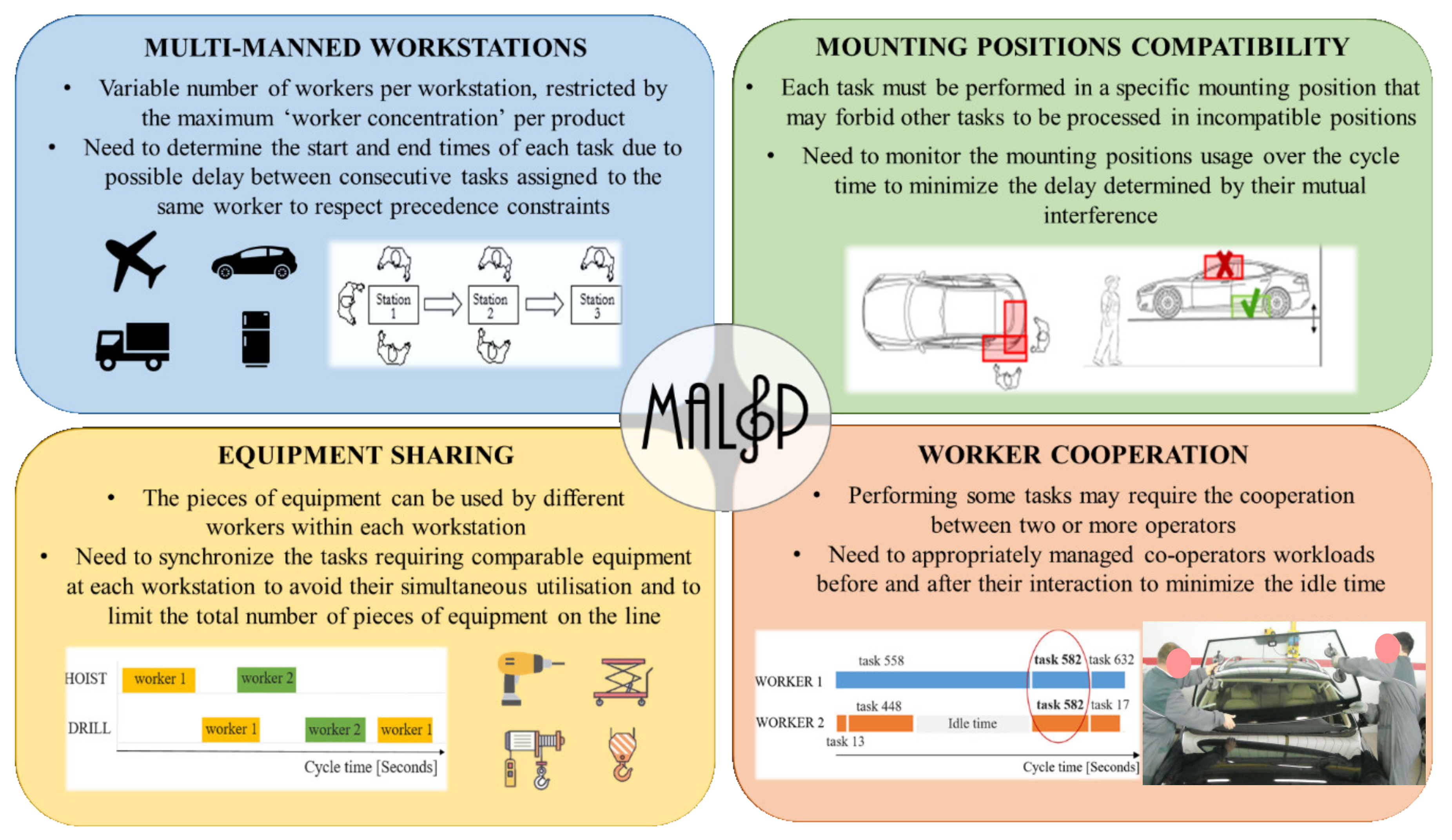
Additional features are considered in this paper to achieve realistic task assignments, such as compatible mounting positions. For large products, the workpiece can be divided into several mounting positions and each task must be performed in a specific one. At any time, only one task can be executed in each mounting position (Figure 4a). Furthermore, performing a task in a specific mounting position can forbid other tasks to be processed in different incompatible positions (Figure 4b). Hence, it is necessary to monitor the mounting positions use over the cycle time to minimize the delay determined by their mutual interference.
Some additional limitations deal with the equipment employed, such as customized equipment performing certain tasks or expensive equipment. This scenario requires avoiding the duplication of comparable equipment between different workstations and their simultaneous utilization within a station by different operators. For this purpose, at each workstation, the tasks requiring the same equipment type should be properly scheduled. Finally, performing some tasks may need cooperation between two or more operators, e.g., windshield installation for cars. Thus, their workloads before and after this interaction need to be appropriately managed to enable effective cooperation while reducing the idle time as much as possible. Figure 5 summarizes the main characteristics described above and presents the framework for the MALS Problem addressed in this paper.
4. Methodology and Mathematical Model
This section presents the methodology adopted to develop a new MIP model for the version of MALSP addressed in this paper that leverages and further develops some aspects proposed in Ferrari et al. [38]. First, the proposed methodology suggests defining the indices of the model to develop, which represents the entities considered in the MALSP. Then, it is necessary to identify what are the decision variables. This step is very delicate since inadequate variable modeling would result in a problem difficult to be solved or with missing relevant aspects. Furthermore, the objective function has to be defined considering all the different performances of the assembly line that would be maximized, resulting in a probable trade-off among them. Finally, it is necessary to identify the set of the different constraints that should adequately model all the peculiarities of the considered problem.
In particular, to solve this problem, the required decisions concern the total number of workstations, the number of workers, and the equipment types allocated to them, the subset of tasks assigned to each worker, and the scheduling of these tasks during the cycle time. The objective proposed is to determine the optimal compromise between minimizing the total number of workers on the line, the workstation number, and the workload variation between operators. In the presented model, the following assumptions are considered. Mass production of one homogeneous product on a serial line layout is taken into account with a fixed and constant cycle time. Product assembly has J tasks to be processed. Each task has a processing time tj, which is deterministic and independent from the assigned workstation.
The following paragraph presents the model indices, decision variables, and parameters. Indices are adopted to represent the sets of tasks (j, h = 1, .., J), workers (w, v = 1, .., W), workstations (k = 1, .., K), mounting positions (l, f = 1, .., L) and equipment types (e = 1, .., E) of the multi-manned assembly. The MALSP requires some decision variables in addition to the traditional task to worker assignment xjw and the workstation opening rk, such as the workstation equipment yek, the worker to workstation belonging zwk, the task starting time sj, and the tasks sequencing ujh. The latter two variables are instrumental in managing the scheduling problem arising in the synchronization of tasks. Moreover, each task j is distinguished by the predecessor tasks phj, in addition to other parameters specific to the problem under study that include the equipment needed bje, the number of workers required gj, and its mounting position djl. The maximum number of workers per workstation M and the maximum number of pieces of equipment for each type e on the line Ne are two key criteria to be set by the assembly line designer depending on the considered case study. Indeed, they have to fulfill certain preconditions, such as the compatibility with the product size and structure, the workstation layout, and the equipment costs. Similarly, the incompatibility between mounting positions alf determines whether different workers can simultaneously occupy positions i and j during the performance of their tasks.
4.1. Indices
j, h index for task j, h = 1, .., J;
w, v index for worker w, v = 1, .., W;
k index for workstation k = 1, .., K;
l, f index for mounting position l, f = 1, .., L;
e index for equipment type e = 1, .., E.
4.2. Decision Variables
xjw
zwk=
yek=
rk=
ujh=
sj= .
4.3. Parameters
c, [time unit]
tj, [time unit]
gj, [workers]
phj=.
bje=
djl=
alf=
M [workers];
Ne [equipment].
4.4. Objective Function
The objective function, considered to evaluate the performance of a synchronization solution, aims to reduce both the number of workers on the line, the number of multi-manned workstations and to distribute workloads to workers as fairly as possible. It is based on three different key criteria. First, the line efficiency (LE) is the ratio of the time required to perform all assembly tasks to the total time available, as shown in Equation (1). It depends on the number of workers and the actual cycle time on the line (TMAX), i.e., the longest working time among the workers as defined in Equation (2). The second contribution is line length (LN), which is equal to the number of workstations (Equation (3)). Finally, the smoothness index (SI) considers the balance of the generated workloads and is given by Equation (4). These parameters are combined together to build the proposed objective function (Equation (5)), which is a non-dimensional amount greater than 1 to be minimized. It is calculated as the product of the three contributions given by the ratio between LE, LN, and SI and their most desirable values, which are LEmax, LNmin, and SImin, respectively. These serve to compare quantities with different measurement units using identical weights and they are defined by Equations (6)–(8), as a solution with 100% LE, minimum LN given by Equation (7), and SI tending to 0 (calculated as an objective fraction S of the cycle time) represent a perfectly synchronized line.
4.5. Constraints
Concerning the model constraints, those stated by the Equations (9)–(12) characterize the majority of ALB problems. Constraint (9) ensures that each worker belongs exclusively to one station. Constraint (10) fastens the tasks to be assigned only to the workers that belong to any workstation. Constraints (11) and (12) are the workstation opening decision constraints. Constraint (12) ensures that workstations are loaded in an increasing manner noting the sequence of the workstation indices. Constraints (13) and (14) limit the task processing period. The former ensures that any assembly operation has to be finished within the cycle time; the latter guarantees the precedence relations among the tasks.
In the case of large product assembly, it is possible that some tasks require cooperation between two or more workers for their execution. Thus, constraint (15) forces each task to be assigned uniquely to the number of workers needed to perform the task, ensuring that these workers belong to the same workstation.
Constraints (16) and (17) are about equipment requirements. Constraint (16) allows a task to be executed in a workstation only if it is equipped properly. Constraint (17) manages the feasibility of the equipment sharing since it enables the installation of a maximum of one unit of each equipment type in every individual workstation.
Constraints (18) and (19) consider the layout restrictions in which the line has to be installed, and the assembly system designer preferences. They guarantee that the maximum number of workers and the maximum number of each equipment type are not exceeded in any workstation.
Constraints (20) and (21) ensure the feasibility of the synchronization, considering that different workers at the same station can execute several tasks simultaneously on a product and each of these tasks has specific technological predecessors. Constraint (20) guarantees that two tasks cannot precede each other simultaneously. Constraint (21) limits the decision variable ujh to 0 if there is no parallelism between tasks i and h in the examined workstation. Constraint (22) ensures that each worker can handle one task at a time. For the duration of any task in a specific mounting position, constraint (23) disables the execution of all the tasks that involve incompatible mounting positions.
Finally, constraints (24)–(28) show the integer variables. Constraint (29) indicates that the start time of every task should be non-negative.
5. Proposed Simulated Annealing-Based Procedure
Due to its computational complexity, the MALSP is strongly NP-hard, and the mathematical programming model previously described in Section 4 can solve only small instances of the problem. In contrast, medium- and large-size scales of the MALSP need heuristic-based procedures to be handled. Several meta-heuristic procedures could be adopted to define a feasible and good solution to this optimization model. Among the most promising ones, it is necessary to mention ant colony, genetic, and simulated annealing algorithms. All these possibilities are distinguished by strengths and weaknesses that should be carefully assessed before deciding which to adopt. Considering the features of the developed MALBP, it is of major importance that the selected meta-heuristic algorithm offers the opportunity to quickly converge to feasible and good solutions for the targeted problem. A remarkable advantage of simulated annealing (SA) in terms of its usage to solve this MALBP is represented by the fact that all the intermediate solutions defined in its following steps of the SA procedure are feasible [38], e.g., represent tasks to stations assignment that fulfill all the problem constraints. This feature is of extreme importance to eliminate time-consuming procedures required to assess the feasibility of intermediate solutions, eliminate unfeasible ones and eventually identify alternative configurations. Defining a specific SA deals with setting the encoding of alternatives and the first solution, along with the way to obtain a feasible synchronization configuration, the neighborhood generation, and the objective function adopted to evaluate the solutions found. Those elements are described in detail in the following of this section.
5.1. Solutions Encoding and Initial Solution
In the proposed SA procedure, each solution is coded by a priority list of the tasks (PL) that determines how they are selected to be assigned to the multi-manned workstations. The PL used to build the initial solution is particularly relevant since it affects the running time of the procedure. Thus, several preliminary experiments have been conducted with different methods for assigning priority values to tasks (such as the ranked positional weights (RPW), the largest candidate rule, and the task enumeration proposed by Özcan and Toklu [39]). They have shown how the RPW yields the best performance. According to this mechanism, for each task j, the RPW value is calculated by summing the duration for all its following tasks, task j itself included. Then, the tasks are sorted in descending order of RPW. Priority values from n to 1 are uniquely assigned to tasks ensuring no ambiguity. In the case of tasks with the same RPW, the highest priority value is given to the one with the lowest enumeration.
5.2. Building a Feasible Solution
For obtaining a feasible line synchronization solution, the procedure opens one workstation at a time, and it determines the number of workers and the pieces of equipment allocated to it and the set of sequencing tasks ascribed to each worker until all tasks are assigned in such a way that all constraints are fulfilled. These constraints consider the task precedence and occurrence, the cycle time respect, the compatibility among mounting positions simultaneously used, the effectiveness of workers cooperation, and the equipment sharing feasibility.
The presented algorithm consists of initialization and seven sequential steps, which are described in detail in the following section. The steps sequence and the decision-making path are shown in Figure 6.
5.2.1. Step 0. Initialization
Define the problem input data and the procedure parameters, such as the cycle time (c), the worker concentration (M), the maximum number of each piece of equipment (Ne), and the mounting position compatibility. For each task, it is necessary to define its duration (tj), its immediate predecessors, its mounting position, the necessary equipment, and the number of workers (gj) needed to execute it. Other procedure parameters are introduced in the following steps.
5.2.2. Step 1. Opening a New Multi-Manned Workstation
The worker number of the opening workstation equals M.
5.2.3. Step 2. Determine Available Task Sets and Their Starting Times
Task j is available if it fulfills all the constraints at a certain instant (sj) of the cycle time, which is called starting time. These constraints are expressed by Equations (13)–(16) and (23) of the model presented in the previous section. They include the following:
- -
- predecessors are assigned to earlier workstations or earlier time in the current workstation, and they are already completely executed (constraint express by Equation (14));
- -
- its mounting position is compatible with the mounting positions of the other processing tasks in the workstation (Equation (23));
- -
- pieces of equipment simultaneously employed by other workers of the workstation are not required (Equation (16));
- -
- gj workers are able to simultaneously execute the task (Equation (15));
- -
- the assignment of task j with a specific duration tj does not violate the cycle time (Equation (13)).
5.2.4. Step 3. Determine the Subset of Available Task with the Lowest Starting Time
If this set is empty, skip steps 4 and 5 of this algorithm.
5.2.5. Step 4. Select a Task
From the subset of available tasks having the lowest starting time, select the task distinguished by the highest priority value.
5.2.6. Step 5. Assign the Task to a Worker
Select the worker that can start to perform the task as early as possible. If more workers can start to work on the task at the same time, select the worker randomly.
5.2.7. Step 6. Assess the Generated Workload Efficiency
Accept the generated workload of the current multi-manned workstation if at least one of the following conditions is fulfilled:
(1) Number of workers in the workstation equals 1, as in Equation (30).
(2) Mean idle time (MI) of the workers in the current multi-manned workstation (Equation (31)) is not greater than a predetermined acceptable upper bound (UB), as in Equation (33). UB is the mean idle time per worker considering all tasks assigned to THL, i.e., the theoretical minimum number of workers on the line (Equation (24)), multiplied by a factor δ greater than 1 (Equation (32)).
(3) Accept the generated workload with certain probability random (0,1), indicated with XP (Equation (34)). This ensures the appropriate randomness of the procedure.
If the generated workload for the current workstation is not accepted, move to step 7. Otherwise, the set of unassigned tasks is checked. If this set is empty, a feasible synchronization solution is built. Otherwise, the procedure should return to step 1 to open a new multi-manned workstation.
5.2.8. Step 7. Revise the Variable Values
Un-assign all the tasks previously assigned to the current workstation. Decrease the number of workers in the current multi-manned workstation by one and proceed to step 2.
5.3. Neighborhood Generation
A neighbor to the current synchronization solution is obtained by a move in the priority list coding the current construction. The proposed SA procedure adopts the swap and inserts operators introduced by Ozcan and Toklu [39]. The methodology is in the following steps:
- Generate a random value p1 [0,1];
- If p1 ≤ 0.5, then proceed to step 4;
- Randomly select two different positions in PL and exchange their contents (i.e., priority values). Break;
- Randomly select a position in PL and insert its content left to another randomly selected position. Break.
An example of neighborhood generation by swapping and inserting operators for a PL with nine positions is shown in Figure 7.
5.4. Objective Function
The proposed procedure evaluates the generated synchronization solution in relation to three parameters, which are the line length (LN), the line efficiency (LE), and the smoothness index (SI). They are merged into a single objective function, as previously described in Equation (5).
6. Industrial Case Study
The customized SA procedure proposed is applied to a real assembly line dataset of a European manufacturer of luxury sports cars. The data have been collected on the field and provided directly by the company. A preprocessing phase has been carried out to ensure the necessary robustness and reliability to the adopted data, with double-checking both by the authors and the managers of the luxury sports car manufacturer.
In this section, paragraph 6.1 introduces the input data of such an industrial case study, whereas paragraph 6.2 proposes the calibration of the SA procedure parameters. Furthermore, all the input data for the considered case study are included in Tables S1–S5 in the Supplementary Materials of this manuscript since, as far as the Authors knowledge, they represent one of the biggest real industrial case study available in the literature of ALBPs.
6.1. Automotive Case Study Input Data
The data presented in the following paragraph are scaled to guarantee the confidentiality of data for the manufacturer. Indeed, the data proposed in this paper actually represent a real and operating assembly line of a very relevant luxury sports car located in Europe. To ensure the maximum confidentiality of such sensitive information, all the data have been altered adopting identical criteria and technical nomenclature have been modified to anonymous notions.
The number of tasks needed to complete the car assembly is equal to 665, and it is probably one of the largest presented in the literature so far, according to the authors’ knowledge. The total task time is about 29.65 h, and the required cycle time (c) for the line is equal to 5952 s. Another important input parameter is the maximum worker concentration per workstation (M). This is determined primarily by considering the product structure and size and the shop floor layout to be set to three workers. The task durations and the precedence constraints between tasks are attached to the paper as Supplementary Materials.
In addition, the mounting positions are identified for the considered product. As shown in Figure 8, four levels with different heights are adopted to perform tasks on the car. Each level could count up to 20 different mounting positions (5 × 4) from the top view. However, not every position is used to execute tasks and some of them are unusable; thus, the effective number of different mounting positions is 50. All of these generate interferences with other mounting positions. For instance, the car’s upper canopy can be assembled only when it is in the “low” position. In this case, the car has wheels on the ground, and it is not possible for workers to perform tasks involving the lower part of the car. Conversely, when the car is in the so-called top position, the workers are under the machine and can carry out tasks at the bottom. The mounting position of each task is exposed in the attached Supplementary Materials, in addition to the relationship between the positions. This is expressed through a matrix in which each individual element equals 1 if the corresponding mounting positions are compatible (i.e., can be simultaneously occupied by different workers performing their tasks) and 0 otherwise.
Some tasks require a particular type of equipment to be carried out. In this case study, 20 different equipment types are considered, and their allocation to workstations must be defined as an output of the solving procedure. The attached Supplementary Materials presents the pieces of equipment needed for the task execution and the maximum number of each equipment type that can be installed on the whole assembly line. Equipment names are not given for confidentiality reasons, and they are indicated by letters from A to T.
Finally, the Supplementary Materials provides the number of workers required to complete each task, which in this instance could be 1 or at most 2 if cooperation is needed. Table 1 is an abstract from such material and it shows all the input data that distinguish some tasks for sake of exemplification.
6.2. Calibration of the Simulated Annealing Parameters
The customized SA procedure proposed in Section 5 is applied to find the optimal synchronization solution for the MALSP suggested in the case study. It is developed in common coding software environment and experiments are carried out on a standard PC with a 2.30 GHz intel 7-4650U CPU and 8 GB RAM.
With reference to the case under study, the proposed procedure has been carefully tuned to define the most suitable values for the parameters adopted both for the control of the annealing process and for the building of new feasible solutions.
The control parameters needed are the initial and the final temperature ( and respectively), the cooling ratio (λ) and the so-called epoch length (K) (i.e., the number of neighborhood searches at each temperature level). Their ranges are determined based on the previous and similar literature contributions and their specifications. To evaluate the effects of each parameter on the procedure results, some preliminary experiments have been conducted following the design of experiment principles. As a result of this process, and . are set to 21 and 1.5, respectively. In this way, at a specific iteration, the probability of accepting solutions that are worse than the current ones is initially high and progressively drops to lower values while the procedure is running, in accordance with the adopted objective function. λ and K are set at 0.90 and 50, respectively, to ensure a proper cooling rate and an appropriate neighborhood search at each temperature level.
The parameters employed to build feasible solutions are δ and (see paragraph 5.2, step 6). They are set at 40 and 15, correspondingly. Moreover, the smoothness index target value (SImin) needs to be configured to give proportional weights to all the contributions of the objective function used to evaluate solutions (Equation (5)). This parameter depends on factor S as previously shown in Equation (8), which has been fixed at 3% of the cycle time for the examined instance. Table 2 summarizes the parameter values selected for the considered case study.
Setting parameters deeply influences the execution of the procedure and the number of iterations (i.e., the number of feasible solutions generated during the annealing process) needed to achieve the optimal solution. Figure 9 shows the objective function values in relation to the number of iterations performed. Initially, even very poor solutions are easily accepted, but as the number of iterations increases, only smaller worsening can be embraced. Moreover, the objective function improvements obtained through the iterations are highlighted in the figure. Good values are gained from the first procedure iteration (objective function equal to 3.50) due to the initial priority list selection according to the RPW method. The best result (objective function equal to 1.74) is achieved at the 449th feasible synchronization solution generation with a computational time of 4086 s by using the abovementioned PC. This optimal solution for the case study is illustrated in detail in the following section, discussing its main features.
7. Results and Discussion
This section presents the results and discussion of the developed research. In particular, sub-Section 7.1 focuses on the results obtained adopting the proposed MALBP and the related SA algorithm to solve the presented case study of an automotive multi-manned assembly line, whereas sub-Section 7.2 proposes a discussion comparing the solution obtained by developed models and methods to the one achievable with the most promising and relevant literature contributions distinguished by similar features and applications.
7.1. Results
The case study previously presented is solved by applying the customized SA procedure proposed in this paper. The obtained results are analyzed in this sub-section. The optimal objective function value (Equation (5)) found is equal to 1.74. This indicator represents the overall goodness of the solution summarizing three of its main aspects. One of these is the line efficiency (LE, Equation (2)), equal to 89.85%. Strictly related with this, the number of workers of the line amounts to 20, while its lower bound is 18. This theoretical number is determined assuming that there are no constraints of any type to complete all assembly tasks. Another key feature is the line length (LN, Equation (3)), which is equal to 10 workstations. The lower bound of this indicator is seven since the maximum worker concentration per workstation is three. The third purpose of the proposed model is the minimization of the workload variation among assembly line workers, which is represented by the smoothness index (SI, Equation (4)). In the obtained solution, it is equal to 168 s and corresponds to 3% of the average workload of an individual worker, which is 5338 s. Table 3 summarizes the main features of the presented solution for the MALSP case study.
The optimal solution for the considered case study indicates that the number of workers ranges from one to three at each multi-manned workstation. The possibility of assigning a variable worker number to workstations ensures high flexibility to the proposed synchronization. Moreover, the equipment needed at each multi-manned workstation is valuable information for the considered case study. The proposed procedure determines the equipment to install in each individual workstation. Furthermore, it manages its utilization by the workers during the cycle time to avoid any possible simultaneous adoption through the synchronization of their employment with task execution. In the obtained solution, just four pieces of equipment out of 20 (F, D, H, and I) are duplicated in two different workstations, and no equipment is assigned to more than two workstations. Figure 10 illustrates the workers to stations assignment, their saturation, and the equipment provided to each workstation. Moreover, even if the synchronization required for ensuring the solution feasibility tends to increase the idle time among tasks and reduce workers saturation, it averages 89.7% and it is high for all workers as its minimum is 77%, which is representative of the last worker on the line (Figure 10).
Workbooks providing all the information that workers need to complete their assembly assignments over a cycle time could be valuable and useful tools in manufacturing companies. The proposed procedure is designed to automatically define for each worker the optimal sequence of tasks to perform, along with the equipment to use, the mounting position to adopt, and whether cooperation with other workers is required for every instant of the cycle time. Indeed, the start and end processing times of each task are specified to ensure scheduling feasibility. Table 4 illustrates the workbook recommended for Worker 1 at Workstation II as an example. Using it as a support, the worker knows in detail what he is expected to do at every instant of the cycle time. Moreover, all the task sequences assigned to workers are provided in the Supplementary Materials.
If some cooperation between workers is involved, a certain amount of idle time may arise between tasks when workers do not simultaneously complete the tasks previously assigned to them. Aiming to reduce these idle times and enable cooperation, the proposed procedure specifies the time when workers are expected to perform tasks together during the cycle time through proper synchronization of their workloads. Figure 11a shows the cooperation between Workers 1 and 2 of Workstation II as an example. They cooperate for part of the cycle time (from 3410 s to 3530 s) to complete task 582 and then resume their work individually.
Tracking of mounting position and equipment usage throughout the entire cycle time is necessary to provide a feasible task assignment to workers at each individual workstation. This monitoring allows to defining exactly when tasks can start to be processed because all constraints are fulfilled. For sake of exemplification, Figure 11b shows the mounting position HIGH_12 occupation in Workstation II over a portion of the cycle time. Worker 2 can start task 253 execution in HIGH_12 after completion of task 531 by Worker 1 in the same mounting position to avoid overlap. Similarly, Figure 11c illustrates the utilization of the pieces of equipment assigned to Workstation II. The proposed procedure considers the non-duplication of equipment within a workstation as a constraint. Indeed, only one copy of each piece of equipment is allocated to Workstation II because it is shared by workers who use it at different times. The piece of equipment R is employed first by Worker 1 to perform task 240 and only later by Worker 2 to complete task 70. The same applies to the piece of equipment G.
7.2. Discussion
This sub-section proposes a comparison between the results obtained by the MALBP and related SA solving algorithm proposed in this manuscript and the most promising literature contributions that target similar assembly line-related problems. In particular, the literature is distinguished by a set of different original contributions that consider several features of MALBPs very relevant to adequately model a real industrial assembly system. However, their main limitation is represented by the problem dimension of the analyzed case studies, which is often insufficient in terms of task number. Indeed, only two of them face the challenges determined by big size problems, namely Bartholdi [13] and Lee et al. [40]. They propose two case studies with more than 100 tasks, the largest available in the literature so far. On the contrary, this paper offers a novel practical problem distinguished by 665 tasks, which may be considered the biggest available in the literature for multi-manned assembly lines. This dataset offers unique opportunities to researchers who are willing to validate novel models and methods with very large and real case studies.
Furthermore, the considered instances proposed by Bartholdi [13] and Lee et al. [40] are distinguished only by few specific features of MALBPs; in particular, they lack to consider both the equipment that needed to execute certain tasks and the workpiece different mounting positions. The two features often distinguish real-world case studies and should not be neglected. The MALBP proposed in this manuscript fully considers these aspects and the related consequences, e.g., the need for a meta-heuristic algorithm as the presented SA to solve the complex optimization problem.
The remarkable assembly workers average saturation rate of 82% obtained by Bartholdi [13] is even improved by the model and procedure developed in this manuscript and adopted to solve the presented case study to a value of 89% despite considering as constrains additional limitations, such as mounting position restrictions, equipment sharing, and worker cooperation within the same station.
8. Conclusions
This paper considers the assembly process of large products requiring the execution of a great number of tasks, such as cars, trucks, buses, white goods, and automatic machines. Their assembly systems are characterized by lines with multi-manned workstations, which increase the balancing problem complexity. Indeed, the start/end processing time of each task must be determined and some idle time may arise even between tasks assigned to the same worker. Thus, proper workload synchronization is necessary to obtain feasible solutions to this problem. Moreover, other features typifying multi-manned assembly lines are the cooperation between workers to perform tasks together, the relationship of compatibility-incompatibility among mounting positions, and the equipment sharing between workers of the same workstation. Although the here-defined multi-manned assembly lines synchronization problem (MALSP) is crucial for many real production systems, the literature on this field is not abundant.
Hence, a new mixed-integer programming model for this specific MALSP is presented. The objective of this model is to found an optimal compromise between maximizing the line efficiency and minimizing both the number of workstations and the workload variation between workers, addressing all the aspects briefly aforementioned.
Since this problem is well known as NP-hard, a customized simulated annealing procedure is proposed to solve it efficiently within a reasonable computational time.
A case study of a European manufacturer of luxury sports cars is introduced to examine the performance and the validity of and the proposed MIP model and SA procedure. According to the authors’ knowledge, this is one of the largest presented in the literature so far since this car assembly requires the execution of 665 tasks. It also includes most of the complexities typifying these industrial environments, as proper synchronization of tasks is required to ensure the precedence technological constraints respect, the absence of overlaps in the use of equipment and mounting positions over the cycle time, and an effective cooperation between workers.
The parameters of the SA procedure are appropriately calibrated for this specific case study. The presented solution is obtained after 449 iterations (i.e., feasible solutions generated). It counts 20 workers spread over 10 workstations, and a percentage of 89.85% represents the line efficiency, while the smoothness index is 3% of the average workload per worker. Comparison of these performance indicators with their lower bounds shows that the procedure performs very well and it is suitable for industrial applications with a large number of tasks. In addition, the proposed procedure identifies the synchronized tasks sequence assigned to each worker, the mounting positions occupation, the equipment uses, and the presence of cooperation over the entire cycle time. These results are very useful in practice for companies that aim to design the assembly system of a product, in terms of the number of workstations and equipment allocation, in addition to organizing the workforce as effectively as possible.
Further research should integrate this problem by taking into account mixed-model assembly lines since the market requires a large product variety due to mass customization. Finally, given the predominance of manual tasks in assembly processes, the extension of the MALSP to include aspects of workers’ ergonomics can be considered as another area of future study in this field.
Supplementary Materials
The following are available online at https://www.mdpi.com/2076-3417/11/6/2523/s1, Table S1: Key input data set for each task in the presented industrial case study, Table S2: Precedence matrix, Table S3: Compatibility-incompatibility among mounting positions matrix, Table S4: Maximum number of each equipment type on the whole line in the presented industrial case study, Table S5: Task sequence assignment to workers in the optimal solution obtained.
Author Contributions
Conceptualization, F.P., M.G. and E.F.; methodology, F.P. and M.G.; software, F.P. and S.M.; validation, S.M.; formal analysis S.M.; investigation, F.P.; resources, M.G.; data curation, S.M.; writing—original draft preparation, F.P. and S.M.; writing—review and editing, F.P.; visualization, F.P.; supervision, E.F. All authors have read and agreed to the published version of the manuscript.
Funding
This research received no external funding.
Institutional Review Board Statement
Not applicable.
Informed Consent Statement
Not applicable.
Conflicts of Interest
The authors declare no conflict of interest.
References
- Cohen, Y.; Faccio, M.; Pilati, F.; Yao, X. Design and management of digital manufacturing and assembly systems in the Industry 4.0 era. Int. J. Adv. Manuf. Technol. 2019, 105, 3565–3577. [Google Scholar] [CrossRef] [Green Version]
- Alghazi, A.; Kurz, M.E. Mixed model line balancing with parallel stations, zoning constraints, and ergonomics. Constraints 2018, 23, 123–153. [Google Scholar] [CrossRef]
- Mas, F.; Ríos, J.; Menéndez, J.L.; Gómez, A. A process-oriented approach to modeling the conceptual design of aircraft assembly lines. Int. J. Adv. Manuf. Technol. 2013, 67, 771–784. [Google Scholar] [CrossRef]
- Faccio, M.; Ferrari, E.; Gamberi, M.; Pilati, F. Human Factor Analyser for work measurement of manual manufacturing and assembly processes. Int. J. Adv. Manuf. Technol. 2019, 103, 861–877. [Google Scholar] [CrossRef]
- Bortolini, M.; Faccio, M.; Gamberi, M.; Pilati, F. Motion Analysis System (MAS) for production and ergonomics assessment in the manufacturing processes. Comput. Ind. Eng. 2020, 139, 105485. [Google Scholar] [CrossRef]
- Cohen, Y.; Naseraldin, H.; Chaudhuri, A.; Pilati, F. Assembly systems in Industry 4.0 era: A road map to understand Assembly 4.0. Int. J. Adv. Manuf. Technol. 2019, 105, 4037–4054. [Google Scholar] [CrossRef]
- Kucukkoc, I.; Zhang, D.Z. Integrating ant colony and genetic algorithms in the balancing and scheduling of complex assembly lines. Int. J. Adv. Manuf. Technol. 2016, 82, 265–285. [Google Scholar] [CrossRef] [Green Version]
- Scholl, A. Balancing and Sequencing of Assembly Lines. Contrib. Manag. Sci. 1999. [Google Scholar] [CrossRef]
- Scholl, A.; Becker, C. State-of-the-art exact and heuristic solution procedures for simple assembly line balancing. Eur. J. Oper. Res. 2006, 168, 666–693. [Google Scholar] [CrossRef]
- Gómez, A.; Ríos, J.; Mas, F.; Vizán, A. Method and software application to assist in the conceptual design of aircraft final assembly lines. J. Manuf. Syst. 2016, 40, 37–53. [Google Scholar] [CrossRef]
- Al-Hawari, T.; Ali, M.; Al-Araidah, O.; Mumani, A. Development of a genetic algorithm for multi-objective assembly line balancing using multiple assignment approach. Int. J. Adv. Manuf. Technol. 2014, 77, 1419–1432. [Google Scholar] [CrossRef]
- Sivasankaran, P.; Shahabudeen, P. Modelling hybrid single model assembly line balancing problem. Udyog Pragati 2013, 37, 26–36. [Google Scholar]
- Bartholdi, J.J. Balancing two-sided assembly lines: A case study. Int. J. Prod. Res. 1993, 31, 2447–2461. [Google Scholar] [CrossRef]
- Dimitriadis, S.G. Assembly line balancing and group working: A heuristic procedure for workers’ groups operating on the same product and workstation. Comput. Oper. Res. 2006, 33, 2757–2774. [Google Scholar] [CrossRef]
- Gansterer, M.; Hartl, R.F. One- and two-sided assembly line balancing problems with real-world constraints. Int. J. Prod. Res. 2017, 56, 3025–3042. [Google Scholar] [CrossRef] [Green Version]
- Baykasoglu, A.; Dereli, T. Two-sided assembly line balancing using an ant-colony-based heuristic. Int. J. Adv. Manuf. Technol. 2006, 36, 582–588. [Google Scholar] [CrossRef]
- Wang, Q.; Sowden, M.; Mileham, A.R. Modelling human performance within an automotive engine assembly line. Int. J. Adv. Manuf. Technol. 2013, 68, 141–148. [Google Scholar] [CrossRef]
- Lapierre, S.D.; Ruiz, A. Balancing assembly lines: An industrial case study. J. Oper. Res. Soc. 2004, 55, 589–597. [Google Scholar] [CrossRef]
- Bortolini, M.; Faccio, M.; Gamberi, M.; Pilati, F. Multi-objective assembly line balancing considering component picking and ergonomic risk. Comput. Ind. Eng. 2017, 112, 348–367. [Google Scholar] [CrossRef]
- Hoffmann, T.R. Assembly Line Balancing with a Precedence Matrix. Manag. Sci. 1963, 9, 551–562. [Google Scholar] [CrossRef]
- Çevikcan, E.; Durmuşoğlu, M.B.; Unal, M.E. A team-oriented design methodology for mixed model assembly systems. Comput. Ind. Eng. 2009, 56, 576–599. [Google Scholar] [CrossRef]
- Pearce, B.W.; Antani, K.; Mears, L.; Funk, K.; Mayorga, M.E.; Kurz, M.E. An effective integer program for a general assembly line balancing problem with parallel workers and additional assignment restrictions. J. Manuf. Syst. 2019, 50, 180–192. [Google Scholar] [CrossRef]
- Becker, C.; Scholl, A. Balancing assembly lines with variable parallel workplaces: Problem definition and effective solution procedure. Eur. J. Oper. Res. 2009, 199, 359–374. [Google Scholar] [CrossRef]
- Roshani, A.; Roshani, A.; Roshani, A.; Salehi, M.; Esfandyari, A. A simulated annealing algorithm for multi-manned assembly line balancing problem. J. Manuf. Syst. 2013, 32, 238–247. [Google Scholar] [CrossRef]
- Fattahi, P.; Roshani, A.; Roshani, A. A mathematical model and ant colony algorithm for multi-manned assembly line balancing problem. Int. J. Adv. Manuf. Technol. 2010, 53, 363–378. [Google Scholar] [CrossRef]
- Talbot, F.B.; Patterson, J.H. An Integer Programming Algorithm with Network Cuts for Solving the Assembly Line Balancing Problem. Manag. Sci. 1984, 30, 85–99. [Google Scholar] [CrossRef]
- Yilmaz, H.; Yilmaz, M. Note to: A mathematical model and ant colony algorithm for multi-manned assembly line balancing problem. Int. J. Adv. Manuf. Technol. 2016, 89, 1935–1939. [Google Scholar] [CrossRef]
- Kellegöz, T.; Toklu, B. A priority rule-based constructive heuristic and an improvement method for balancing assembly lines with parallel multi-manned workstations. Int. J. Prod. Res. 2014, 53, 736–756. [Google Scholar] [CrossRef]
- Kellegöz, T. Assembly line balancing problems with multi-manned stations: A new mathematical formulation and Gantt based heuristic method. Ann. Oper. Res. 2016, 253, 377–404. [Google Scholar] [CrossRef]
- Chen, Y.-Y.; Cheng, C.-Y.; Li, J.-Y. Resource-constrained assembly line balancing problems with multi-manned workstations. J. Manuf. Syst. 2018, 48, 107–119. [Google Scholar] [CrossRef]
- Roshani, A.; Nezami, F.G. Mixed-model multi-manned assembly line balancing problem: A mathematical model and a simulated annealing approach. Assem. Autom. 2017, 37, 34–50. [Google Scholar] [CrossRef]
- Rekiek, B.; Dolgui, A.; Delchambre, A.; Bratcu, A. State of art of optimization methods for assembly line design. Annu. Rev. Control. 2002, 26, 163–174. [Google Scholar] [CrossRef]
- Bukchin, J.; Tzur, M. Design of flexible assembly line to minimize equipment cost. IIE Trans. 2000, 32, 585–598. [Google Scholar] [CrossRef]
- Boysen, N.; Fliedner, M.; Scholl, A. Assembly line balancing: Which model to use when? Int. J. Prod. Econ. 2008, 111, 509–528. [Google Scholar] [CrossRef]
- Nicosia, G.; Pacciarelli, D.; Pacifici, A. Optimally Balancing Assembly Lines with Different Work-stations. Discret. Appl. Math. 2002, 118, 99–113. [Google Scholar] [CrossRef]
- Ege, Y.; Azizoglu, M.; Ozdemirel, N.E. Assembly line balancing with station paralleling. Comput. Ind. Eng. 2009, 57, 1218–1225. [Google Scholar] [CrossRef]
- Ogan, D.; Azizoglu, M. A branch and bound method for the line balancing problem in U-shaped assembly lines with equipment requirements. J. Manuf. Syst. 2015, 36, 46–54. [Google Scholar] [CrossRef]
- Ferrari, E.; Faccio, M.; Gamberi, M.; Margelli, S.; Pilati, F. Multi-manned assembly line synchronization with compati-ble mounting positions, equipment sharing and workers cooperation. IFAC-PapersOnLine 2019, 52, 1502–1507. [Google Scholar] [CrossRef]
- Özcan, U.; Toklu, B. Balancing of mixed-model two-sided assembly lines. Comput. Ind. Eng. 2009, 57, 217–227. [Google Scholar] [CrossRef]
- Lee, T.O.; Kim, Y.; Kim, Y.K. Two-sided assembly line balancing to maximize work relatedness and slackness. Comput. Ind. Eng. 2001, 40, 273–292. [Google Scholar] [CrossRef]
Figure 1.
Configuration of (a) simple, (b) two-sided, and (c) multi-manned assembly line.

Figure 2.
Example of precedence diagram.

Figure 3.
Task assignment comparison between (a) single-manned and (b) multi-manned assembly line balancing problems (ALBPs).
Figure 3.
Task assignment comparison between (a) single-manned and (b) multi-manned assembly line balancing problems (ALBPs).

Figure 4.
Mounting position constraint due to mutual interference, top view (a) and side view (b).

Figure 5.
The framework of the multi-manned assembly line synchronization problem (MALSP).

Figure 6.
Building a feasible solution for the multi-manned assembly line synchronization problem.

Figure 7.
Swapping and inserting operators.

Figure 8.
Car mounting positions identification.

Figure 9.
Objective function trend and improvement over the number of SA iterations.

Figure 10.
Equipment, number of workers, and their saturation for each workstation.

Figure 11.
Examples of the real-world constraints in the assembly line synchronization. (a) An example of collaboration between two workers in the same workstation; (b) Mounting position HIGH_12 scheduling at workstation II; (c) Pieces of equipment scheduling at workstation II.
Figure 11.
Examples of the real-world constraints in the assembly line synchronization. (a) An example of collaboration between two workers in the same workstation; (b) Mounting position HIGH_12 scheduling at workstation II; (c) Pieces of equipment scheduling at workstation II.


Table 1.
Example of input data for some assembly tasks.
| Task [#] | Duration [S] | Mounting Position | Equipment Required | Number of Simultaneous Workers [#] |
|---|---|---|---|---|
| 1 | 67 | MED_6 | - | 1 |
| 59 | 114 | LOW_1 | D | 1 |
| 348 | 276 | MED_13 | M | 2 |
| 608 | 1037 | TOP_8 | R | 1 |
| … | … | … | … | … |
Table 2.
Simulated annealing (SA) parameter values for the considered case study.
| Parameter | Notation | Value |
|---|---|---|
| Cooling ratio | Λ | 0.90 |
| Epoch length | K | 50 |
| Initial temperature | 21° | |
| Final temperature | 1.5° | |
| Multiplier | Δ | 40 |
| Probability of acceptance | 15% | |
| Cycle time fraction of SImin | S | 3% |
Table 3.
Main features of the proposed optimal solution.
| Performance Indicator | Value |
|---|---|
| Objective function | 1.74 |
| Number of workers | 20 |
| Number of workstations | 10 |
| Line efficiency | 89.85% |
| Smoothness index | 168 [s] |
Table 4.
Example of an assembly line worker workbook.
| Workbook of Worker 1 in Workstation II | |||||
|---|---|---|---|---|---|
| Task ID | Start Time [S] | End Time [S] | Mounting Position | Equipment Needed | Collaboration |
| 446 | 0 | 225 | HIGH_13 | - | no |
| 78 | 226 | 607 | LOW_1 | G | no |
| 80 | 608 | 676 | LOW_1 | - | no |
| 466 | 677 | 908 | HIGH_12 | - | no |
| 473 | 909 | 972 | MED_4 | - | no |
| 73 | 973 | 1214 | HIGH_12 | - | no |
| 240 | 1215 | 1339 | HIGH_12 | R | no |
| 531 | 1340 | 1397 | HIGH_12 | - | no |
| 558 | 1398 | 3409 | LOW_1 | - | no |
| 582 | 3410 | 3530 | LOW_1 | - | with Worker 2 |
| 632 | 3531 | 3671 | LOW_1 | F | no |
| 563 | 3672 | 3778 | LOW_1 | - | no |
| 279 | 3779 | 3865 | HIGH_12 | - | no |
| 277 | 3866 | 3905 | MED_13 | - | no |
| 66 | 3906 | 3997 | HIGH_12 | - | no |
| 84 | 3998 | 4062 | HIGH_12 | - | no |
| 82 | 4086 | 4217 | HIGH_12 | - | no |
| 104 | 4218 | 4240 | TOP_3 | - | no |
| 120 | 4241 | 4293 | TOP_2 | - | no |
| 127 | 4294 | 4481 | TOP_2 | - | no |
| 138 | 4482 | 4599 | TOP_2 | - | no |
| 143 | 4600 | 4743 | TOP_2 | - | no |
| 137 | 4744 | 4812 | TOP_2 | - | no |
| 648 | 4813 | 5113 | HIGH_8 | - | no |
| 431 | 5114 | 5148 | MED_12 | - | no |
| 583 | 5149 | 5338 | LOW_1 | - | with Worker 2 |
| 69 | 5339 | 5585 | HIGH_12 | - | no |
| 103 | 5586 | 5650 | TOP_3 | - | no |
Publisher’s Note: MDPI stays neutral with regard to jurisdictional claims in published maps and institutional affiliations. |
© 2021 by the authors. Licensee MDPI, Basel, Switzerland. This article is an open access article distributed under the terms and conditions of the Creative Commons Attribution (CC BY) license (http://creativecommons.org/licenses/by/4.0/).
Share and Cite
MDPI and ACS Style
Pilati, F.; Ferrari, E.; Gamberi, M.; Margelli, S. Multi-Manned Assembly Line Balancing: Workforce Synchronization for Big Data Sets through Simulated Annealing. Appl. Sci. 2021, 11, 2523. https://doi.org/10.3390/app11062523
AMA Style
Pilati F, Ferrari E, Gamberi M, Margelli S. Multi-Manned Assembly Line Balancing: Workforce Synchronization for Big Data Sets through Simulated Annealing. Applied Sciences. 2021; 11(6):2523. https://doi.org/10.3390/app11062523
Chicago/Turabian StylePilati, Francesco, Emilio Ferrari, Mauro Gamberi, and Silvia Margelli. 2021. "Multi-Manned Assembly Line Balancing: Workforce Synchronization for Big Data Sets through Simulated Annealing" Applied Sciences 11, no. 6: 2523. https://doi.org/10.3390/app11062523
Note that from the first issue of 2016, this journal uses article numbers instead of page numbers. See further details here.