Representing Virtual Transparent Objects on Optical See-Through Head-Mounted Displays Based on Human Vision


1
Graduate School of Information Science and Engineering, Ritsumeikan University, Kusatsu 525-8577, Shiga, Japan
2
Department School of Information Science and Engineering, Ritsumeikan University, Kusatsu 525-8577, Shiga, Japan
*
Author to whom correspondence should be addressed.
Appl. Sci. 2021, 11(2), 495; https://doi.org/10.3390/app11020495
Submission received: 19 November 2020
/
Revised: 24 December 2020
/
Accepted: 4 January 2021
/
Published: 6 January 2021
(This article belongs to the Special Issue X Reality Technologies, Systems and Applications)
Abstract
:In this study, we propose two methods for representing virtual transparent objects convincingly on an optical see-through head-mounted display without the use of an attenuation function or shielding environmental light. The first method represents the shadows and caustics of virtual transparent objects as illusionary images. Using this illusion-based approach, shadows can be represented without blocking the luminance produced by the real environment, and caustics are represented by adding the luminance of the environment to the produced shadow. In the second method, the visual effects that occur in each individual image of a transparent object are represented as surface, refraction, and reflection images by considering human binocular movement. The visual effects produced by this method reflect the disparities among the vergence and defocus of accommodation associated with the respective images. When reproducing the disparity, each parallax image is calculated in real time using a polygon-based method, whereas when reproducing the defocus, image processing is applied to blur each image and consider the user’s gaze image. To validate these approaches, we conducted experiments to evaluate the realism of the virtual transparent objects produced by each method. The results revealed that both methods produced virtual transparent objects with improved realism.
1. Introduction
Optical see-through head-mounted displays (OST-HMDs) are one of the more promising technologies for achieving augmented reality (AR). Recently, many consumer OST-HMDs, such as HoloLens (Microsoft, Redmond, WA, USA), Magic Leap One (Magic Leap, Plantation, FL, USA), and NrealLight (Nreal, Haidian, Beijing, China), have been released. In the research stage, OST-HMDs have been miniaturized to the scale of an ordinary glasses [1]. However, to the best of our knowledge there has been no similar miniaturization of video see-through HMDs (VST-HMDs).
OST-HMDs have a characteristic that allows users to observe the real world directly through a semi-transparent display. Consequently, such devices have the advantage of producing scenes with no time delay aside from the generated virtual objects and no blackout in user vision even when the HMD unexpectedly fails. However, these qualities make it difficult for OST-HMD systems to physically decrease the number of light rays that reach the retina from the real environment and allow a time delay between the image and the real world. Therefore, the realism of virtual objects that require attenuation or shielding from outside light decreases.
The aforementioned statement holds for transparent virtual objects (e.g., glass or liquid) that require a significant amount of shielding and attenuation for representation. Representation of transparent objects in computer graphics requires the rendering of optical phenomena such as refraction, reflection, shadow, and caustics [2]. Figure 1 shows the results produced by different displays representing a virtual transparent object in a real environment. The middle image shows the results produced by an ordinary display, whereas the right-hand image shows the results produced by a transmissive display such as an OST-HMD. The transmissive display image shows a virtual transparent object that is not partially optically consistent. However, the shadow and caustics are not accurately represented. To represent the shadow, it is necessary to reduce the luminance of the region in which the light of the environment is occluded by the virtual object. However, OST-HMDs cannot reduce the luminance of the shadow regions and, therefore, cannot accurately represent the light and dark patterns created by shadows and caustics. Another drawback is that the light rays produced by the real environment, which should be occluded by the virtual transparent object, penetrate it directly. Therefore, it is necessary to first erase the area of the real environment occluded by the object in order to accurately represent a virtual transparent object. Since OST-HMDs cannot completely rewrite the real environment, the virtual transparent object must be superimposed over the environment with light rays penetrating the object.
Another limitation that we faced when representing virtual transparent objects on stereoscopic displays such as HMDs is that the visual effects caused by eye movements must be reproduced. Real transparent objects must be represented by multiple images—a surface image produced by features such as dirt and a drawn pattern, a refracted image caused by distortion of the background, and a reflected image caused by the reflection of the surrounding environment. For each scenario, the distance between the eyes and the image differs, and the viewer focuses on each image selectively. In this process, the eyes converge (a process hereafter referred to as “vergence”) and the crystalline lenses adjust (hereafter referred to as “accommodation”) to enable clear viewing of the target [3]. As a result of the application of these visual functions, the appearance of transparent objects varies depending on the image. For example, while focusing on the surface of a transparent object, disparity and defocus occur in the refracted and reflected images as a result of mismatches between the vergence and accommodation points.
Conventional methods do not sufficiently reproduce these visual effects because of problems arising from computational cost and the mechanical properties of OST-HMDs. Reproducing the disparities between the transparent object images requires rendering for both eyes through the use of ray tracing methods. This incurs very high computational cost and cannot ensure the real-time representation required for AR. Furthermore, the vergence point for OST-HMD users is adjusted to the exact 3-D position of the virtual object but with the accommodation point fixed at the display focal plane (see Section 2 for details). This means that defocus between virtual objects with different depths does not occur naturally on such systems.
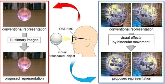
The purpose of this study was to improve the realism of the virtual transparent objects produced on OST-HMDs by taking the characteristics of human vision into account. We developed two display methods. The first method represents shadow and caustics using illusions that utilize the human characteristics of brightness perception. Specifically, shadow is pseudo-represented without decreasing the luminance of the real environment using a previously proposed method [4]. The caustics of transparent objects are calculated with the floor of the real environment taken into account and added to the shadow. The second method reproduces the visual effects caused by vergence and accommodation that occur when observing real transparent objects. In this method, the disparity caused by vergence and the defocus caused by accommodation are reproduced separately. Specifically, the disparity is reproduced by calculating the parallax of each image for both eyes in real time using a polygon-based calculation for representing the refraction. Simultaneously, the defocus is reproduced by applying blur processing to each image based on the gaze image in a process that takes the amount of blur in the human crystalline lens into account.
We experimentally confirmed that both methods could contribute to improving the realism of virtual transparent objects. In a preliminary experiment on shadow and caustics, we examined the perception of these features using an illusory image. Using this method, participants observed the shadow and caustics produced by two types of transparent objects with different shapes—a simple shape comprising a glass sphere and a more complex diamond shape. The results of the preliminary experiment suggested that, even if the shadow and caustics were represented using illusion, humans would perceive them in nearly the same manner as the phenomenon caused by physical effects. In the main experiment, participants evaluated the realism of virtual transparent objects directly. Specifically, they evaluated three types of virtual transparent objects based on different representations of shadow and caustics in two different environments. The experimental results indicated that both methods could represent virtual transparent objects more convincingly than the other types of representation. Additionally, we conducted an experiment on the reproduction of visual effects, wherein the participants evaluated the inherent realism of virtual transparent objects. They observed five types of virtual transparent objects produced using different visual effects while focusing alternately on different images. The experimental results indicated that the virtual transparent objects produced using the proposed method reproduced visual effects more convincingly than the images produced by using no visual effects. Subsequently, it was confirmed that the reproduction of disparities contributed more to the improvement of realism than defocusing.
The remainder of this paper is organized as follows. In Section 2, we introduce several studies on OST-HMDs that have enabled the visualization of virtual transparent objects with high realism as well as various studies on the representation of virtual transparent objects in stereoscopic vision. In Section 3, we describe the proposed method for generating the shadow and caustics of virtual transparent objects through illusion and discuss the results of its implementation. In Section 4, we present the experimental results that confirm the effectiveness of the method proposed in Section 3 in improving the realism of virtual transparent objects. In Section 5, we describe the proposed method for reproducing the visual effects of transparent objects and discuss the results of its implementation, and in Section 6 we present the experimental confirmation that this method is effective in improving the realism of image representation. In Section 7, we describe the limitations of our methods in light of the experimental results. Finally, in Section 8 we summarize the paper.
2. Related Work
2.1. Ost-Hmds Capable of Occluding the Real World
Conventional OST-HMDs such as HoloLens and Magic Leap One are incapable of attenuating the light arriving from the real environment. Therefore, these devices cannot accurately represent light and dark patterns created by shadow and caustics. Additionally, the virtual transparent objects produced by OST-HMDs are always brighter than the surroundings and are penetrated by the light rays present in the real environment.
The only way to attenuate or shield OST-HMDs is to use spatial light modulators (SLMs), which are electrically programmable devices that can modulate light at the pixel level. These include liquid crystal displays (LCDs), digital micromirror devices (DMD), and liquid crystal on silicon (LCOS) displays. Kiyokawa et al. [5,6] developed occlusion-capable OST-HMDs using LCDs. In their approach, the real environment is occluded by the placement of LCDs on the display focal plane following the formation of the image from the real environment on the focal plane. However, this approach adds to the bulk and weight of the device because it increases the optical path length. Furthermore, the fact that the depth of the real environment is fixed at the display focal plane limits the advantage of the OST-HMD system. Itoh et al. [7] developed the thinnest occlusion capable OST-HMDs system to date, wherein instead of increasing the optical path length, their system achieves occlusion by compensating the blur of the occlusion regions, which is accomplished by overlaying the texture of captured real environment onto the display.
Following a different approach, a system employing light fields has been proposed as a method for achieving occlusion [8,9]. This system can shield the light produced by the real environment at the light ray level. However, this system cannot currently be adapted to the use of a clear mask for occlusion because the image elements lack the proper resolution.
Although progress in the development of an occlusion-capable OST-HMD is certainly occurring, the use of SLMs can result in the loss of user vision in the event of a malfunction or failure. Accordingly, in this study, we attempted to develop a system for use with OST-HMDs without SLMs.
2.2. OST-HMDS Capable of Displaying at Optically Correct Depths
Conventional OST-HMDs are not capable of stereoscopic display at an optically correct depth. Specifically, when a virtual object with a certain depth is displayed by the OST-HMD, it is observed at the depth of the display focal plane and not at the intended depth. Consequently, the vergence position is correctly adjusted at the intended depth whereas the accommodation position is fixed at the depth of the display focal plane. This problem is called the vergence-accommodation conflict problem [10,11,12] and is the cause of the failure of OST-HMDs to reproduce the visual effects of transparent objects.
Numerous studies have been conducted to solve this problem. One such proposed method is the varifocal system [13,14,15]. This system enables us to set multiple focal planes for displaying virtual objects. It comprises a varifocal lens or mirror to shift the focal plane between near, medium, and far distances at high speed. However, the number of focal planes that can be set is currently limited by the slow update speeds of the image elements and varifocal lenses. Dunn et al. [13] developed a system that can project over a field of view (FoV) with variable focus by replacing the varifocal mirror with a half-mirror. However, the use a half-mirror-based optical design increases the system size.
Other systems that involve the use of light fields are cited in [16,17,18]. In such approaches, stereoscopic display is provided by reproducing light rays in 3-D space instead of displaying them on a surface display. In principle, light field-based systems can display virtual objects at any distance with optical correctness; however, they cannot currently display at high resolution because of the limited resolution offered by image elements on LCDs and electroluminescence displays (ELD). Additionally, they require significant computational cost, as the display function requires calculations based on ray-tracing instead of polygon-based algorithms.
2.3. Representation of Virtual Transparent Objects in Stereoscopic Vision
As described in Section 1, the rendering of virtual objects by OST-HMDs requires the reproduction of the optical phenomena of real transparent objects as accurately as possible. Langlotz et al. [19] proposed a color blending method to reduce the penetration of light from the environment into virtual objects. Their method achieves this by representing virtual objects with the color spectra of the environment taken into account and displaying the objects with colors similar to those of their real counterparts. By employing this method, the penetration of real light through virtual objects is reduced, making it possible to represent transparent objects more convincingly.
However, to the best of our knowledge there have been no studies on the representation of transparent objects using multiple images in an AR environment. The human ability to perceive virtual transparent objects can be significantly improved by representing them stereoscopically [20,21]. Chen et al. [21] suggested that the stereoscopic representation of virtual transparent objects is effective in enhancing the perception of the 3-D shapes of transparent objects. Further, it was observed that disparity is the most effective characteristic for accurate rendering. Owing to the limitations of the ray-tracing method used for rendering, these approaches could not reproduce visual effects in real time while considering the user’s gaze image. In the proposed method, real-time visualization is enhanced through the pseudo-representation of visual effects to take the gaze image into account.
Several methods have been proposed to reproduce the defocus of accommodation caused by differences in depth in AR environments [22,23]. Rompapas et al. [23] reproduced the pseudo-defocusing of accommodation in real time based on measurements of the user’s pupil diameter using an autorefractometer. In this study, we applied the results of these studies to dynamically blur the images of transparent objects though image processing to enable the consideration of the gaze image.
3. Representation of Shadow and Caustics
In this section, we propose a method for representing the shadows and caustics of virtual transparent objects by OST-HMDs, which are otherwise incapable of decreasing the luminance produced by the real environment. The results of this implementation are also discussed. OST-HMDs without SLMs cannot show light and dark patterns because they cannot attenuate or shield light rays produced by the real environment; furthermore, it was concluded that these patterns could not be replicated even by calculating their trajectories using computer graphics methods.
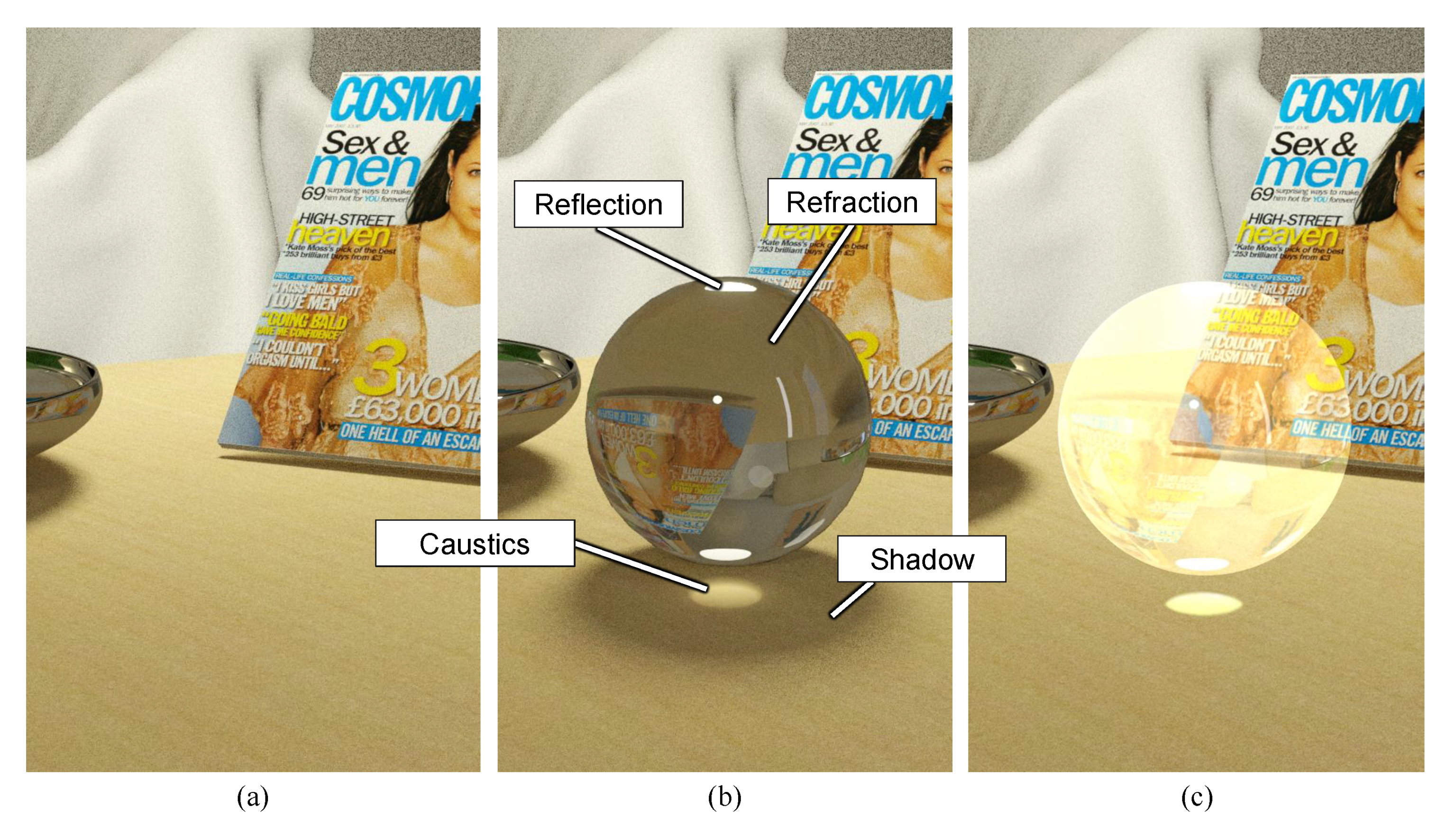
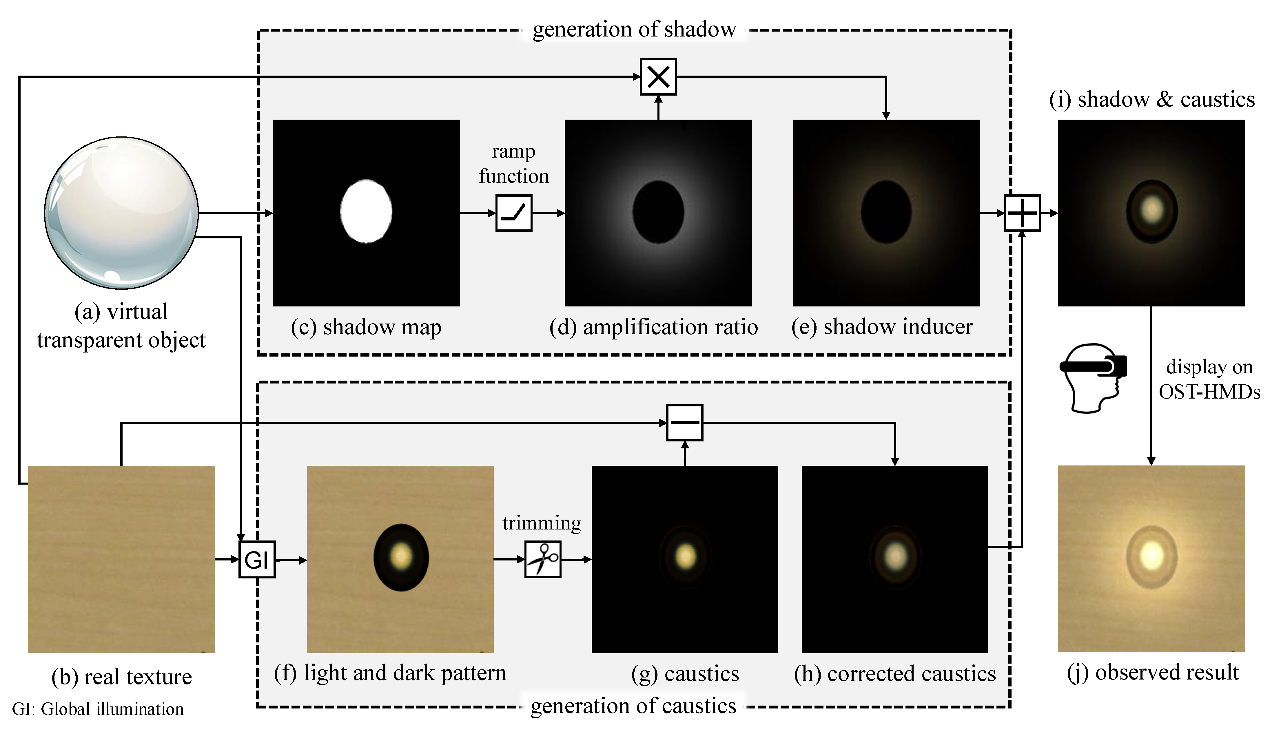
The method proposed in this section represents the shadow using illusionary images without reducing the environmental luminance and then adds the caustics calculated by considering of the relationship between the real floor and the shadow. This process for generating shadow and caustics for OST-HMD representation is shown in Figure 2. In the following subsections, we separately describe the methods used to generate shadow and caustics.
3.1. Methods
3.1.1. Generation of Shadow with Illusion
An illusion-based shadow can be represented by increasing the luminance around the area to be shadowed to make the shadow appear darker. To increase the luminance of the environment without inducing visual discomfort, it is necessary to consider the reflection by the real floor surface on which the shadow is cast. The proposed method represents shadows as virtual objects (hereafter, “shadow inducers”) that increase the luminance around the originally cast shadow areas while taking the reflection of the real floor into account. In this case, the light reaching the observer’s eyes is represented as the sum of light produced by the environment and the light produced by the shadow inducer:
The shadow inducer is generated using the following method. First, the shadow area cast by a virtual transparent object (a) is calculated as a shadow map (c) in a conventional manner [24]. Next, this shadow map is used to generate an amplification ratio (d) for calculating the shadow inducer. This amplification ratio is designed to decrease as the shadow fades to make the increased luminance inconspicuous. It is based on the fact that the human visual system is insensitive to gradual changes in the luminance [25]. Specifically, the amplification ratio at a point P is determined by the distance d from P to point Q, which is the closest point on the shadow edge from P, based on the following ramp function:
where D is the distance from Q to the outer end point of the shadow inducer on the extension of the line segment .
To take the reflection of the real floor into account, the shadow inducer (e) is generated using the luminance of the floor texture (b). Specifically, after correcting the amplification ratio to by applying a coefficient k that determine brightness of shadow inducer against the real floor, the shadow inducer is obtained by multiplying by the real floor texture , or the recorded luminance of the real environment, as follows:
In this study, we manually set the 3-D position of the point light source and tuned the coefficient k empirically while examining the rendering results so that the shadow inducer did not become too bright when compared with the surrounding floor.
Equation (1) can therefore be modified as follows:
3.1.2. Generation of Caustics Adapted to the Real World
The representation of caustics requires a large computational load. Therefore, to enable the real-time representation of caustics, the proposed method calculates them in advance. After setting the size and refractive index of the virtual transparent object and placing it under illumination conditions approximately equal to those of the real environment, the light and dark pattern (f) produced on the real floor (b) by the virtual transparent object is calculated using a global illumination approach such as path tracing or photon mapping [26,27]. The caustics (g) are then obtained by trimming components from the light and dark pattern. Caustics (g) that are simply superimposed onto a real floor will be shown with an enhanced luminance relative to the actual caustics; the proposed method corrects the luminance of the superimposed caustics to a value close to that of the actual luminance. Specifically, the corrected caustics’ is taken as the luminance of the caustics, , without the luminance of the real texture, , as follows:
Finally, the corrected caustics (h) are added to the shadow inducer. The results of this process—OST-HMD-generated shadow and caustics superimposed on a real environment—are shown in (j).
3.2. Implementation
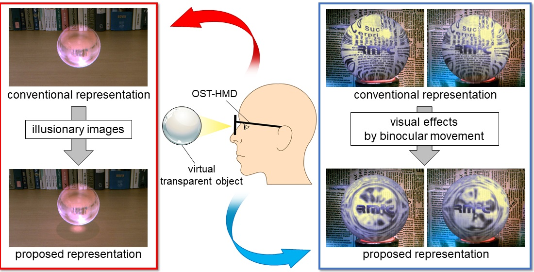
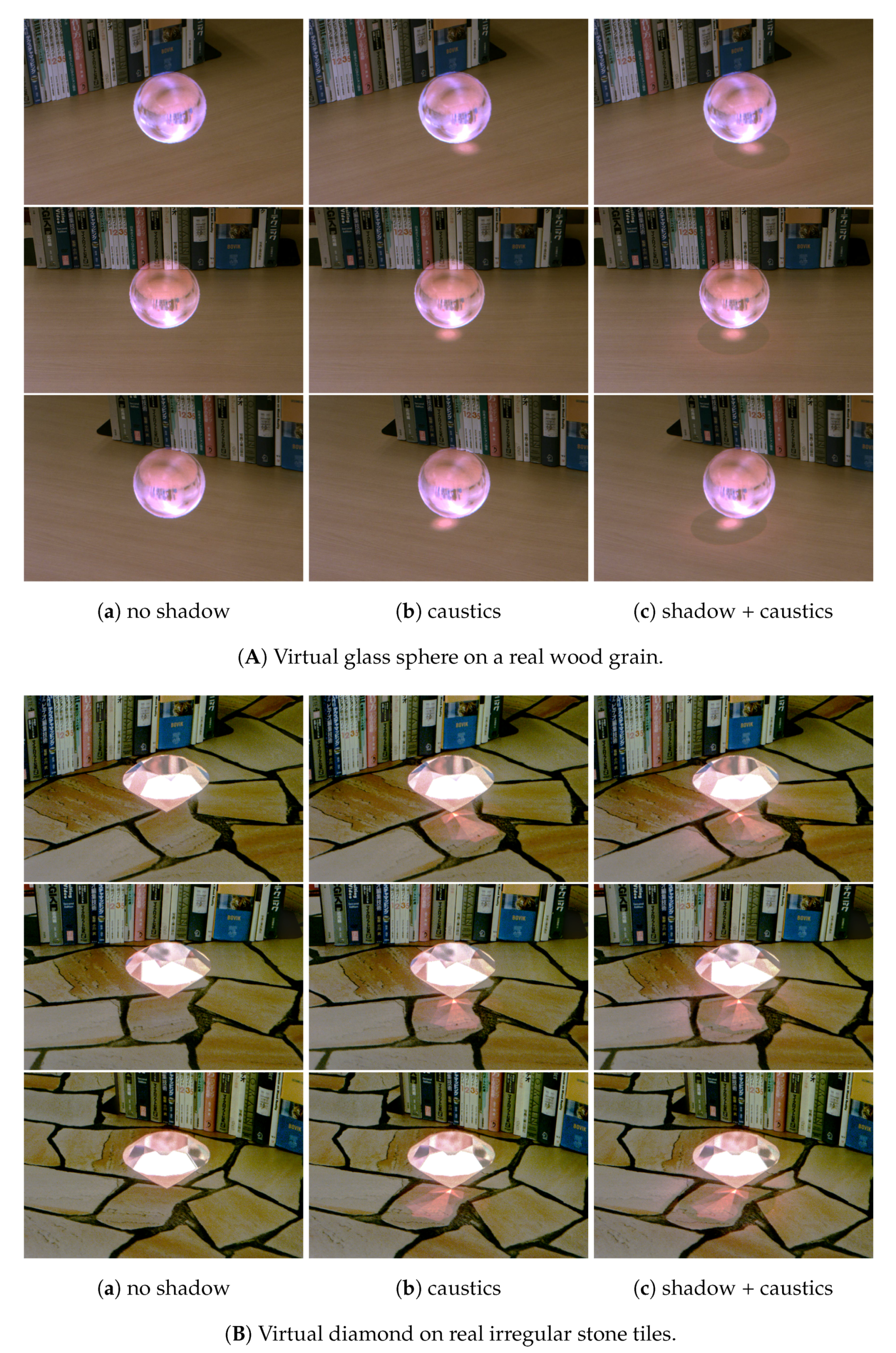
The results of applying the proposed method to represent a glass sphere and a diamond are shown in Figure 3. The image in (a) shows the results of representing only refraction and reflection without shadow or caustics; (b) shows the results of representing the caustics alone, and (c) shows the results of representing both shadow and caustics using the proposed method. The rendering time per image when displayed was more than 18.1ms in every method. In the following, we describe the implementation of our approach in detail. (The results were obtained as multiple exposure images taken through the OST-HMD display. See Appendix A for details.)
3.2.1. Rendering of Virtual Transparent Objects
We used HoloLens smart glasses as the OST-HMD. The observer’s viewpoint was defined as the position/attitude data obtained from the HoloLens sensors. To represent refraction and reflection, the virtual transparent objects were rendered using the Unity renderer (version 2018.2) and shaded using Cg/HLSL. A glass sphere and diamond were represented as virtual transparent objects. Both were dense objects 80 mm in diameter. Based on the refractive index database [28], the refractive indices of the glass sphere and diamond were set to 1.51 and 2.42, respectively. A point light source for illumination was placed in the virtual world of the transparent objects at the local coordinates (0.0, 1.0, 1.0) [m]. The refracted and reflected images were calculated using a real-time representation method [29] in which the environment map was combined with the Fresnel effect. A real-world environment map for reflection and refraction was obtained using an omnidirectional camera (Magicsee P3).
3.2.2. Rendering of Shadow and Caustics
Taking the real-world brightness and FoV of the HoloLens into account, the parameters for generating the shadow inducer were set to and mm. A light and dark pattern comprising shadow and caustics was calculated using the path-tracing method installed in Blender’s Cycles Render (version 2.7). A sampling number for path-tracing of 40 rays per pixel was used, and the resolution of the texture was 1980 × 1980 pixels. The computation time of the rendering was approximately 20 min on a desktop PC using Intel Core i7-7700 CPU (4 cores, 3.60 GHz) with an Nvidia RTX 2070 GPU. The real floor texture was obtained by capturing it in advance using a Canon EOS Kiss X8i DSLR camera instead of the user perspective camera.
4. Evaluation Experiment: Shadow and Caustics
An experiment was carried out to determine whether the shadow and caustics representation produced by the proposed method improves the realism of virtual transparent objects. The experiment comprised two parts. First, a preliminary experiment was carried out to determine how the produced shadow and caustics were perceived by humans. Second, a main experiment was carried out to determine how convincingly the proposed method could represent virtual transparent objects.
4.1. Preliminary Experiment
In the preliminary experiment, we assessed whether the shadow and caustics represented as illusions using the proposed method could be perceived as optical phenomena produced by transparent objects. Moreover, we also investigated the complexity of the shadow and caustic patterns applied to the real floor patterns.
4.1.1. Experimental Environment
In the experiments, the previously described glass sphere and diamond were used as virtual transparent objects. They were rendered using three types of representation: no shadow, with caustics, and with shadow + caustics. Real floor patterns with different complexities—a uniform wood grain pattern and a high-frequency checkered pattern—were prepared. These patterns were given as little reflectivity as possible. The methods for rendering virtual transparent objects and generating the shadow and caustics are described in Section 3.
The HoloLens was used as the OST-HMD in the experiment. The participants were 23 individuals (21 men, 2 women; max. age: 26, min. age: 20, avg.: 22.13, SD: 1.30), all in their twenties and with prior experience of AR using OST-HMDs. Each participant agreed to the purpose of the experiment and all had a corrected visual acuity of 1.0 or greater with no eye abnormalities. In the preliminary experiment, both the shadow and caustics were defined as “shadow” to allow the participants to recognize them as a single optical phenomenon. We showed each participant a picture of a real transparent object and explained to them that both the shadow and caustics were defined as shadow in advance.
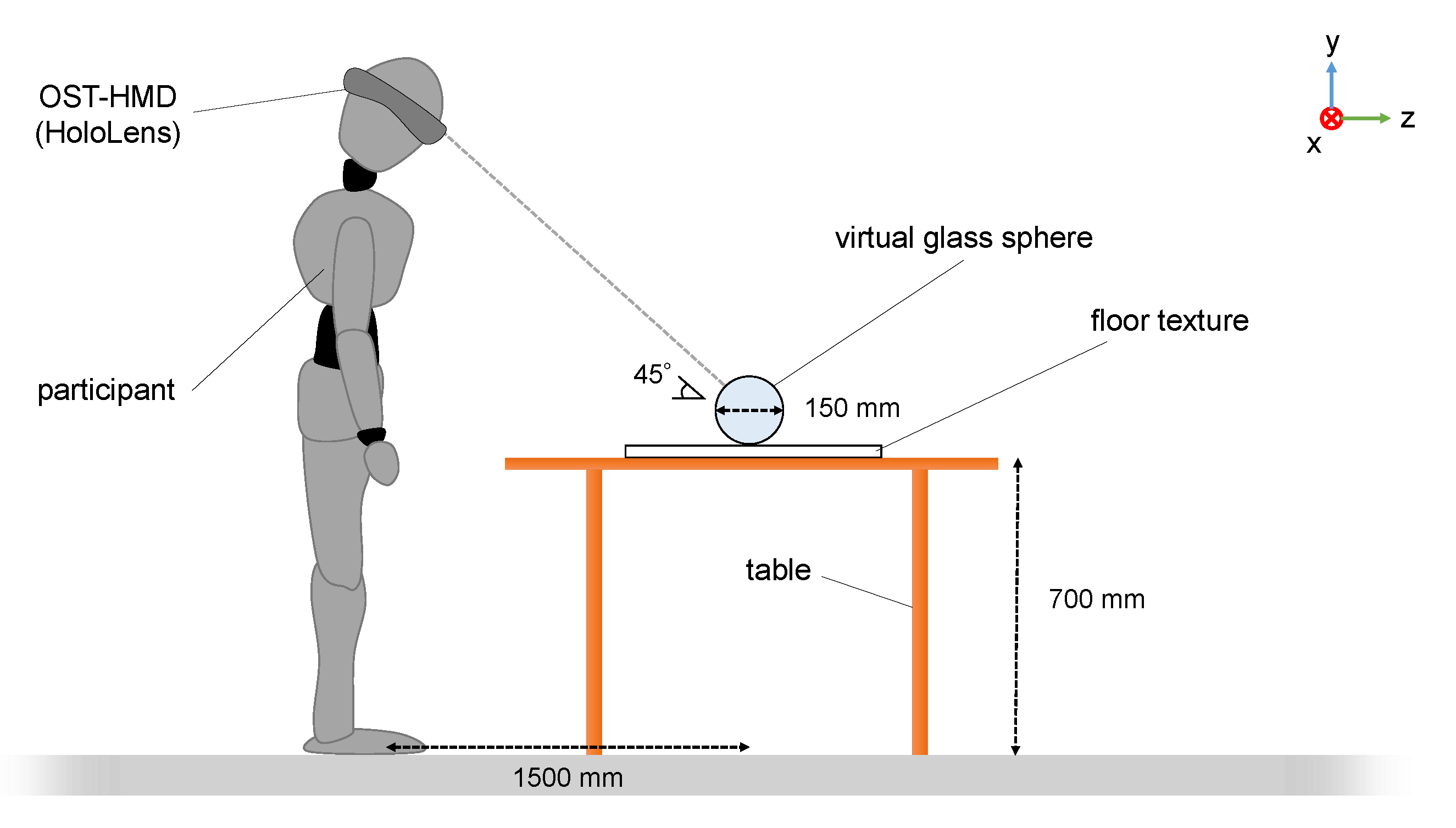
In each experiment, the participant stood approximately 1500 mm away from the visual location of the virtual objects so that the objects appeared in the HMD’s FoV. Each participant observed one of the transparent objects for 1 min while switching between three different representations using the keyboard. While observing, they were allowed to move their head freely within the natural range of motion. Following the observation, they were asked to answer the following questions:
- Q.1
- Which transparent object was most similar to the real one?
- Q.2
- Which transparent object had the shadow most similar to the shadow produced by the real one?
- Q.3
- The shadow of which transparent object had the least amount of light and dark pattern?
Each participant performed a total of four observations—each followed by answering of questions—for different combinations of transparent object and floor patterns. Each set of observation was followed by a 3 min interval. After the experiment, the participants were asked for comments.
4.1.2. Results and Discussion
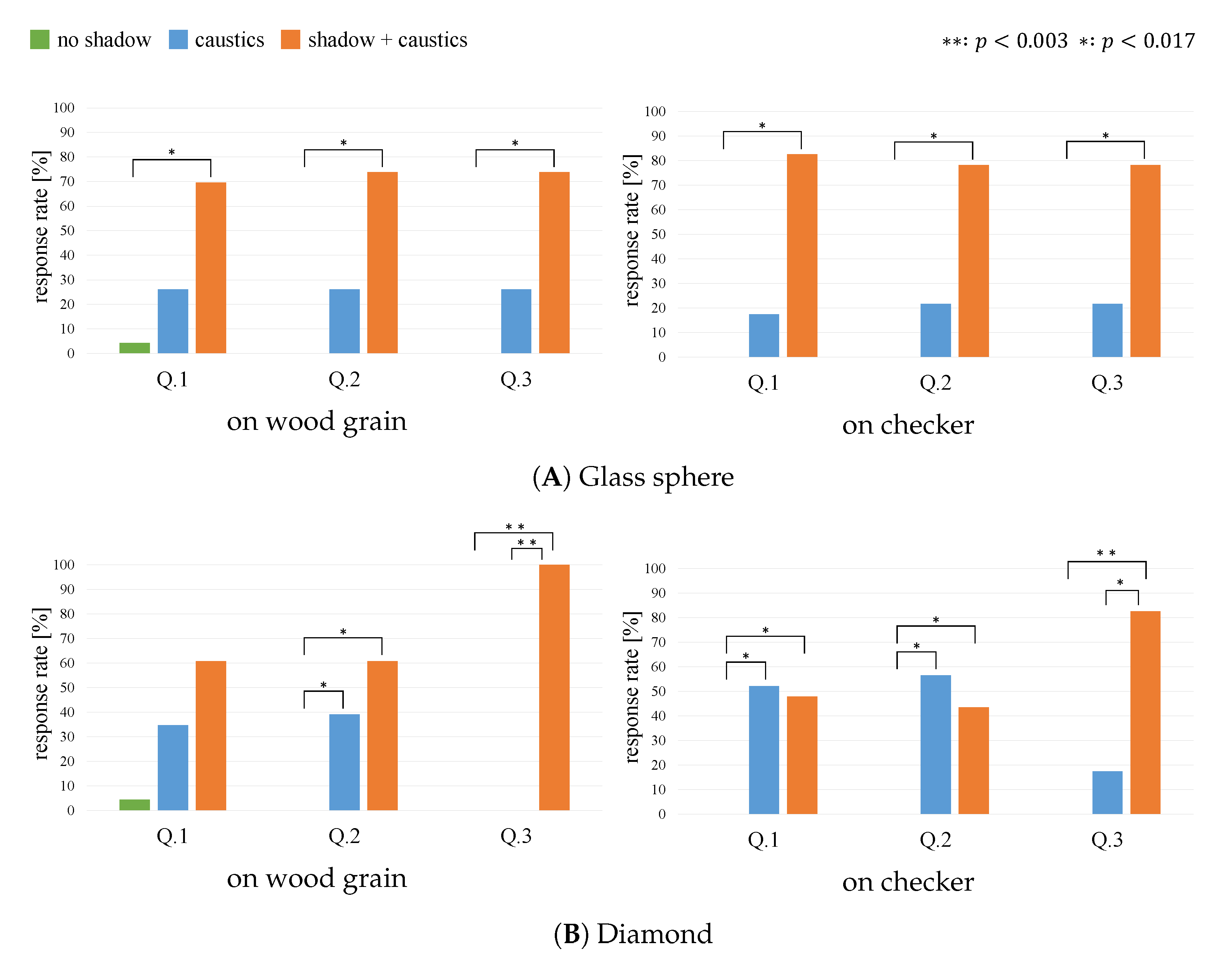
The results of the experiment are shown in Figure 4, in which (A) and (B) show the results for the glass sphere and diamond, respectively. Each comparison result was subjected to a goodness-of-fit test using a p-value () corrected using the Bonferroni method.
The results revealed that “shadow + caustics” had a significantly higher response rate than “no shadow” for all questions, regardless of the floor pattern and the shape of the transparent object. For the checker pattern-and-diamond combination, “caustics” had the highest response rate for questions 1 and 2. Additionally, the proposed method had a higher response rate for most of the questions, although there was no significant difference between “shadow + caustics” and “caustics.”
The experimental results suggest that even pseudo-optical phenomena produced as illusions using the proposed method can be perceived as the shadow and caustics of transparent objects. However, the results also suggest that the magnitude of the effect produced by our method might be dependent on the floor pattern and object shape. Specifically, the effect of the proposed method was greater for wood grains with a uniform pattern and less for checker patterns with a complex pattern. This might be attributable to the fact that the shadow inducer becomes conspicuous due to the misalignment of high-frequency patterns. In terms of virtual transparent object selection, the effect obtained by the glass sphere was greater than that obtained by the diamond. This is consistent with some participants’ comments, in which they stated that they could not perceive the shadow cast by the real diamond. Therefore, the effect of the proposed method might have been diminished in the environment comprising a diamond shape and checkered pattern.
4.2. Main Experiment
The results of the preliminary experiment revealed that, even if the shadow and caustics were represented as illusions using the proposed method, their optical characteristics would be perceived to be quite similar to those produced by an actual transparent object. In the main experiment, we determined whether the proposed method enhances the realism of virtual transparent objects.
4.2.1. Experimental Environment
The virtual transparent objects and floor patterns used in the experiment are shown in Figure 3. A glass sphere and diamond were used as the transparent objects, and wood grain and stone tile patterns were prepared as floor patterns. Three virtual transparent object representations were used: (a) no phenomenon, (b) caustics, and (c) shadow + caustics. Because they had a complex and realistic pattern, stone tiles were chosen as one of the patterns to assess the realism of representing the transparent objects within a real-like environment. As in the preliminary experiment, the real floors were rendered with the reflection reduced as much as possible. The methods used to render virtual transparent objects and generating shadows and caustics are shown in Section 3.
The experimental environment is shown in Figure 5. The HoloLens was again used as the OST-HMD in this experiment. Twenty-three participants, all in their twenties, were involved (21 men, two women). All participants had been involved in the preliminary experiment. The lighting conditions were the same as those of a typical office room. While observing, the participants were allowed to move their head freely within the natural range of motion in a standing posture.
In each experiment, the participant donned the HoloLens; they were given an answer sheet and made to stand approximately 1500 mm from the virtual objects. To inform the participants of the location of each virtual object, a white dummy cube appeared at the same location at which the sphere/diamond would appear. After confirming that the participant were able to perceive the dummy correctly, two pairs of the three representations in (a), (b), and (c) in Figure 3. The stimuli were presented to each participant in a different order to account for the order effect. The following procedure was used to compare each pair of combinations. The first object was displayed for 3.0 s and then removed, 2.0 s, the second object was displayed for 3.0 s. The objects were displayed for 3.0 s to allow the participants’ eyes to adjust to the shadow inducer and enabled them to produce a judgment intuitively without deliberation.
After observing each pair, the participant answered the question “which object looked like a real dense glass sphere/diamond placed on a flat surface?” To indicate which item appeared more convincing, the participant answered either “the former” or “the latter.” From the start of the observation to the answering of each set of questions, each participant performed a total of six sets of observations covering all object/background combinations. Each observation was followed by a 30 s interval that included time to answer the question. After the experiment, we asked the participants for their comments.
4.2.2. Results and Discussion
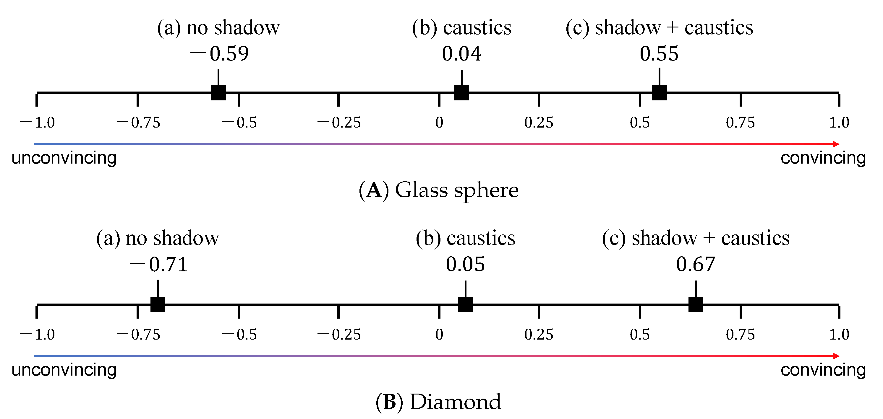
The results of the experiment are shown in Figure 6, in which (A) and (B) indicate the results of the glass sphere and diamond, respectively. We mapped the comparison results to a unified scale using Thurstone’s paired comparison method (Case-V) and performed Mosteller’s test [30] with a significance level of 5%. In the figure, the horizontal axis indicates the extent to which each virtual object appeared to be real on a psychological scale.
The significance of results (A) and (B) were confirmed as ( and (), respectively. The results demonstrated that:
- each virtual transparent object with caustics was more convincing than the same object without shadow effects;
- the virtual objects with shadow and caustics were more convincing than the others.
For the glass sphere, we obtained comments from 16 out of the 23 participants. Thirteen of these comments indicated that the object with both shadow and caustics appeared most convincing. Two of the 16 responses noted that the shadow appeared to be unnaturally bright and did not appear to be the shadow of a transparent object. One noted that the shadow and caustics did not resemble those produced by a transparent object. For the glass sphere, we obtained comments from 18 out of 23 participants. Fourteen of the comments noted that the objects with both shadow and caustics appeared most convincing and that the virtual diamond with both shadow and caustics appeared more convincing of the two. Two respondents noted that the shadow was too conspicuous and did not look like a real shadow. One comment mentioned that the participant did not know how a diamond shadow on the ground should appear. One respondent selected the virtual object without a shadow as the most convincing each time because none of the virtual shadows looked like shadows to the respondent.
These results confirm that the shadow and caustics representations produced by our method have the effect of improving the realism of transparent virtual objects. It is likely that, as we did not intentionally create unconvincing or rarely occurring experimental conditions, the same effects can be achieved in more diverse environments and conditions. Additionally, the results agree with the finding by Kawabe [31] that the presence of shadow and caustics improves the reality of transparent objects. In a demonstration of our system at the IEEE VR 2019 international conference [32], at least 90 out of approximately 130 participants noted that the realism of the system was higher than expected.
On the other hand, in the experiment, some participants commented that did they not experience the intended effect of our method. Although the specific causes of these responses need to be further explored, there are some possible explanations. The most prominent of these is the positional shift of the shadow and caustics. The accuracy of tracking was insufficient, which may have caused the shadow and caustics overlaid onto the floor surface to have shifted in some cases. Here, we used the tracking function of HoloLens. Empirically, registration errors of approximately 1.0 cm frequently occurred. When this type of mis-registration was identified by us or a participant, we reset and adjusted the world coordinate system using keyboard input. However, we cannot ignore the possibility that some participants observed virtual objects without noticing the small misalignments. Overall, our experimental results indicate that the proposed method for representing shadow and caustics has the effect of improving the realism of virtual transparent objects displayed on OST-HMDs. Further investigation will be necessary to determine the effective range and conditions of our approach.
5. Representation of Visual Effects
In this section, we propose a method for reproducing the visual effects of transparent objects that cannot be displayed with optically correct depths on OST-HMDs and discuss the results of its implementation. A real transparent object will comprise multiple images—a surface image, a refracted image, and a reflected image. Each of these will have a different depth, and the visual effects of vergence and accommodation occurring in each will affect the resulting optical image. However, conventional OST-HMDs cannot accurately reproduce the disparities among these images because of computational cost, and cannot reproduce defocus because of the accommodation point will be fixed on the display.
In the method proposed in this section, the visual effects are pseudo reproduced as image of transparent objects. Specifically, disparity is reproduced by calculating the refractive direction corresponding to each eye for each polygon, and defocus is reproduced by blur processing each image with the user’s gaze image taken into account.
5.1. Methods
5.1.1. Reproduction of Disparity in Terms of Vergence
In conventional methods, the disparities among the images of a transparent object can be accurately reproduced by rendering the image for each eye using a ray-tracing method. However, this approach makes it difficult to represent virtual items in real time because of the significant amount of computation required. On the other hand, the proposed method represents transparent objects in real time using a polygon-based calculation. Using this approach, it is possible to reproduce the disparities among images in real time; however, the resulting images are pseudo-images.
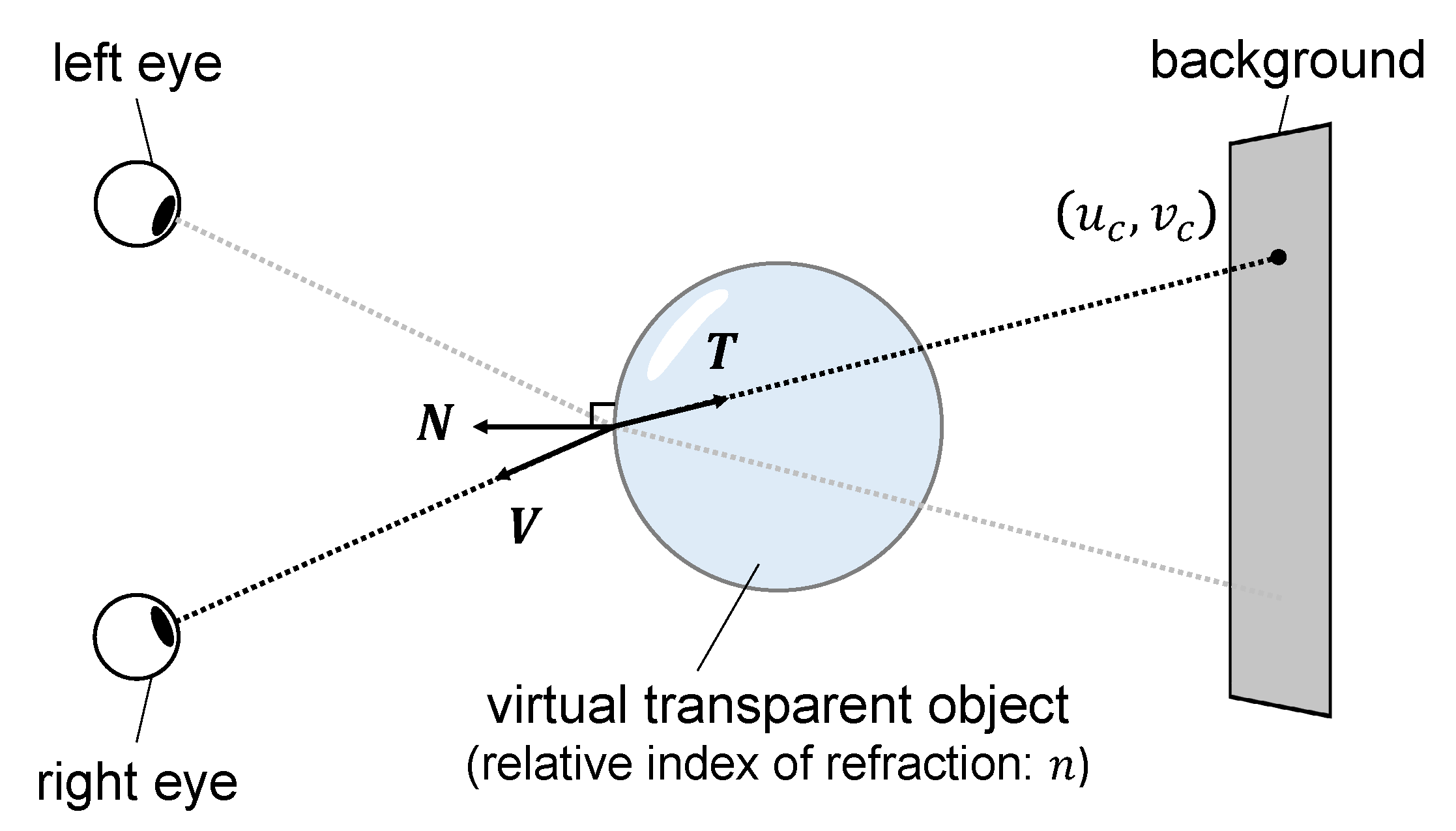
The model for calculating disparity is shown in Figure 7. In this approach, a refractive direction vector is calculated using the polygon normal vector , viewpoint direction vector , and relative refractive index n of the object as follows:
where k is a coefficient expressing the degree of refraction, which can be derived from Snell’s law as follows:
This process is used to compute the refractive direction vectors for each camera. The intersection points with the real-world background texture are sampled to reproduce the disparities among the images. To ensure real-time representation, secondary refraction is not considered, as it can be assumed that human visual processing does not capture image refraction to this extent.
5.1.2. Reproduction of the Defocus in Terms of Accommodation
To reproduce the defocus of each image, the amount of blur is determined based on the distance between the gaze image and other images. To take the defocus caused by eye accommodation into account, the eyeball optics model proposed by Navarro et al. [33] is applied.
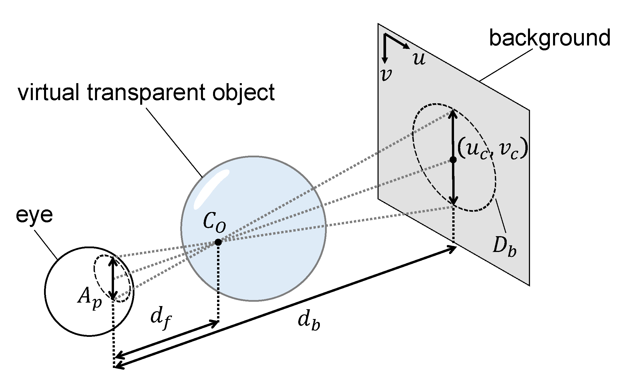
The model for calculating defocus is shown in Figure 8. For a transparent object with a surface color of and a blurred refracted image surface color of , the color output to the OST-HMD, , can be obtained through simple alpha blending as follows:
where is the ratio of the alpha blend. For an observer gazing at the surface of the transparent object, as shown in Figure 8, is calculated using a background texture and a convolutional operation of a point spread function approximated by a 2-D Gaussian function to reproduce the blur on the retina as follows:
where is the variance of the Gaussian function, which is defined as half the kernel size as follows:
As the sampling point obtained by refraction is centered, the range of is defined as follows:
For a real background texture with pixels, an actual length of , and a circular area diameter of , the kernel size is defined as
For a pupil diameter of , can be calculated using similar triangles as
where and are the distances from the eye to the background and focus, respectively. By applying this process to each eye, the disparities among the respective images can be reproduced.
5.2. Implementation
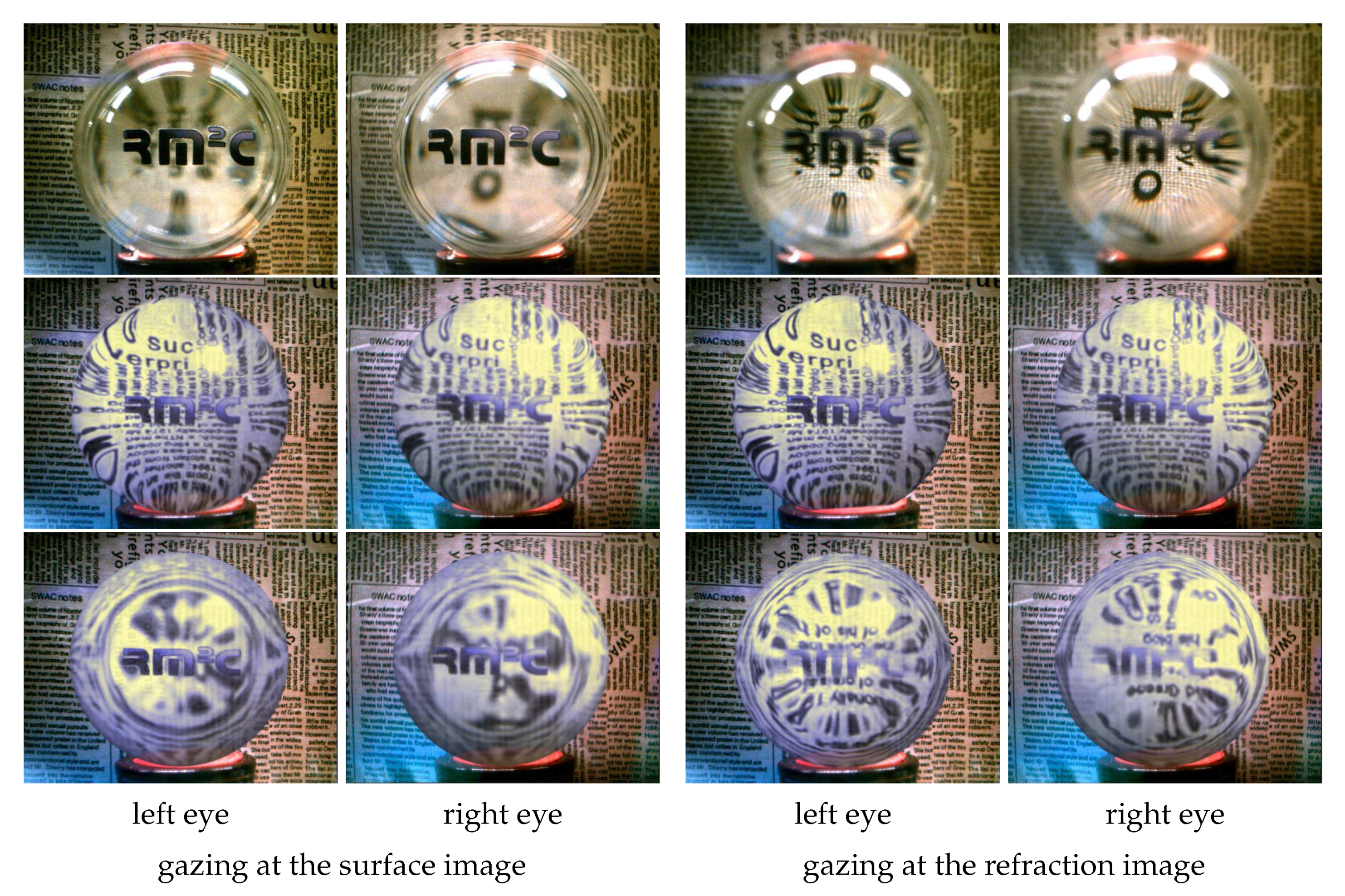
The results of applying several approaches, including our method, to reproduce transparent objects are shown in Figure 9. The upper, middle, and lower rows show a real transparent object, the result produced by a conventional method, and the result produced using the proposed method, respectively. (The virtual transparent objects (middle and bottom rows) were obtained by exposing fused images taken through the display of OST-HMDs. See Appendix A for details.)
The real transparent object was a dense glass sphere with the same size and refractive index as the virtual transparent object and a sticker applied to its surface to reproduce the pattern on the virtual object. The conventionally reproduced virtual transparent object was created using a real-time representation that combined an environment map with the Fresnel effect [29]. The rendering time per image when displayed with the conventional method was approximately 18.1 ms, whereas that with our method was approximately 19.2 ms.
In the results obtained by the real transparent object, there is a disparity between the images produced by the stereo cameras because of their different depths. Additionally, the defocus occurs because of the depth of field of each lens. In the conventional result, the refracted image is represented with the same parallax as the surface image. Additionally, the rendering remains the same regardless of the gaze image. In other words, the conventional method does not reproduce the disparity or defocus. On the other hand, the results obtained using our proposed method ensured that the refracted image patterns are represented differently for each eye. Additionally, when the surface image is viewed it is clearly represented, whereas the refracted image is blurry. Conversely, when the refracted image is viewed, it is clear, whereas the surface image is blurry. In this manner, the proposed method pseudo-reproduces the disparity and defocus. In the following, we describe the implementation of this rendering in detail.
5.2.1. Rendering of Virtual Transparent Objects
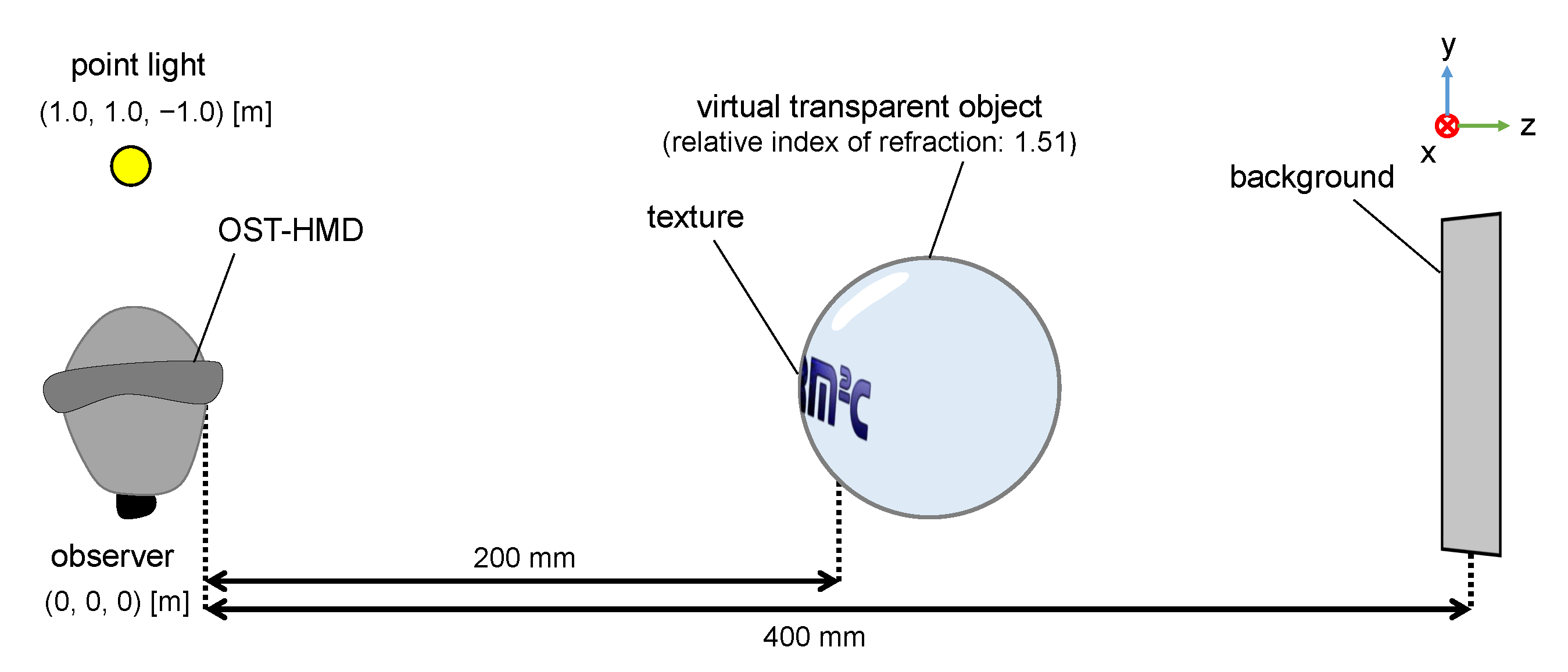
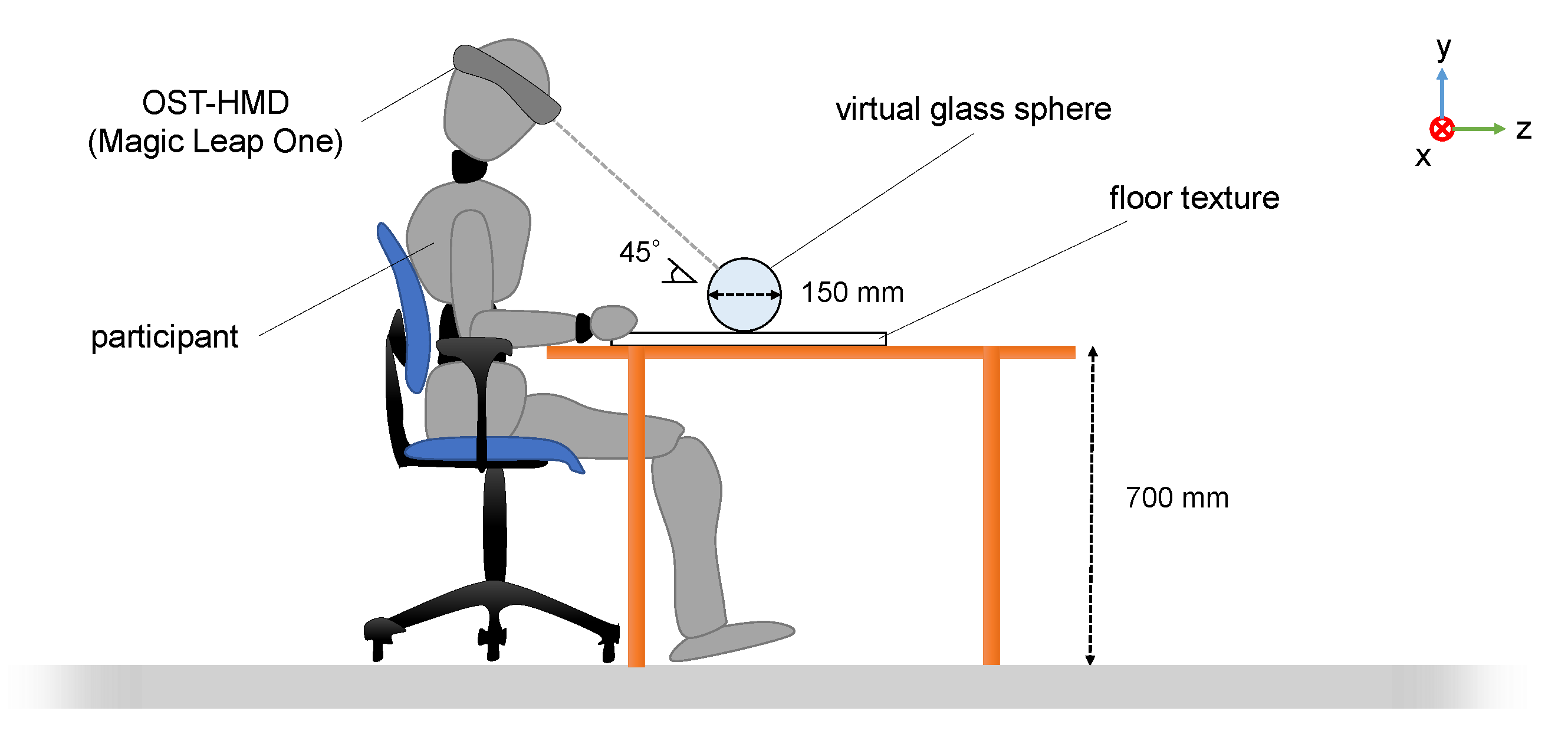
We used Magic Leap One as an OST-HMD. The observer’s viewpoint was defined using position/attitude data obtained from the Magic Leap One sensors. To represent refraction and reflection, the virtual transparent objects were rendered using the Unity renderer and shaded using Cg/HLSL. The constructed environment is shown in Figure 10. A representation of a dense glass sphere with a diameter of 150 mm and refractive index of 1.51 was used as a virtual transparent object. As a gaze cue, its surface was mapped to a texture with a transmittance of 0.8. A virtual point light source was placed in the object’s virtual world at local coordinates (1.0, 1.0, −1.0) [m] relative to the observer. The background texture with a pattern containing high-frequency patterns to facilitate the perception of visual effects was placed at the local coordinates (0.0, 0.0, 0.4) [m] of the observer. The background texture was obtained by capturing a real environment using a DSLR camera (Canon EOS 5D Mark III). To handle the surface and refracted images, which are easily perceived as visual effects, the reflected image was represented using Phong’s model.
5.2.2. Determining the Gaze Image
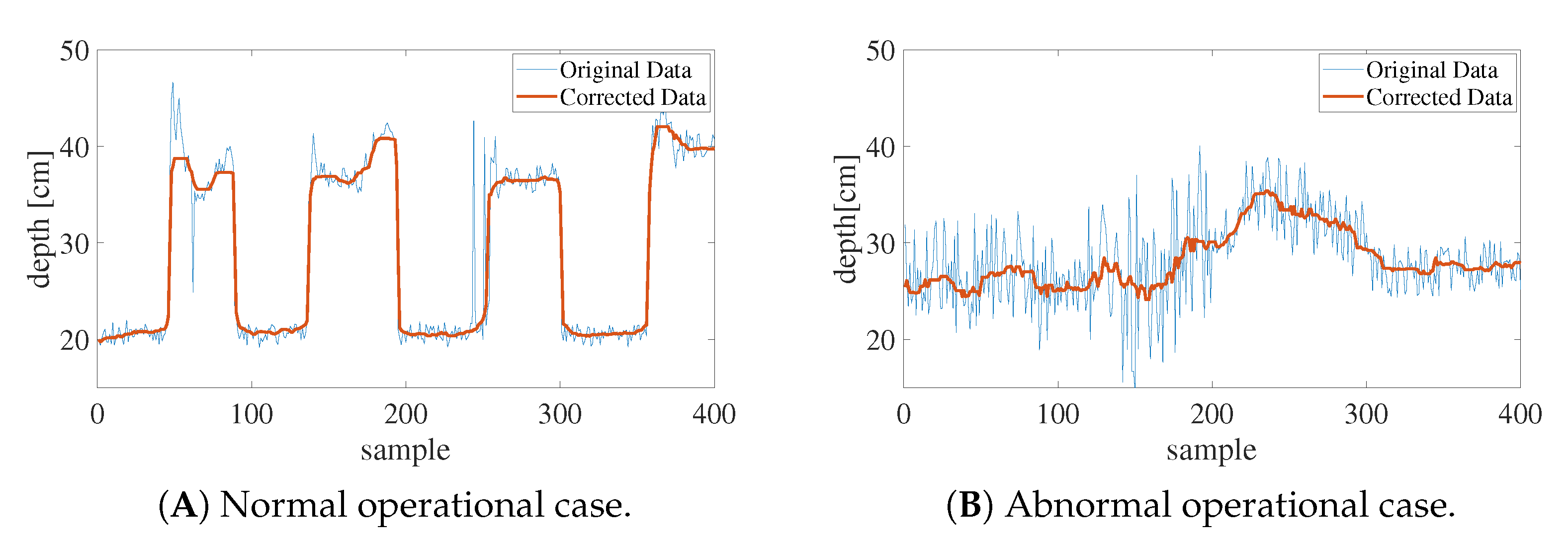
To determine the gaze image, we used the Magic Leap One visual-line detector. It applies an active system comprising an infrared camera and LED that is capable of gathering a user’s gaze data from each eye at 30 Hz. The fixation point was obtained by calculating the intersection of the pre-calibrated user visual lines. However, the results had some noise owing to the accuracy of the detector and the blinking of the eyes. Noise often leads to unintentional visual effects, the depth data of the fixation point were corrected by applying a low-pass filter via a moving average method. The corrected depth data were obtained by extracting 20 currently acquired depth data points from 19 previous points as follows:
Figure 11 shows the depth data results obtained by the observer alternately gazing at the surface and refracted images. It is seen from (A) that the depth data are correctly acquired from the respective images viewed by the user. Furthermore, it was observed that the corrected data reduced the noise relative to the uncorrected data. However, as shown in (B), this approach did not work properly for some users, possibly as a result of differences in the sizes of the users’ eyes or the shadow produced by the eyelids. For this reason, we conducted the experiment without the use of a visual-line detector.
Because of the difficulty in measuring the pupil in real time, each user’s pupil diameter was assumed to be 6.0 mm based on the assumption that the pupil diameter increases in dark settings such as our experimental environment and the range of human pupil diameter change is approximately 2.0 to 8.0 mm [34].
6. Evaluation Experiment: Visual Effects
The purpose of this experiment was to confirm whether the visual effects produced by the proposed method help improve the realism of virtual transparent objects. Since our visual effects are pseudo-reproduced instead of physically reproduced, it was necessary to confirm the extent to which they contribute to improve realism in comparison with real effects. Therefore, we compared the realism of renderings obtained under three representation conditions: a real object, a conventional method representation, and our proposed method representation.
6.1. Experimental Environment
The virtual transparent objects used in the experiment are shown in Figure 9. In addition, we prepared a transparent object that has either disparity or defocus to confirm the effect of each separately. They were constructed using five types of visual effects: —real object; —no effect; —defocus; —disparity; and —disparity and defocus. The methods used to render the virtual transparent objects and reproduce disparity and defocus are presented in Section 5. The diameter of the observer’s pupil was set to 6.0 mm, and no visual-line detector was used because of the individual differences in accuracy that were observed in the preliminary experiments.
The experimental environment is shown in Figure 12, wherein the Magic Leap One was used as the OST-HMD. The floor patterns placed beneath the transparent objects were the same as the background patterns used in Section 5. The real glass sphere had a diameter of 150 mm and a refractive index of 1.51 and had a sticker on its surface that duplicated the virtual sphere surface. To provide a light source, a light (ARRI HMI 575W G22) was placed at the local coordinates (1.0, 1.0, −1.0) [m] relative to the transparent objects in a room with no other light sources.
Twenty-one participants (21 men, 2 women; max. age: 26, min. age: 20, avg.: 22.21, SD: 1.56), all in their twenties and having a corrected visual acuity of 1.0 or greater with no eye abnormalities, were involved in the experiment. All had prior experience of AR using OST-HMDs. Before beginning the experiment, each participant was equipped with the Magic Leap One and given an answer sheet. Then, the participants were made aware of the location at which each virtual object would appear by showing them a white dummy cube. After confirming that the participants could perceive the position correctly, two pairs () of five representations were shown. The stimuli were presented to each participant in a different order to account for the order effect. While observing, the participants were allowed to move only their head freely within the natural range of motion of the sitting posture.
The following procedures were used to observe and then to compare the observational results. Upon the appearance of the first object, each participant observed it for a total of 20 s by alternately gazing at the surface and refracted images under experimenter instructions. Following this, no image was displayed for 10 s, and then the second virtual transparent object was displayed in a similar manner for 20 s. The visual effects were switched as the experimenter provided instructions.
After observing, each participant rated the respective objects, and , in terms of how convincing they appeared to be. A scale from −3 to +3 (−3: very low, −2: low, −1: somewhat low, 0: same, +1: somewhat high, +2: high, +3: very high) was used. Each participant performed a total of 20 sets of observations—each encompassing object observation and question answering—for all combinations. Each set was followed by a 30 s interval that included the answering time. After each experiment, we asked the participants for their comments.
6.2. Results and Discussion
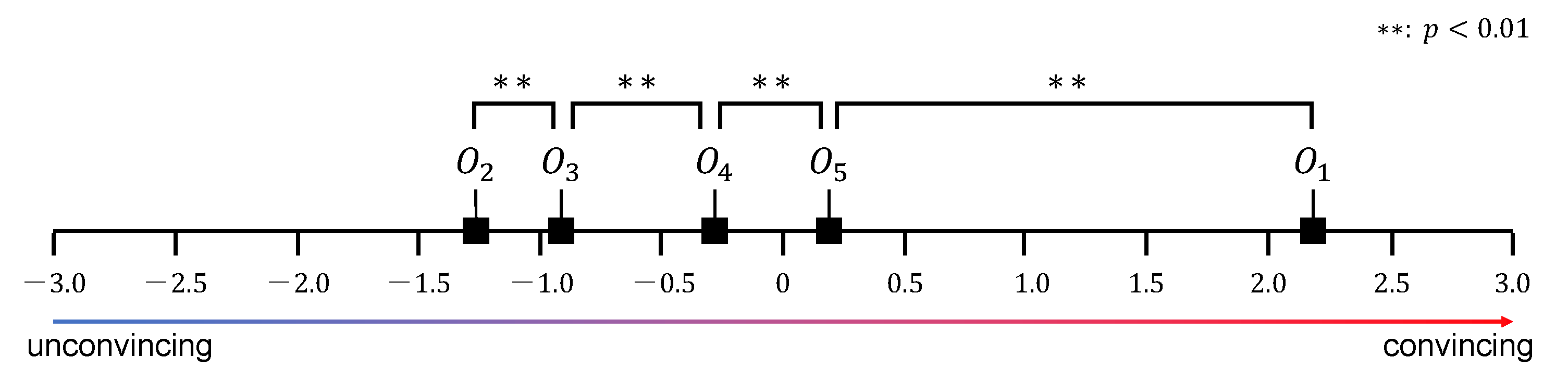
The results of the experiment are shown in Figure 13. We mapped the comparison results to a unified scale using Scheffe’s paired comparison method and performed Turkey’s test. In the figure, the horizontal axis indicates a psychological scale of the extent to which the transparent virtual object appeared to be real. The yardsticks are . The following preference differential significance results were obtained for the respective pairs of transparent objects: ( , , , ). Thus, the objects were found convincing in the following descending order: , , , , and . This in turn suggests that
- a virtual transparent object with either disparity or defocus will be more convincing than one without either visual effect;
- disparity contributes more than defocus to improving the realism of a virtual transparent object;
- a virtual transparent object with both disparity and defocus will be more convincing than one with any other combination of characteristics; and
- even if the proposed method is applied, the realism of a virtual transparent object will not closely approach that of the corresponding real object.
We obtained comments from all participants. Nineteen participants agreed that the transparent object with both disparity and defocus appeared to be the most convinsing. Two answered that the effects of switching objects were visually uncomfortable. One answered that the pseudo-visual effect appeared to differ slightly from the actual visual effect. One answered that they provided one response without evidence because of an inability to perceive any difference.
These results confirm that the visual effects obtained using the proposed method improve the realism of virtual transparent objects. Additionally, the observation that disparity is more effective than defocus is in accordance with the research of Chen et al. [21], which reports that disparity in terms of vergence is most effective in representing transparent objects convincingly.
As noted above, there were some comments indicating that the effects applied by our method are not visually comfortable. Although the specific causes of these comments need to be further explored, there are some possible explanations. First, when users changed focus from one gaze image to another, the switching effect was conspicuous. In the experiments, the gaze image was determined by the experimenter because the participant visual-line detector was insufficiently accurate. This caused unnatural delays in the display of the visual effects that could have induced participant discomfort. Second, the patterns and parallaxes of the refracted images were not accurate. To ensure real-time performance, our method renders only the first refraction based on the assumption that human vision does not accurately recognize the exact pattern of a refracted image. To the best of our knowledge, the actual effect of refracted image accuracy for the realism of rendered transparent objects has not been investigated, and therefore we cannot discard the possibility that some participants felt discomfort with the accuracy of the refracted images. Nevertheless, we can conclude that the use of the proposed method to reproduce visual effects improves the realism of virtual transparent objects despite the inability of the OST-HMD to display at optically correct depths. Further investigation will be necessary to determine the effective range and conditions of our approach.
7. Limitations
In this paper, we proposed two methods for representing transparent objects convincingly and confirmed their effects. In this section, we describe the limitations of applying these methods.
Pre-computation of caustics: Under our method, the caustics are calculated in advance to avoid the high computational cost of real-time representation. Recently, some research [35] has been conducted on the real-time generation of caustics using generative adversarial networks. It might be possible to represent shadow and caustics in real time by applying such a technique.
Shape of transparent object: Our method for displaying shadow and caustics might not be suitable for representing transparent objects with specific shadow patterns. In particular, it is not suitable for transparent objects with holes, such as donut shapes. This is because the luminance gradients of the shadow inducer will overlap within the hole of the shadow, causing the luminance of the hole to become noticeable. Although the width of the gradient is fixed under our current approach, it might be possible to reduce the conspicuousness of this luminance change by dynamically determining the width of the hole by taking the surrounding regions into account.
Own depth of image: Our method for reproducing visual effects assumes planar images; in reality, there will be situations in which separate images have different depths. This can be reflected by increasing the number of gazing planes to reproduce the appropriate visual effects, although doing so would require a highly accurate visual-line detector.
Use of visual line detectors: Our method for reproducing visual effects is based on the premise that gaze images are determined using a visual-line detector. However, we did not use such a detector in the experiments because the accuracy of the detector varied for each individual participants. For this reason, some participants might have felt uncomfortable with the visual effects. To represent visual effects using our method in a more natural manner to all users, a more accurate visual-line detector will be required.
Accuracy of image: To enable real-time representation, our method for reproducing disparity considers only the first refraction. Therefore, the reproduced patterns and parallax of each image differ from those produced by the corresponding real transparent object. We make this tradeoff based on the assumption that the human visual system does not perceive image patterns in a manner that is sufficiently accurate to detect these differences. However, to the best of our knowledge, the effect of image accuracy on the realism of virtual transparent objects has not yet been examined.
Transmission of real world light: As mentioned in Section 1, one of the factors that decreases the realism of displaying virtual transparent objects using OST-HMDs is the penetration of the virtual object by light from the real environment. In this study, the problems were not considered; however, recently, research [19] has been carried out on reducing the effects of environmental light penetration on optical see-through displays. If such a method could be adapted to our method, it might be possible to reduce the effects of real environment light penetration, making it possible to represent virtual transparent objects even more convincingly.
Capturing Real Environment: Our method is based on the assumption that the real environment can be preliminarily modeled to render user-perspective images or that user-perspective images can be captured by cameras located near the positions of the eyes. However, it is difficult to capture and overlay images in real time with a level of error that will not be noticed by the user. In particular, there is currently no solution to this problem under the following conditions: the real surface is near the shadow and the caustics have a specular reflection property; the real surface has complex shapes that are difficult to represent with polygons; or the environment is real, including its illumination, which changes dynamically. In addition, the method adopted in this paper is limited to the fact that the floor surface on which the shadow is cast is flat. Actually, this method can be applied if the texture of the real world, including the unevenness, can be obtained. A related research has been presented by the authors in IEEE VR 2019 [36].
8. Conclusions
In this paper, we proposed two methods for representing virtual transparent objects convincingly on OST-HMDs and confirmed the effects of both. In our method for representing shadow and caustics, light and dark patterns produced by transparent objects are represented as illusionary images without decreasing the luminance of the environment. In the experiments conducted to assess this approach, most of the participants perceived the pseudo-shadows and caustics produced using our method as optical phenomena produced by transparent objects, confirming that the proposed method improves the realism of virtual transparent objects. In our method for producing visual effects, disparities in terms of vergence and defocus induced by accommodation are reproduced. Disparity was reproduced in real time by calculating each transparent object image using a polygon-based method. Defocus is reproduced by blurring each image based on the user’s gaze image. In the corresponding experiments, in which participants compared virtual transparent objects produced with and without visual effects, the proposed method was shown to improve image realism. It was also demonstrated that disparity is more effective than defocus in achieving realism.
These results suggest that pseudo-representation of the characteristics of transparent objects can be used to render such objects convincingly on OST-HMDs. Our results have the potential to alter the perceptions that convincing rendering is impossible in OST-HMDs without the use of SLMs and that OST-HMDs are only suitable for applications using non-photorealistic virtual objects.
Future work will focus on further improving the realism of virtual object representation. We first plan to conduct research on reducing the effects of environmental light on virtual transparent object rendering and to improve the visibility of such objects. Following this, we plan to conduct research on generating shadow and caustics in real time. We previously studied the real-time generation of shadows [36], and we will seek to develop a real-time caustic generation method that can be applied to shadow generation. By achieving these goals, it will be possible to more consistently represent real objects and their relation to dynamic lighting environments.
Author Contributions
Conceptualization, Y.K.; methodology, Y.K.; software, Y.K.; formal analysis, Y.K.; investigation, Y.K.; resources, Y.K.; data curation, Y.K.; Writing—Original draft preparation, Y.K.; Writing—Review and editing: all authors have read and agreed to the published version of the manuscript; validation, A.K., F.S.; supervision, A.K., F.S.; project administration, F.S.; funding acquisition, F.S. All authors have read and agreed to the published version of the manuscript.
Funding
This work was funded by the Japan Society for the Promotion of Grant-in-Aid for Challenging Research (Exploratory) 19K22882. Some of the experimental equipment was provided by NTT DOCOMO.
Institutional Review Board Statement
Not applicable.
Informed Consent Statement
Informed consent was obtained from all participants involved in the study.
Data Availability Statement
Data is contained within the article.
Acknowledgments
We would like to thank all participants of the experiment, as well as a friend for providing language assistance.
Conflicts of Interest
The authors declare that they have no known competing financial interests or personal relationships that could have appeared to influence the work reported in this paper.
Appendix A. Image Acquisition Method
The images in Figure 3 and Figure 9 were obtained by simultaneously capturing both virtual objects and the real environment using a camera (FLIR Systems L3-U3-120S3C-C) mounted in front of an OST-HMD display. Because the dynamic range of our camera was insufficient to capture augmented scenes in a manner in which humans would actually perceive, some of the images used in the study were synthesis images generated from multiple real images with different exposures taken from the same viewpoint. These multiple images were obtained using neutral-density (ND) filters with different transmittance ratios and converted into single merged images via exposure fusion [37]. Table A1 lists the transmittance ratios of the ND filters used for each scene.

Table A1.
Neutral-density (ND) filters used for image acquisitions.
| Virtual Object | Transmittance Ratios of ND Filter(s) |
|---|---|
| Figure 3A: Glass sphere | 100% (no filter) |
| Figure 3B: Diamond | 100%, 50%, 25%, 12.5% |
| Figure 9: Glass sphere (middle low) | 100%, 50%, 25%, 12.5%, 6.25% |
| Figure 9: Glass sphere (lower low) | 100%, 50%, 25%, 12.5%, 6.25% |
References
- Maimone, A.; Georgiou, A.; Kollin, J.S. Holographic Near-Eye Displays for Virtual and Augmented Reality. ACM Trans. Graph. 2017, 36, 1–16. [Google Scholar] [CrossRef]
- Tadamura, K. Photorealistic Representation Method Considering Optical Characteristics for Computer Graphics; The Graduate School of Engineering, Hiroshima University: Hiroshima, Japan, 2003. [Google Scholar] [CrossRef]
- Franzén, O.; Richter, H.; Stark, L. Accommodation and Vergence Mechanisms in the Visual System; Birkhäuser: Basel, Switzerland, 2000. [Google Scholar] [CrossRef]
- Ikeda, S.; Kimura, Y.; Manabe, S.; Kimura, A.; Shibata, F. Shadow induction on optical see-through head-mounted displays. Comput. Graph. 2020, 91, 141–152. [Google Scholar] [CrossRef]
- Kiyokawa, K.; Kurata, Y.; Ohno, H. An optical see-through display for mutual occlusion with a real-time stereovision system. Comput. Graph. 2001, 25, 765–779. [Google Scholar] [CrossRef]
- Kiyokawa, K.; Billinghurst, M.; Campbell, B.; Woods, E. An Occlusion-Capable Optical See-through Head Mount Display for Supporting Co-Located Collaboration. In Proceedings of the 2nd IEEE/ACM International Symposium on Mixed and Augmented Reality (ISMAR 2003), Tokyo, Japan, 10 October 2003; p. 133. [Google Scholar]
- Itoh, Y.; Hamasaki, T.; Sugimoto, M. Occlusion Leak Compensation for Optical See-Through Displays Using a Single-Layer Transmissive Spatial Light Modulator. IEEE Trans. Vis. Comput. Graph. 2017, 23, 2463–2473. [Google Scholar] [CrossRef] [PubMed]
- Maimone, A.; Fuchs, H. Computational augmented reality eyeglasses. In Proceedings of the 12th IEEE International Symposium on Mixed and Augmented Reality (ISMAR 2013), Adelaide, Australia, 1–4 October 2013; pp. 29–38. [Google Scholar]
- Yamaguchi, Y.; Takaki, Y. See-through Integral Imaging Display with Background Occlusion Capability. Appl. Opt. 2016, 55, A144–A149. [Google Scholar] [CrossRef]
- Wann, J.P.; Rushton, S.; Mon-Williams, M. Natural problems for stereoscopic depth perception in virtual environments. Vis. Res. 1995, 35, 2731–2736. [Google Scholar] [CrossRef] [Green Version]
- Rushton, S.K.; Riddell, P.M. Developing visual systems and exposure to virtual reality and stereo displays: Some concerns and speculations about the demands on accommodation and vergence. Appl. Ergon. 1999, 30, 69–78. [Google Scholar] [CrossRef]
- Hoffman, D.M.; Girshick, A.R.; Akeley, K.; Banks, M.S. Vergence–accommodation conflicts hinder visual performance and cause visual fatigue. J. Vis. 2008, 8, 33. [Google Scholar] [CrossRef]
- Dunn, D.; Tippets, C.; Torell, K.; Kellnhofer, P.; Akşit, K.; Didyk, P.; Myszkowski, K.; Luebke, D.; Fuchs, H. Wide Field Of View Varifocal Near-Eye Display Using See-Through Deformable Membrane Mirrors. IEEE Trans. Vis. Comput. Graph. 2017, 23, 1322–1331. [Google Scholar] [CrossRef]
- Liu, S.; Cheng, D.; Hua, H. An optical see-through head mounted display with addressable focal planes. In Proceedings of the 7th IEEE/ACM International Symposium on Mixed and Augmented Reality (ISMAR 2008), Cambridge, UK, 15–18 September 2008; pp. 33–42. [Google Scholar]
- Akşit, K.; Lopes, W.; Kim, J.; Spjut, J.; Patney, A.; Shirley, P.; Luebke, D.; Cholewiak, S.A.; Srinivasan, P.; Ng, R.; et al. Varifocal Virtuality: A Novel Optical Layout for near-Eye Display. In Proceedings of the ACM SIGGRAPH 2017 Emerging Technologies, Los Angeles, CA, USA, 30 July–3 August 2017. [Google Scholar] [CrossRef] [Green Version]
- Douglas, L. Near-eye Light Field Displays. ACM Trans. Graph. 2013, 32, 1–10. [Google Scholar] [CrossRef]
- Maimone, A.; Lanman, D.; Rathinavel, K.; Keller, K.; Luebke, D.; Fuchs, H. Pinlight Displays: Wide Field of View Augmented Reality Eyeglasses Using Defocused Point Light Sources. ACM Trans. Graph. 2014, 33, 89. [Google Scholar] [CrossRef]
- Huang, F.C.; Chen, K.; Wetzstein, G. The Light Field Stereoscope: Immersive Computer Graphics via Factored near-Eye Light Field Displays with Focus Cues. ACM Trans. Graph. 2015, 34, 60. [Google Scholar] [CrossRef]
- Langlotz, T.; Cook, M.; Regenbrecht, H. Real-Time Radiometric Compensation for Optical See-Through Head-Mounted Displays. IEEE Trans. Vis. Comput. Graph. 2016, 22, 2385–2394. [Google Scholar] [CrossRef] [PubMed]
- Fleming, R.; Jäkel, F.; Maloney, L. Visual Perception of Thick Transparent Materials. Psychol. Sci. 2011, 22, 812–820. [Google Scholar] [CrossRef] [Green Version]
- Chen, J.; Allison, R.S. Shape Perception of Thin Transparent Objects with Stereoscopic Viewing. ACM Trans. Appl. Percept. 2013, 10, 15. [Google Scholar] [CrossRef]
- Kán, P.; Kaufmann, H. Physically-Based Depth of Field in Augmented Reality. In Proceedings of the EUROGRAPHICS 2012, Cagliari, Italy, 13–18 May 2012; pp. 89–92. [Google Scholar] [CrossRef]
- Rompapas, D.C.; Rovira, A.; Ikeda, S.; Plopski, A.; Taketomi, T.; Sandor, C.; Kato, H. EyeAR: Refocusable Augmented Reality Content through Eye Measurements. In Proceedings of the 15th IEEE International Symposium on Mixed and Augmented Reality (ISMAR 2016), Merida, Mexico, 19–23 September 2016; pp. 334–335. [Google Scholar]
- Williams, L. Casting Curved Shadows on Curved Surfaces. SIGGRAPH Comput. Graph. 1978, 12. [Google Scholar] [CrossRef]
- Barton, L.; Anderson, J.W. Image segmentation and lightness perception. Nature 2005, 434, 79–83. [Google Scholar] [CrossRef]
- Kay, T.L.; Kajiya, J.T. Ray Tracing Complex Scenes. SIGGRAPH Comput. Graph. 1986, 20, 269–278. [Google Scholar] [CrossRef]
- Jensen, H.W. Global Illumination Using Photon Maps. In Rendering Techniques ’96; Eurographics; Springer: Vienna, Austria, 1996; pp. 21–30. [Google Scholar]
- Polyanskiy, M.N. Refractive Index Database. Available online: https://refractiveindex.info (accessed on 5 January 2020).
- Fernando, R.; Kilgard, M.J. The Cg Tutorial: The Definitive Guide to Programmable Real-Time Graphics; Addison-Wesley Longman Publishing Co., Inc.: Boston, MA, USA, 2003. [Google Scholar]
- Mosteller, F. Remarks on the method of paired comparisons: III. A test of significance for paired comparisons when equal standard deviations and equal correlations are assumed. Psychometrika 1951, 16, 207–218. [Google Scholar] [CrossRef]
- Kawabe, T. Perceptual Transparency From Cast Shadow. i-Perception 2019, 10. [Google Scholar] [CrossRef]
- Kimura, Y.; Manabe, S.; Ikeda, S.; Kimura, A.; Shibata, F. Can Transparent Virtual Objects Be Represented Realistically on OST-HMDs? In Proceedings of the 2019 IEEE Conference on Virtual Reality and 3D User Interfaces (IEEE VR 2019), Osaka, Japan, 23–27 March 2019; pp. 1327–1328. [Google Scholar]
- Navarro, R.; Santamaría, J.; Bescós, J. Accommodation-dependent model of the human eye with aspherics. J. Opt. Soc. Am. 1985, 2, 1273–1280. [Google Scholar] [CrossRef] [PubMed] [Green Version]
- Yoshitomi, T.; Ito, Y.; Inomata, H. Functional innervation and contractile properties of the human iris sphincter muscle. Exp. Eye Res. 1988, 46. [Google Scholar] [CrossRef]
- Okamoto, T.; Nishiura, Y.; Mashita, T.; Ratsamee, P.; Takemura, H. Real-time Generation of Caustics with cGANs for Transparency Manipulation. Corresp. Hum. Interface 2018, 20, 59–64. [Google Scholar]
- Manabe, S.; Ikeda, S.; Kimura, A.; Shibata, F. Shadow Inducers: Inconspicuous Highlights for Casting Virtual Shadows on OST-HMDs. In Proceedings of the 2019 IEEE Conference on Virtual Reality and 3D User Interfaces (IEEE VR 2019), Osaka, Japan, 23–27 March 2019; pp. 1331–1332. [Google Scholar]
- Mertens, T.; Kautz, J.; Reeth, F.V. Exposure Fusion. In Proceedings of the 15th Pacific Conference on Computer Graphics and Applications (PG 2007), Maui, HI, USA, 29 October–2 November 2007; pp. 382–390. [Google Scholar]
Figure 1.
Results of representing a glass sphere as a virtual transparent object on different displays. (a) Real-world environment. (b) Result obtained using an ordinary display (capable of overwriting the real environment pixel-by-pixel). (c) Result obtained using a transmissive display (capable only of light transmission) such as an optical see-through head-mounted display (OST-HMD).

Figure 2.
Process for generating shadow and caustics.

Figure 3.
Virtual transparent objects represented under different conditions.

Figure 4.
Results of the preliminary experiment.

Figure 5.
Experimental environment.

Figure 6.
Results of the main experiment.

Figure 7.
Model for calculating disparity.

Figure 8.
Model for calculating defocus.

Figure 9.
Visual effects of displayed transparent objects. (Upper row): real object. (Middle row): rendering using conventional method. (Lower row): rendering using our method.
Figure 9.
Visual effects of displayed transparent objects. (Upper row): real object. (Middle row): rendering using conventional method. (Lower row): rendering using our method.

Figure 10.
Environment for determining gaze image.

Figure 11.
Fixation point depth data results.

Figure 12.
Experimental environment.

Figure 13.
Experimental results.

Publisher’s Note: MDPI stays neutral with regard to jurisdictional claims in published maps and institutional affiliations. |
© 2021 by the authors. Licensee MDPI, Basel, Switzerland. This article is an open access article distributed under the terms and conditions of the Creative Commons Attribution (CC BY) license (http://creativecommons.org/licenses/by/4.0/).
Share and Cite
MDPI and ACS Style
Kimura, Y.; Kimura, A.; Shibata, F. Representing Virtual Transparent Objects on Optical See-Through Head-Mounted Displays Based on Human Vision. Appl. Sci. 2021, 11, 495. https://doi.org/10.3390/app11020495
AMA Style
Kimura Y, Kimura A, Shibata F. Representing Virtual Transparent Objects on Optical See-Through Head-Mounted Displays Based on Human Vision. Applied Sciences. 2021; 11(2):495. https://doi.org/10.3390/app11020495
Chicago/Turabian StyleKimura, Yuto, Asako Kimura, and Fumihisa Shibata. 2021. "Representing Virtual Transparent Objects on Optical See-Through Head-Mounted Displays Based on Human Vision" Applied Sciences 11, no. 2: 495. https://doi.org/10.3390/app11020495
Note that from the first issue of 2016, this journal uses article numbers instead of page numbers. See further details here.