A Review of Passive Constant Flow Regulators for Microfluidic Applications


Debiotech SA, 28 Avenue de Sévelin, 1004 Lausanne, Switzerland
Appl. Sci. 2020, 10(24), 8858; https://doi.org/10.3390/app10248858
Submission received: 20 November 2020
/
Revised: 3 December 2020
/
Accepted: 7 December 2020
/
Published: 10 December 2020
(This article belongs to the Special Issue Development of Microfluidic Devices for Medical Applications)
Abstract
:This review gives an overview of passive constant flow regulators dedicated to microfluidic applications. Without external control and energy consumption, these devices deliver a constant flow rate regardless of pressure variations, making them very attractive for various microfluidic applications, including drug delivery, flow chemistry, point-of-care tests, or microdialysis. This technical review examines progress over the last three decades in the development of these flow regulators and focuses on the working principle, fabrication methods, performance, and potential applications.
1. Introduction
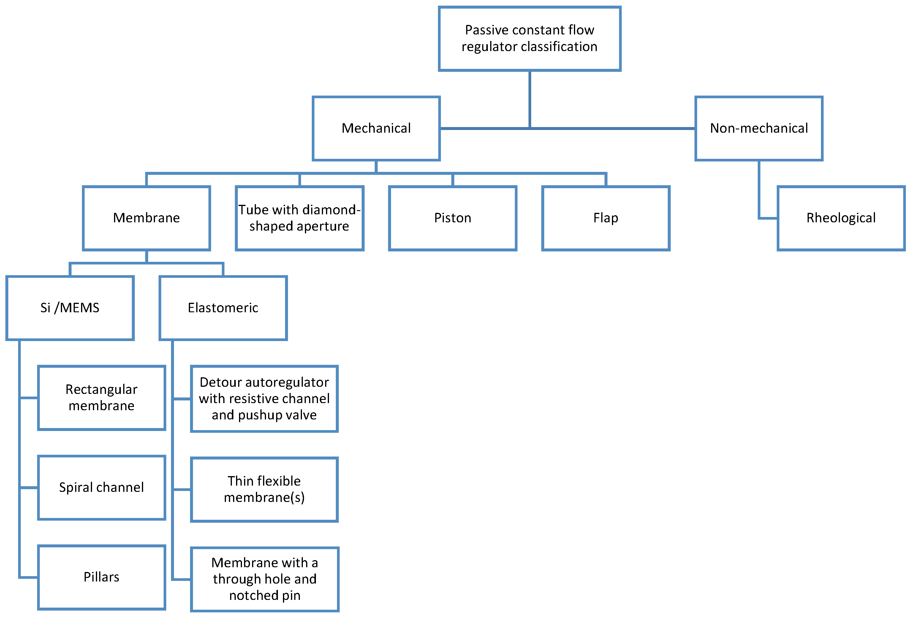
Passive flow control regulators, also known as passive flow control or autoregulated or pressure-compensated valves, deliver a constant flow rate regardless of pressure variations. These valves are widely used in industry for water treatment, process water control (limiting peak flow rate), water authorities (flow limiting, boost mains pressure), centrifugal pump protection, water-saving (domestic showers, drinking fountains), irrigation, etc. [1,2]. These valves are compact, reliable, maintenance-free, and require no energy. Manufacturers (e.g., Maric Flow Control, Tokyo Keiso, Plast-o-Matic, Flowmate, the Lee Corporation, Parker Hannifin, etc.) provide passive valves dedicated to high flow rate (from a few hundred mL/min to 10,000 L/min and more) and large pressure differential (from 1 bar to several hundreds of bar). In this review, a focus is made on passive constant flow valves dedicated to microfluidic applications, including drug delivery, flow chemistry, point-of-care tests, hydrocephalus treatment, microdialysis, etc. These passive flow regulators fall into two main categories: the mechanical regulators having moving parts (a membrane in silicon or elastomer, a piston, a collapsible tubing, or a flap), and non-mechanical regulators without moving parts (fixed geometry), wherein the rheological properties of the fluid are exploited to achieve a constant flow rate. Most of the regulator designs analyzed in this survey belong to the first category. The automatic adjustment of the flow rate with varying pressure conditions is obtained by a change of the fluidic pathway dimensions. A variation of pressure moves a flexible element of the passive flow regulators to induce a change of the fluidic pathway cross-section in almost all configurations except the device with a spiral groove onto a moving piston and the device with a flexible silicon (Si) membrane and a spiral-shaped channel, wherein the length of the channel is automatically adjusted. This classification of the passive constant flow regulators dedicated to microfluidic applications, illustrated in Figure 1, is partly derived from the system set forth by Laser and Santiago for micropumps [3]. The review surveys progress over the last three decades in the development of these passive constant flow regulators. The working principle and performance of each device are discussed, along with a description of the fabrication process and the potential applications.
2. Passive Constant Flow Regulators—General Considerations
2.1. Working Principle
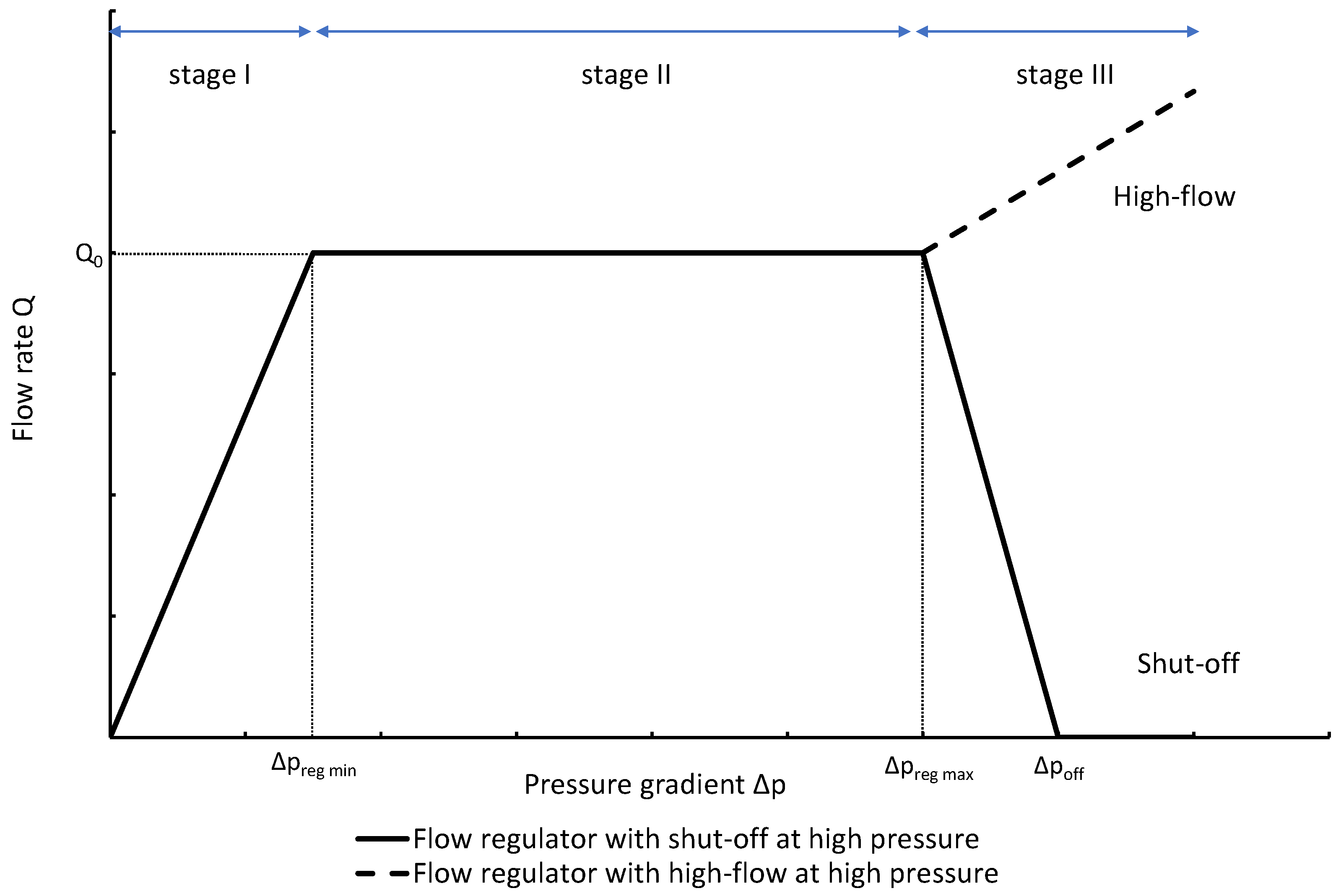
The passive constant flow regulators considered in this review are related to microfluidics, which refers to the manipulation of fluids in channels or structures with dimensions of tens of micrometers [4]. By contrast to macroscopic fluids, viscosity is more important than inertia, and the Reynolds number (Re) that characterizes the ratio of inertial to viscous forces on the fluid is usually lower than 2000 in most microfluidic systems. The flow in such microstructures is in the laminar regime with highly predictable fluid dynamics. The estimation of the hydraulic resistances along the fluid pathway is done using the governing equations of laminar viscous fluid flow (see, e.g., References [5,6]). A constant passive flow regulator is intended to deliver a constant flow rate, in a predefined pressure gradient range comprised between and as illustrated in Figure 2. Further increasing the pressure gradient between the inlet and the outlet can, depending on the regulator design and the target application, either stops the flow rate (passive shut-off feature) or generates a flow rate larger than , the nominal flow rate.
At a given temperature , the flow rate in the flow regulator is:
where is the pressure drop between the inlet and the outlet of the device and is the hydraulic resistance of the device. According to Figure 2, the hydraulic resistance is constant and equal to if . A further increase of the pressure gradient, with induces an increase of the hydraulic resistance, . Using (1), we obtain:
and thus:
To maintain the flow rate constant in the gradient pressure range , the hydraulic resistance of the passive regulator shall linearly increase with the pressure gradient up to , where .
The change of slope in the curve is representative of a nonlinear hydraulic resistor. At higher pressures, the regulator could further increase its hydraulic resistance until the flow is stopped or simply keep the hydraulic resistance constant (see Figure 2). A free-flow at high pressure can be obtained by fully by-passing the nonlinear resistor of the device (possible option for the piston spring valve [7]) or by adding a crack valve in parallel to the flow regulator (option implemented in the CRx Diamond Valve manufactured by Phoenix Biomedical Corp [8]).
The profile shown in Figure 2 is, therefore, representative of a three-stage valve:
- Stage I—low-pressure stage, with low hydraulic resistance for
- Stage II—flow regulation stage, for
- Stage III—high-pressure stage, with a low or high hydraulic resistance for
The passive constant flow regulator is intended to be placed into a fluidic circuit. To keep the functioning point of the device onto the plateau of the characteristic, it is recommended that the device exhibits the largest hydraulic resistance of the circuit.
An alternative method to maintain the flow rate at consists of the control of the pressure at the inlet of a flow restrictor. This method is exploited in constant flow rate implantable pumps for pain management (e.g., Infusaid-400, Medtronic Isomed, Codman 3000, Tricumed IP2000), wherein the reservoir pressure is generated by the vapor pressure of propellant (typically ), or in elastomeric pumps dedicated to ambulatory infusion of medication [6]. In both cases, a fluidic restriction (capillary) is used to set the flow rate in production, but the strategy to maintain the flow rate during the reservoir emptying is different. The propellant vaporizes progressively as the drug is infused toward the patient, while in the second type of device, the elastomeric balloon is designed to keep the pressure almost constant during the treatment. A discussion of the flow rate accuracy of constant implantable pumps is provided by Dumont-fillon et al. [9]. For disposable and other portable infusion pumps, including devices powered by a spring, an elastomeric balloon, a chemical reaction, or a vacuum, overall flow rate accuracy of was reported [10,11,12]. Also, these devices are sensitive to outlet pressure variations and temperature-induced change of the viscosity.
The combination of a pressurized reservoir and a passive constant flow regulator is recommended to avoid startup overflow and the constant decrease of the infusion rate over time as well. The infusion duration is better controlled and a flow rate error less than can be achieved [9].
2.2. Working Fluid
Except for the device developed by Groisman et al. [13], almost all devices considered in this review were designed to work with water, cerebrospinal fluid (CSF), or other Newtonian fluids like viscous mixes of water and glycerol. In principle, the constant passive flow regulators are also compatible with gas. The modeling of a gas flow regulator can still be based on the standard continuum approach, which is still valid if no-slip boundary conditions apply, typically for Knudsen number (viscous flow), where is defined as the ratio of the fluid mean free path and the macroscopic length scale of the physical system [14].
In the laminar regime, a change of temperature induces a change of fluid viscosity which, in turn, leads to flow rate variability as for standard flow restrictors. Since the hydraulic resistance is proportional to the fluid viscosity , the relative flow rate error is thus proportional to the opposite of the relative viscosity change with temperature, considering that the reference temperature is :
Table 1 shows, at selected temperatures, the relative flow rate error due to viscosity change. The values are derived from the empirical formula proposed by Kestin et al. for the dynamic viscosity of water in the range to [15]. Relative flow rate errors vary from to for operating conditions in the range It is noteworthy that additional error sources shall be considered to determine the passive flow regulator accuracy (e.g., fluctuations in the flow regulation stage, hysteresis).
2.3. Materials
Silicon, glass, and poly(dimethylsiloxane) (PDMS) are the most common materials in contact with the working fluid in the passive constant flow regulators reported here. Titanium [7,16] was also considered for implantable devices. Early microfluidic and Micro Total Analysis Systems (µTAS) were made in glass and silicon due to the availability of process equipment and etching recipes. Since the Whitesides’ group manufactured, in 1998, microfluidic devices in PDMS by soft lithography, PDMS became the preferred material for rapid prototyping of microchannel systems for use with biological samples [17,18,19]. Indeed, PDMS is an inexpensive, optically transparent, gas and vapor permeable, hydrophobic, relatively inert, and biocompatible polymer that, moreover, cures at low temperatures. PDMS is soft and facilitates removal from Si molds for micron-scale feature replication. The surface energy of PDMS can be tuned to increase its wettability. Also, PDMS can be sealed reversibly to itself or other materials. Last but not least, the elasticity of PDMS has been widely exploited to create membrane pumps and check valves in active microfluidic devices for cell sorting and biochemical assays [20]. PDMS was also considered to make passive flow regulators because this material enables the rapid prototyping of complex three-dimensional (3D) structures. On the other hand, PDMS presents, compared to Si and glass, some disadvantages that can preterite its use as raw material for specific microfluidic applications that require long-term stability, reproducibility, well-controlled surface chemistry, high accuracy, stiffness, high temperature, compatibility with organic solvents, or low gas/vapor permeability. Si/glass biomedical electromechanical systems (BioMEMS) are more expensive to produce at low volume and require interconnections to the other parts of the fluidic systems. Silicon is a rigid material with a well-defined Young’s modulus by contrast to the hyperelastic PDMS, whose mechanical properties are highly dependent on its degree of cross-linking and stretching. Si membranes exhibit a highly reproducible displacement and no fatigue, and the electronic properties of silicon enable the smart integration of reliable sensors [21]. Also, the negative charge surface of glass and silicon support electroosmotic flow (EOF).
2.4. Modeling
The modeling of the passive constant flow regulator can be based on analytical models [7,22,23], but in a general way, 3D simulations using finite element methods are required to model the fluid–structure interactions (FSI) and the nonlinear behavior of membranes or flaps under large deformations. Numerical simulations are also useful to investigate the impact of machining tolerances on flow rate accuracy [9]. Specific tools using a genetic algorithm have been made to increase the yield in production by design optimization. This method was used to design a regulator with a flexible Si membrane that deflects against pillars. In addition to standard machining tolerances, other non-idealities have been introduced into the model, like wafer misalignment or valve tilt (due to particle contamination for instance) to increase the design robustness [22,24].
A passive flow regulator is usually part of a complex microfluidic system. In addition to these quasi-static analyses of the fluid flow in fixed pressure conditions, further simulations shall be carried out to calculate the fluid dynamics in a system that can include microchannels, check valves, micropumps, pressure sources, etc. As a passive flow regulator induces nonlinear effects, the equations governing the fluidic behavior of such systems generally have no analytical solutions. A classical approach consists of building an electrical equivalent network based on a subdivision of the system into lumped elements and the analogy between fluidic, mechanical, and electrical parameters [25,26]. The impedance of each element is estimated beforehand. For a passive flow regulator with an integrated check-valve, its electrical analog is a diode in series with a variable resistor. The analysis of the dynamics of complex systems can then be carried out very quickly with an electrical simulation tool. This method was chosen to simulate the dynamics of a hydrocephalus shunt comprising a passive flow regulator to divert CSF from the brain ventricles to the peritoneal cavity [27]. The ventricles are equivalent to a constant current source that produces about 20 mL of CSF every hour. The numerical model allowed the determination of the time evolution of intracranial pressure during patient postural changes, changes in the CSF formation rate, oscillations due to the vasogenic system, etc., together with a direct comparison with other shunt designs. Dynamic simulations based on electrical equivalent networks are particularly useful during the design phase to determine the behavior of the passive flow regulator. For a complex system such as the hydrocephalus flow control valve, the model can be further refined by the introduction of experimental data [28].
3. Mechanical Passive Constant Flow Regulators
The main characteristics of the passive constant flow regulators considered in this review are shown in Table A1 in Appendix A. Except for the nonlinear rheological devices made by Groisman et al. [13], all other devices fall into the first category of the classification: mechanical devices with moving parts. The working principle of representative devices of the different subclasses, i.e., devices with Si or elastomeric membranes, a cylinder with a spiral groove, a tube with a lateral aperture, and a flap, is provided with a brief description of their performance and potential applications.
3.1. Devices with Flexible Membrane(s)
3.1.1. Silicon Membrane(s)
Rectangular Si Membrane
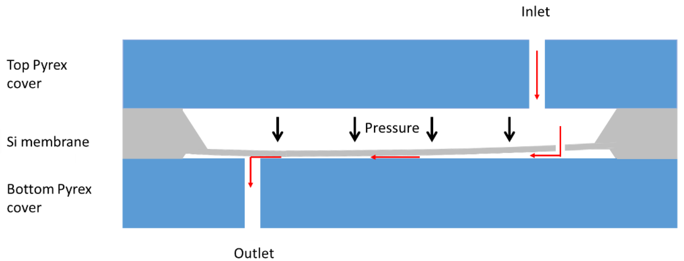
To the best of the author’s knowledge, the first passive constant flow regulator made using microelectromechanical system (MEMS) technology was conceived by Park et al. in 1988 for the treatment of hydrocephalus [29]. The device consists of a silicon wafer (membrane) between the top and bottom Pyrex covers. The rectangular Si membrane deflects, as the pressure increases, toward the bottom Pyrex cover to narrow the fluid path and therefore increase the hydraulic resistance (see Figure 3). Theoretical modeling of the membrane deflection and fluid flow was used to design the passive valve. The thin rectangular membrane was obtained by etching a 2” Si wafer. The top (inlet port) and bottom (outlet port) Pyrex covers were anodically bonded to the middle Si wafer. Tests performed with water showed a constant flow rate of about min in the pressure range for the device with a channel height of , a membrane thickness of and a ratio where and are the channel length and width, respectively. The other design configurations did not show flow saturation. The saturation flow rate and pressure requirements for hydrocephalus (about min in the pressure range mbar) were not met, but the authors used the experimental data to refine the numerical model of this passive flow regulator with a thin rectangular membrane.
Spiral Microchannels
In the device conceived by Park et al. [29], the channel cross-section varies continuously as the pressure changes since the channel is formed by the gap between the bottom of the moving membrane and the bottom cover. Considering also that the flow-induced pressure distribution along the channel leads to non-symmetrical membrane deformation, it must be stressed that the design of a constant flow regulator with such a structure is a challenging engineering task. An alternative passive flow regulator design comprising a well-defined channel cross-section was investigated by Amacker et al. at EPFL in 1998 [16] and further developed by Cousseau et al. at Debiotech SA in 2001 [30]. The device structure, shown in Figure 4, comprises an inlet port, a circular Si membrane with a central hole, a spiraling microchannel etched in a Pyrex substrate, and an outlet port. As the pressure difference between the inlet and the outlet increases, the Si membrane deflects and reduces the gap between the membrane and the substrate. At low pressure, the main hydraulic resistance is due to the hole in the membrane. Once the membrane is in contact with the substrate, the fluid is forced to flow through the microchannel. The contact radius of the membrane with the substrate as a function of the pressure is obtained by finite element method (FEM) simulations since the membrane deflection is highly nonlinear. Constant microchannel cross-sections were considered in the two studies [16,30]. Therefore, constant flow regulation was achieved by calculating a spiral channel in a way that the part of the channel covered by the membrane increases linearly with the pressure. The target water flow rates of these passive devices for implantable drug delivery systems are [16] and [30].
Amacker et al. used a Si membrane with a hole of in diameter obtained by laser ablation. The channel in the glass substrate was etched in a hydrofluoric acid (HF) solution. Finally, the membrane and the substrate were anodically bonded together. An alternative Titanium device was made of a stack of laser-drilled and electrochemically micromachined Ti sheets. A spacer ring was used to form the gap between the membrane and the substrate. The laminated Ti sheets were finally welded together. Water flow regulation at () was demonstrated in the pressure range mbar. At higher pressure, the flow increased beyond the regulation limit [16].
Cousseau et al. used a stack of three wafers: a top Pyrex wafer for fluidic connection, a central Si wafer for the membrane, and a bottom Si wafer for the microchannel substrate [30]. The membrane and the bottom channel are assembled, after structuration, by direct bonding, while the top wafer is anodically bonded to the membrane/substrate stack. After the determination of the contact radius of the membrane with the substrate as a function of the applied pressure, a 3D fluidic model was created and the program TASCflow was used to solve the incompressible Navier-Stokes equations. Three different designs were tested using water with nominal flow rates of , , and . The profile of the design showed, after a flow rate overshoot at low pressure (up to ), a constant water flow rate of in the pressure range mbar. At higher pressure, in the shut-off range mbar, the flow rate decreases progressively. Above the channel is completely covered by the membrane and the flow is blocked. Long-term stability (26 days) and the ability to compensate for a sinusoidal pressure between and were also demonstrated [30].
Pillar Valves in Parallel
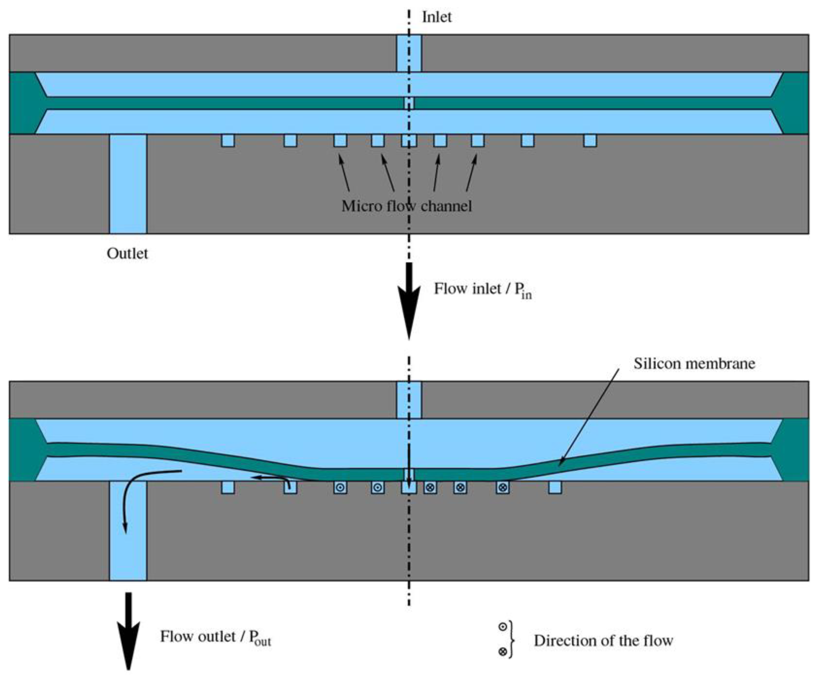
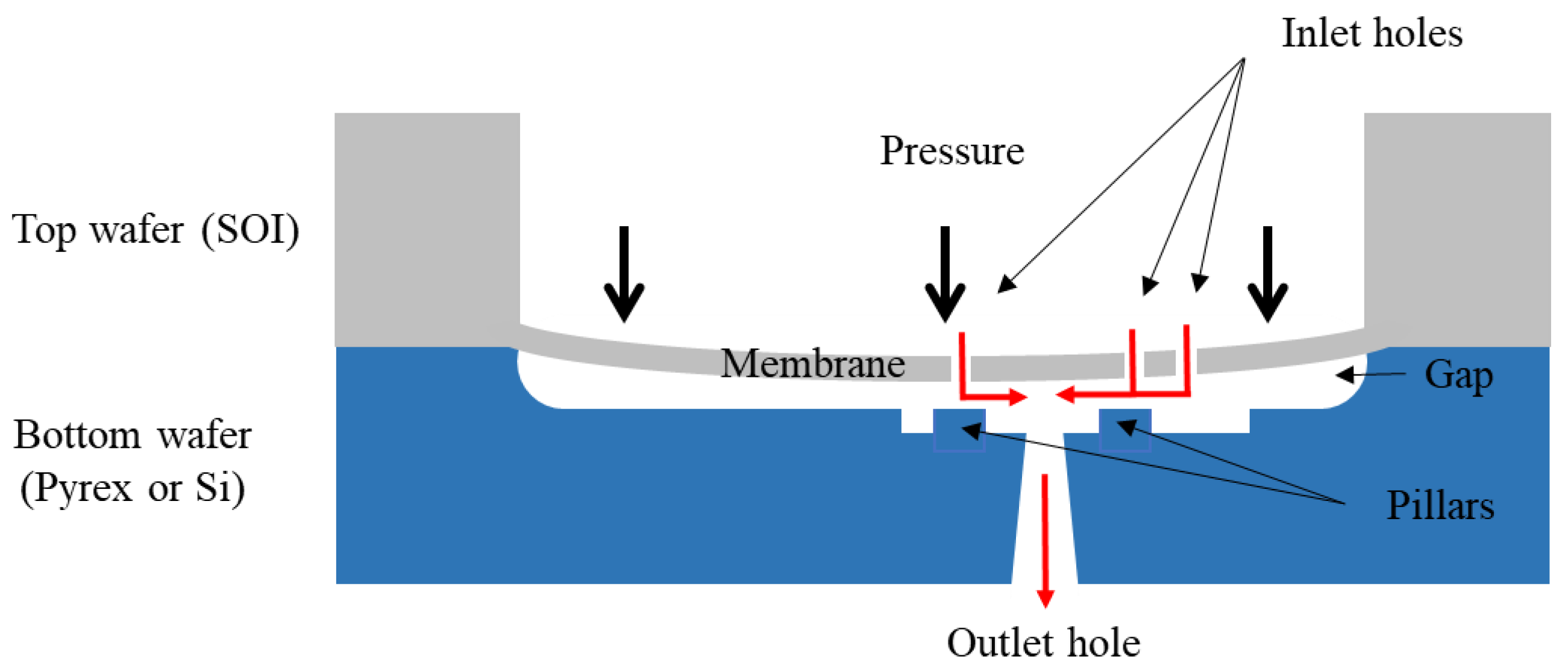
The passive flow regulators with a flexible Si membrane and a spiral microchannel required extended numerical simulations and are by design sensitive to particles, since the contact surface between the membrane and the substrate is large. Moreover, for square or semicircular microchannel cross-sections, flow rate varies as a power 4 with microchannel dimensions and the microchannel machining is a Critical-To-Quality (CTQ) process step due to the absence of etch stop. An alternative design made of a drilled Si membrane and a substrate with pillars, as shown in Figure 5, has been examined to overcome these abovementioned drawbacks [31]. A membrane hole and its facing pillar form a valve that closes progressively as the pressure increases. The resulting reduction of the gap between the top surface of the pillar and the bottom of the Si membrane leads to an increase in the hydrodynamic resistance of this radial valve. The valve modeling requires the determination, using 3D FEM simulations, of the membrane deflection and the fluid flow as a function of the pressure gradient. Simplified analytical models supported by experimental data were also used to simplify the design phase [32]. The total flow rate is the sum of the flows through each valve :
where is the pressure gradient between inlet and outlet and is the hydraulic resistance of the valve . To meet the targeted constant flow rate specification, a dedicated simulation tool based on a genetic algorithm has been developed to limit, by an optimization of the number of valves in parallel, their radial positions, the dimensions of the holes and pillars, etc., the impact of the machining tolerances on flow accuracy [22,24]. This regulator structure has been designed for CSF drainage [33] and drug delivery [22]. At high pressure, if each hole is associated with a facing pillar, all valves are closed and the flow is stopped. For the treatment of hydrocephalus, to prevent CSF accumulation and episodes of high intracranial pressure, the valve shall exhibit, as a safety feature, a low hydraulic resistance at high pressure. For this purpose, the specific regulator design includes a valve consisting of a pillarless hole to allow drainage of CSF at a high flow rate beyond the regulation range [33].
The passive constant flow regulator comprises a substrate made of glass or silicon, wherein the pillars and the outlet hole are machined, either by a combination of wet etch and sandblasting [30] or sequential dry etches [34]. The circular membrane with well-controlled thickness is obtained by dry etch of a silicon on insulator (SOI) wafer. Devices dedicated to low (respectively high) pressure applications have large and thin (respectively small and thick) flexible membranes. The final assembly consists of an anodic bonding of the two wafers (via a thin intermediate borosilicate layer for the Si-Si configuration [34]).
For the device dedicated to hydrocephalus, a constant flow rate of at 20 °C (equivalent to at 37 °C) was measured in the pressure range mbar using water [33]. Cornaggia et al. designed three different devices for the infusion of viscous fluids at high pressure, using thick SOI of , membranes with a diameter of , and a water and glycerol mixture as working fluid [22]. For design A, a constant flow of was measured at (or in the pressure range bar. Designs B and C were tested using a water/glycerol mixture and showed, respectively, a constant flow of in the pressure range bar and in the pressure range bar. Two similar device structures were tested by Conti et al., who reported constant flow rates of respectively in the pressure range bar and in the pressure range bar [34].
Numerical simulations showed that flow rate variability due to the temperature dependence of the fluid viscosity can be mitigated by the use of a polyethylene block glued at room temperature beneath the pillar substrate made flexible by an additional backside etch [35]. This polyethylene (PE) block, which exhibits a large coefficient of thermal expansion of about , is used as a passive thermal actuator that generates a large upward or downward force onto the substrate that respectively reduces or increases the gap between the membrane and the substrate as the temperature varies. A flow regulator delivering a constant water flow rate of at 20 °C has been considered for the simulations. It was shown that the automatic adjustment of the gap due to the presence of the PE block keeps the flow constant at in the temperature range and the pressure range . Such a feature would improve the overall flow rate variability of a passive constant flow regulator used in an ambulatory infusion system.
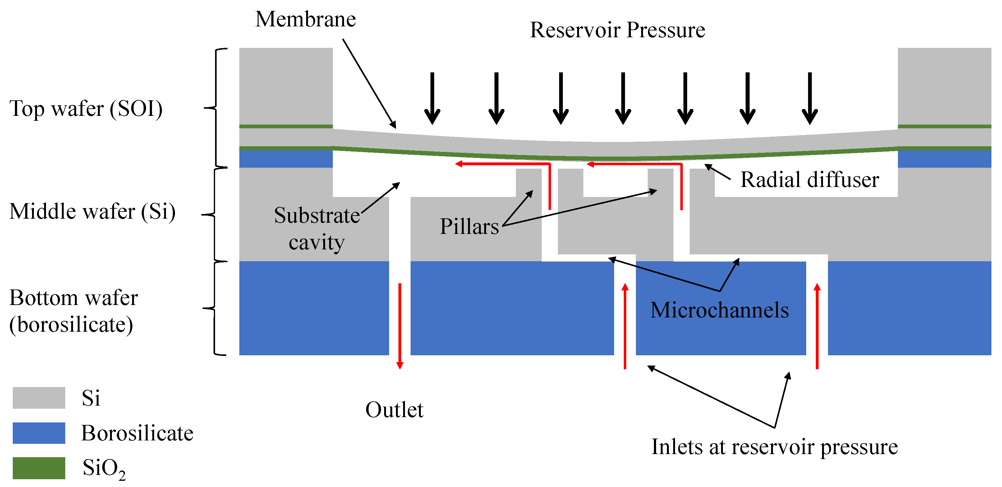
The simulation tools specifically developed for this regulator design showed that for a target constant flow rate lower than at 1 cP, the machining tolerances of the membrane hole diameters significantly narrow and become an important yield detractor in production. Infusion error larger than at could be expected [9]. To achieve a constant flow rate as low as or less, Dumont-fillon et al. designed a triple-stack structure made of an SOI wafer to form a flexible membrane with no holes, a middle Si wafer with pillars, through holes and microchannels, and a bottom borosilicate wafer with inlet and outlet ports (see Figure 6) [9].
Flow regulation is again achieved by the deflection of a silicon membrane which gradually obstructs the fluid path as the pressure increases. The device has several valves in parallel, each valve consisting of an inlet port, a microchannel, a through hole in a pillar, and a radial diffuser (fluidic restriction between the top of the pillar and the bottom membrane). By contrast to the other elements of the valve, the hydraulic resistance of the radial diffusers varies with the pressure. The number of valves and their positions and dimensions are adjusted to meet the targeted fluidic characteristic of the passive constant flow regulator. At low pressure, the main hydraulic resistance is no longer a tiny hole but a long microchannel with a well-controlled cross-section obtained by anisotropic wet etch (potassium hydroxide (KOH)) of (100) Si wafers. A SOI with a buried oxide was used to form the circular membrane (3.5 mm in diameter). A borosilicate thick spacer was deposited to form the gap and to anodically bond the Si membrane wafer to the Si middle wafer. Two different devices dedicated to implantable infusion systems were designed to deliver a constant flow rate of (High Flow (HF) design) and (Low Flow (LF) design), respectively. The samples were manufactured in a clean room and tested using water at 20 °C. The HF and LF samples exhibited a constant flow rate of and respectively, in the pressure range mbar. Replacing the fluidic restriction of a fixed-rate implantable pump by a passive constant flow regulator would enable a reduction in flow variability by up to a factor 2.4, and, for a safer refill procedure, a lowering of the reservoir pressure by a factor 5, from 2.5 to 0.5 bar [5,9].
3.1.2. Devices with Compliant Elastomeric Membrane(s)
In 2005, Yang et al. made early use of compliant PDMS membranes for the dynamic flow stabilization in microfluidic systems [36]. The device consists of a microchannel and PDMS membranes in series on one or more walls of the channel. The compliant membranes are equivalent to capacitors that are used to remove fluctuations in a pulsatile flow, and thus nearly constant outlet flow rates and pressure were obtained. To obtain a regulation of the flow rate at set pressures, other device structures were investigated. The present section of the review provides a detailed description of these passive devices that exploit the compliance of elastomeric membranes to achieve a constant flow rate under varying static pressure conditions.
Detour Autoregulator
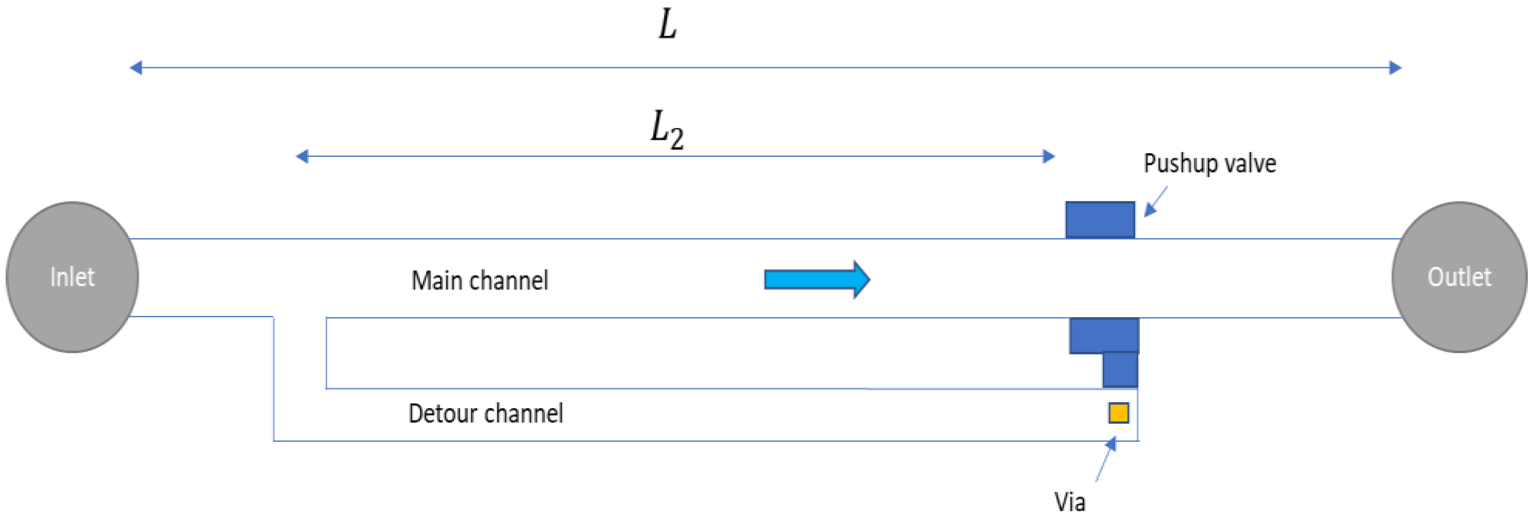
Kartalov’s group developed several detour autoregulatory devices in PDMS [37,38,39]. A schematic description of the working principle of these devices is provided in Figure 7. Pressure on the working fluid is applied at the inlet to produce a flow in the main channel of the upper layer. A detour channel is in fluidic connection with the main channel and through a via with a pushup valve located in the lower layer. The fluid flow induces a decrease of the pressure along the main channel while the static pressure in the detour channel remains constant and equal to the pressure value at the split point of the two channels. The increase of the applied pressure generates a larger pressure drop along the main channel and thus the pushup valve will progressively obstruct the main channel and generate a nonlinear fluidic behavior for Newtonian fluids (see Reference [40] for the characterization of the mechanical behavior of microfluidic valves in PDMS and Reference [41] for the flow-induced deformation of shallow microchannels in PDMS). Chang et al. proposed quantitative modeling of this microfluidic system in PDMS used as a current source [39]. The characteristic shows, at low pressure, a linear behavior with a slope inversely proportional to the hydraulic resistance of the non-deformed main channel. Further increasing the applied pressure gradient induces nonlinearity due to the activation of the pushup valve, and the flow rate remains constant beyond a saturation pressure defined as the point where .
Several microfluidic devices made of a stack of PDMS layers (Dow Corning Sylgard 184) with vertical connections (vias) were fabricated and tested using water. Constant flow rates of , 0.0198, and 0.024 mL/min were measured in the pressure range for detour channel ratio of 0.8, 0.68, and 0.57 respectively, in good agreement with modeling data [37,39]. Liu et al. measured, for a fixed detour channel ratio of 0.66, the effect of the increase of the pushup valve width on saturation pressure and flow rate [38]. For pushup valve width of and , the flow rate did not saturate, and the showed a small and positive slope above . Saturation was obtained for pushup valve width of , and , with saturation flow rate and pressure of in the range in the range , and in the range , respectively. As the valve width increases, the saturated flow rate and pressure decrease, as expected [39,40]. The authors reported that valves having widths of and more would irreversibly stick shut during either fabrication or operation [38]. The saturation point of this passive constant flow regulator for Newtonian fluids can thus be tuned by adjusting the detour channel ratio and the valve dimensions. These 3D structures in PDMS enable the miniaturization of autoregulatory devices for biochemical and biomedical applications.
Flow Regulator with Passive Membrane Valve in PDMS
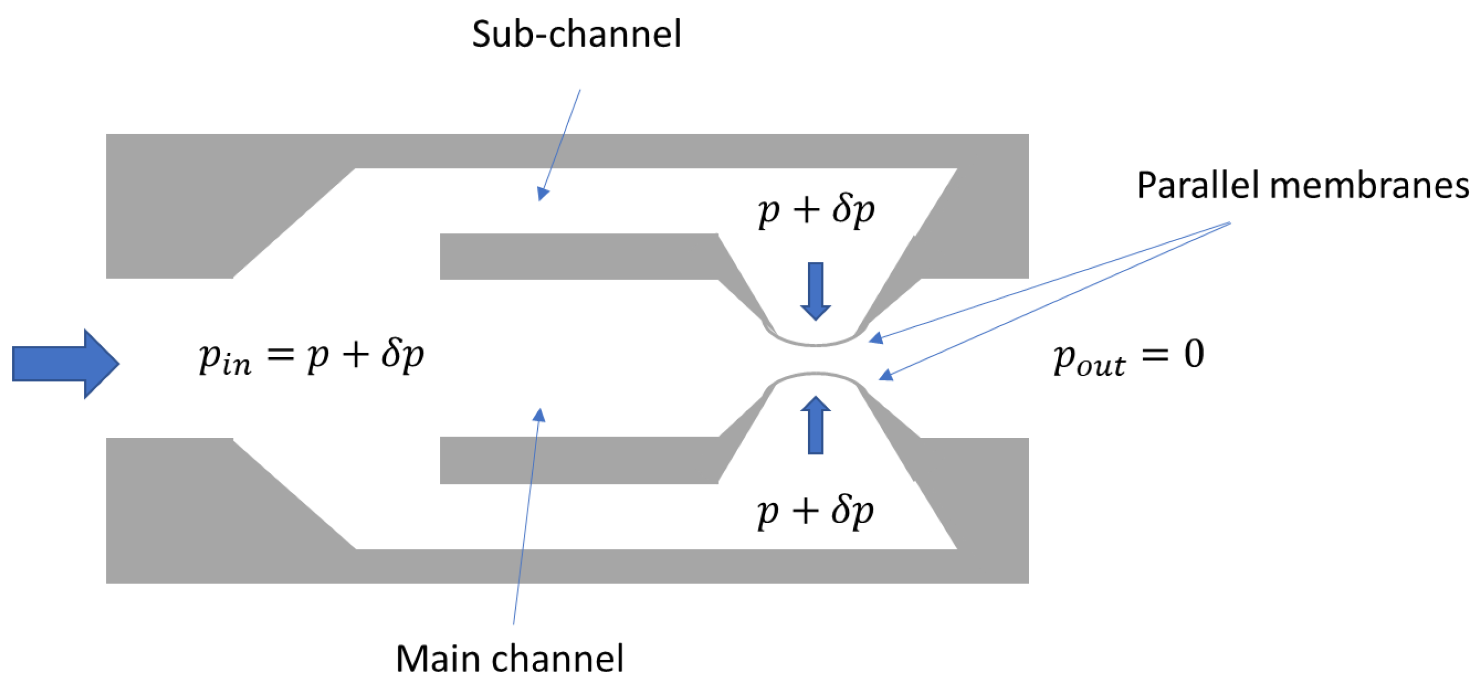
Contrary to the detour autoregulators, the hydraulic resistance of the devices considered in this sub-section occurs mainly in the part of the main channel where the compliant valve is positioned. In 2009, Doh et al. developed a passive flow regulator in PDMS using parallel membrane valves [42]. A schematic cross-section of the device is shown in Figure 8. The increase of both inlet and sub-channel (or control channel) pressures induces a deflection of the two membranes. The narrowing of the fluid path leads to an increase of the main channel hydraulic resistance. Both analytical and 3D FEM simulations were carried out to design the passive constant flow regulators. The working principle is thus similar to the detour autoregulator made by Kartalov’s group [37,39], except the fact that the pressure drop occurs here only in the space between the two thin membranes. The structure of the device is also simplified, and the minimum pressure to achieve flow regulation was lowered for better integration with micropumps.
A single mask process was used to fabricate the device in PDMS, with SU-8 negative photoresist structure as a mold master. The microchannel height of the different prototypes is and the main channel width is . The thin square membranes are thick. Four different prototypes having a width between the parallel membranes of and respectively, were tested with water. The prototype fabricated by PDMS (base/curing agent mixing ratio) and the prototype fabricated by PDMS showed a constant flow rate of in the pressure range and in the pressure range respectively. The other prototypes, including the prototype fabricated by 10:1 PDMS, did not show a constant flow rate. The prototypes made of PDMS, which exhibits a lower Young’s modulus than PDMS, showed, as expected, a lower threshold pressure and a higher regulated flow rate than their counterparts made of 10:1 PDMS [42].
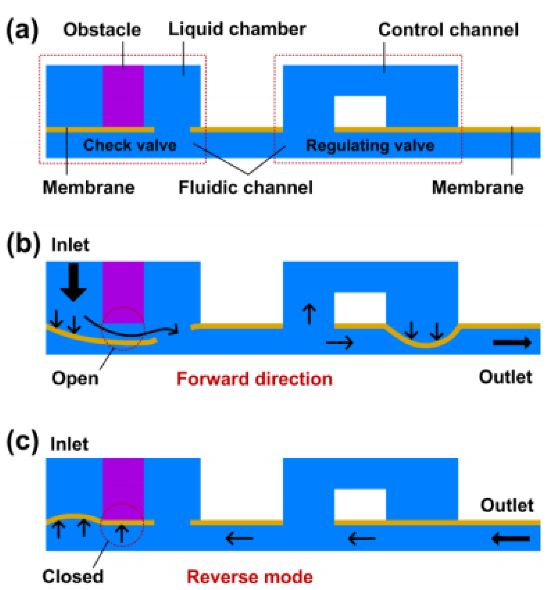
Zhang et al. further investigated this concept of passive flow regulators with elastomeric membranes and provided an analysis of the structural parameters that directly influence the flow rate [43,44,45,46]. Several passive flow regulators were built using standard soft lithography techniques [43,44], assembly of laser-structured thermoplastic films and PDMS membranes through roll-lamination method [45], or a combination of 3D printing and laser structuration/cutting [46]. PDMS, as a popular material for valve prototyping [47,48,49], was systematically used to form the thin membranes ( thick). Other layers are either made of PDMS [43,44], polyvinyl chloride (PVC) and polyethylene terephthalate (PET) [45], or photopolymer and silicon film [46]. The five-layer-stacked PDMS flow regulator comprises a bottom layer with a first control channel, a first membrane layer, a middle layer to form the main channel, a second membrane layer, and finally an upper layer with the second control channel and inlet and outlet ports [43,44]. The seven-layer-bond structure of the device made of PVC, PET, and PDMS comprises a base and a cover in PVC, and a fluidic layer in PVC between the upper and lower control layers in PET. Finally, the device made of photopolymer, a silicone film, and PDMS exhibits a four-layer structure with bottom and cover layers in photopolymer (structured using 3D printing technology), a seal layer in silicone, and the membrane in PDMS [46]. The working principle of this latter device, which furthermore comprises a check valve, is illustrated in Figure 9.
Zhang et al. manufactured and tested four different types of five-layer-stacked PDMS flow regulators noted with different membrane lengths (from to study the influence of the flexible membrane length on the flow rate (see Table A1 in Appendix A) [43]. and are respectively the width and the height of the contraction channel (i.e., valve) in , while represents the width of the two aligned control channels (i.e., valve length). All flow-rate characteristics were measured using water. When the length of the membrane increases from the threshold pressure and regulated flow rate decrease from and , respectively. Six other PDMS flow regulators were characterized to study the influence of the cross-sectional dimensions on the flow rate: three samples and three samples with , respectively. The measured regulated flow rates and threshold pressures are summarized in Table A1 in Appendix A. All results supported theoretical expectations: the stiffer the membrane, the higher the regulated flow rate and threshold pressure. As an example, increasing the height from (sample to (sample leads to a decrease of the threshold pressure from and an increase of the regulated flow rate from 1.12 [43]. Additional tests performed on a sample which exhibits, in static pressure conditions, a pressure threshold of and a regulated flow rate of , showed that the autoregulation performances are maintained under sinusoidal varied pressures in the range [44]. Another version of this passive flow regulator with a seven-layer-bond architecture for improved manufacturing capabilities was characterized by Zhang et al. [45]. In the pressure range , the devices with channel heights of and showed a regulated flow rate of respectively . The four-layer structure made using 3D printing and UV laser cutting technologies was finally considered for prototyping a passive flow regulator, using a PDMS membrane of in thickness, an obstacle in the seal-layer of and channel height and width of respectively . The device, dedicated to low-cost and portable lab-on-a-chip (LOC) applications, showed a constant flow rate of in the pressure range .
Device with a Notched Pin and a Moving Elastomeric Membrane with a Central Through-Hole
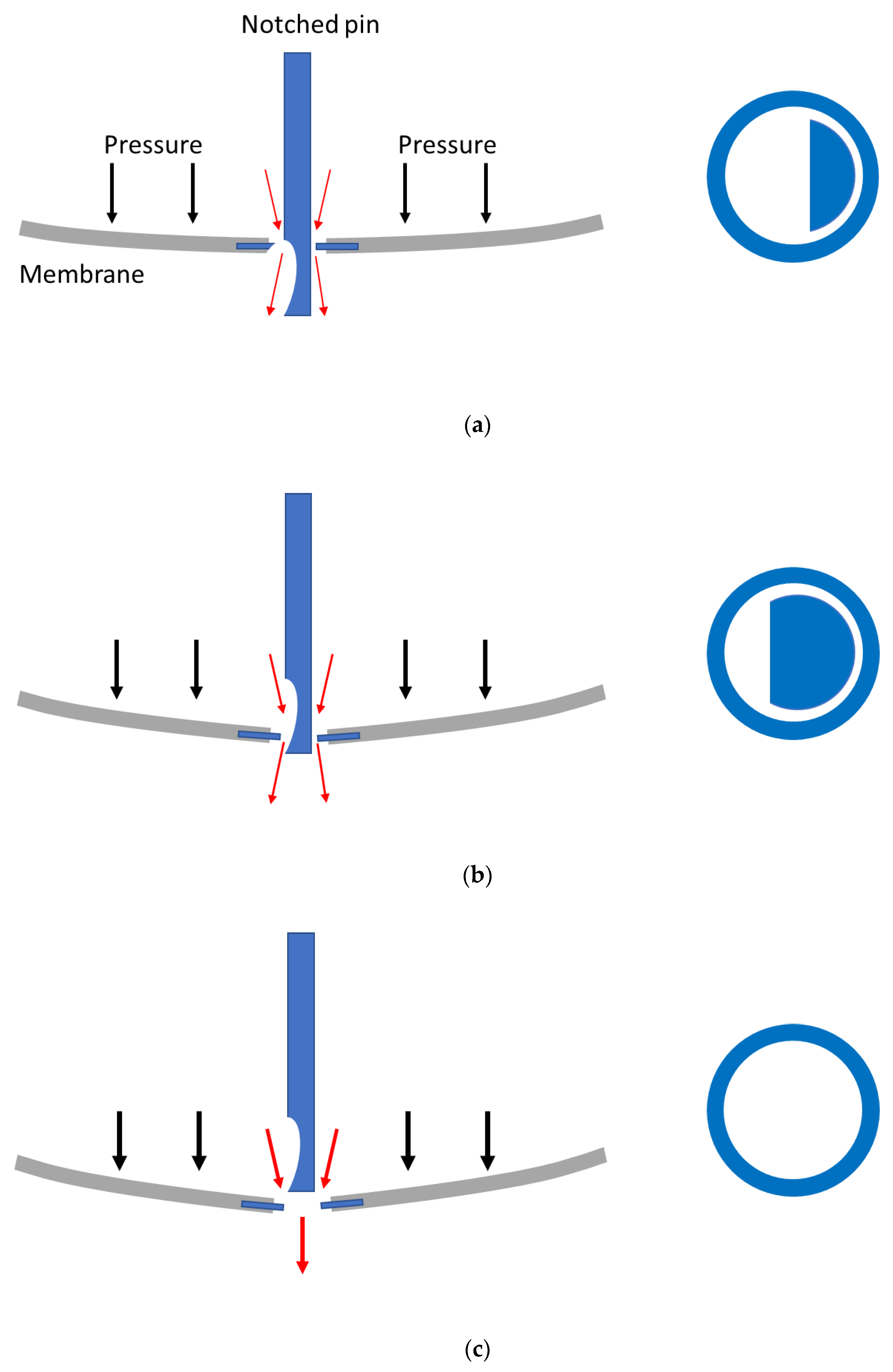
The first mention of a flow-controlled hydrocephalus shunt was made, to the best of the author’s knowledge, by Portnoy, who mentioned in 1982 that according to neurosurgeons’ comments, the ideal valve should be flow-controlled such as to only remove the excess of cerebrospinal fluid (CSF) [50]. The first valve based on this principle, that the flow through the shunt shall not exceed the CSF production rate throughout the range of physiological intracranial pressures (ICP), was designed by Sainte-rose et al. [51] and manufactured by Cordis Corporation. The valve labeled Orbis-Sigma® was first characterized in 1987 [51] and the later versions of this valve were included in many shunt evaluation campaigns (see, e.g., References [52,53,54,55]). A schematic drawing that illustrates the functioning principle of the valve is shown in Figure 10.
This passive flow-regulated valve has a flexible silicone membrane with a narrow orifice surrounding a pin of changing diameter. This three-stage valve has a fluidic characteristic similar to that of the passive high-flow regulator shown in Figure 2, with a regulated flow rate of about in the pressure range [55]. A low flow version (Integra NPH™) designed to meet the special needs of normal pressure hydrocephalus (NPH) patients requiring a lower flow rate of about , throughout a similar pressure range, is also marketed by Integra LifeSciences [56]. In the first stage, also called the differential pressure stage, the valve operates similarly to standard differential pressure valves with low hydraulic resistance. At higher pressure, in the flow regulating stage, the membrane goes down and the pin progressively reduces the orifice to maintain the flow constant. The third stage of the valve, in high-pressure conditions (above ), corresponds to the movement of the membrane beyond the pin. In this safety stage, the lowering of the hydraulic resistance enables a higher rate of CSF drainage to restore normal ICP.
3.2. Elastomeric Tubing with a Diamond-Shaped Aperture in the Sidewall
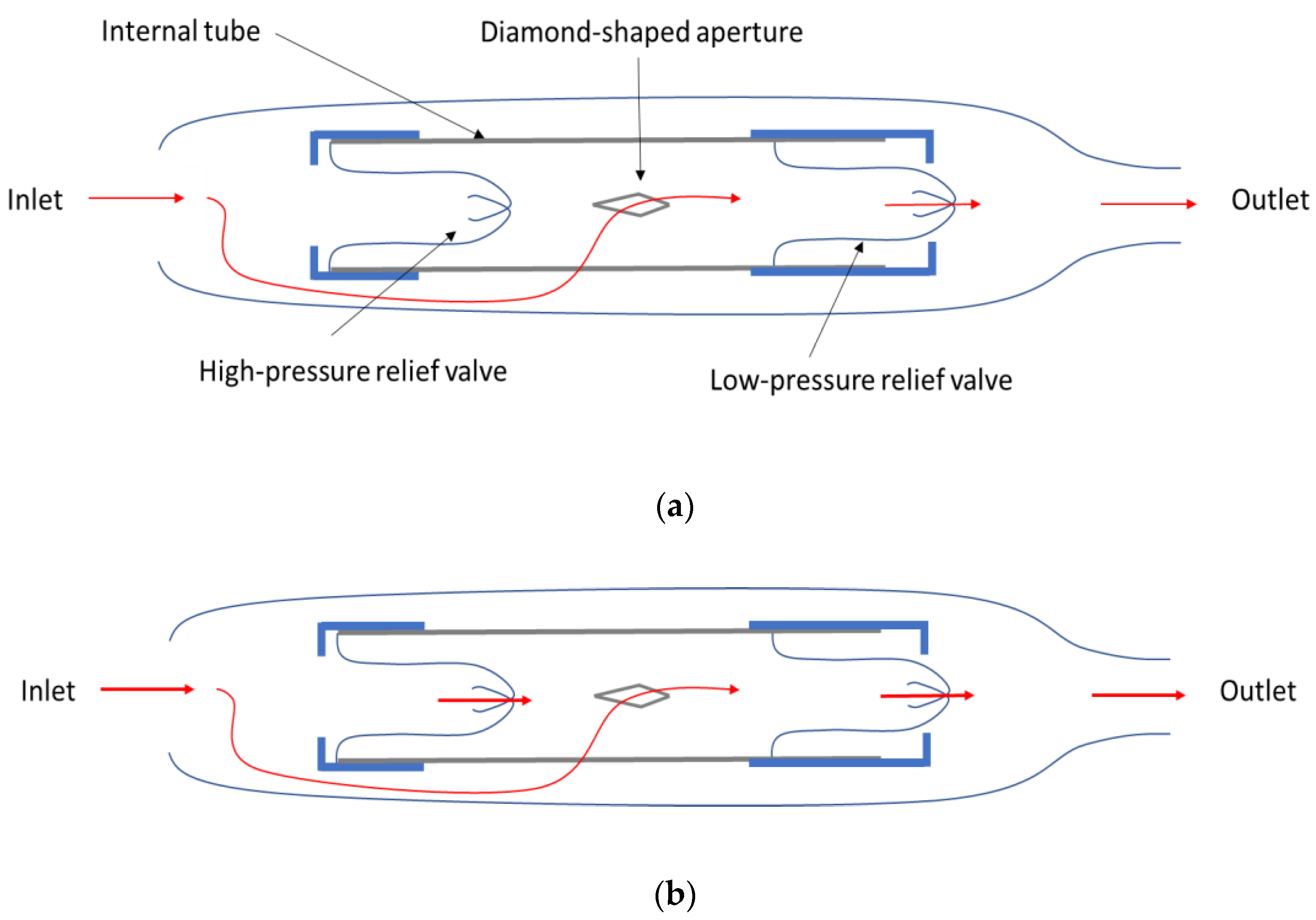
Another flow-controlled shunt design was disclosed by Paes in 1996 [8]. This CRx Diamond valve was manufactured by Phoenix Biomedical Corporation. The shunt mechanism, as illustrated in Figure 11, comprises a high-pressure relief valve (cruciform), an internal tube of an elastic wall forming the central channel with a diamond-shaped aperture in the sidewall, and a low-pressure outlet check valve (cruciform). As pressure increases, the tube contracts and narrows the side aperture. By design, the hydraulic resistance is expected to increase linearly with the pressure to regulate the flow. Beyond a predetermined threshold pressure, the high-pressure relief valve opens and the CSF flows through the wide central channel to restore normal ICP.
Laboratory evaluation of the CRx Diamond Valve demonstrated a stabilized flow within the range (for descending pressure) to (for ascending pressure) when pressure varied in the range . However, the stabilized flow decreased significantly over time, from to after 18 days. Czosnyka et al. also reported that the valve was insensitive to rapid fluctuations of differential pressure, small particles in the fluid, and reflux [57].
3.3. Spring Valve with a Spiral Groove on a Moving Piston
The design of the passive microfluidic devices described in the previous sections required two-dimensional (2D) or 3D FEM simulations of fluid flows fully coupled with structures undergoing large deformation, nonlinear material response, and contact conditions [58,59,60,61,62,63]. The non-well-defined Young’s Modulus of some elastomeric materials (e.g., PDMS), coupled with the difficult adaptative meshing of high aspect ratio structures, are a challenge in computational engineering. The complexity is also due to the nonlinear change of the hydraulic resistance of the fluid path as its cross-section is varied. Amacker et al. [16] and Cousseau et al. [30] already considered a long channel with a fixed cross-section but the calculation of the spiral shape, to achieve a linear increase of the channel length as the pressure increases, is difficult due to notably the highly nonlinear deformation of the membrane after contact with the substrate [64].
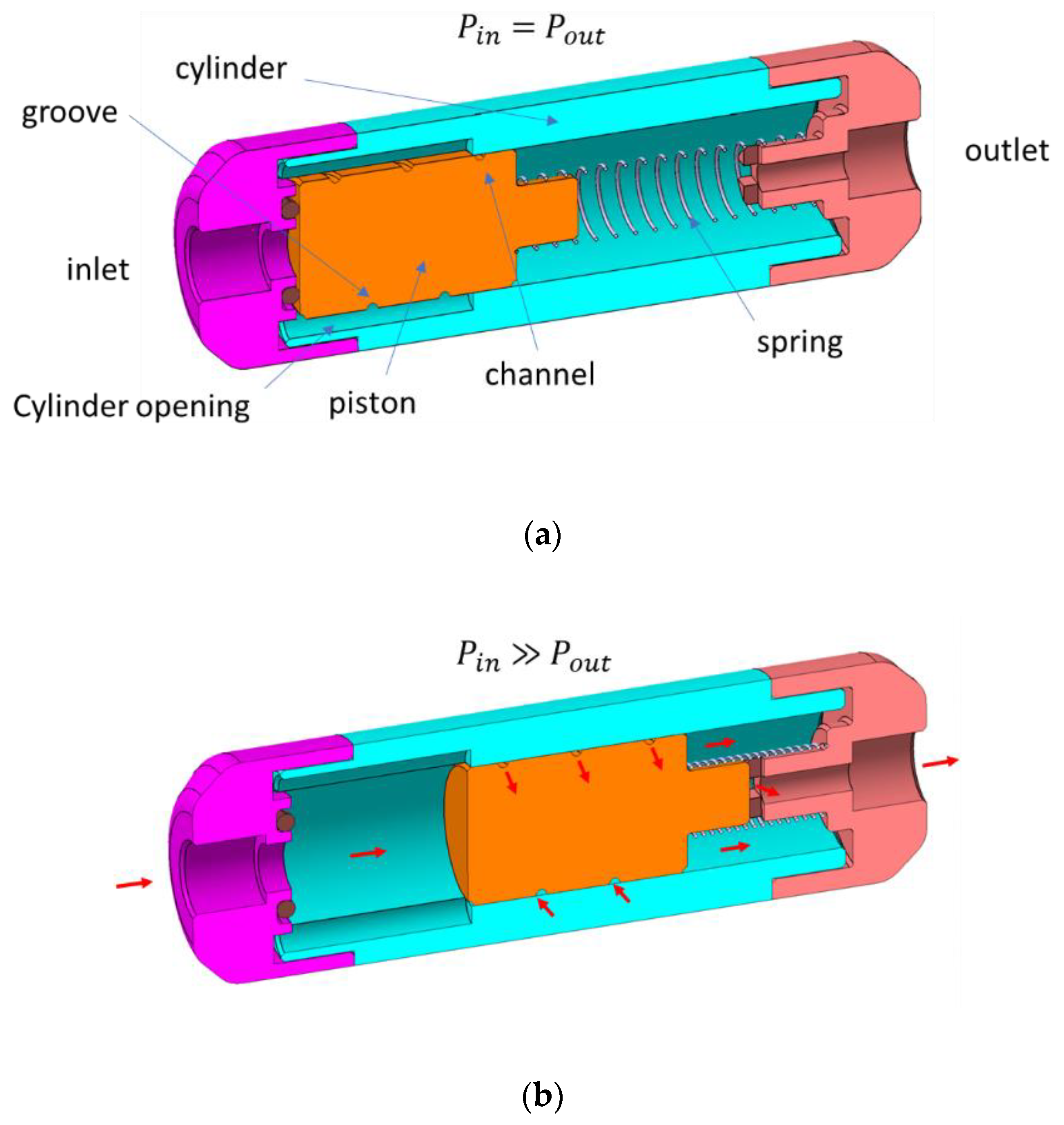
A simpler design consists of a moving cylinder with a spiral groove and a linear compression spring inside a hollow cylinder with openings (see Figure 12). Due to the spring pretension, a minimum threshold pressure shall be applied at the inlet to move the piston that is initially partly engaged into the narrow part of the cylinder. As the pressure force on the piston increases, the piston is engaged further into the narrow part of the cylinder and the fluid is forced to flow through a longer channel length. If the linear spring is maintained within its nominal compression range, the counterforce generated by the spring increases linearly with the applied pressure. The induced movement of the piston leads to a linear increase of the channel length as the pressure increases, and since the channel cross-section and spiral pitch are constant, the flow is regulated at a predetermined fixed value. At high pressure, the piston movement is stopped, and the hydraulic resistance of the device can be either fixed (as illustrated in Figure 12), infinite (flow stopped) if the piston completely obstructs the fluid path, or very low (free flow) if openings are machined along the outlet port of the cylinder to by-pass the channel [7]. The pressure threshold that delimits the flow regulating stage of this valve can be modified by adjusting, for instance, the pretension or the length of the spring.
Such a device structure, which is very well suited for a high throughput application (up to 4 L/min or more), was also considered for hydrocephalus treatment [7]. A prototype in titanium was designed to drain CSF from the brain ventricles toward the peritoneal cavity. The piston has a diameter of and the lathe tool with a tip curvature of and an angle of was used to form a deep spiral groove with a pitch of . The custom-made spring used for the test exhibited a stiffness larger than expected ( instead of N/m). The tests performed in a horizontal position using water at showed, after extrapolation at , a regulated flow rate of in the pressure range . The spring stiffness offset induced a slight positive slope in the curve in good agreement with the theoretical expectations. In a vertical position, the gravitational force acts either in the same or opposite direction as the pressure forces onto the piston. To limit the effect of this induced pressure offset on the flow rate, a specific hollow piston that exhibits an overall density equal to water density has been machined. This gravity force on this piston in polyether ether ketone (PEEK) is balanced by Archimedes’ force and the fluidic tests showed that the flow rate became insensitive to the device orientation.
The different parts of this passive constant flow regulating spring valve are compatible with standard machining techniques and can be characterized and sorted before the final assembly to improve the production yield. Given the impact of machining tolerances on flow rate accuracy, however, a minimum water flow rate of about should be targeted.
3.4. Device with a Thin Flexible Flap
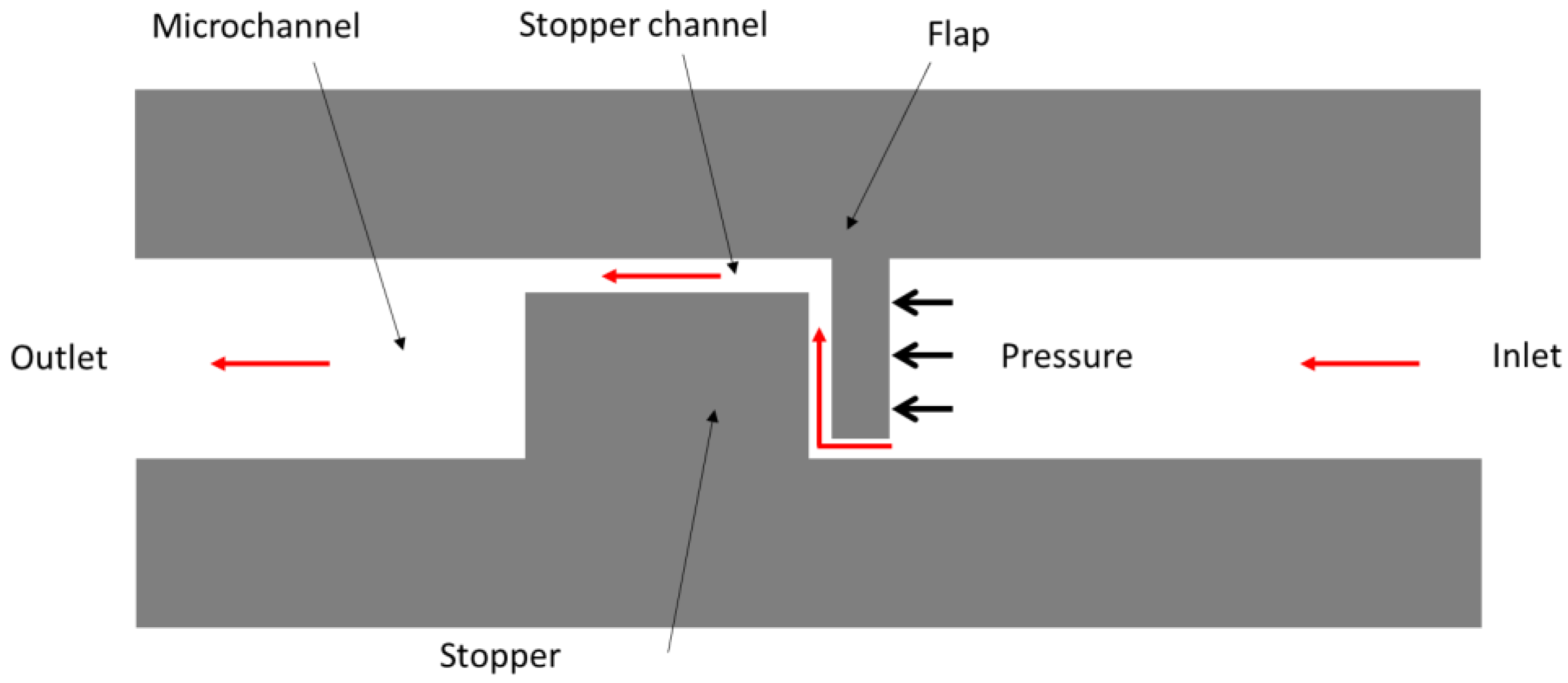
The final category of passive flow control devices to be considered in this section refers to microfluidic devices comprising a thin flexible flap and stiff stopper that form a flow constriction in a microchannel. Yang et al. considered a planar flap/stopper configuration, as illustrated in Figure 13 [65]. The flap deflects towards the stopper with the applied pressure and narrows the fluid constriction. The resulting increase of the hydraulic resistance compensates for the pressure variations to maintain the forward flow rate constant. For reverse flow, the device exhibits a small hydraulic resistance and diodicity (the ratio of the backward pressure drop to the forward pressure drop [66]) up to was measured experimentally [67].
This microfluidic variable resistor was fabricated in PDMS using standard replica molding techniques. The channel was formed by bonding the structured PDMS layer to flat PDMS or glass substrate(s) [65,67,68]. Yang et al. designed four different stopper/flap configurations: (a) basic design, as depicted in Figure 13, (b) centered stopper channel, (c) centered stopper channel with centered flap, and (d) double-flapped design [65]. All devices had a microchannel wide and high, a stopper channel long and wide, and a flap-free end away from the channel sidewall. The designs a, b, c, and d have a flap , , , and wide and , , , and away from the stopper, respectively. Flow rate measurements were performed with water. Constant flow rates of , and at in the pressure range were measured for the designs a, b, c, and d, respectively [65]. Two other configurations designed using 3D fluid–structure interaction simulations were fabricated and tested later by Yang et al. [67,68], the designs A and B with a flap and wide and and away from the stopper, respectively. Both designs had a microchannel wide and high, a flap wide and high, and a stopper channel long, wide, and high. The measured saturation threshold pressures are for design A and for design B. Constant flow rates of and at at pressure up to were reported for designs A and B, respectively.
Zhang et al. recently investigated a 3D-printed flap valve made of a photocurable resin [69]. The pressure-induced flap deflection narrows the flow restriction between the flap end and the microchannel sidewall. A theoretical model was developed to define the design rules. Using a flap with a tilt angle of , a thickness of , and an initial gap of , Zhang et al. measured, with water, a large constant flow rate of in the pressure range .
4. Non-Mechanical Passive Constant Flow Regulators
An original microfluidic passive flow regulator that can function at low Re without any moving parts was developed by Quake’s group at Caltech in 2003 [13,70]. The nonlinearity required, as discussed in Section 2, for a passive constant flow regulator, derived from the non-Newtonian elastic properties of the working fluid, a by weight aqueous solution of a high molecular weight polyacrylamide. Two different designs of nonlinear channels were fabricated in PDMS using soft lithography [17,18]. The first channel is a chain of 46 identical halves of broad ellipsoidal rings (with inner half axes of and and outer half axes of and ) interconnected by a narrow bottleneck (), while the second channel is a chain of 43 identical triangular segments (about ) interconnected by a bottleneck contraction of about . The viscoelastic solution is therefore forced to flow through a sequence of expansions and contractions. The polymer molecules become extended along the flow direction when the working fluid flows through a contraction. If the extension rate is large enough compared to (where is the relaxation time of the polymer solution), the molecules can unravel and generate nonlinearity with an increase of the apparent viscosity of the solution [71]. Both devices behave as a three-stage valve with two inflection points in the characteristics. The first device showed a linear increase in the flow rate with the pressure until a transition when the flow rate reaches . Constant flow rates of for a per segment in the range and for a per segment in the range are reported [13]. At higher pressure, the differential flow resistance decreases. The second device exhibited a flow transition at but the nonlinear increase of the resistance did not yield a flow stabilization when the pressure gradient per segment became larger than [70]. At low , the Navier-Stokes equations become linear and flow is expected to be completely reversible [72]. Therefore, the channel shall exhibit the same hydraulic resistance for both flow directions. Groisman demonstrated with the second device a diodicity of about 2, which was a signature, in absence of significant inertial effects, of a flow rectification due to nonlinear elastic properties of the working fluid [70]. Such devices may be integrated into a drug delivery system if a biocompatible polymer solution is used.
5. Conclusions
Active fluid control poses numerous problems of integration and miniaturization, and the development of microvalves and micropumps, which are two important building blocks of a microfluidic platform, was stimulated by recent advances in lab-on-a-chip for diagnostics applications, drug delivery, flow chemistry, point-of-care testing, etc. Compared to active microvalves [73], passive constant flow control valves provide a simpler way to regulate fluid flows without external control and energy consumption. This review has examined the wide variety of passive flow regulators that have been developed over the last 30 years. The modeling, the fabrication methods, and the resulting performance of these passive microvalves have been constantly improved. Table 2 summarized the principal pros and cons of each category of passive flow regulators.
Hysteresis was not included in this comparative table because this effect should be better characterized. Besides, considerations relative to the manufacturing reproducibility of the passive flow regulators made in PDMS are still speculative and have yet to be demonstrated. Recent advances in the development of these devices are promising but Table 2 also suggests that there is still room for further developing the technology and designing passive constant flow regulators that ideally combine the reliability and performance of MEMS-based valves with the ease of production and the large integration capability of their PDMS counterparts.
Funding
This research received no external funding.
Acknowledgments
The author would like to thank Dimitry Dumont-fillon for proof-reading the manuscript.
Conflicts of Interest
The author declares no conflict of interest.
Nomenclature
| Symbol | Name | Units |
| H | Height | m |
| L | Length | m |
| p | Pressure | Pa |
| Pin, Pout | Inlet/Outlet pressure | Pa |
| Δp | Pressure gradient | Pa |
| ΔPreg min, ΔPreg max | Minimum/Maximum pressure gradient to achieve the nominal flow rate | Pa |
| ΔPoff | Shut-off pressure gradient | Pa |
| Q, Q0 | Flow rate, Nominal flow rate | m3·s−1 |
| Rh | Hydrodynamic resistance | Pa·s·m−3 |
| T | Temperature | K |
| v | Velocity | m·s−1 |
| W | Width | m |
| η | Dynamic viscosity | Pa·s |
| Relaxation time of a polymer solution | s | |
| Re | Reynolds number | - |
| Kn | Knudsen number | - |
| Abbreviation | Name | |
| BioMEMS | Biomedical microelectromechanical system | |
| CSF | Cerebrospinal fluid | |
| CTQ | Critical-to-quality | |
| EOF | Electroosmotic flow | |
| FEM | Finite element method | |
| FSI | Fluid–structure interaction | |
| HF | Hydrofluoric acid | |
| ICP | Intracranial Pressure | |
| KOH | Potassium hydroxide | |
| LOC | Lab-on-a-chip | |
| MEMS | Microelectromechanical system | |
| NPH | Normal-pressure hydrocephalus | |
| PDMS | Poly(dimethylsiloxane) | |
| PE | Polyethylene | |
| PET | Polyethylene terephthalate | |
| PEEK | Polyether ether ketone | |
| PVC | Polyvinyl chloride | |
| Si | Silicon | |
| SOI | Silicon on insulator | |
| Ti | Titanium | |
| µTAS | Micro total analysis system |
Appendix A

Table A1.
Passive constant flow regulators.
| Author and Year | Name/Description | Construction | Working Fluid | Plateau Pressure (mbar) | Flow Rate (mL/min) | SD (%) | |
|---|---|---|---|---|---|---|---|
| Min | Max | ||||||
| MECHANICAL PASSIVE CONSTANT FLOW REGULATORS | |||||||
| Devices with Flexible Silicon Membrane(s) | |||||||
| Park 1988 [29] | Micromachined passive flow regulator | Rectangular Si membrane (h_channel 9.5 um, t_memb 26 um, L/W = 2) | Water | 200 | 400 | 0.0150 | n/r |
| Amacker 1998 [16] | Micromachined passive flow regulator | Membrane + spiral-shaped channel in Si/Pyrex or Titanium | Water | 100 | 600 | 0.0003 | 10.00 |
| Cousseau 2001 [30] | Passive flow regulator | Si membrane + spiral channel in Si substrate | Water | 180 | 500 | 0.0142 | 5.0 |
| Chappel 2014 [33] | Passive flow regulator | Drilled Si membrane + pillar substrate in Pyrex | Water | 50 | 150 | 0.225 | n/r |
| Cornaggia 2017 [22] | Passive flow regulator | Drilled Si membrane + pillar substrate in Pyrex (design A) | Water + Glycerol/12cP | 4000 | 21,000 | 0.6 | 5.0 |
| Drilled Si membrane + pillar substrate in Pyrex (design B) | Water + Glycerol/24cP | 8000 | 21,000 | 0.5 | 5.0 | ||
| Drilled Si membrane + pillar substrate in Pyrex (design C) | Water + Glycerol/24cP | 7000 | 21,000 | 0.13 | 5.0 | ||
| Conti 2018 [34] | Passive flow regulator | Drilled Si membrane + Si pillar substrate (design 1 mL/min at 12cP) | Water + Glycerol/12cP | 8000 | 19,000 | 0.95 | 5.0 |
| Drilled Si membrane + Si pillar substrate (design 0.2 mL/min at 24cP) | Water + Glycerol/24cP | 6000 | 19,000 | 0.21 | 5.0 | ||
| Dumont-fillon 2020 [9] | Passive flow regulator | 3-stack MEMS based device in Si and glass (1 mL/day design) | Water | 200 | 800 | 0.000694 | 10.0 |
| 3-stack MEMS based device in Si and glass (1 mL/h design) | Water | 200 | 800 | 0.0167 | 10.0 | ||
| Devices with Compliant Elastomeric Membrane(s) | |||||||
| Kartalov 2006 [37], Chang 2012 [39] | Detour autoregulator | PDMS channel + pushup valve (L2/L = 0.8) | Water | 620 | 1240 | 0.015 | n/r |
| PDMS channel + pushup valve (L2/L = 0.68) | Water | 620 | 1240 | 0.0198 | n/r | ||
| PDMS channel + pushup valve (L2/L = 0.57) | Water | 620 | 1240 | 0.0240 | n/r | ||
| Liu 2009 [38] | Detour autoregulator | PDMS channel + pushup valve (L2/L = 0.66, width 120 um) | Water | 350 | 620 | 0.0027 | n/r |
| PDMS channel + pushup valve (L2/L = 0.66, width 130 um) | Water | 280 | 620 | 0.0018 | n/r | ||
| PDMS channel + pushup valve (L2/L = 0.66, width 140 um) | Water | 210 | 620 | 0.0015 | n/r | ||
| Doh 2009 [42] | Parallel membrane valve | Thin PDMS membrane—width of 20 um | Water | 200 | 500 | 0.3654 | 3.8 * |
| Thin PDMS membrane—width of 40 um | Water | 150 | 500 | 0.8718 | 3.5 * | ||
| Zhang 2015 [43] | Passive flow regulator | Five-layer-stacked PDMS device—membrane (W200, L100, H75) in um | Water | 250 | 500 | 2.55 | 2.4 * |
| Five-layer-stacked PDMS device—membrane (W200, L200, H75) in um | Water | 250 | 500 | 2.06 | 3.9 * | ||
| Five-layer-stacked PDMS device—membrane (W200, L300, H75) in um | Water | 200 | 500 | 1.41 | 4.3 * | ||
| Five-layer-stacked PDMS device—membrane (W200, L400, H75) in um | Water | 150 | 500 | 1.12 | 4.5 * | ||
| Five-layer-stacked PDMS device—membrane (W100, L200, H75) in um | Water | 200 | 500 | 1.09 | 4.6 * | ||
| Five-layer-stacked PDMS device—membrane (W100, L300, H75) in um | Water | 200 | 500 | 0.92 | 4.4 * | ||
| Five-layer-stacked PDMS device—membrane (W100, L400, H75) in um | Water | 150 | 500 | 0.86 | 4.7 * | ||
| Five-layer-stacked PDMS device—membrane (W200, L200, H130) in um | Water | 150 | 500 | 4.38 | 2.3 * | ||
| Five-layer-stacked PDMS device—membrane (W200, L300, H130) in um | Water | 150 | 500 | 4.92 | 4.9 * | ||
| Five-layer-stacked PDMS device—membrane (W200, L400, H130) in um | Water | 100 | 500 | 2.79 | 4.7 * | ||
| Zhang 2016 [44] | Passive flow regulator | Five-layer-stacked PDMS device—membrane (W150, L300, H70) in um | Water | 250 | 500 | 1.49 | 1.2 * |
| Zhang 2017 [45] | Microfluidic autoregulatory valve (channel height 145 um) | Seven-layer-bond structure (polymer films and PDMS membranes) | Water | 200 | 700 | 1.36 | 3.4 * |
| Microfluidic autoregulatory valve (channel height 90 um) | Seven-layer-bond structure (polymer films and PDMS membranes) | Water | 200 | 700 | 0.29 | 4.2 * | |
| Zhang 2019 [46] | Passive flow regulator with check valve in reverse mode | Four-layer structure with thin PDMS membrane and silicone film | Water | 700 | 1300 | 25.2 | 5 * |
| Chari 2014 [55] | CSF shunt/Integra OSV II (Integra LifeScience)—normal flow | Moving elastomeric membrane + notched pin | Water (test)/CSF | 9 | 36 | 0.3 | 15.0 |
| Codman 2018 [56] | CSF shunt/Integra NPH (Integra LifeScience)—low flow | Moving elastomeric membrane + notched pin | Water (test)/CSF | 12 | 30 | 0.2 | n/r |
| Elastomeric Tubing with a Diamond-Shaped Aperture in the Sidewall | |||||||
| Paes 1996 [8], Czosnyka 2001 [57] | CSF shunt/CRx Diamond Valve (Phoenix Biomedical Corp.) | Elastomeric tube with a longitudinal aperture in the side wall | Water (test)/CSF | 18.6 | 30.6 | 0.63 (ascending pressure) | 50.0 |
| Elastomeric tube with a longitudinal aperture in the side wall | Water (test)/CSF | 18.6 | 30.6 | 0.36 (descending pressure) | 22.0 | ||
| Spring Valve with a Spiral Groove on a Moving Piston | |||||||
| Chappel 2016 [7] | CSF shunt/flow regulator | Titanium/PEEK spring valve with spiral groove on a moving cylinder | Water (test)/CSF | 10 | 35 | 0.35 | 5 * |
| Device with a Thin Flexible Flap | |||||||
| Yang 2004 [65] | Passive flow regulator in PDMS | PDMS flap + Stopper (design a: flap 60 um; d(flap-stopper) = 36 um | Water | 1000 | 2000 | 1.2 | 3.5 * |
| PDMS flap + Stopper (design b: flap 50 um; d(flap-stopper) = 40 um) | Water | 1000 | 2000 | 0.16 | 3.5 * | ||
| PDMS flap + Stopper (design c: flap 60 um; d(flap-stopper) = 45 um) | Water | 1000 | 2000 | 2.2 | 3.5 * | ||
| PDMS flap + Stopper (design d: flap 50 um; d(flap-stopper) = 50 um) | Water | 1000 | 2000 | 0.15 | 3.5 * | ||
| Yang 2007 [67], Yang 2007 [68] | Passive flow regulator in PDMS | PDMS flap + Stopper (design A: flap 60 um; d(flap-stopper) = 36 um) | Water | 600 | 2000 | 0.21 | 3.0 * |
| PDMS flap + Stopper (design B–flap 75 um; d(flap-stopper) = 25 um) | Water | 900 | 2000 | 1.2 | 3.0 * | ||
| Zhang 2020 [69] | Self-adaptative flexible valve as passive flow regulator | Flap (cantilever) in a channel | Water | 200 | 600 | 111 | 5.8 * |
| NON-MECHANICAL PASSIVE CONSTANT FLOW REGULATORS | |||||||
| Rheological | |||||||
| Groisman 2003 [13] | Non-linear resistor/Rheological | PDMS microchannels | Viscoelastic polymer solution | 10 | 100 | 0.0012 | 25.0 |
n/r: not reported; L2/L: detour channel ratio; * deviation to linearity measured on a single sample.
References
- Warring, R.H. Hydraulic Handbook; Gulf Publishing Company: Houston, TX, USA, 1983; pp. 117–119. [Google Scholar]
- Cundiff, J.S. Fluid Power Circuits and Controls: Fundamentals and Applications; CRC Press: Boca Raton, FL, USA, 2001; pp. 140–143. [Google Scholar]
- Laser, D.J.; Santiago, J.G. A review of micropumps. J. Micromech. Microeng. 2004, 14, R35–R64. [Google Scholar] [CrossRef]
- Whitesides, G.M. The origins and the future of microfluidics. Nature 2006, 442, 368–373. [Google Scholar] [CrossRef] [PubMed]
- White, F.M. Viscous Fluid Flow, 2nd ed.; McGraw-Hill: New York, NY, USA, 1991. [Google Scholar]
- Chappel, E. (Ed.) Drug Delivery Devices and Therapeutic Systems; Academic Press: New York, NY, USA, 2020. [Google Scholar]
- Chappel, E. Design and characterization of a passive flow control valve dedicated to the hydrocephalus treatment. Cogent Eng. 2016, 3, 1247612. [Google Scholar] [CrossRef]
- Paes, N.A. New self-adjusting flow-regulating device for shunting of CSF. Childs Nerv. Syst. 1996, 12, 619–625. [Google Scholar] [CrossRef] [PubMed]
- Dumont-Fillon, D.; Lamaison, D.; Chappel, E. Design and characterization of 3-stack MEMS-based passive flow regulators for implantable and ambulatory infusion pumps. J. Microelectromech. Syst. 2020, 29, 170–181. [Google Scholar] [CrossRef]
- Skryabina, E.A.; Dunn, T.S. Disposable infusion pumps. Am. J. Health-Syst. Pharm. 2006, 63, 1260–1268. [Google Scholar] [CrossRef]
- Capes, D.F.; Asiimwe, D. Performance of selected flow-restricting infusion devices. Am. J. Health Syst. Pharm. 1998, 55, 351–359. [Google Scholar] [CrossRef]
- Ilfeld, B.M.; Morey, T.E.; Enneking, F.K. The delivery rate accuracy of portable infusion pumps used for continuous regional analgesia. Anesth. Analg. 2002, 95, 1331–1336. [Google Scholar] [CrossRef]
- Groisman, A.; Enzelberger, M.; Quake, S.R. Microfluidic memory and control devices. Science 2003, 300, 955–958. [Google Scholar] [CrossRef] [Green Version]
- Roy, S.; Raju, R.; Chuang, H.F.; Cruden, B.A.; Meyyappan, M. Modeling gas flow through microchannels and nanopores. J. Appl. Phys. 2003, 93, 4870–4879. [Google Scholar] [CrossRef]
- Kestin, J.; Sokolov, M.; Wakeham, W.A. Viscosity of liquid water in the range −8 °C to 150 °C. J. Phys. Chem. Ref. Data 1978, 7, 941–948. [Google Scholar] [CrossRef] [Green Version]
- Amacker, C.; Leung Ki, Y.-S.; Pasquier, V.; Madore, C.; Haller, M.; Renaud, P.; White, N. Passive micro-flow regulator for drug delivery system. In Proceedings of the Eurosensors XII Conference, Southampton, UK, 13–16 September 1998; pp. 591–594. [Google Scholar]
- Duffy, D.C.; McDonald, J.C.; Schueller, O.J.; Whitesides, G.M. Rapid prototyping of microfluidic systems in poly (dimethylsiloxane). Anal. Chem. 1998, 70, 4974–4984. [Google Scholar] [CrossRef] [PubMed]
- McDonald, J.C.; Duffy, D.C.; Anderson, J.R.; Chiu, D.T.; Wu, H.; Schueller, O.J.; Whitesides, G.M. Fabrication of microfluidic systems in poly (dimethylsiloxane). Electrophoresis 2000, 21, 27–40. [Google Scholar] [CrossRef]
- Sackmann, E.K.; Fulton, A.L.; Beebe, D.J. The present and future role of microfluidics in biomedical research. Nature 2014, 507, 181–189. [Google Scholar] [CrossRef]
- Quake, S.R.; Scherer, A. From micro-to nanofabrication with soft materials. Science 2000, 290, 1536–1540. [Google Scholar] [CrossRef] [Green Version]
- Petersen, K.E. Silicon as a mechanical material. Proc. IEEE 1982, 70, 420–457. [Google Scholar] [CrossRef]
- Cornaggia, L.; Conti, L.; Hannebelle, M.; Gamper, S.; Dumont-Fillon, D.; Van Lintel, H.; Renaud, P.; Chappel, E. Passive flow control valve for protein delivery. Cogent Eng. 2017, 4, 1413923. [Google Scholar] [CrossRef]
- Oseyemi, A.E.; Zhang, X. Theoretical modeling of the behavior of a parallel membrane passive flow regulator. Sens. Actuator A Phys. 2020, 315, 112310. [Google Scholar] [CrossRef]
- Dumont-Fillon, D.; Hannebelle, M.; Van Lintel, H.; Chappel, E. Design of a passive flow regulator using a genetic algorithm. Procedia Eng. 2016, 168, 1016–1019. [Google Scholar] [CrossRef]
- Zengerle, R.; Richter, M. Simulation of microfluid systems. J. Micromech. Microeng. 1994, 4, 192–204. [Google Scholar] [CrossRef]
- Bourouina, T.; Grandchamp, J.-P. Modeling micropumps with electrical equivalent networks. J. Micromech. Microeng. 1996, 6, 398–404. [Google Scholar] [CrossRef] [Green Version]
- Chappel, E.; Hannebelle, M.; Cornaggia, L.; Dumont-Fillon, D.; Momjian, S. Hybrid hydrodynamic characteristic for hydrocephalus valve: A numerical investigation using electrical equivalent networks. Cogent Eng. 2017, 4, 1415103. [Google Scholar] [CrossRef]
- Tachatos, N.; Chappel, E.; Dumont-Fillon, D.; Meboldt, M.; Daners, M.S. Posture related in-vitro characterization of a flow regulated MEMS CSF valve. Biomed. Microdevices 2020, 22, 1–12. [Google Scholar] [CrossRef]
- Park, S.; Ko, W.; Prahl, J. A Constant flow-rate microvalve actuator based on silicon and micromachining technology. In Proceedings of the IEEE Technical Digest on Solid-State Sensor and Actuator Workshop, Hilton Head Island, SC, USA, 6–9 June 1988; pp. 136–139. [Google Scholar]
- Cousseau, P.; Hirschi, R.; Frehner, B.; Gamper, S.; Maillefer, D. Improved micro-flow regulator for drug delivery systems. In Proceedings of the 14th IEEE International Conference on Micro Electro Mechanical Systems MEMS 2001, Interlaken, Switzerland, 21–25 January 2001; pp. 527–530. [Google Scholar]
- Chappel, E. Passive Fluid Flow Regulator. U.S. Patent US8539981 (B2), 24 September 2013. [Google Scholar]
- Chappel, E.; Musard, H.; Dumont-fillon, D. Experimental characterization and modelling of microfluidic radial diffusers for passive self-regulating valves. Glob. J. Eng. Tech. Adv. 2019, 1, 10–21. [Google Scholar] [CrossRef]
- Chappel, E.; Dumont-Fillon, D.; Mefti, S. Passive flow regulators for drug delivery and hydrocephalus treatment. In Proceedings of the Microfluidics, BioMEMS, and Medical Microsystems XII Conference (International Society for Optics and Photonics), San Francisco, CA, USA, 2–4 February 2014; Volume 8976, p. 89760S. [Google Scholar]
- Conti, L.; Dumont-Fillon, D.; van Lintel, H.; Chappel, E. Silicon-to-silicon anodic bonding via intermediate borosilicate layer for passive flow control valves. Int. J. Mech. Ind. Aero. Sci. 2018, 12, 701–704. [Google Scholar]
- Chappel, E. Adjustable Passive Flow Regulator. European Patent EP2943708B1, 6 September 2017. [Google Scholar]
- Yang, B.; Metier, J.L.; Lin, Q. Using compliant membranes for dynamic flow stabilization in microfluidic systems. In Proceedings of the 18th IEEE International Conference on Micro Electro Mechanical Systems MEMS 2005, Miami Beach, FL, USA, 30 January–3 February 2005; pp. 706–709. [Google Scholar]
- Kartalov, E.P.; Walker, C.; Taylor, C.R.; Anderson, W.F.; Scherer, A. Microfluidic vias enable nested bioarrays and autoregulatory devices in newtonian fluids. Proc. Natl. Acad. Sci. USA 2006, 103, 12280–12284. [Google Scholar] [CrossRef] [PubMed] [Green Version]
- Liu, J.; Chen, Y.; Taylor, C.R.; Scherer, A.; Kartalov, E.P. Elastomeric microfluidic diode and rectifier work with newtonian fluids. J. Appl. Phys. 2009, 106, 114311. [Google Scholar] [CrossRef] [Green Version]
- Chang, H.-J.; Ye, W.; Kartalov, E.P. Quantitative modeling of the behaviour of microfluidic autoregulatory devices. Lab. Chip 2012, 12, 1890–1896. [Google Scholar] [CrossRef]
- Kartalov, E.P.; Scherer, A.; Quake, S.R.; Taylor, C.R.; Anderson, W.F. Experimentally validated quantitative linear model for the device physics of elastomeric microfluidic valves. J. Appl. Phys. 2007, 101, 064505. [Google Scholar] [CrossRef] [Green Version]
- Gervais, T.; El-Ali, J.; Günther, A.; Jensen, K.F. Flow-induced deformation of shallow microfluidic channels. Lab. Chip 2006, 6, 500–507. [Google Scholar] [CrossRef] [Green Version]
- Doh, I.; Cho, Y.H. Passive flow-rate regulators using pressure-dependent autonomous deflection of parallel membrane valves. Lab. Chip 2009, 9, 2070–2075. [Google Scholar] [CrossRef] [PubMed]
- Zhang, X.; Xiang, N.; Tang, W.; Huang, D.; Wang, X.; Yi, H.; Ni, Z. A passive flow regulator with low threshold pressure for high-throughput inertial isolation of microbeads. Lab. Chip 2015, 15, 3473–3480. [Google Scholar] [CrossRef] [PubMed]
- Zhang, X.; Wang, X.; Chen, K.; Cheng, J.; Xiang, N.; Ni, Z. Passive flow regulator for precise high-throughput flow rate control in microfluidic environments. RSC Adv. 2016, 6, 31639–31646. [Google Scholar] [CrossRef]
- Zhang, X.; Zhu, Z.; Ni, Z.; Xiang, N.; Yi, H. Inexpensive, rapid fabrication of polymer-film microfluidic autoregulatory valve for disposable microfluidics. Biomed. Microdevices 2017, 19, 21. [Google Scholar] [CrossRef] [PubMed]
- Zhang, X.; Zhang, Z. Microfluidic passive flow regulatory device with an integrated check valve for enhanced flow control. Micromachines 2019, 10, 653. [Google Scholar] [CrossRef] [PubMed] [Green Version]
- Kawai, K.; Arima, K.; Morita, M.; Shoji, S. Microfluidic valve array control system integrating a fluid demultiplexer circuit. J. Micromech. Microeng. 2015, 25, 065016. [Google Scholar] [CrossRef]
- Hansson, J.; Hillmering, M.; Haraldsson, T.; van der Wijngaart, W. Leak-tight vertical membrane microvalves. Lab. Chip 2016, 16, 1439–1446. [Google Scholar] [CrossRef]
- Rho, H.S.; Yang, Y.; Hanke, A.T.; Ottens, M.; Terstappen, L.W.; Gardeniers, H. Programmable V-type valve for cell and particle manipulation in microfluidic devices. Lab. Chip 2016, 16, 305–311. [Google Scholar] [CrossRef]
- Portnoy, H.D. Hydrodynamics of shunts. Monogr. Neural Sci. 1982, 8, 179–183. [Google Scholar]
- Sainte-Rose, C.; Hooven, M.D.; Hirsch, J.-F. A New approach in the treatment of hydrocephalus. J. Neurosurg. 1987, 66, 213–226. [Google Scholar] [CrossRef] [Green Version]
- Drake, J.M.; Kestle, J. Rationale and methodology of the multicenter pediatric cerebrospinal sluid shunt design trial. Child’s Nerv. Syst. 1996, 12, 434–447. [Google Scholar] [CrossRef] [PubMed]
- Drake, J.M.; Kestle, J.R.; Milner, R.; Cinalli, G.; Boop, F.; Piatt, J.; Haines, S.; Schiff, S.J.; Cochrane, D.D.; Steinbok, P. Randomized trial of cerebrospinal fluid shunt valve design in pediatric hydrocephalus. Neurosurgery 1998, 43, 294–303. [Google Scholar] [CrossRef] [Green Version]
- Hanlo, P.W.; Cinalli, G.; Vandertop, W.P.; Faber, J.A.; Bøgeskov, L.; Børgesen, S.E.; Boschert, J.; Chumas, P.; Eder, H.; Pople, I.K. Treatment of hydrocephalus determined by the european orbis sigma valve II survey: A multicenter prospective 5-year shunt survival study in children and adults in whom a flow-regulating shunt was used. J. Neurosurg. 2003, 99, 52–57. [Google Scholar] [CrossRef] [PubMed]
- Chari, A.; Czosnyka, M.; Richards, H.K.; Pickard, J.D.; Czosnyka, Z.H. Hydrocephalus shunt technology: 20 years of experience from the Cambridge shunt evaluation laboratory. J. Neurosurg. 2014, 120, 697–707. [Google Scholar] [CrossRef] [PubMed]
- Codman specialty surgical. In Flow Regulating Valves; Integra LifeSciences Corporation: Princeton, NJ, USA, 2018.
- Czosnyka, Z.H.; Czosnyka, M.; Richards, H.K.; Pickard, J.D. Laboratory evaluation of the Phoenix CRx diamond valve. Neurosurg. 2001, 48, 689–694. [Google Scholar] [CrossRef] [PubMed]
- Senturia, S.D. CAD Challenges for microsensors, microactuators, and microsystems. Proc. IEEE 1998, 86, 1611–1626. [Google Scholar] [CrossRef]
- Oosterbroek, R.; Berenschot, J.W.; Schlautmann, S.; Lammerink, T.S.; van den Berg, A.; Elwenspoek, M.C. Modeling and validation of fluid structure interactions in passive micro valves. In Proceedings of the 1998 International Conference on modelling and Simulation of Microsystems Semiconductors, Santa Clara, CA, USA, 6–8 April 1998; pp. 528–533. [Google Scholar]
- Dowell, E.H.; Hall, K.C. Modeling of fluid-structure interaction. Annu. Rev. Fluid Mech. 2001, 33, 445–490. [Google Scholar] [CrossRef]
- Smal, O.; Raucent, B.; Jeanmart, H. Fluid flow modelling of a micro-valve. Int. J. Simul. Multidiscip. Des. Optim. 2009, 3, 356–362. [Google Scholar] [CrossRef]
- Chakraborty, D.; Prakash, J.R.; Friend, J.; Yeo, L. Fluid-structure interaction in deformable microchannels. Physics Fluids 2012, 24, 102002. [Google Scholar] [CrossRef] [Green Version]
- Lin, Z.-H.; Li, X.-J.; Jin, Z.-J.; Qian, J.-Y. Fluid-structure interaction analysis on membrane behavior of a microfluidic passive valve. Membranes 2020, 10, 300. [Google Scholar] [CrossRef]
- Timoshenko, S.P.; Woinowsky-Krieger, S. Theory of Plates and Shells, 2nd ed.; McGraw-Hill: New York, NY, USA, 1959; pp. 308–310. [Google Scholar]
- Yang, B.; Levis, J.W.; Lin, Q. A PDMS-based constant-flowrate microfluidic control device. In Proceedings of the 17th IEEE Internationl Conference MEMS 2004, Maastricht, The Netherlands, 25–29 January 2004; pp. 379–382. [Google Scholar]
- Fadl, A.; Zhang, Z.; Geller, S.; Tölke, J.; Krafczyk, M.; Meyer, D. The effect of the microfluidic diodicity on the efficiency of valve-less rectification micropumps using lattice boltzmann method. Microsyst. Technol. 2009, 15, 1379–1387. [Google Scholar] [CrossRef]
- Yang, B.; Lin, Q. Planar micro-check valves exploiting large polymer compliance. Sens. Actuator A Phys. 2007, 134, 186–193. [Google Scholar] [CrossRef]
- Yang, B.; Lin, Q. A planar compliance-based self-adaptive microfluidvariable resistor. J. Microelectromech. Syst. 2007, 16, 411–419. [Google Scholar] [CrossRef]
- Zhang, Q.; Peng, X.; Weng, S.; Zhang, R.; Fang, D.; Zhao, R.; Qi, H.J. Self-adaptive flexible valve as passive flow regulator. Extreme Mech. Lett. 2020, 39, 100824. [Google Scholar] [CrossRef]
- Groisman, A.; Quake, S.R. A Microfluidic rectifier: Anisotropic flow resistance at low reynolds numbers. Phys. Rev. Lett. 2004, 92, 094501. [Google Scholar] [CrossRef] [Green Version]
- Tirtaatmadja, V.; Sridhar, T. A filament stretching device for measurement of extensional viscosity. J. Rheol. 1993, 37, 1081–1102. [Google Scholar] [CrossRef]
- Landau, L.; Lifshitz, E. Fluid Mechanics, 2nd ed.; Pergamon Press: New York, NY, USA, 1987. [Google Scholar]
- Oh, K.W.; Ahn, C.H. A review of microvalves. J. Micromech. Microeng. 2006, 16, R13–R39. [Google Scholar] [CrossRef]
Figure 1.
Classification of the passive constant flow regulators dedicated to microfluidic applications.
Figure 1.
Classification of the passive constant flow regulators dedicated to microfluidic applications.

Figure 2.
Ideal flow rate versus pressure gradient characteristic of a three-stage passive constant flow regulator. At low pressure (stage I), the regulator has a constant and low hydraulic resistance. In stage II, the flow is regulated at for a pressure gradient in the range At high pressure (stage III), the device could, according to its specific design, either stop the flow at (solid line) or conversely, deliver a large flow rate (dashed line).

Figure 3.
Schematic cross-section of a triple-stack passive flow regulator, with a Si wafer (membrane), bonded to the inlet and outlet Pyrex covers. The flow direction is indicated by red arrows. The fluid is forced to flow through the gap (or channel) between the membrane and the bottom cover that narrows as the pressure increases. As a result, the flow–pressure relationship becomes nonlinear.

Figure 4.
Cross-section of a triple-stack passive flow regulator, with a top Pyrex wafer (inlet port), a middle Si wafer (membrane), and a bottom Si or Pyrex wafer (substrate with a spiral microflow channel and an outlet port). As the pressure increases, the Si membrane deflects against the substrate and forces the fluid flow through the spiral channel. By design, the membrane covers a channel length that increases linearly with the applied pressure to maintain a constant flow rate (Courtesy of Debiotech SA, Switzerland).

Figure 5.
Cross-section of a passive flow regulator with a top SOI wafer (membrane) and a bottom wafer (substrate) made of Pyrex or Si. The fluid flows through the inlet holes of the membrane, the radial diffuser (annular restriction between the membrane and the pillar), and the outlet hole of the substrate. As the pressure increases, the deflection of the membrane induces an increase in the hydraulic resistance of the radial diffuser to keep the flow rate constant. The flow direction is indicated by red arrows.

Figure 6.
Schematic cross-section of a triple-stack microfluidic device dedicated to drug delivery at a constant flow rate of less than , with a top SOI wafer (membrane), an intermediate borosilicate layer, a middle Si wafer (substrate) comprising pillars, through holes and microchannels, and a bottom borosilicate wafer with inlet and outlet ports. The top surface of the membrane and the inlet ports are in direct communication with the pressurized reservoir. The direction of the flow is indicated by red arrows. As the pressure increases, the gap between the membrane and the pillars (i.e., the radial diffusers) narrows and the hydraulic resistance of the device increases to keep the flow rate constant (adapted from Reference [9]).

Figure 7.
Schematic drawing of a microfluidic current source in PDMS comprising a main channel, a detour channel, and a pushup valve. The flow direction is indicated by the arrow (forward bias). The main and detour channel lengths are noted and , respectively. The increase of the inlet pressure generates a larger pressure drop along the main channel and thus the pushup valve will progressively obstruct the main channel and lead, beyond a saturation pressure, to a constant flow rate (adapted from Reference [39]).

Figure 8.
Schematic drawing of a passive flow regulator using autonomous deflection of parallel membrane valves. The increase of the inlet pressure induces a deflection of two membranes and thus an increase of the hydraulic resistance of the device (adapted from Reference [42]).
Figure 8.
Schematic drawing of a passive flow regulator using autonomous deflection of parallel membrane valves. The increase of the inlet pressure induces a deflection of two membranes and thus an increase of the hydraulic resistance of the device (adapted from Reference [42]).

Figure 9.
The working principle of the microfluidic device with a check valve and a flow regulating valve in PDMS. (a) Concept of the microchannel structure of the device at rest. (b) In the forward mode, the check valve is open and a flow regulating valve controls the liquid flowing through the microchannel. (c) In the reverse mode, the check valve is closed, and the flow is stopped (reprinted from Reference [46], Copyright MDPI).

Figure 10.
Schematic drawings of Orbis-Sigma II® valve (left) and cross-section of the orifice between the membrane and the pin (right). The cerebrospinal fluid (CSF) flow is indicated by an arrow. (a) Differential pressure stage, with a low hydraulic resistance up to . (b) Flow regulating stage, with a progressive narrowing of the orifice as the pressure increases from to . (c) Safety stage beyond with a low hydraulic resistance to restore normal ICP.

Figure 11.
Schematic drawing of the CRx Diamond Valve, a flow control hydrocephalus shunt. The arrows indicate the flow direction. (a) Flow regulation stage, i.e., for pressure in the range . The CSF flows through the diamond-shaped aperture that narrows as the pressure increases to induce nonlinearity and through the low-pressure relief valve. (b) High-pressure or safety stage. The high-pressure relief valve opens to drain the excess of CSF through the large channel and the low-pressure relief valve.

Figure 12.
Schematic drawings of a constant flow regulating spring valve. (a) Device at rest. A small part of the piston groove is engaged into the narrow part of the cylinder to form a fluidic channel. (b) Device submitted to a large pressure As the inlet pressure increases, the piston moves along the cylinder and the channel length increases as well. At large pressure, the piston is stopped and the hydraulic resistance of the device becomes constant.

Figure 13.
Schematic top view of a planar PDMS microfluidic flow regulator. The flow direction is indicated by red arrows. The flow restriction between the flap narrows with the applied pressure to maintain the flow rate constant.
Figure 13.
Schematic top view of a planar PDMS microfluidic flow regulator. The flow direction is indicated by red arrows. The flow restriction between the flap narrows with the applied pressure to maintain the flow rate constant.

Table 1.
Effect of dynamic viscosity change with temperature on relative flow rate accuracy of passive constant flow regulators. The reference temperature is
Table 1.
Effect of dynamic viscosity change with temperature on relative flow rate accuracy of passive constant flow regulators. The reference temperature is
| Temperature (°C) | 5 | 10 | 15 | 20 | 25 | 30 | 35 | 40 |
|---|---|---|---|---|---|---|---|---|
| Water dynamic viscosity (mPa·s) | 1.520 | 1.308 | 1.139 | 1.002 | 0.890 | 0.797 | 0.719 | 0.653 |
| Relative water flow rate error (%) | −34.1% | −23.4% | −12.0% | 0.0% | 12.6% | 25.7% | 39.3% | 53.5% |
Table 2.
Comparative table of the different categories of passive constant flow regulators.
| Pressure Range | Flow Rate Range | Accuracy/Reproducibility | Connectivity | Fabrication Cost | Prototyping Complexity | Aqueous Solution | |
|---|---|---|---|---|---|---|---|
| MECHANICAL | |||||||
| Si membrane(s) | Very large | Very large | High/Very High | Medium | Low */High | High | Yes |
| Elastomeric membrane(s) | Large | Very large | High/Medium ** | High | Low/Medium | Low/Medium | Yes |
| Tube with lateral aperture | Small | Small | Low/Low | Medium | Low | Low | Yes |
| Piston | Large | Large | High/Medium ** | Medium | Medium | Medium | Yes |
| Flap | Large | Large | High/Medium ** | High | Low/Medium | Low/Medium | Yes |
| NON-MECHANICAL | |||||||
| Rheological | Small | Small | Low/Medium ** | High | Low | Low | No |
* At large volumes only; ** Estimation.
Publisher’s Note: MDPI stays neutral with regard to jurisdictional claims in published maps and institutional affiliations. |
© 2020 by the author. Licensee MDPI, Basel, Switzerland. This article is an open access article distributed under the terms and conditions of the Creative Commons Attribution (CC BY) license (http://creativecommons.org/licenses/by/4.0/).
Share and Cite
MDPI and ACS Style
Chappel, E. A Review of Passive Constant Flow Regulators for Microfluidic Applications. Appl. Sci. 2020, 10, 8858. https://doi.org/10.3390/app10248858
AMA Style
Chappel E. A Review of Passive Constant Flow Regulators for Microfluidic Applications. Applied Sciences. 2020; 10(24):8858. https://doi.org/10.3390/app10248858
Chicago/Turabian StyleChappel, Eric. 2020. "A Review of Passive Constant Flow Regulators for Microfluidic Applications" Applied Sciences 10, no. 24: 8858. https://doi.org/10.3390/app10248858
Note that from the first issue of 2016, this journal uses article numbers instead of page numbers. See further details here.