A Current Control Algorithm to Improve Command Tracking Performance and Resilience of a Grid-Connected Inverter


1
Department of Electrical Engineering, Jeonbuk National University, Jeonju 54896, Korea
2
Korea Electrotechnology Research Institute, Changwon 51543, Korea
*
Authors to whom correspondence should be addressed.
Appl. Sci. 2020, 10(23), 8642; https://doi.org/10.3390/app10238642
Submission received: 30 October 2020
/
Revised: 30 November 2020
/
Accepted: 1 December 2020
/
Published: 3 December 2020
(This article belongs to the Special Issue Design and Analysis of Electrical Machines and Drives)
Abstract
:This paper presents a stationary reference frame grid current control algorithm for a grid-connected inverter (GCI) to improve command tracking performance and resilience in response to disturbances, i.e., a grid voltage incident in a GCI current control system. In the proposed algorithm, disturbance rejection is applied to reduce the overcurrent at the GCI in response to a grid fault. Disturbances to the GCI current control system are estimated using a grid current observer, and the estimate applied to the grid current controller to activate the disturbance rejection. The stationary reference frame current of a GCI system is also controlled to avoid cross-coupling issues at a synchronous reference frame model, reference transformation and dependency to phase locked loop (PLL) performance. However, the phase lead or lag and steady-state response error, which are drawbacks of AC signal control based on stationary reference frame proportional-integral (PI) controller, must be eliminated in order to secure competition with the synchronous reference PI (SRFPI) controller that was mainly used in the GCI system. Hence, to compensate for command tracking the AC current, such as steady-state response error and phase lead or lag, command feedforward control is applied in the proposed control system. The theory behind the proposed GCI current control algorithm is analyzed, and the proposed algorithm is tested via simulation and experimentation.
1. Introduction
Demand for electric power generation through renewable energy sources, including wind and solar energy, has significantly increased in recent decades [1]. Multiple technologies are being utilized for renewable energy generation, including distributed generation (DG) and micro-grid (MG) systems. DG or MG systems comprise electric power generation systems, power conversion systems, energy storage systems, etc. [2,3]. Power conversion systems use an DC-to-AC power converter interfaced with a grid system, also known as a grid-connected inverter (GCI) [4,5,6]. Maintaining grid current control in a GCI is important to ensure the stability and resilience of DG and MG systems. A proportional-resonance (PR) controller and a proportional-integral (PI) controller are commonly used to maintain current control in the GCI [7,8], although a sliding mode control, model predictive control, or hysteresis control might also be used [9,10,11]. In ideal circumstances, using a PR control will result in infinite bandwidth at the designated resonance frequency, and as a result it is typical to find PR controls being used in an effort to obtain power quality improvements in a grid system. However, controllers for eliminating harmonic current are required for each order of grid current harmonics in a PR current control system. Therefore, the PR current control system becomes complicated as the number of harmonic signals to eliminate is increased.
In a synchronous reference frame PI (SRFPI) control system, DC signals are controlled, and phase lag or steady-state error with respect to frequency can be negligible. However, the phase angle information of the grid voltage is required for reference frame transformation. For that reason, SRFPI current control systems should be implemented with a phase locked loop (PLL). In a stationary reference frame control system, reference frame transformation, PLL implementation, and cross-coupling between the d and q axes can be avoided. In such a system, however, command tracking performance, which are frequency-related phase lag and steady state errors, is degraded because AC signals are controlled in the stationary reference frame control system. In an effort to compensate for this drawback and improve command tracking performance, a command feedforward control (CFFC) has been applied. In [12,13], CFFC is applied to a PI controller to compensate the drawbacks of controlling AC signals, but it was used for voltage control for in a single-phase Uninterruptible Power System (UPS) system. The CFFC is applied to the stationary reference PI controller to improve transient dynamic performance of a GCI current control system but it is limited to a single-phase system [14]. Model predictive control (MPC) are applied for GCI current control systems in [15,16]. By using MPC, optimization objectives such as minimization of losses or total harmonic distortion (THD) can be achieved but implementation of the control algorithm is relatively complicated and is limited by performance of a signal processor due to heavy computation loads.
Along with command tracking performance, resilience in the face of disturbances is an important aspect of control system performance. In a grid-connected current control system, grid voltage is treated as a disturbance to the system. When a grid fault, including a line-to-ground or line-to-line fault, occurs, overcurrent may damage the electrical circuit or its components. Accordingly, commercial GCIs are tripped when 200–225% of its rated current occurs [17,18]. Tripping a GCI disconnects it from a grid, which may result in an unstable system. Disturbance observer-based control (DOBC) and active disturbance rejection control (ADRC) algorithms have been developed in an effort to improve these aspects of system resilience. By estimating the disturbance through the disturbance observer and using the estimated disturbance to decouple the system disturbance, the influence of the disturbance on the system can be reduced. In [19,20], DOBC is used for performance improvement in robotic manipulators and motion control systems, not grid-connected inverter systems. In the case of ADRC, an extended state observer (ESO) is used to decouple the estimated disturbance to the controller input to make the control system robust. However, model uncertainty and sensor noise are typically regarded as a disturbance to a system in ADRC applications rather than the grid voltage at grid fault situations [21,22].
In this paper, a stationary reference frame PI current control algorithm in a three-phase GCI system is developed and implemented for improvement of command tracking performance and resilience to disturbance. The CFFC is applied to a stationary reference frame PI current control to compensate drawbacks of AC signal control and improve command tracking performance for a GCI current control system. Additionally, disturbance rejection control (DRC) for a GCI current control system is developed and implemented by using a grid current observer to improve disturbance rejection ability of the PI controller and to reduce peak value of a grid current at grid fault and distorted grid voltage conditions. The command tracking and resiliency performance of the proposed grid current control algorithm for a GCI system is verified through simulation and experimentation.
2. Command Feedforward Control for a GCI Current Control System
Figure 1 shows a graphical representation of multiple DG systems interfaced with the main grid.
As shown in Figure 1, the DG system consists of renewable energy generation system (solar power, wind power, etc.), an energy storage system, LCL filters, and GCIs. An LCL filter is used to improve power quality. Time differential equations for the LCL filter and a grid voltage at the stationary reference frame (α and β vector) are derived from Equations (1)–(3).
Variables used in (1)–(3) are defined in Table 1.
A GCI is responsible for converting DC current coming from the battery (energy storage or PV panels, etc.) to AC current at the grid’s side. A system’s stable and consistent operation depends on the effectiveness of the grid current control in the CGI. Our proposed control algorithm controls the CGI’s stationary reference frame current (AC), rather than the synchronous reference frame current (DC). The typical drawbacks of a controlled AC signal are steady state error and phase lag. To compensate for these drawbacks, command feedforward control (CFFC) was applied. In Figure 2, a system block diagram of a GCI current control system applying the CFFC is shown. For the purposes of this paper, the symbols * and ^ indicate command signal and estimated value, respectively.
As seen in Figure 2, the physical system of the GCI current control system is composed of an LCL filter, grid voltage, and a PI controller used for stationary reference frame grid current control. A CFF controller is typically designed using an inverse model of the physical system. The inverse model of the LCL filter is simplified by neglecting Rd and Cf in developing the CFF controller. Using the CFFC developed with the simplified inverse model of the LCL filter, the transfer functions of a GCI current control system with and without applying the CFFC can be derived in Equations (4) and (5) respectively. In this paper, the symbol ^ indicates estimated value of the system parameter.
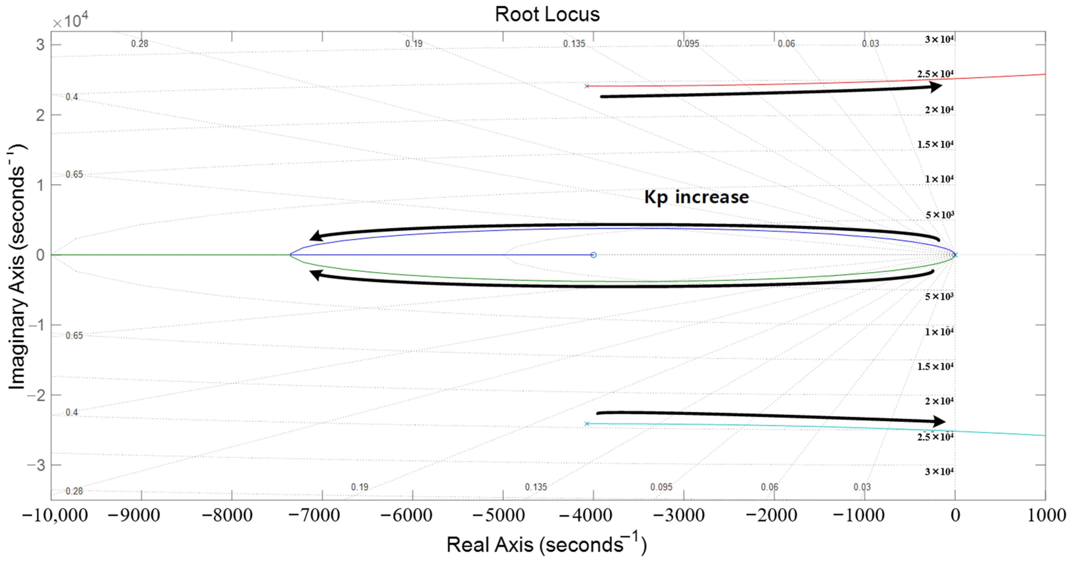
Applying Equations (4) and (5) indicates that steady state error and phase delay are expected as CFFC is applied. Using Equations (4) and (5), the stability and frequency response of the GCI current control system may be simulated and analyzed. For stability analysis of the GCI current control system with CFFC, root locus of the GCI current control system is implemented. The simulation results of the root locus implementation are shown in Figure 3.
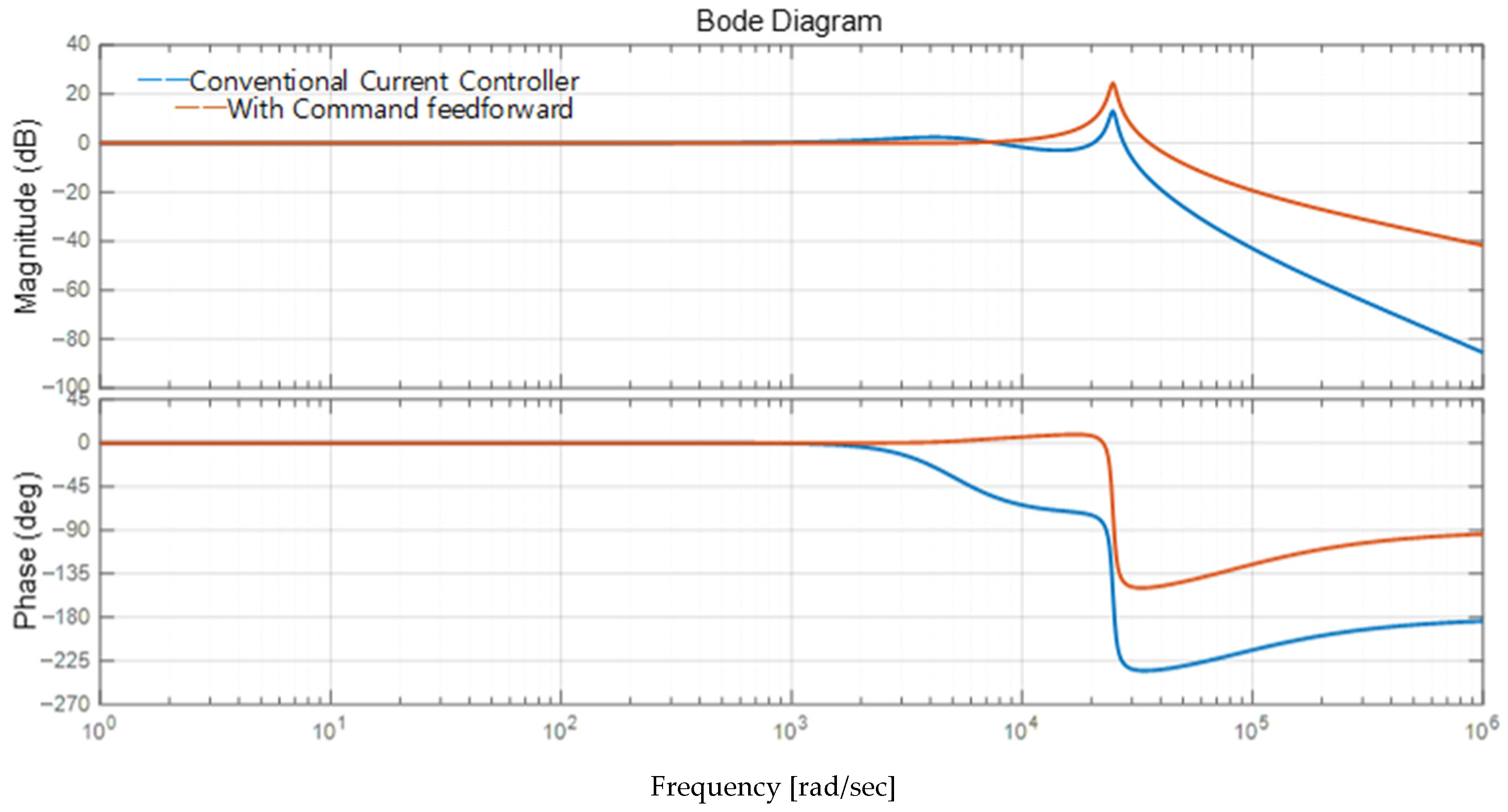
The root locus in Figure 3 shows the movement of the system’s poles with respect to variation in the proportional controller gain Kp. Applying the root locus, it is apparent that faster transient responses can be achieved, but that the GCI current control system becomes unstable as Kp increases. Accordingly, GCI current controller gains should be determined after accounting for the transient dynamic performance and stable operation of the GCI current control system using a CFFC with the root locus. Figure 4 shows the frequency response of the GCI current control system with and without the CFFC applied. Considering the magnitude of the frequency response, applying the CFFC extends the bandwidth of GCI current control system. Extending the bandwidth will likely result in faster transient dynamic performance and less steady state error. Considering the phase side of the frequency response, applying the CFFC is expected to result in less phase lagging. Based on the root locus and the frequency response, the benefits of the proposed GCI current control—improved stability and command tracking performance—are verified.
3. Disturbance Rejection Control of GCI Current Control Systems
In a GCI current control system, grid voltage is regarded as disturbance. When grid faults occur, overcurrent damages the system or its electrical circuits. One approach to solving this problem is designing a system that directly rejects any disturbances. Direct disturbance rejection control (DRC) can be achieved by feedforwarding a signal with the opposite polarity of the grid voltage to the GCI system. DRC can be implemented using grid voltage measured by a voltage sensor or by relying on a grid voltage observer. Voltage sensors are simple to implement, but their use comes at the cost of increased of system expense, complexity, and volume. For that reason, our proposed GCI current control algorithm relies on grid voltage estimates by a grid voltage observer. For a properly developed grid current observer, the controller output of the grid current observer will be identical to the grid voltage. Estimated grid voltage can be used not only to implement DRC, but also to cancel the harmonics in voltage, in the event the actual grid voltage includes harmonic components. Ultimately, total harmonic distortion (THD) can be reduced, and power quality can be improved. The proposed GCI current control system with DRC using a grid current observer is shown in Figure 5.
The main objective of the DRC is to improve the GCI’s resilience against disturbance. Dynamics stiffness—the amount of disturbance required to change an output signal—is one metric for evaluating system robustness. Systems with higher dynamics stiffness are more robust. Dynamic stiffness transfer functions of the GCI system are derived in Equations (6) (with the DRC) and (7) (without the DRC).
Figure 6 graphically illustrates the frequency response of the dynamic stiffness of the GCI system as derived from Equations (6) and (7).
As shown in Figure 6, dynamics stiffness (resilience) of the GCI current control system is significantly improved with the DRC, especially at low and medium frequency range. The DRC’s effectiveness is further verified using simulations and experiments in the subsequent sections.
4. Simulation Results and Analysis
In this section, the simulation results of conventional and the proposed GCI current control methods are presented. SRFPI current control is implemented as a conventional GCI current control method for performance comparison because SRFPI control is widely used for GCI current control applications and is a similar control system structure to the proposed GCI current control system. CFFC and DRC are also applied to the SRFPI current control method for fair performance comparison. Simulation is implemented using PLECS software and the GCI system parameters used during simulation are summarized in Table 2.
Simulation results at a normal steady state operating condition with and without the CFFC and DRC are shown in Figure 7a,b, respectively.
As seen in Figure 7a, steady state error and phase lag occur when the stationary reference frame PI current control is used for current control of a GCI system. However, the command tracking performance of the proposed GCI current control system, the stationary reference frame PI current control with the CFFC and DRC, is improved as shown in Figure 7b. The effect of the CFFC and DRC is verified through the simulation in Figure 7 and the simulation results are summarized in Table 3 below.
When the CFFC and DRC are not applied to the stationary reference frame GCI current control system, the steady state error and phase delay are shown, and the errors are larger than the results from the SRFPI grid current control system. By applying the CFFC and DRC into the stationary reference frame GCI current control system, the command tracking performance can be improved as much as the performance of the SRFPI grid current control system. Though CFFC and DRC are applied, approximately 3 degrees of phase delay appears when the proposed control method is used as shown in Table 3. At a power factor point of view, 3 degrees corresponds 0.998 power factor (cos 3°), which is 0.2% power factor error or difference and do not significantly affect power factor. Although 0.2% error in power factor appears using the proposed GCI current control method, relatively simple GCI current control system can be developed by avoiding reference frame transformation, cross-coupling issues and use of PLL which are necessary for implementation of the SRFPI grid current control system.
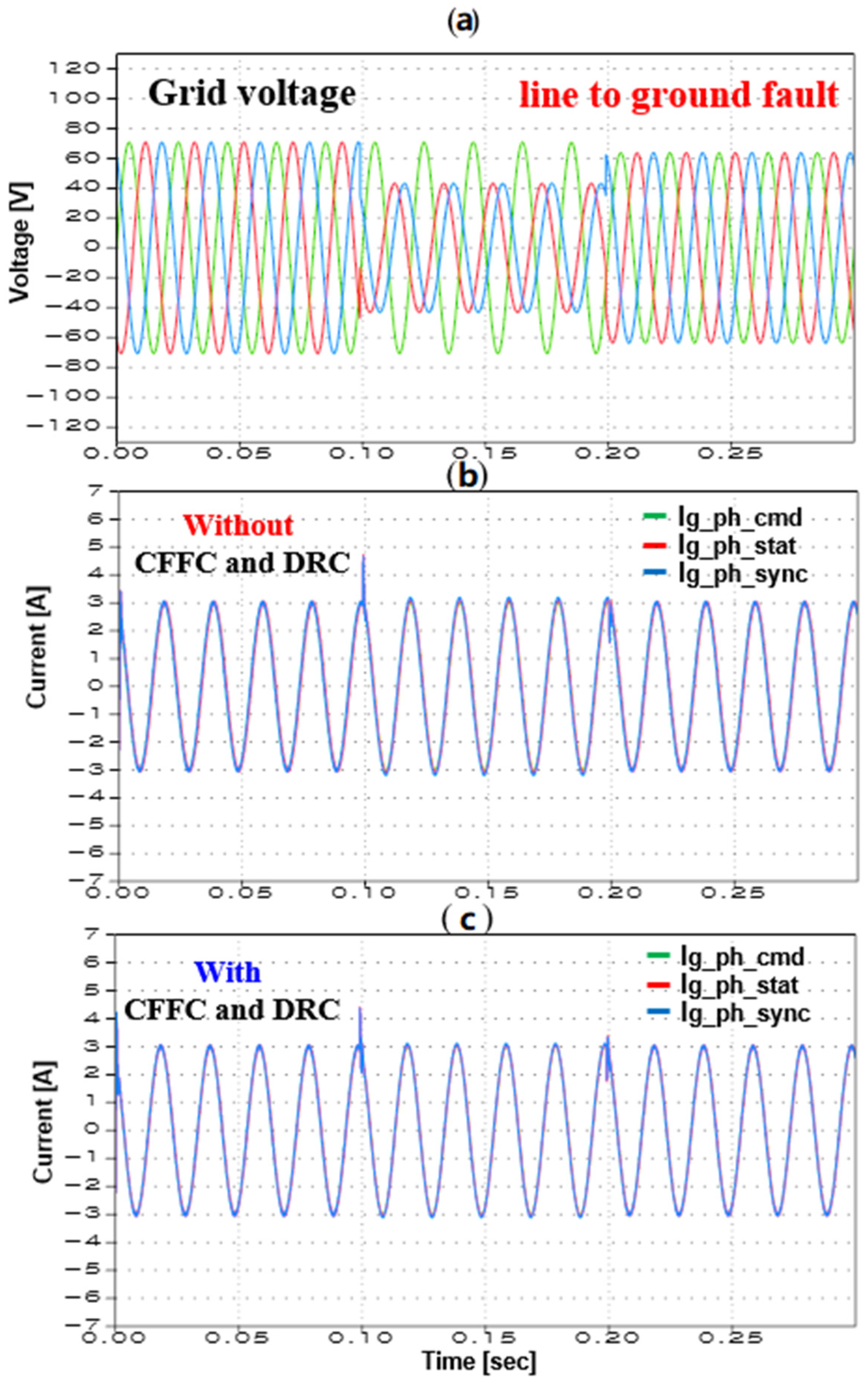
Figure 8 shows the simulation results when a line to ground fault occurs in a grid system. When grid fault occurs, the overcurrent occurs. Figure 9 shows the simulation results at the moment of grid fault in greater detail.
Figure 9a shows the current at the time of fault without CFFC and DRC, while Figure 9b shows the result with the control method applied. Table 4 compares the transient response for each current controller.
Without CFFC and DRC, 150% overcurrent occurs in the proposed method and SRFPI current controllers. With the application of CFFC and DRC, overcurrent decreased by about 10%. Because of the increased likelihood of remaining under the commercial inverter trip condition, it is more likely that linkage with the grid would have been maintained.
Figure 10 shows simulated results of estimated disturbance and grid voltage. The accuracy of grid voltage estimation determines control system performance. If grid voltage and disturbance are decoupled, or grid voltage is rejected, then effect of disturbances to the transient current is expected to be decreased. Figure 10 compares actual and estimated grid voltage and error between the two signals. As shown in the simulation results, an estimation error of disturbance of below 5% is considered expected at steady state.
The steady state and transient response of various control methods in case of a grid fault were simulated and compared. The results confirm that command tracking performance is improved by applying CFFC and DRC to the conventional control method. Their application also satisfied the overcurrent trip condition by reducing overcurrent during grid fault. In addition, the disturbance rejection is verified by applying the proposed DRC, which is presented for a backup solution when a sensor or a sensor interface board fails.
5. Experimental Results and Analysis
This section details the experimental results achieved with both conventional setups and those using the proposed control algorithm. During the experiment, the grid fault and various orders of harmonics voltage generation were emulated using the three-phase programmable AC power supply. A controller using a PLXIM’s RT box was responsible for overall system control and signal processing. RT boxes have a rapid control prototype, providing them with a distinct advantage over conventional controllers that use a DSP MCU chip. SEMIKRON’s IGBT module stack was used as an inverter, and a virtual EV’s battery was simulated using a DC power supply. This experimental setup is shown in Figure 11.
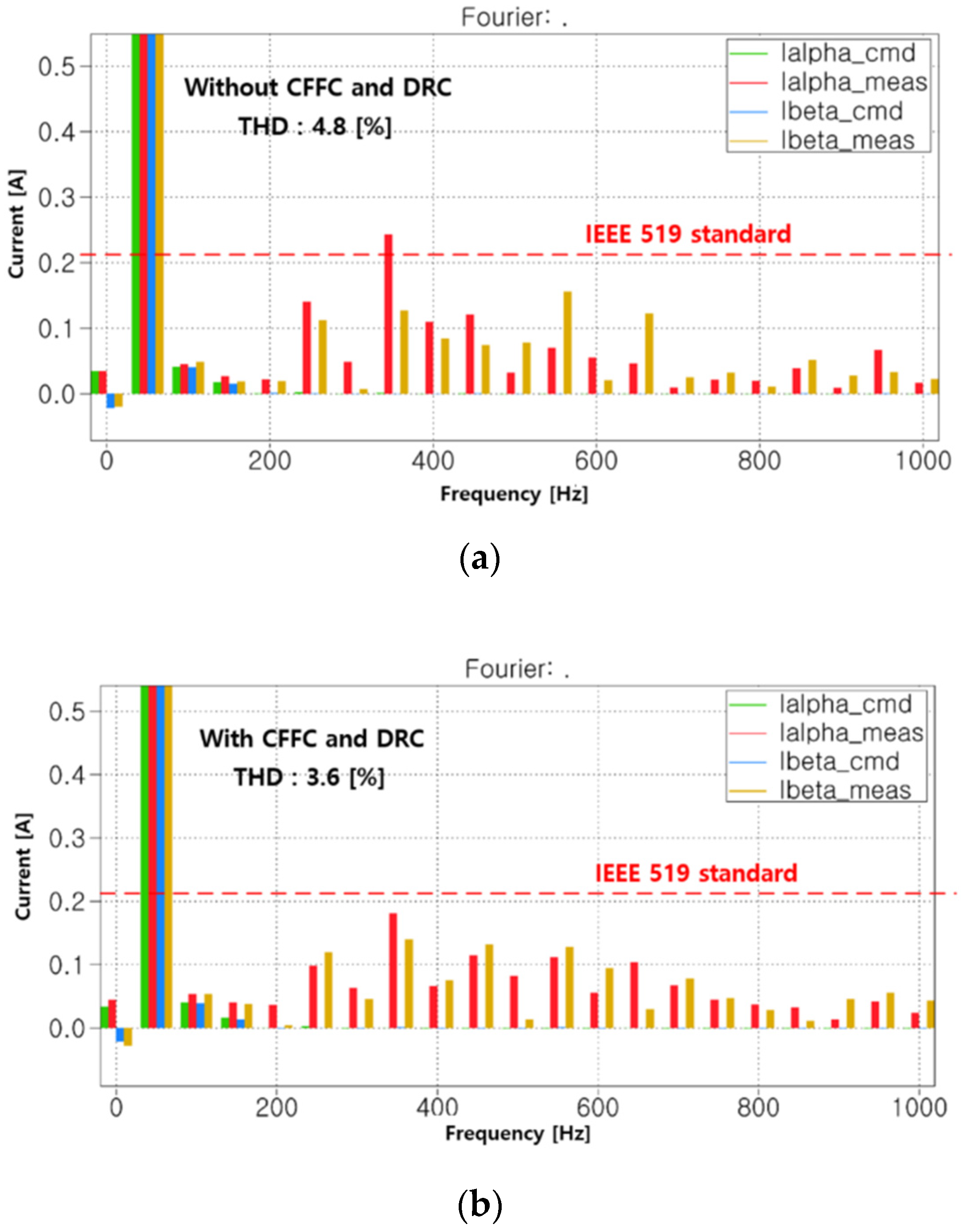
Figure 12a,b show the measured stationary reference frame grid currents and grid voltages when current control methods were used with and without CFFC and DRC. According to our experimental results, grid currents were properly controlled through with methods in the absence of grid fault. The total harmonic distortion (THD) of the experimental results shown in Figure 12 is summarized in Table 5.
According to international standards (e.g., IEEE 519), THD must be within 5% to be allowed to be connected to the distribution system. In grid normal conditions, the phase current THD before applying the proposed CFFC and DRC was approximately 4.8%. While this margin of 0.2[%] is less than the IEEE 519 standard requires, after application of our proposed method, THD dropped to 3.6%, resulting in a superior margin of approximately 1.4%.
Figure 13 shows the frequency spectrum for the grid current depicted in Figure 12. Based on these results, harmonic distortion of phase current was analyzed with reference to IEEE 519. Total harmonic distortion before application of the proposed method had a THD margin of 0.2%, which satisfies IEEE 519, but exceeded the individual harmonic distortion IEEE 519 standard of 3%. With application of the proposed CFFC and DRC method, individual harmonic distortion of less than 3% was achieved as shown in Figure 13.
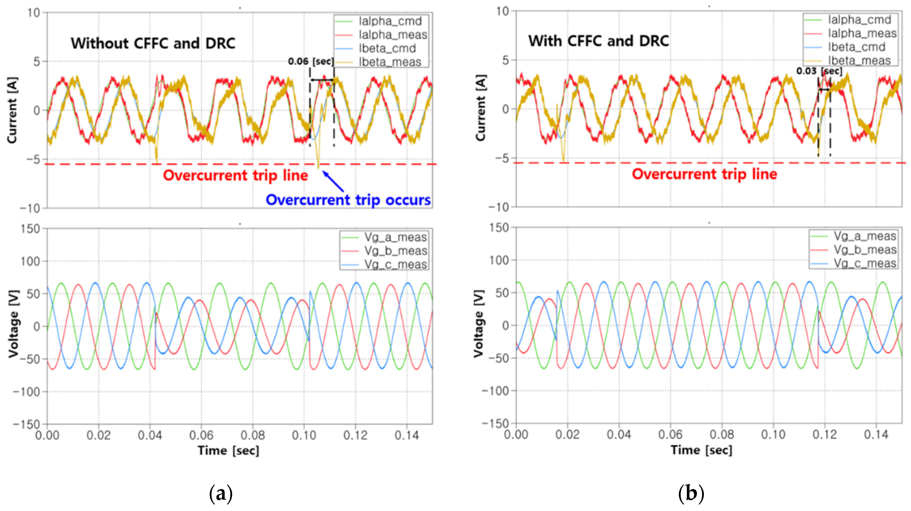
Figure 14 shows the results of current control in the circumstance of line to ground fault. While there is no current trip-related standard, the average commercial inverter has a trip standard of 200–250%. When a grid fault occurs, the peak current generated in the transient state for an inverter with a trip condition of 201% without the proposed CFFC and DRC applied is 201%. With application of the proposed CFFC and DRC, the peak current generated was reduced by 17.7% to 183.3%, leaving a margin of 16.7% before the trip condition was triggered. Moreover, when the proposed CFFC and DRC were used, transient time was reduced by about half (reduction of approximately 0.03 s). The experimental results of transient response are summarized in Table 6.
When 5th and 7th harmonics are added by nonlinear loads or machine connection to the grid, THD may exceed 5% in order to connect to a distribution system stated at IEEE 519 standard. Figure 15 shows simulated grid voltage injected with the 5th and 7th harmonics on current control. In this system, the current THD was 6.3% before application of the proposed CFFC and DRC, which exceeds the IEEE 519 standard of 1.3% and precludes it from being connected to the grid. After application of the proposed method, this THD could safely be connected to the distribution system. THD results at the distorted grid voltage conditions are summarized in Table 7.
6. Conclusions
In this paper, a three-phase GCI grid current control algorithm is developed using a relatively simple stationary reference PI controller that can be used as an alternative solution of the conventional SRFPI grid current controller. In the proposed control method, system cross-coupling complexity, reference transformation, and dependency to PLL can be avoided. For implementation of the proposed control method, two main algorithms are introduced and analyzed in this paper. First, the CFFC is used to the stationary reference PI controller to secure competition with a SRFPI controller. Using this control method, the phase delay and steady-state error of the stationary reference PI controller are reduced. Second, in order to compensate for the weakness of the PI controller’s poor disturbance rejection performance, a disturbance rejection control is applied using a grid current observer. When grid fault occurs, peak current is reduced when the proposed current control algorithm is used. Additionally, power quality improvements are verified by comparing the THD of the phase current when grid voltage is distorted by external conditions. The three-phase GCI grid current control performance improvement and comparative analysis are verified through simulation and experimentation in this paper.
Author Contributions
H.J. implemented the simulations and experiments discussed in this paper. J.S.L. proposed the control algorithms. J.H.C. advised in setting up the experimental bench and writing. All authors have read and agreed to the published version of the manuscript.
Funding
This research is supported by Korea Electric Power Corporation through the Korea Electrical Engineering & Science Research Institute [grant number: R18XA04]. This research was supported by Base Science Research Program through the National Research Foundation of Korea (NRF), funded by the Ministry of Education (2020R1C 1C 1013260).
Conflicts of Interest
The authors declare no conflict of interest.
References
- Geng, Y.; Qi, Y.; Zheng, P.; Gao, F.; Gao, X. A virtual RLC active damping method for LCL type grid connected inverters. J. Power Electron. 2018, 18, 1555–1566. [Google Scholar]
- Fu, Z.; Feng, Z.; Chen, X.; Zheng, X.; Yin, J. Frequency synchronization of three phase grid connected inverters controlled as current supplies. J. Power Electron. 2018, 18, 1347–1356. [Google Scholar]
- Lee, J.; Cho, Y.; Kim, H.; Jung, J. Design methodology of passive dampled LCL filter using current controller for grid connected three phase voltage source inverters. J. Power Electron. 2018, 18, 1178–1189. [Google Scholar]
- Fan, Y.; Xue, Z.; Han, X. Bi-directional converting technique for vehicle to grid. Proc. ICEMS 2011, 1–5. [Google Scholar] [CrossRef]
- Shin, C.J.; Lee, J.Y. An electrolytic capacitor-less bi-directional EV on-board charger using harmonic modulation technique. IEEE Trans. Power Electron. 2014, 29, 5195–5203. [Google Scholar] [CrossRef]
- Liu, H.; Zhou, J.; Wang, W.; Xu, D. Droop control scheme of a three phase inverter for grid voltage unbalance compensation. J. Power Electron. 2018, 18, 1245–1254. [Google Scholar]
- Lai, N.; Kim, K. An Improved Current Control Strategy for a Grid-Connected Inverter under Distorted Grid Conditions. Energies 2016, 9, 190. [Google Scholar] [CrossRef] [Green Version]
- Dhen, D.; Zhang, J.; Qian, Z. An Improved Repetitive Control Scheme for Grid- Connected Inverter With Frequency-Adaptive Capability. IEEE Trans Ind. Electron. 2012, 60, 814–823. [Google Scholar]
- Lee, C.; Choi, J. Compensation strategy to eliminate the effect of current measurement offsets in grid-connected inverters. J. Power Electron. 2014, 14, 383–391. [Google Scholar] [CrossRef] [Green Version]
- Chadorkar, M.; Divan, D.; Adapa, R. Control of parallel connected inverters in standalone AC supply systems. IEEE Trans. Ind. Appl. 1993, 29, 136–143. [Google Scholar] [CrossRef]
- Doki, S.; Okuma, S. Fast torque control system for PMSM based on model predictive control considering overmodulation region. IEEE ECCE Asia 2010, 1403–1406. [Google Scholar] [CrossRef]
- Ryan, M.J.; Brumsickle, W.E.; Lorenz, R.D. Control topology options for single phase UPS inverters. IEEE Trans. Ind. Appl. 1997, 33, 493–501. [Google Scholar] [CrossRef] [Green Version]
- Abdel-Rahim, N.M.; Quaicoe, J.E. Analysis and design of a multiple feedback loop control strategy for single phase voltage source UPS inverter. IEEE Trans. Power Electron. 1996, 11, 532–541. [Google Scholar] [CrossRef]
- Jeong, H.; Lee, J.S. A stationary reference frame current control algorithm for improvement of transient dynamics of a single phase grid connected inverter. Electronics 2020, 9, 722. [Google Scholar] [CrossRef]
- Zmood, N.; Holmes, D. Stationary frame current regulation of PWM inverters with zero steady state error. IEEE Trans. Power Electron. 2003, 18, 814–822. [Google Scholar] [CrossRef]
- Ahmed, K.; Massoud, A.; Finney, S.; Williams, B. A modified stationary reference frame based predictive current control with zero steady state error for LCL coupled inverter based distributed generation systems. IEEE Trans. Ind. Electron. 2011, 58, 1359–1370. [Google Scholar] [CrossRef]
- ABB Industry Power Electronics. Frequency Converters for Speed Control of 0.55 to 4.0 kW Squirrel Cage Motors (ACS200) User’s Manual; EN 5805765-7; ABB Industry Power Electronics: New Berlin, WI, USA, 1994. [Google Scholar]
- Parker Hannifin Ltd. 690+ Series AC Drive (Frame K) Product Manual; HA465746U001, Issue 3; Parker SSD Drives, a division of Parker Hannifin Ltd.: Littlehampton, UK, 2010. [Google Scholar]
- Chen, W.H.; Ballance, D.J.; Gawthrop, P.J.; Member, S.; Reilly, J.O.; Member, S. A Nonlinear Disturbance Observer for Robotic Manipulators. IEEE Trans. Ind. Electron. 2000, 47, 932–938. [Google Scholar] [CrossRef] [Green Version]
- Sariyildiz, E.; Ohnishi, K. Stability and robustness of disturbance observer-based motion control systems. IEEE Trans. Ind. Electron. 2015, 62, 414–422. [Google Scholar] [CrossRef]
- Cheng, X.; Tu, X.; Zhou, Y.; Zhou, R. Active disturbance rejection of multi-joint industrial robots based in dynamic feedforward. Electronics 2019, 8, 591. [Google Scholar] [CrossRef] [Green Version]
- Han, J.; Wang, H.; Jiao, G.; Cui, L.; Wang, Y. Research on active disturbance rejection control technology of electromechanical actuators. Electronics 2018, 7, 174. [Google Scholar] [CrossRef] [Green Version]
- Peng, Y.; He, Y.; Hang, L. Low pass active grid impedance cancellation in grid connected inverters with LCL filter. Appl. Sci. 2019, 9, 4636. [Google Scholar] [CrossRef] [Green Version]
Figure 1.
Graphical representation multiple distributed generation (DG) systems interfaced with the main grid [23].
Figure 1.
Graphical representation multiple distributed generation (DG) systems interfaced with the main grid [23].

Figure 2.
Block diagram of a GCI current control system with command feedforward control (CFFC).

Figure 3.
Root locus of the GCI current control system applying the CFF control.

Figure 4.
Frequency response of the GCI current control system with and without the CFFC.

Figure 5.
System block diagram with a grid current observer for disturbance rejection in a GCI current control system.
Figure 5.
System block diagram with a grid current observer for disturbance rejection in a GCI current control system.

Figure 6.
Dynamic stiffness of the GCI current control system with and without the DRC.

Figure 7.
Simulation results of GCI current control system for the proposed stationary reference frame proportional-integral (PI) current control and synchronous reference PI (SRFPI) current control (a) without and (b) with the CFFC and DRC.
Figure 7.
Simulation results of GCI current control system for the proposed stationary reference frame proportional-integral (PI) current control and synchronous reference PI (SRFPI) current control (a) without and (b) with the CFFC and DRC.

Figure 8.
Simulation results of GCI system phase current (a) when line-to-ground grid fault occurs, (b) without and (c) with the CFFC and DRC.
Figure 8.
Simulation results of GCI system phase current (a) when line-to-ground grid fault occurs, (b) without and (c) with the CFFC and DRC.

Figure 9.
Simulation results of the output currents (a) without and (b) with the CFFC and DRC.

Figure 10.
Simulation results of actual grid voltage and grid voltage using an observer.

Figure 11.
GCI experimental set-up for EV’s application.

Figure 12.
When normal grid condition, experimental results of proposed method a stationary reference frame grid currents and grid voltages (a) without CFFC and DRC and (b) with CFFC and DRC.
Figure 12.
When normal grid condition, experimental results of proposed method a stationary reference frame grid currents and grid voltages (a) without CFFC and DRC and (b) with CFFC and DRC.

Figure 13.
Under normal grid conditions, the frequency spectrums of the stationary reference frame grid currents (a) without CFFC and DRC and (b) with CFFC and DRC.
Figure 13.
Under normal grid conditions, the frequency spectrums of the stationary reference frame grid currents (a) without CFFC and DRC and (b) with CFFC and DRC.

Figure 14.
When line-to-ground fault occurs, experimental results of the stationary reference frame grid currents and abc reference frame grid voltages (a) without CFFC and DRC and (b) with CFFC and DRC.
Figure 14.
When line-to-ground fault occurs, experimental results of the stationary reference frame grid currents and abc reference frame grid voltages (a) without CFFC and DRC and (b) with CFFC and DRC.

Figure 15.
When 5th, 7th harmonics are injected to the grid, experimental results of the stationary reference frame grid currents and grid voltages (a) without CFFC and DRC and (b) with CFFC and DRC.
Figure 15.
When 5th, 7th harmonics are injected to the grid, experimental results of the stationary reference frame grid currents and grid voltages (a) without CFFC and DRC and (b) with CFFC and DRC.


Table 1.
Definition of variables in a grid-connected inverter (GCI) current control system.
| System Variables and Definition | System Variables and Definition | ||
|---|---|---|---|
| L1 | Inverter side LCL filter inductance | ig | Grid current |
| L2 | Grid side LCL filter inductance | vg | Grid voltage |
| Cf | LCL filter capacitance | vcf | Voltage across a filter capacitor |
| Rd | Damping resistance | vi | Output voltage from an inverter |
Table 2.
GCI system and controller parameters.
| Parameters | Value | Parameter | Value |
|---|---|---|---|
| Grid voltage (Vg) | 50 [VAC] | Inverter side inductor (L1) | 1.5 [mH] |
| Frequency | 50 [Hz] | Filter capacitor (Cf) | 2.75 [μF] |
| DC link voltage | 180 [VDC] | Damping resistor (Rd) | 4.9 [Ω] |
| Switching frequency | 10 [kHz] | Grid side inductor (L2) | 1 [mH] |
Table 3.
Simulation results of GCI system phase current without and with the CFFC and disturbance rejection control (DRC).
Table 3.
Simulation results of GCI system phase current without and with the CFFC and disturbance rejection control (DRC).
| Control Algorithm | Steady State Error [%] | Phase Lag [Degree] | ||
|---|---|---|---|---|
| Without CFFC and DRC | With CFFC and DRC | Without CFFC and DRC | With CFFC and DRC | |
| Proposed method | 4.9 | −0.003 | 23.67 | 3.2 |
| SRFPI | 0.8 | 0 | 0 | 0 |
Table 4.
Simulation results of GCI system phase current without and with the CFFC and DRC.
| Control Algorithm | Peak Current | ||
|---|---|---|---|
| Without CFFC and DRC | With CFFC and DRC | Reduction Ratio | |
| Proposed method | 157.67 [%]/4.73 [A] | 147 [%]/4.41 [A] | 10.67 [%]/0.32 [A] |
| SRFPI | 155.67 [%]/4.67 [A] | 146 [%]/4.38 [A] | 9.67 [%]/0.29 [A] |
Table 5.
Experiment results of GCI system phase current total harmonic distortion (THD) in normal grid condition.
Table 5.
Experiment results of GCI system phase current total harmonic distortion (THD) in normal grid condition.
| Control Algorithm | Total Harmonic Distortion (THD) | ||
|---|---|---|---|
| Without CFFC and DRC | With CFFC and DRC | Reduction Ratio | |
| Proposed method | 4.8 [%] | 3.6 [%] | 1.2 [%] |
Table 6.
Experiment results of GCI system phase current THD when line-to-ground fault occurs.
| Transient Response | Transient Response Characteristics | ||
|---|---|---|---|
| Without CFFC and DRC | With CFFC and DRC | Reduction Ratio | |
| Peak current | 6.03 [A]/201 [%] | 5.5 [A]/183.3 [%] | 0.48 [A]/17.7 [%] |
| Transient time | 0.06 [s] | 0.03 [s] | 0.03 [s] |
Table 7.
Experiment results of GCI system phase current THD when 5th, 7th harmonics injected grid condition.
Table 7.
Experiment results of GCI system phase current THD when 5th, 7th harmonics injected grid condition.
| Total Harmonic Distortion (THD) | ||
|---|---|---|
| Without CFFC and DRC | With CFFC and DRC | Reduction Ratio |
| 6.3 [%] | 4.8 [%] | 1.5 [%] |
Publisher’s Note: MDPI stays neutral with regard to jurisdictional claims in published maps and institutional affiliations. |
© 2020 by the authors. Licensee MDPI, Basel, Switzerland. This article is an open access article distributed under the terms and conditions of the Creative Commons Attribution (CC BY) license (http://creativecommons.org/licenses/by/4.0/).
Share and Cite
MDPI and ACS Style
Jeong, H.; Choi, J.H.; Lee, J.S. A Current Control Algorithm to Improve Command Tracking Performance and Resilience of a Grid-Connected Inverter. Appl. Sci. 2020, 10, 8642. https://doi.org/10.3390/app10238642
AMA Style
Jeong H, Choi JH, Lee JS. A Current Control Algorithm to Improve Command Tracking Performance and Resilience of a Grid-Connected Inverter. Applied Sciences. 2020; 10(23):8642. https://doi.org/10.3390/app10238642
Chicago/Turabian StyleJeong, Horyeong, Jong Hyuk Choi, and Jae Suk Lee. 2020. "A Current Control Algorithm to Improve Command Tracking Performance and Resilience of a Grid-Connected Inverter" Applied Sciences 10, no. 23: 8642. https://doi.org/10.3390/app10238642
Note that from the first issue of 2016, this journal uses article numbers instead of page numbers. See further details here.