Observation of an Electromagnetically Induced Grating in Cold 85Rb Atoms


1
State Key Laboratory of Quantum Optics and Quantum Optics Devices, Institute of Laser Spectroscopy, Shanxi University, 92 Wucheng Road, Taiyuan 030006, China
2
Collaborative Innovation Center of Extreme Optics, Shanxi University, 92 Wucheng Road, Taiyuan 030006, China
*
Authors to whom correspondence should be addressed.
Appl. Sci. 2020, 10(17), 5740; https://doi.org/10.3390/app10175740
Submission received: 4 August 2020
/
Revised: 15 August 2020
/
Accepted: 17 August 2020
/
Published: 19 August 2020
(This article belongs to the Section Optics and Lasers)
Abstract
:Electromagnetically induced grating (EIG) is extensively investigated as an artificial periodic structure in recent years owed to its simple reconfiguration and flexible adjustability. We report the experimental observation of EIG in cold rubidium atoms. The coupling and probe lasers are corresponding to the and transitions of a V-type electromagnetically induced transparency (EIT) configuration, respectively. A clear spatial intensity distribution of the probe laser with distinguished third-order diffraction pattern is recorded to character the EIG. The influence of the pertinent experimental parameters, such as coupling laser intensity and two-photon detuning on the diffraction pattern is investigated in detail. This is the first observation in visual form of the EIG in cold rubidium atoms. These results may potentially provide a nondestructive method to image cold atoms and pave the way for investigating non-Hermitian physics and the control of light dynamics.
1. Introduction
The success in the production of cold atoms opens up many interesting research fields, among which the electromagnetically induced transparency (EIT) [1,2,3] implemented in cold atomic systems has been extensively investigated in recent years [4,5]. EIT is a kind of quantum coherence effect that makes the absorbing medium transparent to the weak probe field. While studying EIT generally focuses on the traveling wave of the laser field, more recently there has been considerable interest in electromagnetically induced grating (EIG), which replaces traveling wave fields of EIT with strong coupling standing-wave fields [6,7,8]. By adopting this method, the dispersion and absorption of the probe laser beam will be modulated spatially in an atomic medium. The EIG configuration is easier to tune and construct than the traditional grating, so it can directly control the properties of light propagation. EIG has lots of potential applications in the area of all-optical communications, such as optical switching [9], optical diodes [10], optical bistability [11], beam splitter [12], and coherently induced photonic band gaps [13].
Up to now, atoms are still the most appropriate medium to achieve EIG, and several experimental realizations of EIG have been done in thermal atom medium. In particular, the diffraction pattern of the probe laser propagated through the EIG was attracted more attention [14,15]. The research on the grating controllability, such as structural parameters and the diffraction characteristics, was studied in a rubidium vapor cell [16,17]. Moreover, the EIG was applied to illustrate the electromagnetically induced Talbot effect in a thermal vapor [18,19]. Recently, the EIG has been developed in multi-dimensional in thermal atomic system and shows more possibilities in simulation of non-Hermitian physics [20,21,22], and the research of the reconfigurable photonic graphene based on EIG will open the way for future experimental exploration of topological photonics [23,24].
Compared with the atoms in thermal vapor, the EIG in cold atoms gives more potential for in where the Doppler effect is reduced to negligible. The EIG spectra were first realized experimentally in the cold sodium atoms with a three-level system, which exhibits background-free Lorentzian signal profiles [7]. In addition, by an optical-pumping-transferred ground-state, the transient Bragg diffraction was also observed in cold cesium atoms at the same year [25]. To our best knowledge, there are no more experimental reports on the EIG in cold ensembles. In addition, the two experiments above are focusing on studying the spectrum of the EIG, the research in the visual form of the EIG in cold atoms receives no report. Compared with the spectrum, the visual research can not only observe the diffraction grating of EIG more vividly, but also can intuitively obtain more information about the characteristic parameters under different experimental conditions. In such visual systems, we can get an optimal configuration for desired applications by controlling different experimental parameters [15].
In this paper, a tunable EIG is realized in a three-level V-type system of Rb cold atoms. In cold atomic medium, the two coupling lasers interfere with each other and generate a strong standing-wave field. Then, a weak probe laser counter-propagated through the cold atoms, and the diffraction pattern of the weak probe field was recorded in a visual form to real-time monitor the EIG. We find that the diffraction characters can be flexibility controlled through the two-photon detuning and the coupling laser power. These results will further motivate the non-Hermitian physics simulation and provide a nondestructive method to image cold atoms.
2. Experiment Setup
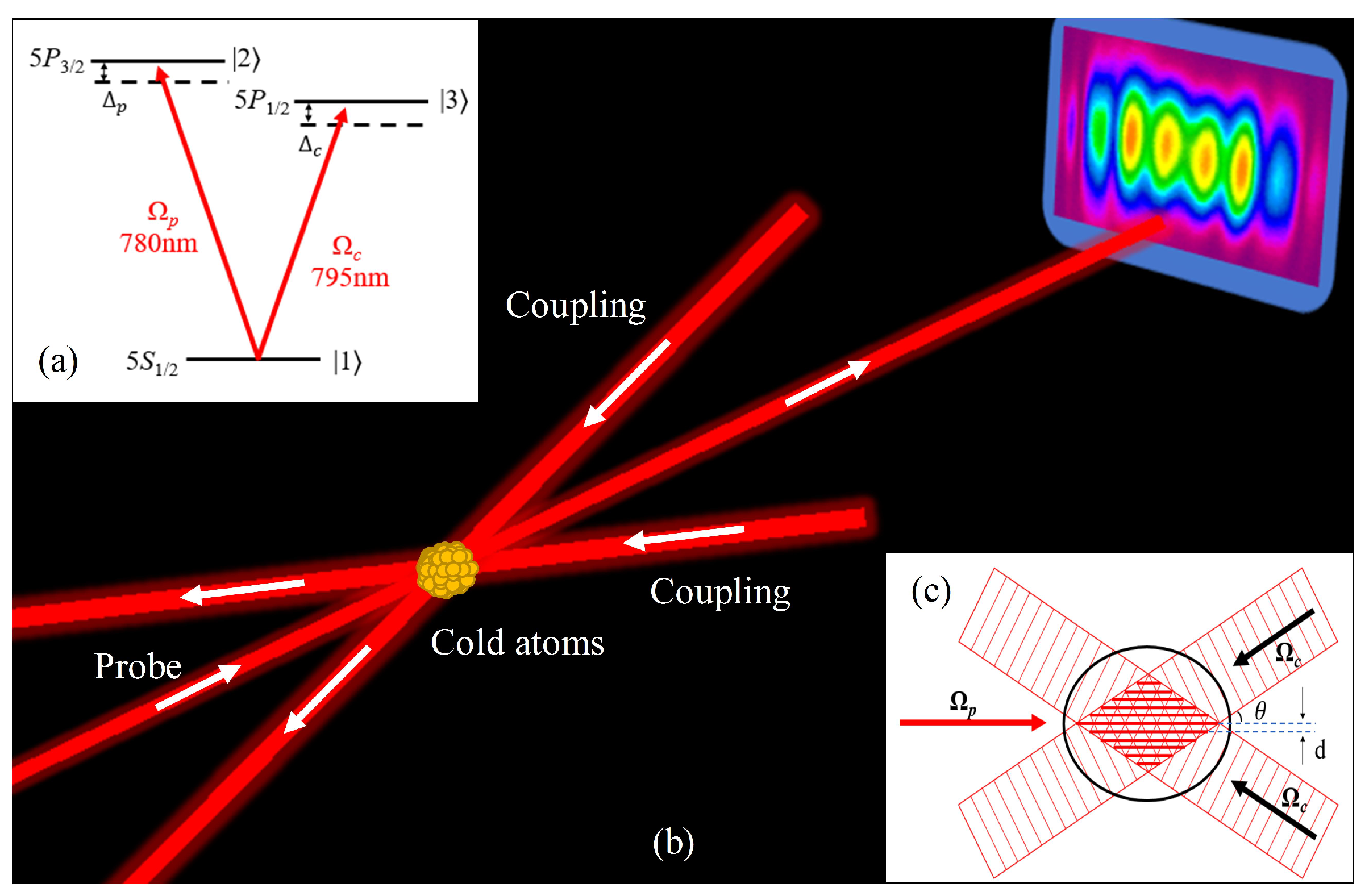
The cold Rb atoms are obtained by a traditional magneto-optical trap (MOT) method. The cooling and repumping lasers are corresponding to the hyperfine transitions of and , respectively. The atoms with a Gaussian distribution, temperature of T ∼ 100 K, radius of ∼ 0.6 mm and peak atomic density of N ∼ 10 cm, are populated in state. A V-type energy level configuration is employed to achieve the EIG as shown in Figure 1a. The probe laser operating around the D2 line of rubidium (780 nm) excites the atoms from ground state to excited state. While the coupling laser operating around the D1 line of rubidium (795 nm) pumps the atoms to a excited state.
The scheme to construct EIG depends on the periodic modulation of the refractive index in the cold atom ensemble. The beams spatial configuration of this experiment is shown in Figure 1b. The cooling and repumping lasers for the MOT are omitted for a more intuitive illustration. Three laser beams are incident into the MOT with Rb cold atoms. The coupling and probe laser beams corresponding to 795 nm and 780 nm are provided by two external cavity diode lasers (DL pro, Toptica, Munich, Germany). The saturation absorption spectroscopy (SAS) method is used to lock the frequency of these two lasers. In addition, the laser frequencies are monitored by a wavelength meter (WS-7, HighFinesse, Tubingen, Germany). We firstly use an anamorphic prism pair for shaping the coupling laser into an elliptical profile to expand the effective area of the standing-wave field. This shaped laser is then split by a beam splitter into two lasers. Then, the two lasers with a small angle about 0.13 degree are recombined together in the center of the cold atoms ensemble. Figure 1c is a standing-wave field perpendicular to the direction of laser beams, generated by the two interference crossed coupling lasers. The spatial period of the stanging-wave along the x-direction perpendicular to the propagation direction z is m, where is the wavelength of coupling laser. The probe laser, whose frequency can be precisely detuned by a double-pass configuration based on an acousto-optics modulator (AOM), is counter-propagating with the standing-wave coupling lasers in the medium and will be diffracted into high-order patterns. By using a charge-coupled device (CCD), the intensity and spatial distributions of the probe laser propagated through the EIG will be observed in real time.
3. Results and Discussion
We consider a cold Rb atomic medium with a length of L in the V-type system shown in Figure 1a, where and are the Rabi frequencies of the weak probe field and strong coupling field, respectively. By using the density matrix and perturbation theory [26], the susceptibility of probe field is given by [1]
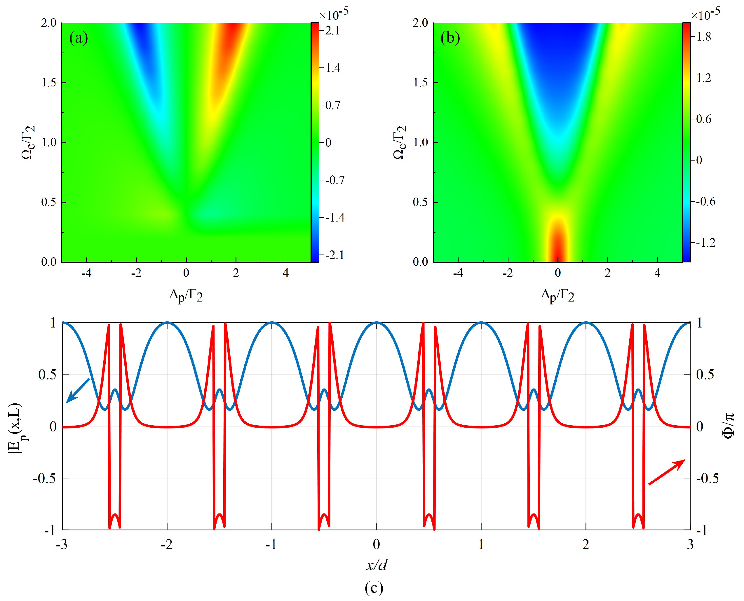
where N is the atomic density, denotes the transition dipole momentum between the stats and , is the permittivity of free space, and is the decay rate from the corresponding level. Here, and are the probe and coupling frequency detunings, respectively. In addition, are the frequency differences between the states and . We assume the standing-wave field has a sinusoidal profile as . Considering , we simulate the dispersion () and absorption () of the probe field with the probe laser frequency detuning and coupling laser Rabi frequency, which are shown in Figure 2a,b. From the simulation, we find that not only the probe laser detuning, but also the coupling laser Rabi frequency can influence the dispersion and absorption of the probe field. It is observed that the width of EIT windows is proportional to the Rabi frequency of the coupling field.
By using the Maxwell equation, the propagation dynamics of the probe field in the ensemble can be calculated analytically and the transmission at the output probe surface at can be written as
where is the input probe profile and . When , there only has the amplitude modulation (, ), which results in a periodic amplitude modulation on the probe profile. A phase modulation (, ) will appear in the output profile if we detune the probe field frequency away from the resonance transition. Figure 2c shows a typical hybrid grating when and , the blue and the red curves are the transmission function and the corresponding phase , respectively. It can be found that there exists a rapid phase change of the probe field at nodes, which will not appear in an amplitude grating [27].
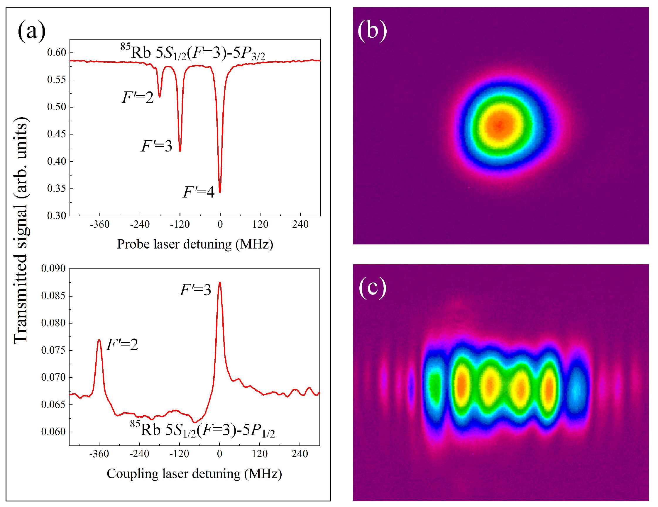
The experimental EIT configuration was observed and confirmed by a photodiode detector to detect the absorption of the probe laser. Figure 3a shows the saturation absorption spectroscopy of probe laser (above) and the absorption spectrum of probe laser in the presence of a coupling laser of the V-type system (below) in Rb cold atoms. The SAS without Doppler background is obtained by scanning the probe laser frequency near the hyperfine transition. We can get all three hyperfine transitions . Since the absorption is much more prominent, we choose this transition for the following experiment—while by locking the probe laser frequency on the transition of and scanning the frequency of coupling laser, we obtained the absorption spectrum of probe laser in the presence of coupling laser. With the probe laser (with its frequency far from the resonance) launched into the MOT and the coupling fields blocked, we observed the corresponding Gaussian profile in the CCD, which is illustrated in Figure 3b. When we lock the coupling laser frequency on the transition and fix the probe laser frequency near the transition of , a distinct diffraction pattern is obtained as shown in Figure 3c. Here, the powers of the coupling and probe lasers are about 16 W and 1 W, and the frequency detunings are = 0 and = 10 MHz, respectively. The density of the cold atoms in MOT is the Gaussian distribution, which is different from the randomly distribution of atomic density in a thermal vapor cell, and the cold atoms are more concentrated in the center of the MOT. In addition to being diffracted, the probe laser also has a strong absorption at the center of the cold atom ensemble. Therefore, the diffraction intensity at the corresponding position will appear relatively weak affected by the distribution of atomic density. This is significantly different from the diffraction patterns in thermal atoms. However, the observation of the diffraction pattern is more stable compared with the thermal atomic vapor case owing to the low-fluctuation of cold atom density.
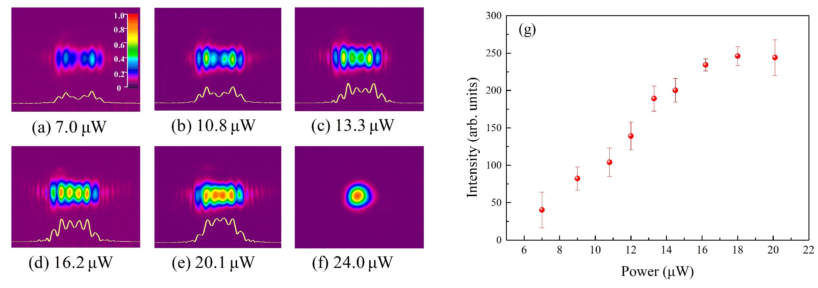
According to Equation (1), some system parameters can influence the susceptibility of this system, such as the density of cold atoms, the coupling laser power, and the two-photon detuning. This means that the diffraction pattern can be controlled by these tunable parameters. In some experiments related to cold atoms, the atomic density mainly depends on the power of the lasers used in MOT configuration. We keep the initial density of cold atoms for about cm throughout the experiment. The grating constant is determined by the angle of the two coupling lasers. When the angle is too small, the diffraction phenomenon is hard to be detected due to the less diffraction orders, while, when the angle is too large, the diffraction patterns become dense and less distinguishable. The crossing angel of two coupling lasers is about 0.13 degree in this work, which resulted in a grating constant of 175 m and a better diffraction pattern. Figure 4a–f are a series of diffraction patterns obtained by changing the coupling laser power, and the yellow curves are the corresponding spatial intensity distributions. With a coupling laser power of 7 W, the diffraction of probe laser begins to appear. Then, the diffraction patterns gradually become distinct with the increasing power, which are shown from Figure 4b,c. The most recognizable pattern is observed when the power attains to 16.2 W as illustrated in Figure 4d. With the increase of the coupling intensity, the nonlinear enhancement of the EIT effect greatly promotes the formation of the distinct diffraction patterns [6]. Further increasing the power, the diffraction intensities of each order have a corresponding growth, but the resolution becomes worse. With a large coupling laser power of 24 W, the Gaussian profile of the probe laser reappears on the CCD. The reason for this case is that, with such a strong coupling laser field, the balance of the MOT configuration was broken, partial atoms escaped from the MOT. The cold atom medium is disturbed and its Gaussian distribution is destroyed when the power exceeds this limit value. The above phenomenon of Figure 4d–f is different from the experiment of EIG in thermal atoms. In thermal atoms related experiments, the diffraction intensity increases with the increasing of coupling laser power like in cold atoms. However, continuing to increase the coupling laser power, the diffraction intensity will reach a maximum value and then decrease. The absorption of the probe field is suppressed by a strong coupling field and the grating transparent will be rendered [16]. In order to illustrate the diffraction intensity variation trend specifically, we have measured the second-order diffraction intensity with different coupling laser powers, as shown in Figure 4g. The red dots and error bars are the average results and standard deviation of three experiments, respectively. As a result, the diffraction intensity is found to increase with the increasing power, and it comes into saturation at about 16 W. That is to say, a strong intensity of the coupling laser makes more photons pumping the atoms from the lower energy level, which induces a nonlinear effect. However, as mentioned above, when the power of the coupling laser continue increases, more trapped atoms will escape from the MOT, thus the EIG starts to weaken and then disappears.
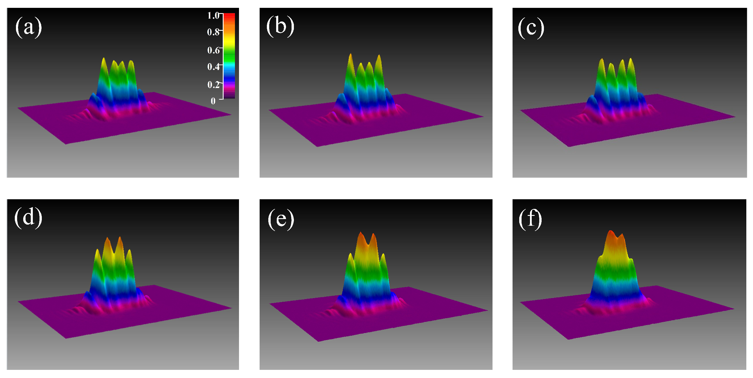
From Equation (2), we find that the formed hybrid grating will influence the transmission function and the corresponding phase of the output probe surface, in addition to the output diffraction patterns. For more detailed research of this effect, we have studied the influence of the two-photon detuning on the diffraction patterns. The diffraction pattern of probe laser will be changed with different two-photon detunings , and the observed three-dimensional diffraction patterns are shown in Figure 5; here, we keep . The powers of the probe and coupling lasers are 1 W and 16 W, respectively. Figure 5a shows a pure amplitude grating when the two-photon detuning is zero. When the coupling laser frequency resonances on hyperfine transition, while the probe laser frequency is gradually tuned away from hyperfine transition, a phase modulation is introduced in this system and the pure amplitude grating becomes a hybrid grating. The diffraction intensity will be enhanced in a small two-photon detuning window, as shown from Figure 5b–f. The most distinguishing diffraction pattern that appears in our experiment is just near 10 MHz two-photon detuning, which is shown in Figure 5c. The experimental result and theory are in qualitative agreement, and a narrow frequency window of about 20 MHz exists for a better diffraction effect. This indicates that both amplitude and phase modulations are introduced to guide the probe laser in the non-resonant case, and the diffraction pattern will have a high resolution in hybrid grating compared with the pure amplitude grating. When the two-photon detuning exceeds this frequency range, the diffraction patterns will gradually fade, seen from Figure 5f.
4. Conclusions
In conclusion, we have experimentally realized an EIG in a V-type coherent Rb cold ensemble. Here, the cold atomic medium is regarded as a periodic structure with periodically modulated refractive index. The diffraction patterns with different coupling laser powers and two-photon detunings are investigated in detail. Affected by the unique characteristic of the cold atom trapped in MOT, our experimental phenomenon has some different with the previous experiments in thermal vapor. It is mainly reflected in the low diffraction intensity at the central position of the atoms ensemble, and the vanishing of the EIG effect caused by the escape of the atoms when the coupling laser intensity is too high. However, our result is much more stable than in thermal vapor and has great potential for weak light field detection. We firmly believe that our visual work will promote the research in the field of artificial and periodically modulated photonic devices.
Author Contributions
Conceptualization, H.Z. and J.Y.; investigation, H.Z. and S.D.; software, H.Z.; validation, H.Z., J.Y., and L.W.; formal analysis, H.Z., S.D., and C.W.; Writing—original draft, H.Z.; writing—review and editing, J.Y., C.W., and L.W.; project administration, J.Y. and L.W.; and funding acquisition, J.Y. and L.W. All authors have read and agreed to the published version of the manuscript.
Funding
This work was supported by the National Key R&D Program of China (No. 2017YFA0304203), the National Science Foundation of China (Nos. 61875112, 61705122, and 91736209), the Program for Sanjin Scholars of Shanxi Province, Key Research and Development Program of Shanxi Province for International Cooperation (No. 201803D421034), and the Fund for Shanxi “1331 Project” Key Subjects Construction.
Conflicts of Interest
The authors declare no conflict of interest.
References
- Fleischhauer, M.; Imamoglu, A.; Marangos, J.P. Electromagnetically induced transparency: Optics in coherent media. Rev. Mod. Phys. 2005, 77, 633–673. [Google Scholar] [CrossRef] [Green Version]
- Wu, Y.; Yang, X. Electromagnetically induced transparency in V-, Λ-, and cascade-type schemes beyond steady state analysis. Phys. Rev. A 2005, 71, 053806. [Google Scholar] [CrossRef]
- Qin, M.; Pan, C.; Chen, Y.; Ma, Q.; Liu, S.; Wu, E.; Wu, B. Electromagnetically Induced Transparency in All-Dielectric U-Shaped Silicon Metamaterials. Appl. Sci. 2018, 8, 1799. [Google Scholar] [CrossRef] [Green Version]
- Hao, L.; Jiao, Y.; Xue, Y.; Han, X.; Bai, S.; Zhao, J.; Raithel, G. Transition from electromagnetically induced transparency to Autler-Townes splitting in cold cesium atoms. New J. Phys. 2018, 20, 073024. [Google Scholar] [CrossRef]
- Guo, Y.; Xu, S.; He, J.; Deng, P.; Belić, M.R.; Zhao, Y. Transient optical response of cold Rydberg atoms with electromagnetically induced transparency. Phys. Rev. A 2020, 101, 023806. [Google Scholar] [CrossRef]
- Ling, H.; Li, Y.; Xiao, M. Electromagnetically induced grating: Homogeneously broadened medium. Phys. Rev. A 1998, 57, 1338–1344. [Google Scholar] [CrossRef] [Green Version]
- Mitsunaga, M.; Imoto, N. Observation of an electromagnetically induced grating in cold sodium atoms. Phys. Rev. A 1999, 59, 4773–4776. [Google Scholar] [CrossRef]
- Cardoso, G.C.; Tabosa, J.W.R. Electromagnetically induced gratings in a degenerate open two-level system. Phys. Rev. A 2002, 65, 033803. [Google Scholar] [CrossRef]
- Brown, A.W.; Xiao, M. All-optical switching and routing based on an electromagnetically induced absorption grating. Opt. Lett. 2005, 30, 699–701. [Google Scholar] [CrossRef] [Green Version]
- Zhang, Y.; Wu, Z.; Zheng, H.; Wang, Z.; Zhang, Y.; Tian, H.; Zhang, Y. Nonreciprocity of a six-wave mixing light droplet by a moving electromagnetically induced grating. Laser Phys. 2014, 24, 045402. [Google Scholar] [CrossRef]
- Zhai, P.; Su, X.; Gao, J. Two-dimensional electromagnetically induced cross-grating in a four-level tripod-type atomic system. Phys. Lett. A 2001, 27, 289. [Google Scholar]
- Wu, J.; La Rocca, C.G.; Artoni, M. Controlled light-pulse propagation in driven color centers in diamond. Phys. Rev. B 2008, 77, 113106. [Google Scholar] [CrossRef]
- Artoni, M.; La Rocca, C.G. Optically Tunable Photonic Stop Bands in Homogeneous Absorbing Media. Phys. Rev. Lett. 2006, 96, 073905. [Google Scholar] [CrossRef] [PubMed] [Green Version]
- Sheng, J.; Wang, J.; Miri, M.A.; Christodoulides, D.N.; Xiao, M. Observation of discrete diffraction patterns in an optically induced lattice. Opt. Express 2015, 23, 19777–19782. [Google Scholar] [CrossRef] [PubMed] [Green Version]
- Yuan, J.; Li, Y.; Li, S.; Li, C.; Wang, L.; Xiao, L.; Jia, S. Experimental study of discrete diffraction behavior in a coherent atomic system. Laser Phys. Lett. 2017, 14, 125206. [Google Scholar] [CrossRef]
- Yuan, J.; Wu, C.; Li, Y.; Wang, L.; Zhang, Y.; Xiao, L.; Jia, S. Controllable electromagnetically induced grating in a cascade-type atomic system. Front. Phys. 2019, 14, 52603. [Google Scholar] [CrossRef]
- Yuan, J.; Dong, S.; Wu, C.; Wang, L.; Xiao, L.; Jia, S. Optically tunable grating in a V + Ξ configuration involving a Rydberg state. Opt. Express 2020, 28, 23820–23828. [Google Scholar] [CrossRef]
- Zhang, Z.; Liu, X.; Zhang, D.; Sheng, J.; Zhang, Y.; Zhang, Y.; Xiao, M. Observation of electromagnetically induced Talbot effect in an atomic system. Phys. Rev. A 2018, 97, 013603. [Google Scholar] [CrossRef] [Green Version]
- Yuan, J.; Wu, C.; Li, Y.; Wang, L.; Zhang, Y.; Xiao, L.; Jia, S. Integer and fractional electromagnetically induced Talbot effects in a ladder-type coherent atomic system. Opt. Express 2019, 27, 92–101. [Google Scholar] [CrossRef]
- Zhang, Z.; Ma, D.; Sheng, J.; Zhang, Y.; Zhang, Y.; Xiao, M. Non-Hermitian optics in atomic systems. J. Phys. B At. Mol. Opt. Phys. 2018, 51, 072001. [Google Scholar] [CrossRef]
- Cai, H.; Liu, J.; Wu, J.; He, Y.; Zhu, S.; Zhang, J.; Wang, D. Experimental Observation of Momentum-Space Chiral Edge Currents in Room-Temperature Atoms. Phys. Rev. Lett. 2019, 122, 023601. [Google Scholar] [CrossRef] [PubMed] [Green Version]
- Yuan, J.; Wu, C.; Wang, L.; Chen, G.; Jia, S. Observation of diffraction pattern in two-dimensional optically induced atomic lattice. Opt. Lett. 2019, 44, 4123–4126. [Google Scholar] [CrossRef] [PubMed]
- Zhang, Z.; Wang, R.; Zhang, Y.; Kartashov, Y.V.; Li, F.; Xiao, M. Observation of edge solitons in photonic graphene. Nat. Commun. 2020, 11, 1902. [Google Scholar] [CrossRef] [PubMed] [Green Version]
- Zhang, Z.; Liang, S.; Li, F.; Ning, S.; Li, Y.; Malpuech, G.; Zhang, Y.; Xiao, M.; Solnyshkov, D. Spin-orbit coupling in photonic graphene. Optica 2020, 7, 455–462. [Google Scholar] [CrossRef]
- Tabosa, J.; Lezama, A.; Cardoso, G. Transient Bragg diffraction by a transferred population grating: Application for cold atoms velocimetry. Opt. Commun. 1999, 165, 59–64. [Google Scholar] [CrossRef]
- Lazoudis, A.; Kirova, T.; Ahmed, E.H.; Qi, P.; Huennekens, J.; Lyyra, A.M. Electromagnetically induced transparency in an open V-type molecular system. Phys. Rev. A 2011, 83, 063419. [Google Scholar] [CrossRef] [Green Version]
- Wen, J.; Du, S.; Chen, H.; Xiao, M. Electromagnetically induced Talbot effect. Appl. Phys. Lett. 2011, 98, 081108. [Google Scholar] [CrossRef] [Green Version]
Figure 1.
(a) the energy-level diagram of the V-type system of Rb cold atoms; (b) the geometry of the beam configuration in a cold atom medium, where the cooling and repumping lasers are omitted. The beam profile of probe laser is detected by a CCD; (c) schematic diagram of the standing-wave field formed in a cold atoms ensemble.

Figure 2.
(a) dispersion () and (b) absorption () as a function of the probe laser frequency detuning and coupling laser Rabi frequency. Here, ; (c) a hybrid grating with , and . The blue curve is the transmission function and the red curve is corresponding phase . In the simulation, and .
Figure 2.
(a) dispersion () and (b) absorption () as a function of the probe laser frequency detuning and coupling laser Rabi frequency. Here, ; (c) a hybrid grating with , and . The blue curve is the transmission function and the red curve is corresponding phase . In the simulation, and .

Figure 3.
(a) the saturation absorption spectroscopy (above) and the absorption spectrum of probe laser in the presence of coupling laser of V-type system (below) in Rb cold atoms; (b) the output Gaussian profile of the probe laser; (c) the diffraction pattern of the probe laser with the coupling laser.

Figure 4.
(a–f) the output diffraction patterns with different powers of the coupling laser; (g) the corresponding second-order diffraction intensity with different coupling laser powers.
Figure 4.
(a–f) the output diffraction patterns with different powers of the coupling laser; (g) the corresponding second-order diffraction intensity with different coupling laser powers.

Figure 5.
The three-dimensional output diffraction patterns with the variable two-photon detunings. (a) 0 MHz; (b) 5 MHz; (c) 10 MHz; (d) 15 MHz; (e) 20 MHz; (f) 25 MHz.
Figure 5.
The three-dimensional output diffraction patterns with the variable two-photon detunings. (a) 0 MHz; (b) 5 MHz; (c) 10 MHz; (d) 15 MHz; (e) 20 MHz; (f) 25 MHz.

© 2020 by the authors. Licensee MDPI, Basel, Switzerland. This article is an open access article distributed under the terms and conditions of the Creative Commons Attribution (CC BY) license (http://creativecommons.org/licenses/by/4.0/).
Share and Cite
MDPI and ACS Style
Zhang, H.; Yuan, J.; Dong, S.; Wu, C.; Wang, L. Observation of an Electromagnetically Induced Grating in Cold 85Rb Atoms. Appl. Sci. 2020, 10, 5740. https://doi.org/10.3390/app10175740
AMA Style
Zhang H, Yuan J, Dong S, Wu C, Wang L. Observation of an Electromagnetically Induced Grating in Cold 85Rb Atoms. Applied Sciences. 2020; 10(17):5740. https://doi.org/10.3390/app10175740
Chicago/Turabian StyleZhang, Hengfei, Jinpeng Yuan, Shichao Dong, Chaohua Wu, and Lirong Wang. 2020. "Observation of an Electromagnetically Induced Grating in Cold 85Rb Atoms" Applied Sciences 10, no. 17: 5740. https://doi.org/10.3390/app10175740
Note that from the first issue of 2016, this journal uses article numbers instead of page numbers. See further details here.