An Efficient Single-Anchor Localization Method Using Ultra-Wide Bandwidth Systems


Department of Electronic Engineering, Tsinghua University and Beijing National Research Center for Information Science and Technology, Beijing 100084, China
*
Author to whom correspondence should be addressed.
Appl. Sci. 2020, 10(1), 57; https://doi.org/10.3390/app10010057
Submission received: 20 November 2019
/
Revised: 11 December 2019
/
Accepted: 13 December 2019
/
Published: 19 December 2019
(This article belongs to the Special Issue Indoor Localization Systems: Latest Advances and Prospects)
Abstract
:Ultra-wideband technology has the merits of high temporal resolution and stability, and it has been widely used for high-accuracy localization and tracking. However, most ultra-wideband localization systems need multiple anchors for trilateration, which results in high system cost, large messages overhead, and insufficient extraction of information. In this paper, we propose a single-anchor localization (SAL) mehtod that achieves high-accuracy multi-agent localization with high efficiency. In the proposed method, the anchor broadcasts the first two messages and then each agent responds one message to the anchor (quasi-)simultaneously. Based on the received message with superpositioned agent responses, the time-of-flight and angle-of-arrival information from all agents to the anchor can be extracted altogether. We implement the localization system in two indoor environments, and show that the proposed method can achieve decimeter-level accuracy for multiple agents using three messages. Our method provides design guidelines for high-accuracy and high-efficiency multi-agent localization systems.
1. Introduction
Location-awareness technologies play an important role in many applications, such as logistics, autonomous vehicles, medical care, and smart factories [1,2,3,4]. The Global Navigation Satellite System (GNSS) is the most common position service provider, while its accuracy is affected by urban multipath component (MPCs) and non-line-of-sight (NLOS) propagations in indoor environments. To meet the demand for high-accuracy localization services, both the academia and industry are devoted to developing an alternative indoor localization method [5,6,7,8].
Radio frequency (RF) signals are widely used for indoor localization, such as Bluetooth, Wi-Fi, and radio-frequency identification (RFID)-based localization systems [9,10,11,12]. However, it is challenging for these RF technologies to achieve sub-meter level accuracy and robust localization. Methods based on the received signal strength indicator (RSSI) can cause meter-level localization errors [13]. On the other hand, Bluetooth-based and Wi-Fi-based technologies generally determine the agents’ positions by means of the location fingerprints (LF), which has low precision and high complexity. There is also an angle-of-arrival (AOA)-based localization method using Bluetooth signals, but it has only meter-level coverage [14].
The ultra-wideband (UWB) signal can enable high-accuracy localization considering its following unique advantages [15]: (i) sub-nanosecond-level time stamps; (ii) strong resistance to MPCs; and (iii) high throughput and transfer rate [16,17,18,19]. Most UWB indoor localization systems are based on time-of-flight (ToF) and time-difference-of-arrival (TDOA) [20,21,22,23]. In such systems, many UWB transceivers, often called anchors, are applied to multiple corners of a scene to create a large coverage. Generally, three or four anchors can realize two-dimensional or three-dimensional localization of agents, respectively. The anchors allocate different time slots for different agents, and at each time slot they measure the ToF or TDOA from one agent and calculate the agent’s position via trilateration. This ToF- or TDOA-based localization method requires both high-cost system deployment and the exchange of a large number of messages, resulting in high system complexity and complicated message collision avoidance operations. Besides, the TDOA-based method requires strict clock synchronization between the anchors.
Improved communication strategies can reduce the number of message exchanges. Multi-agent localization technology is required in many scenarios [24,25,26], and it is also necessary to improve the efficiency of multi-agent localization [27,28]. TDOA-based localization methods can reduce the number of message exchanges between nodes while completing ranging and localization [29,30,31,32]. A passive extended double-sided two-way ranging method is proposed in [33], which is a passive asynchronous localization strategy that uses extended two-way ranging to improve ranging accuracy. The proposed method requires fewer messages through indirect distance measurement by passive listening. Sequential TDOA is proposed in [34], where the anchors are triggered sequentially to send periodic signals. This approach supports an unlimited number of agents as well as high update rates, and it enhances covertness because agents are not “visible” as they do not send signals. In general, these improved TDOA-based methods still require message collision avoidance techniques, which leads to low time efficiency.
Responding (quasi-)simultaneously by multiple agents to the anchors can reduce the number of message exchanges if the agent signals are orthogonal either in time or frequency. When the agents send UWB signals to anchors, each anchor can extract the superpositioned responses in one channel impulse response (CIR) estimate and further obtain all the arrival time-stamps from the agents [35,36]. Since the order of the responses is determined in advance, we only need to calculate the TDOA based on the time-stamps of the received peaks. For example, when all anchors send messages (quasi-)simultaneously, an (unlimited) number of agents can use TDOA to estimate their positions.
SAL is one of the current development trends due to its low infrastructure requirement. Localizing agents using a single anchor are usually assisted by MPCs [37] or an antenna array [38] based on time-of-arrival (TOA) and AOA measurements. In particular, the antenna array can be used to obtain high-accuracy angle estimation based on phase-difference-of-arrival (PDOA) of the signals [39,40,41,42], which translates to high-accuracy localization of the agents. The UWB based SAL system is developed in [43], which can achieve decimeter-level localization accuracy with a three-element array. Moreover, cooperation among agents can enable network localization by using a passive single anchor [44]. However, time efficient measurement protocols for SAL have not been well investigated, and such protocols are essential for multi-agent localization with low latency and minimum infrastructure.
In this paper, we propose an efficient SAL method using UWB systems, where the anchor is equipped with an antenna array for both range and angle estimations. In this method, the anchor initializes the measurement process by broadcasting the Init and Sync messages, and then all agents send the Resp messages (quasi-)simultaneously according to a preset order. The anchor can estimate the agents’ TOAs and AOAs from a single CIR, thereby realizing multi-agent localization. Finally, we implement the system on low-cost hardware, and the experimental results shows that our method can achieve decimeter-level localization accuracy. The main contributions of this paper are as follows.
- We propose a high-efficiency SAL method which can determine the positions of multiple agents within minimum transmissions of signals.
- We determine the time-stamps and phases of all the received peaks from different agents in the CIR, which enables range and angle estimations of multiple agents.
- We implement the system on a low-cost platform in two indoor environments, in which decimeter-level localization accuracy is achieved.
The rest of this paper is organized as follows. Section 2 describes the signal model of our system. Section 3 details the communication protocols and advantages of the proposed SAL method. Section 4 describes the TOA and AOA estimation method and the localization algorithm. Experiments and result analysis are shown in Section 5. The conclusions are drawn in Section 6.
2. Preliminary
Consider a scenario where a single anchor serves single-antenna agents at the same time. The anchor is equipped with an M-element circular antenna array and the antenna spacing is d. The anchor position is known while the agent positions are determined by communicating with the anchor through UWB signals. The anchor is denoted as the node 0, and the index set of the agents is . Without loss of generality, we denote the position of the anchor as and the clock drift is denoted as . The positions and clock drifts of the nodes are denoted as and , respectively. According to the IEEE 802.15.4 standard [45], the relationship between the true time t and the estimated time at the node i, i.e., , can be modeled as
where and are the clock drift and the clock offset between the estimated time and the true time, respectively.
We next introduce the signal model and the proposed SAL scheme.
Signal Model
The UWB signals enable high-accuracy indoor localization. Currently, market-level UWB chips are capable of recording the waveform of the received signal, i.e., the CIR. In an indoor complex environment, the anchor receives signals from multiple agents, and these signals also received by the anchor after reflection, which forms the MPCs caused by NLOS propagation. Even so, UWB signals have the advantage of high time resolution, thus the MPCs have little effect on the first path reception. During the receiving process of the anchor, the first path can be identified by the leading edge detection algorithm embedded in the chip [46]. We consider that different antenna elements and different agents are independent of each other. Thus, we model the CIR as
where is the index set of the MPCs, represents the complex amplitude of the pulse, which is transmitted from the ith agent and then recorded by the anchor. The Dirac function represents the CIR of a UWB signal. denotes the propagation time of the UWB signal transmitted from the ith agent. is the additive white Gaussian noise. The CIR is recorded in the register of the UWB chip and by using the response detection method (detailed in Section 4), we can obtain the arrival time-stamp of the signal. Furthermore, these time-stamps can be used to estimate the distance between the nodes, and the details of the method will be shown in Section 3.
Since the anchor has multiple antenna elements for reception which are synchronized, the phase of the signal from the ith agent extracted by the jth array element is expressed as
where is an unknown parameter representing the reference phase. We choose the center of the circular array as a reference point. The index set of the array element is denoted by , thus . denotes the carrier frequency of the UWB signal. and c are the array radius and the speed of light, respectively. denotes the angle of arrival of the ith agent. denotes the angle of the array element relative to the 0 degree in the coordinate system. is the observed Gaussian white noise, where is an unknown parameter. Then, the phase vector can be expressed as
where
in which . With the observed phase vector in (4), the AOAs of all agents can be calculated based on the phase difference of arrival (PDOA). We will introduce an algorithm based on the maximum likelihood (ML) criterion in Section 4.
Finally, the position of all agents can be calculated using the corresponding distance and AOA. Note that our system model is suitable to any UWB signal and is not limited to the type of UWB chip or device.
3. Single-Anchor Localization Method
This section describes the SAL method. We first introduce a variation of the conventional two-way ranging algorithm and then detail the multi-agent (quasi-)simultaneous response method that enables the SAL method.
3.1. Localization Protocol
We first introduce the localization protocol of the SAL method. As shown in Figure 1, the anchor first broadcasts an Init message to agents and initiates the measurement process. In the payload of the Init message, the anchor writes the fixed time delay of the Init and Sync messages. At the same time, the anchor assigns a fixed delay to agent i according to their device ID and writes them into the payload. Then the agents can extract their respective delay based on their ID after receiving the message. Note that means an extra delay and this delay is different for each agent. The purpose of introducing is to distinguish different messages from different agents and since the width of each UWB pulse is within 10 nanoseconds, then two MPCs with the arrival time more than 10 nanoseconds can be discriminated from the CIR. Note that as the difference between the distances from multiple agnets to the anchor increases, the interval also needs to be increased, otherwise there may be overlap. Common ultra-wideband chips can achieve ranging over 100 m. After mathematical conversion, the needs to be greater than about 600 nanoseconds. However, the length of the CIR register is 1016 ns, and the allowable agent capacity will be less than three, which is a huge limitation for the proposed protocol. However, the angle measurement error will increase as the distance between the agent and the anchor increases. Therefore, in order to ensure high accuracy, the distance between the agent and the anchor should not be too long. In the case where the coverage range of the anchor is 20 m, in order to ensure that the messages of all agents do not overlap, the number of agents is less than about 7. In practical, we can dynamically allocate delays so that the CIR can be better utilized. Thus, we set the agent interval around tens of nanoseconds or even more than one hundred nanoseconds. Then, the anchor will send a Sync message after a predetermined time. The agent i will send its Resp message after a fixed delay and a delay since it received the Sync message. In the Resp message, the agent i writes the clock drift and the delay into its payload. Finally, after the anchor receiving all the Resp messages, the measurement process completes.
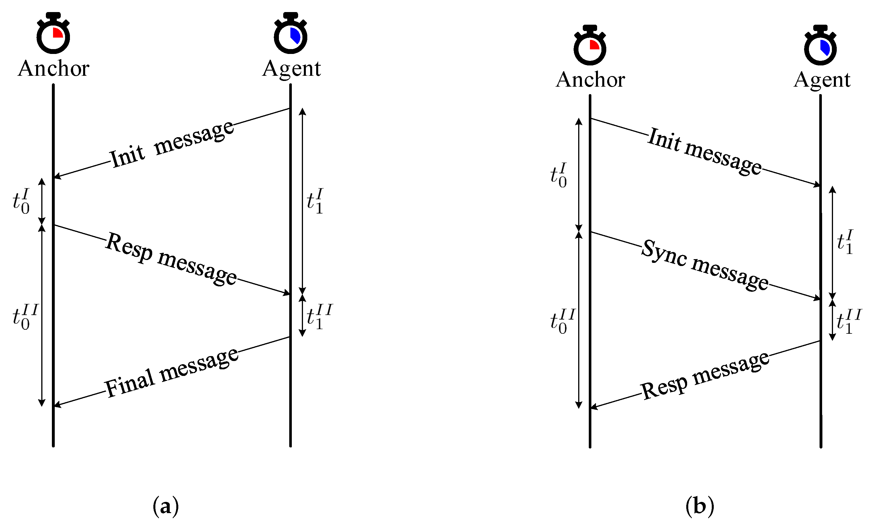
The localization protocol of the SAL method is based on the work in [47]. As shown in Figure 2, compared with the conventional ranging protocol (Figure 2a) that requires at least UWB signals for a N-agent system, the protocol in Figure 2b can determine all the TOAs within the minimum frames, i.e., UWB signals. Moreover, since the agents initial the measuring process in the conventional protocol (Figure 2a), the unengaged agent transmission order will incur message conflict at the anchor side. While for the protocol in Figure 2b, such conflicts can be avoided by broadcasting the response order in the first two messages.
In addition, if we reverse the structure in Figure 2a (i.e., the anchor broadcast the Init message, the agents return the Resp messages, and the anchor broadcast the Final message), it can also reduce the number of signals to and avoid conflicts. In this method, the distance measurement is obtained at the agent side, so it is an agent-based architecture. However, since the anchor is equipped with an antenna array, the angle measurement needs to be sent to the agent to achieve measurement fusion. Therefore, our proposed algorithm is not suitable for agent-based measurement. In our method, the distance and angle measurements in Figure 2b is obtained at the anchor side, which is an anchor-based architecture. Thus, the mentioned agent and anchor-based architectures are completely different. Last but not least, with the protocol in Figure 2b, we will show that our SAL method can further enhance the measurement efficiency by receiving concurrent agent responses from a single estimated CIR.
3.2. (Quasi-)simultaneous Response
In a common multi-agent measurement process [47], the anchor can only accept one message each time the receiver is turned on. Thus, for an -agent localization system, the anchor needs to open the receiver times to receive massages of all agents, which is time-consuming and inefficient.
We next introduce the concept of (quasi-)simultaneous response, which enables the anchor to receive all the agents’ responses in one estimated CIR and is the key enabler of the proposed SAL method. With the proposed method, the anchor only needs to open the receiver one time to serve agents. The main advantage of the proposed method is that the anchor serves all the agents simultaneously. For brevity, we introduce our method by taking the two-agent scenario as an example, which can be extended to multi-agent cases. Note that our method is not limited to a specific type of UWB chip or device, we only need to follow the corresponding manual to adjust the operating process.
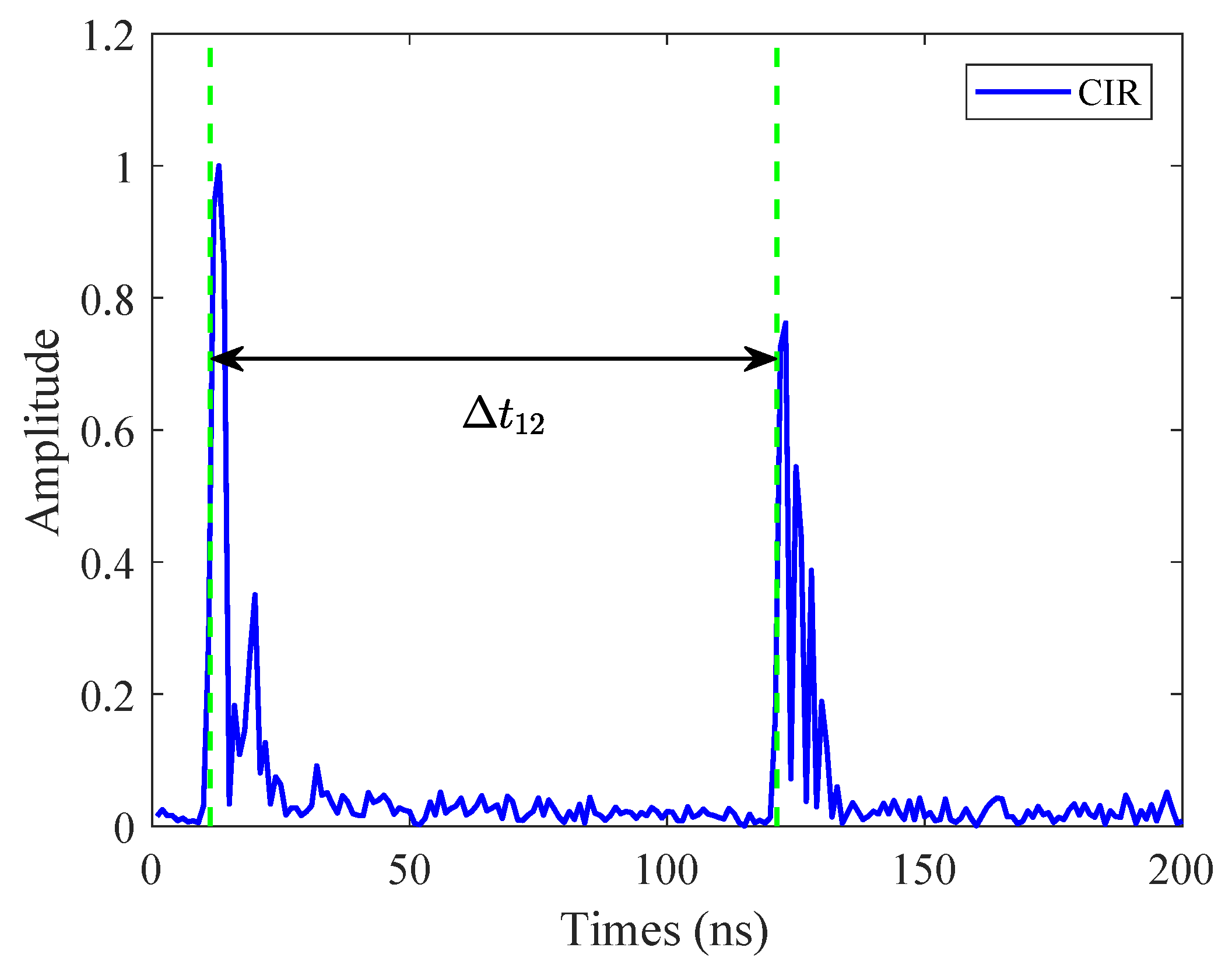
As shown in Figure 1b, the anchor broadcasts the first two messages to initiate the measurement process. In the payload of the Init message, the anchor writes the fixed time delay between the Init and Sync messages. The anchor also assigns a fixed delay to agent i and writes them into the payload. The purpose of introducing is to distinguish messages from different agents. Note that the capacity of the proposed SAL system is affected by , since represents an extra delay. However, MPCs may overlap with subsequent responses, which requires us to assgin larger delays and therefore limit the capacity of the system. In order to serve more agents in one waveform window with no waveform overlapping, we take the value of in tens of nanoseconds considering the general CIR register can receive a waveform with the period of 1016 nanoseconds [46]. An illustration of the received CIR is shown in Figure 3.
The proposed (quasi-)simultaneous response has similar concepts to the work in [35], but has different advantages. In [35], after multiple anchors send messages (quasi-)simultaneously, one agent receives the responses in a single estimated CIR, and uses the TDOA to locate itself. Since the anchor cannot know the agent’s location, this is an agent-based approach. In our method, by allowing agents to respond (quasi-)simultaneously, a single anchor can complete measurement process of all agents, thus the anchor can implement multi-agent localization, which is an anchor-based approach.
After receiving two messages, the agent can determine the clock drift ratio between its clock and the anchor’s clock, given by
Then, the agent i sends a Resp message after a predetermined delay , where the clock drift ratio (6) and the delay are written in the payload. When the anchor receives all the Resp messages, the measuring process completes. We denote that the first response corresponds to . Thus, the distance between agent 1 and the anchor is . The distance between the agent and the anchor is given by
In this way, the clock drift ratio can be estimated and the asynchronism effect can be mitigated, which leads to a high-accuracy distance estimation. Note that the estimation of the clock drift ratio is performed during each ranging process, which can reduce the effect of the clock drift in each measurement. The main advantages of this (quasi-)simultaneous response method are as follows:
- The anchor is able to extract the arrival time-stamp and phase of all agents in one CIR waveform, which significantly improves the efficiency of the TOA estimation.
- Within a certain distance difference, the anchor can complete the data association between the response and the agent. (Because the anchor assigns a different to each agent in advance.)
Note that high measurement efficiency means reducing the number of times that the anchor turns on the receiver, and it also means that the measurement takes less time. For scenarios where there are more than 2 agents, we only need to allocate different delays to different agents according to their device ID, so that the agents’ responses do not overlap, and the measuring process can be achieved.
4. Localization Algorithm
In this section, we present a peak detection algorithm for the anchor to effectively determine the Resp message. Then we introduce the phase of arrival estimation method to obtain phase observations, and design an ML-based localization algorithm to achieve high-accuracy localization.
4.1. Reliable Response Detection
Due to the limitations of the UWB chip, the CIR we obtained was sampled in nanoseconds [46]. We find that nanosecond time resolution can bring distance errors of more than ten centimeters. In addition, the chip has an embedded TOA estimation algorithm [46], which can estimate the TOA of the first response before the nanosecond sampling, so the TOA estimation of the first path given by the chip is more accurate, i.e., the time resolution is 15.65 ps. Thus, we directly estimate the TOA with the algorithm embedded in the devices [46]. Then, we use the interpolation technique to improve the time resolution of the observed CIR, and get more accurate TOA estimates for other responses. In practice, we use the sinc function for interpolation.
We calculate the amplitude of the complex CIR, and denote it as , where is the original time resolution and ns. Then we use the sinc function to interpolate the original sequence . The interpolation result is given by
In general, we extend the the time resolution by 64 times using interpolation technique so that the time resolution of is similar to 15.65 ps. Next, we extract the timestamp corresponding to the largest amplitude as the improved TOA estimation. TOA estimation after interpolation is more accurate than TOA estimation directly on the raw CIR.
Note that the largest peaks in the CIR are not necessarily the LOS MPCs of agents, since the NLOS MPCs can be stronger than the LOS MPC. However, the direct-path of each agent Resp message is generally stronger than its multipaths, so we can search for the largest amplitude of the i-th () agent’s first path near after the first response in a CIR.
After we obtain the TOA estimation of the responses from the agents, we can calculate the TDOA of a certain response and the first arrival response. Then the distance estimation can be calculated using (7).
4.2. Phase Estimation
The off-the-shelf UWB chip can provide the first path position within the CIR determined by the algorithm embedded. We can calculate the signal phase of arrival using the complex sample corresponding to the position. Since the CIR sampling interval is about 1 nanosecond, and the time resolution of the first path position given by the chip is sub-nanosecond, we take the mean of the phases near the first path position as the estimation of the first-path phase.
Since there are multiple responses in a single estimated CIR and the chip does not give the phase estimations of other responses, we design a simple and practical threshold detection method to estimate the phase of arrival. We first normalize as
Then we introduce a threshold ratio to detect the rising edge of a response where the phase can be extracted. Since the approximate time interval between responses are known in advance, we estimate the maximum amplitude of the noise using the partial CIR in the middle of any two responses, which is denoted by . To avoid mistakenly treating noise as responses, we let . The rising edge of a response usually lasts for less than 3 ns, so the number of sampling points on the rising edge is usually less than 4. In order to avoid missing detection of the sampling points on the rising edge, we try to make the threshold smaller. Besides, since each response will follow some large MPCs, we usually start detecting backwards at the middle of the responses to avoid false detections. When we find the sampling point whose amplitude first exceeds the threshold, the phase of the sample is considered the arrival phase of this signal.
4.3. ML-Based Localization Algorithm
After acquiring the measurement information, we can obtain the ranging and phase information of all agents. Then we use the observed phase to estimate the AOA of the agent relative to the anchor and calculate the position by using the propagation delay.
For the agent i, we estimate the propagation delay and the arrival phase from the signals. We calculate the AOA by solving the optimization problem as follows
where and are the AOA of agent i and reference phase estimations, respectively.
Finally, we use the geometric relationship to calculate the coordinates of agent i by . In the 3D scene, we introduce the estimation of the elevation angle [43]. Accordingly, the expression of agent coordinates becomes .
5. Experiment and Analysis
In this section, we evaluate the performance of the proposed SAL method by conducting experiments in an indoor circular hall environment and an indoor lab classroom environment based on our UWB system. Specifically, we first introduce the experiment settings. Then, we evaluate the performance of the system. The experiment results show that our system can achieve decimeter-level localization accuracy.
5.1. Experiment Settings
The anchor is equipped with a circular antenna array and multiple Decawave UWB chips [46]. To verify the lowest performance of single anchor localization, the antenna number is set as 3 in order to realize omnidirectional angle measuring. In particular, all antennas are utilized for receiving the Resp messages while only one antenna is used to send the Init and Sync messages. According to the IEEE 802.15.4 UWB channel standard [45], the pulse repetition frequency (PRF) is set as 64 MHz, the preamble symbol length is set as 128, and the preamble code index is set as 9 both for transmitting and receiving and the channel 1 is adopted. An illustration of the scenario with three agents and one anchor is shown in Figure 4.
We conduct two experiments: one is in an indoor hall environment E1 and the other is in an indoor lab classroom environment E2, where the CAD maps are shown in Figure 5a and Figure 6a, respectively. The E1 is a circular area with the inner and the outer ring radius of 7 m and 15 m, respectively. In E1, there are various reflection objects and scattering objects which have a negative impact on the results, such as walls, tables, chairs, indoor plants, and walking people, and the walking people will normally pass into the experimental environment, but will not block the LOS propagation. Besides, there are no more than three people in the scene at the same time. E2 is a rectangular room with a 6 m × 8 m = 48 m2 rectangular area. There are also many reflectors and scatters in the area, such as desks and chairs. In both environments, the anchor, represented by the red ring, is placed nearly in the center of the environment in order to provide better service for the agents. Both the anchor and the agents are placed at the height of 1.3 m, so that they are on the same two-dimensional plane. The root mean squared error (RMSE) and the Euclidean Distance are chosen as the performance metrics, and the Euclidean Distance between position and is given by .
5.2. Performance Evaluation
We randomly selected test points in E1 and test points in E2 to evaluate the fixed point localization performance, and each test point has measurements. Then we select a fixed trajectory in E2 to evaluate the tracking performance. The localization accuracy of the static agents and the moving agents are evaluated under fixed points and trajectories, respectively.
5.2.1. Static test point
We first evaluate the performance of the proposed SAL method under static scenarios in E1. Figure 5a also shows the results of the localization of the agents at different positions. We randomly select test points and performed measurements at each test point. We compare our proposed method with the normal SAL method (SAL-Normal) without any filtering algorithm [43], where the anchor locates each agent in order, and compare the performance under different number of agents. We first let and place one agent on all test points in turn to collect the localization results. Then, for , we randomly select 10 pairs of test points from all test points, and place two agents at each pair of test points at the same time for testing. For , we randomly select 3 test points from all test points to place agents every time. For simplicity, we analyze the results of and present other results in the final table (Table 1 and Table 2). In practice, due to the electromagnetic coupling between the antenna elements, there is a different bias for different angles of arrival. Thus, we use polynomial regression method [48] to reduce the fixed bias, and then the array will have a near-unbiased AOA estimation. Similarly, we also calibrate the ranging results, so that the ranging error is less than 10 cm.
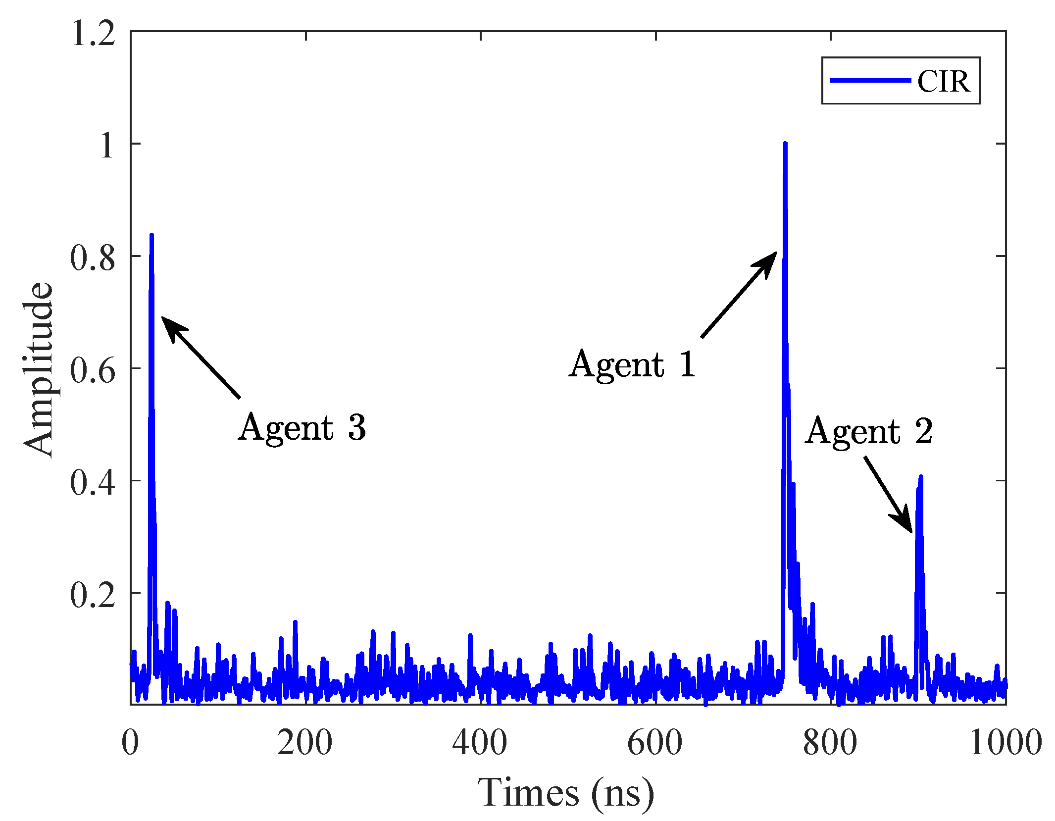
An illustration of the received CIR is shown in Figure 7. We randomly put three agents in the E1 environment (named Agent 1, Agent 2, and Agent 3, respectively), and set ns, ns, and ns, which means that Agent 2 will wait for an additional 150 ns before responding, and Agent 3 will wait for an additional 300 ns before responding. Note that the response of Agent 3 appears at the front of the CIR. This is because the CIR is the accumulation of the correlation results, and the part that exceeds the current window will be moved to the front [46].
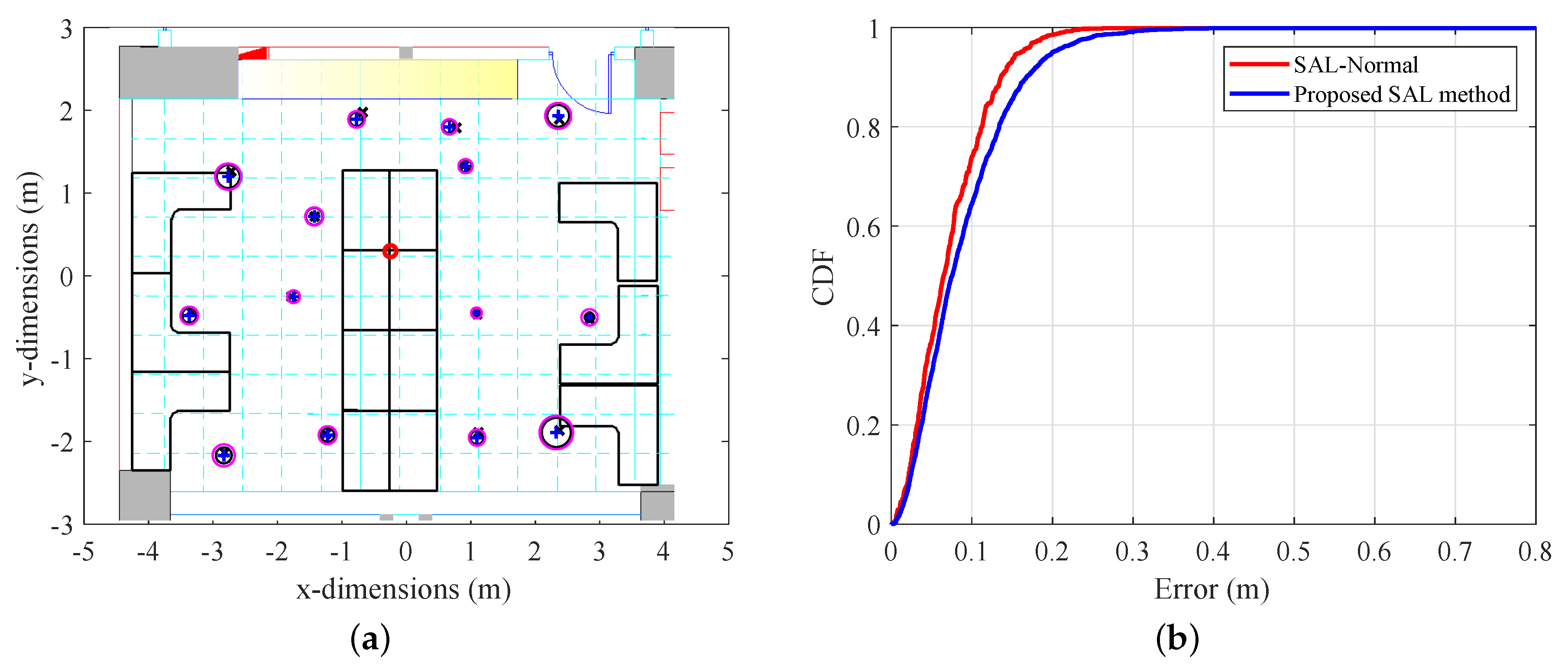
As shown in Figure 5a, The black cross indicates the true position of the test points, the blue plus sign indicates the mean of the actual localization results, the black circle represents the RMSE when the anchor locates three agents using the SAL-Normal, and the magenta circle represents the RMSE when the anchor locates three agents using the proposed SAL method. As expected, the estimated position of the agents is close to the ground truth, and the Euclidean distance between the mean of the localization result and the ground truth is less than 10 cm. Moreover, the localization RMSE when the anchor locates three agents using the proposed SAL method is greater than the localization RMSE when using SAL-Normal. The reason is that when using the proposed SAL method, the anchor can obtain delay and phase observation of multiple agents in a single CIR estimation. The phase of arrival of the first path estimated by the UWB chip is more accurate than other phase of arrival estimations. It can be expected that as the number of agents increases, the localization accuracy will decrease more and more slowly. The reason is that only the first responding agent has high-precision phase observation. However, the CIR of the anchor is only 1016 nanoseconds long, thus the number of agents that can be simultaneously localized is limited in order to avoid overlap of the responses of different agents.
To quantify the overall localization performance of the system, we analyze the statistical characteristics of the localization error based on the CDF. Figure 5b shows the performance comparison when using SAL-Normal and the proposed SAL method with . When using SAL-Normal, the system can reach a 90% error of 20.6 cm and a median error of 10.3 cm. When using the proposed sal method, a 90% error and median error of 23.4 cm and 10.5 cm are achieved, respectively. The results show that the performance of the proposed method can almost reach the traditional method.
In order to validate our localization system in other environments, we have selected a smaller lab classroom (E2) with a CAD map shown in Figure 6a. The size of the room is about 6 m × 8 m = 48 m2, with more desks, cabinets, chairs, and other reflection objects and scattering objects. As shown in Figure 6a, we randomly selected test points and performed measurements at each test point. As in the previous experimental approach, we evaluate the performance of the system using SAL-Normal and the proposed SAL method, respectively. The results show that the estimated position is close to the ground truth, and the performance is better when using SAL-Normal. Figure 6b shows the CDF comparison when using different localization methods in E2. When using SAL-Normal, a 90% error of 13.8 cm and median error of 6.7 cm are achieved. When using the proposed sal method, the 90% error is 16.8 cm and the median error is 7.5 cm. The conclusion of the experiment is similar to that in E1. The results also show that the performance in the lab classroom is better than in the hall. This is because the test points we select in the classroom are closer to the anchor, and the localization error caused by the aoa estimation error is smaller. In addition, the increase in reflectors and scatterers has little effect on the localization performance, thanks to the existence of LOS propagation.
To further analyze the source of the localization error, we analyzed the ranging error and angle estimation error of three agents in both scenarios. Specifically, the mean of distance measurement error is less than 10 cm, the standard deviation of the distance measurements is 3.2 cm, the mean of angle estimation error is less than 2 degrees, and the standard deviation of the angle measurements is 3 degrees. Therefore, when the agent is far away from the anchor, i.e., 2 m away, the angle estimation error is the main source of localization error. As the distance increases, the angle estimation error will introduce a larger localization error, which can be improved by increasing the antenna number.
To evaluate the localization performance for different number of agents, we employ agents in both E1 and E2. The 90% and median localization error with different agent number in the two test environment is shown in Table 1 and Table 2. In both tables, the results show that when using SAL-Normal, the overall localization performance does not increase with the number of agents. When using the proposed sal method, the localization accuracy will decrease slightly with the increase of the agent number. Also, we find that the localization accuracy of two agents and three agents is similar when using the proposed SAL method, which shows our method will not be fragile in multi-agent scenarios. In general, our method is a little bit worse than the normal method in terms of positioning accuracy, but it can achieve decimeter-level localization accuracy, which is enough for practical use.
5.2.2. Tracking Performance
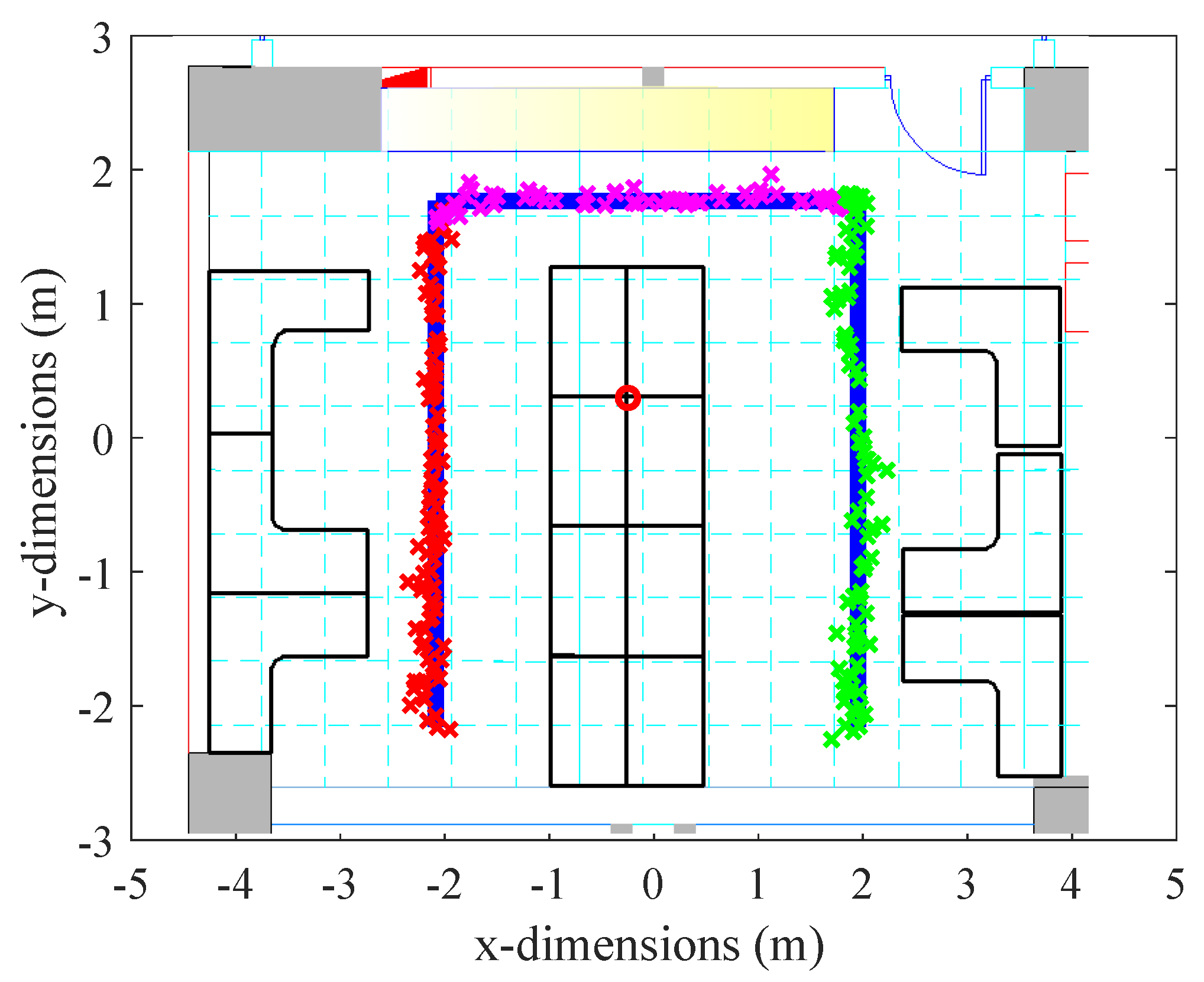
In the previous experiment, we evaluated the agents’ localization performance at the selected test points. To further evaluate the performance of the localization system in a dynamic scenario, we let the agents move along a preset route in E2 (see Figure 8). In practice, we hold the UWB device and walk at a near-constant speed along the preset route. In addition, we make the agent and anchor close in height to better achieve two-dimensional localization. In the experiment, we employ three agents (agent 1, agent 2, and agent 3) as an example to evaluate the performance of our system. As shown in Figure 8, we let the three agents go straight along the three sides of the rectangle, respectively. The red circle represents the anchor, the semi-rectangular blue line is the preset route, the red cross sign is the tracking result of agent 1 starting from the left bottom, the magenta cross is the tracking result of agent 2 starting from the left top, and the green cross is the tracking result of agent 3 starting form the right top. The results show that the trajectory estimation of the three agents can well follow the preset route. Since it is not easy to relate the real-time position estimation to the ground truth, real-time localization errors cannot be counted. Note that the localization results are raw data, which means we do not use any filtering algorithms. The experimental results verify the potential of our system in practice application.
5.2.3. Time Consumption
In Table 3, we count the time taken to complete measurements for agents when using different methods. The results show that the elapsed time of SAL-Normal increases linearly with increasing agents and the elapsed time of the proposed SAL method does not change as the agent number increases. In SAL-Normal, the anchor serves each agent one by one, so all agents are located in turn. However, in the proposed SAL method, all agents send Resp messages to the anchor (quasi-)simultaneously, and the anchor can estimate the TOA and AOA of the agents in a single estimated CIR. We find that the efficiency of measurement increases as the number of agents increases when using the proposed SAL method. Therefore, our method can improve measurement efficiency in multi-agent localization scenarios while ensuring decimeter-level localization accuracy. Note that the actual workflow can be further optimized, so the time consumption of the two method can be further reduced. The table is intended to illustrate the overall difference in time consumption between the two methods.
6. Conclusions
In this paper, we proposed a high-efficiency SAL method, which serves multiple agents based on the single-anchor UWB system with minimum exchanges of signals. In such systems, the anchor equipped with an antenna array achieves localization of multiple agents by using range and AOA estimations. During the measurement process, the anchor only needs to turn on the receiver once to complete the measurement of all agents, which improves the measurement efficiency. We implemented our method on a single-anchor UWB system and evaluated the localization accuracy and measurement efficiency in two indoor environments. The results show that our system can achieve decimeter-level localization accuracy and the measurement time does not increase with the number of agents, within a certain number of agents.
There are still several issues to be further studied, such as the effect of multi-path and NLOS propagation for the proposed SAL system. In future work, we will also conduct sufficient experiments in more complex environments, and design algorithms to improve system capacity and localization accuracy.
Author Contributions
Conceptualization, T.W. and Y.S.; methodology, T.W. and H.Z.; software, T.W.; validation, T.W.; formal analysis, T.W. and H.Z.; investigation, T.W.; resources, T.W., H.Z. and Y.S.; data curation, T.W.; writing—original draft preparation, T.W.; writing—review and editing, T.W., H.Z., and Y.S.; visualization, T.W.; supervision, H.Z. and Y.S.; project administration, T.W., H.Z. and Y.S.; funding acquisition, Y.S. All authors have read and agreed to the published version of the manuscript.
Funding
This research was supported by the National Natural Science Foundation of China under Grant 61871256, 91638204, and 61811530329.
Acknowledgments
Authors thank Feng Ge for providing technical support and practical comments on embedded development. Authors also thank Haipeng Lu for collecting experimental data used in the case study.
Conflicts of Interest
The authors declare no conflict of interest.
Abbreviations
The following abbreviations are used in this manuscript:
| SAL | single-anchor localization |
| GNSS | Global Navigation Satellite System |
| MPC | multipath component |
| NLOS | non-line-of-sight |
| RF | radio frequency |
| RFID | radio-frequency identification |
| RSSI | received signal strength indicator |
| LF | location fingerprints |
| AOA | angle-of-arrival |
| UWB | ultra-wideband |
| CIR | channel impulse response |
| ToF | time-of-flight |
| TDOA | time-difference-of-arrival |
| TOA | time-of-arrival |
| PDOA | phase-difference-of-arrival |
| ML | maximum likelihood |
| LOS | line-of-sight |
| RMSE | root mean squared error |
| CDF | cumulative distribution function |
References
- Win, M.Z.; Dai, W.; Shen, Y.; Chrisikos, G.; Poor, H.V. Network operation strategies for efficient localization and navigation. Proc. IEEE 2018, 106, 1224–1254. [Google Scholar] [CrossRef]
- Seçkin, A.Ç.; Coşkun, A. Hierarchical fusion of machine learning algorithms in indoor positioning and localization. Appl. Sci. 2019, 9, 3665. [Google Scholar] [CrossRef] [Green Version]
- Dai, W.; Shen, Y.; Win, M.Z. Energy-efficient network navigation algorithms. IEEE J. Se. Areas Commun. 2015, 33, 1418–1430. [Google Scholar] [CrossRef]
- Yuan, W.; Wu, N.; Etzlinger, B.; Wang, H.; Kuang, J. Cooperative joint localization and clock synchronization based on Gaussian message passing in asynchronous wireless networks. IEEE Trans. Veh. Technol. 2016, 65, 7258–7273. [Google Scholar] [CrossRef] [Green Version]
- Witrisal, K.; Meissner, P.; Leitinger, E.; Shen, Y.; Gustafson, C.; Tufvesson, F.; Haneda, K.; Dardari, D.; Molisch, A.F.; Conti, A.; et al. High-accuracy localization for assisted living: 5G systems will turn multipath channels from foe to friend. IEEE Signal Process. Mag. 2016, 33, 59–70. [Google Scholar] [CrossRef]
- Win, M.Z.; Conti, A.; Mazuelas, S.; Shen, Y.; Gifford, W.M.; Dardari, D.; Chiani, M. Network localization and navigation via cooperation. IEEE Commun. Mag. 2011, 49, 56–62. [Google Scholar] [CrossRef]
- Li, J.; Yue, X.; Chen, J.; Deng, F. A novel robust trilateration method applied to ultra-wide bandwidth location systems. Sensors 2017, 17, 795. [Google Scholar] [CrossRef] [Green Version]
- Liu, Z.; Dai, W.; Win, M.Z. Mercury: An infrastructure-free system for network localization and navigation. IEEE Trans. Mob. Comput. 2017, 17, 1119–1133. [Google Scholar] [CrossRef]
- Xiao, F.; Wang, Z.; Ye, N.; Wang, R.; Li, X. One more tag enables fine-grained RFID localization and tracking. IEEE/ACM Trans. Netw. 2018, 26, 161–174. [Google Scholar] [CrossRef]
- Kolakowski, M. Improving accuracy and reliability of bluetooth low-energy-based localization systems using proximity sensors. Appl. Sci. 2019, 9, 4081. [Google Scholar] [CrossRef] [Green Version]
- Xiong, Y.; Wu, N.; Shen, Y.; Win, M.Z. Cooperative network synchronization: Asymptotic analysis. IEEE Trans. Signal Process. 2017, 66, 757–772. [Google Scholar] [CrossRef]
- Kotaru, M.; Joshi, K.; Bharadia, D.; Katti, S. Spotfi: Decimeter level localization using wifi. ACM SIGCOMM Comput. Commun. Rev. 2015, 45, 269–282. [Google Scholar] [CrossRef]
- Sadowski, S.; Spachos, P. Rssi-based indoor localization with the internet of things. IEEE Access 2018, 6, 30149–30161. [Google Scholar] [CrossRef]
- Monfared, S.; Nguyen, T.H.; Petrillo, L.; De Doncker, P.; Horlin, F. Experimental demonstration of BLE transmitter positioning based on AOA estimation. In Proceedings of the 2018 IEEE 29th Annual International Symposium on Personal, Indoor and Mobile Radio Communications, Bologna, Italy, 9–12 September 2018; pp. 856–859. [Google Scholar]
- Bartoletti, S.; Dai, W.; Conti, A.; Win, M.Z. A mathematical model for wideband ranging. IEEE J. Sel. Top. Signal Process. 2014, 9, 216–228. [Google Scholar] [CrossRef]
- Jiménez, A.R.; Seco, F. Comparing ubisense, bespoon, and decawave uwb location systems: Indoor performance analysis. IEEE Trans. Instrum. Meas. 2017, 66, 2106–2117. [Google Scholar] [CrossRef]
- Conti, A.; Mazuelas, S.; Bartoletti, S.; Lindsey, W.C.; Win, M.Z. Soft information for localization-of-things. Proc. IEEE 2019, 107, 2240–2264. [Google Scholar] [CrossRef] [Green Version]
- Shi, G.; Ming, Y. Survey of indoor positioning systems based on ultra-wideband (UWB) technology. Wirel. Commun. Netw. Appl. 2016, 1269–1278. [Google Scholar]
- Mazuelas, S.; Conti, A.; Allen, J.C.; Win, M.Z. Soft range information for network localization. IEEE Trans. Signal Process. 2018, 66, 3155–3168. [Google Scholar] [CrossRef]
- Dardari, D.; Closas, P.; Djurić, P.M. Indoor tracking: Theory, methods, and technologies. IEEE Trans. Veh. Technol. 2015, 64, 1263–1278. [Google Scholar] [CrossRef] [Green Version]
- Monica, S.; Ferrari, G. UWB-based localization in large indoor scenarios: Optimized placement of anchor nodes. IEEE Trans. Aerosp. Electron. Syst. 2015, 51, 987–999. [Google Scholar] [CrossRef]
- Win, M.Z.; Shen, Y.; Dai, W. A theoretical foundation of network localization and navigation. Proc. IEEE 2018, 106, 1136–1165. [Google Scholar] [CrossRef]
- Yang, M.; Jackson, D.R.; Chen, J.; Xiong, Z.; Williams, J.T. A TDOA localization method for nonline-of-sight scenarios. IEEE Trans. Antennas Propag. 2019, 67, 2666–2676. [Google Scholar] [CrossRef]
- Chen, J.; Dai, W.; Shen, Y.; Lau, V.K.; Win, M.Z. Resource management games for distributed network localization. IEEE J. Sel. Areas Commun. 2017, 35, 317–329. [Google Scholar] [CrossRef]
- Huang, S.; Wu, Z.; Misra, A. A practical, robust and fast method for location localization in range-based systems. Sensors 2017, 17, 2869. [Google Scholar] [CrossRef] [PubMed] [Green Version]
- Dai, W.; Shen, Y.; Win, M.Z. A computational geometry framework for efficient network localization. IEEE Trans. Inf. Theory 2017, 64, 1317–1339. [Google Scholar] [CrossRef]
- Corbalán, P.; Picco, G.P.; Palipana, S. Chorus: UWB concurrent transmissions for GPS-like passive localization of countless targets. In Proceedings of the 18th International Conference on Information Processing in Sensor Networks, Montreal, QC, Canada, 15–18 April 2019; pp. 133–144. [Google Scholar]
- Win, M.Z.; Meyer, F.; Liu, Z.; Dai, W.; Bartoletti, S.; Conti, A. Efficient multisensor localization for the Internet of Things: Exploring a new class of scalable localization algorithms. IEEE Signal Process. Mag. 2018, 35, 153–167. [Google Scholar] [CrossRef] [Green Version]
- Horváth, K.A.; Ill, G.; Milánkovich, Á. Passive extended double-sided two-way ranging with alternative calculation. In Proceedings of the 2017 IEEE 17th International Conference on Ubiquitous Wireless Broadband, Salamanca, Spain, 12–15 September 2017; pp. 1–5. [Google Scholar]
- Gholami, M.R.; Gezici, S.; Ström, E.G. Improved position estimation using hybrid TW-TOA and TDOA in cooperative networks. IEEE Trans. Signal Process. 2012, 60, 3770–3785. [Google Scholar] [CrossRef]
- Neirynck, D.; Luk, E.; McLaughlin, M. An alternative double-sided two-way ranging method. In Proceedings of the 2016 13th Workshop on Positioning, Navigation and Communications, Bremen, Germany, 19–20 October 2016; pp. 1–4. [Google Scholar]
- Tiemann, J.; Elmasry, Y.; Koring, L.; Wietfeld, C. ATLAS FaST: Fast and simple scheduled TDOA for reliable ultra-wideband localization. In Proceedings of the 2019 International Conference on Robotics and Automation, Montreal, QC, Canada, 20–24 May 2019; pp. 2554–2560. [Google Scholar]
- Horváth, K.A.; Ill, G.; Milánkovich, Á. Passive extended double-sided two-way ranging algorithm for UWB positioning. In Proceedings of the 2017 Ninth International Conference on Ubiquitous and Future Networks, Milan, Italy, 4–7 July 2017; pp. 482–487. [Google Scholar]
- Pelka, M.; Hellbrück, H. S-TDoA—Sequential time difference of arrival—A scalable and synchronization free approach for positioning. In Proceedings of the 2016 IEEE Wireless Communications and Networking Conference, Doha, Qatar, 3–6 April 2016; pp. 1–6. [Google Scholar]
- Gro<i>β</i>windhager, B.; Stocker, M.; Rath, M.; Boano, C.A.; Römer, K. SnapLoc: An ultra-fast UWB-based indoor localization system for an unlimited number of tags. In Proceedings of the 2019 18th ACM/IEEE International Conference on Information Processing in Sensor Networks, Montreal, QC, Canada, 15–18 April 2019; pp. 61–72. [Google Scholar]
- Vecchia, D.; Corbalán, P.; Istomin, T.; Picco, G.P. Playing with fire: Exploring concurrent transmissions in ultra-wideband radios. In Proceedings of the 2019 16th Annual IEEE International Conference on Sensing, Communication, and Networking, Boston, MA, USA, 10–13 June 2019; pp. 1–9. [Google Scholar]
- Mendrzik, R.; Meyer, F.; Bauch, G.; Win, M.Z. Enabling Situational Awareness in Millimeter Wave Massive MIMO Systems. IEEE J. Sel. Top. Signal Process. 2019, 13, 1196–1211. [Google Scholar] [CrossRef]
- Han, Y.; Shen, Y.; Zhang, X.P.; Win, M.Z.; Meng, H. Performance limits and geometric properties of array localization. IEEE Trans. Inf. Theory 2015, 62, 1054–1075. [Google Scholar] [CrossRef] [Green Version]
- Dotlic, I.; Connell, A.; Ma, H.; Clancy, J.; McLaughlin, M. Angle of arrival estimation using decawave dw1000 integrated circuits. In Proceedings of the 2017 14th Workshop on Positioning, Navigation and Communications, Bremen, Germany, 25–26 October 2017; pp. 1–6. [Google Scholar]
- Wang, Y.; Wu, Y.; Shen, Y. Joint spatiotemporal multipath mitigation in large-scale array localization. IEEE Trans. Signal Process. 2018, 67, 783–797. [Google Scholar] [CrossRef]
- Rzymowski, M.; Woznica, P.; Kulas, L. Single-anchor indoor localization using ESPAR antenna. IEEE Antenna Wirel. Propag. Lett. 2015, 15, 1183–1186. [Google Scholar] [CrossRef]
- Yao, F.; Wang, Y.; Guan, X. Joint time synchronization and localization for target sensors using a single mobile anchor with position uncertainties. In Proceedings of the IEEE International Conference on Acoustics, Speech and Signal Processing, Calgary, AB, Canada, 15–20 April 2018; pp. 3794–3798. [Google Scholar]
- Wang, T.; Zhao, H.; Shen, Y. High-accuracy localization using single-anchor ultra-wide bandwidth systems. In Proceedings of the 2019 IEEE/CIC International Conference on Communications in China, Changchun, China, 11–13 August 2019; pp. 59–63. [Google Scholar]
- Liu, Y.; Shen, Y.; Win, M.Z. Single-anchor localization and synchronization of full-duplex agents. IEEE Trans. Commun. 2018, 67, 2355–2367. [Google Scholar] [CrossRef]
- IEEE 802 Working Group. IEEE standard for local and metropolitan area networks–Part 15.4: Low-rate wireless personal area networks (lr-wpans). IEEE Std. 2011, 802, 4–2011. [Google Scholar]
- DecaWave Ltd. DW1000 User Manual; Decawave Ltd.: Dublin, Ireland, 2015. [Google Scholar]
- Zhang, Z.; Zhao, H.; Shen, Y. High-efficient ranging algorithms for wireless sensor network. In Proceedings of the 2019 IEEE International Conference on Wireless Communications and Signal Processing, Xi’an, China, 23–25 October 2019; pp. 1–6. [Google Scholar]
- Fan, J.; Gijbels, I. Variable bandwidth and local linear regression smoothers. Ann. Stat. 1992, 20, 2008–2036. [Google Scholar] [CrossRef]
Figure 1.
An illustration of the proposed SAL method. For brevity, we take the two-agent scenario as an example, which can be extended to multi-agent cases. (a) The relationship between the anchor and the agents. (b) The message exchange process.
Figure 1.
An illustration of the proposed SAL method. For brevity, we take the two-agent scenario as an example, which can be extended to multi-agent cases. (a) The relationship between the anchor and the agents. (b) The message exchange process.

Figure 2.
Comparison of two extended two-way ranging methods. (a) Traditional way of extended two-way ranging methods. (b) Improved way of extended two-way ranging methods.
Figure 2.
Comparison of two extended two-way ranging methods. (a) Traditional way of extended two-way ranging methods. (b) Improved way of extended two-way ranging methods.

Figure 3.
An illustration of the received channel impulse response (CIR) at the anchor from two agents’ Resp messages. We introduce an individual delay so that the pulses can avoid overlap and avoid strong multipaths. indicates the time-difference-of-arrival (TDOA) of two responses.
Figure 3.
An illustration of the received channel impulse response (CIR) at the anchor from two agents’ Resp messages. We introduce an individual delay so that the pulses can avoid overlap and avoid strong multipaths. indicates the time-difference-of-arrival (TDOA) of two responses.

Figure 4.
Experimental environment illustration. Three agents and a single anchor are shown as an example in an indoor environment.
Figure 4.
Experimental environment illustration. Three agents and a single anchor are shown as an example in an indoor environment.

Figure 5.
Localization results in E1 and the cumulative distribution function (cumulative distribution function (CDF)) comparison. (a) The mean localization results (blue plus sign) and the root mean squared error (RMSE) (black circles for SAL-Normal, and magenta circles for the proposed SAL method) on each selected test point (black cross). (b) The CDF comparison of the two localization methods in E1.

Figure 6.
Localization results in E2 and the CDF comparison. (a) The mean localization results (blue plus sign) and the RMSE (black circles for SAL-Normal, and magenta circles for the proposed SAL method) on each selected test point (black cross). (b) The CDF comparison of the two localization methods in E2.

Figure 7.
An illustration of the received CIR at the anchor from three agents’ Resp messages. We introduce an individual delay ns, ns, and ns so that the pulses can avoid overlap and avoid strong multipaths.
Figure 7.
An illustration of the received CIR at the anchor from three agents’ Resp messages. We introduce an individual delay ns, ns, and ns so that the pulses can avoid overlap and avoid strong multipaths.

Figure 8.
The tracking results of three agents (red cross, magenta cross, and green cross) moving on the preset route (blue line).
Figure 8.
The tracking results of three agents (red cross, magenta cross, and green cross) moving on the preset route (blue line).


Table 1.
Localization error comparison in E1.
| Errors | Methods | = 1 | = 2 | = 3 |
|---|---|---|---|---|
| 90% error | SAL-Normal | 20.4 cm | 20.8 cm | 20.6 cm |
| Proposed SAL method | 21.3 cm | 23.0 cm | 23.4 cm | |
| Median error | SAL-Normal | 9.3 cm | 9.3 cm | 10.3 cm |
| Proposed SAL method | 10.1 cm | 10.9 cm | 10.5 cm |
Table 2.
Localization error comparison in E2.
| Errors | Methods | = 1 | = 2 | = 3 |
|---|---|---|---|---|
| 90% error | SAL-Normal | 14.0 cm | 13.6 cm | 13.8 cm |
| Proposed SAL method | 13.6 cm | 16.0 cm | 16.8 cm | |
| Median error | SAL-Normal | 6.8 cm | 6.5 cm | 6.7 cm |
| Proposed SAL method | 6.5 cm | 7.3 cm | 7.5 cm |
Table 3.
Elapsed time comparison.
| Methods | = 1 | = 2 | = 3 |
|---|---|---|---|
| SAL-Normal | 3.4 ms | 6.8 ms | 10.2 ms |
| Proposed SAL method | 3.4 ms | 3.4 ms | 3.4 ms |
© 2019 by the authors. Licensee MDPI, Basel, Switzerland. This article is an open access article distributed under the terms and conditions of the Creative Commons Attribution (CC BY) license (http://creativecommons.org/licenses/by/4.0/).
Share and Cite
MDPI and ACS Style
Wang, T.; Zhao, H.; Shen, Y. An Efficient Single-Anchor Localization Method Using Ultra-Wide Bandwidth Systems. Appl. Sci. 2020, 10, 57. https://doi.org/10.3390/app10010057
AMA Style
Wang T, Zhao H, Shen Y. An Efficient Single-Anchor Localization Method Using Ultra-Wide Bandwidth Systems. Applied Sciences. 2020; 10(1):57. https://doi.org/10.3390/app10010057
Chicago/Turabian StyleWang, Tianyu, Hanying Zhao, and Yuan Shen. 2020. "An Efficient Single-Anchor Localization Method Using Ultra-Wide Bandwidth Systems" Applied Sciences 10, no. 1: 57. https://doi.org/10.3390/app10010057
Note that from the first issue of 2016, this journal uses article numbers instead of page numbers. See further details here.