
Elastic Gauge Wheel with Irregular Cavity for Improving Seed Furrow Structure and Seeding Quality
1
Key Laboratory of Bionics Engineering, Ministry of Education, Jilin University, Changchun 130025, China
2
College of Biological and Agricultural Engineering, Jilin University, Changchun 130025, China
3
Jilin Agricultural Machinery Research Institute, Changchun 130022, China
*
Author to whom correspondence should be addressed.
Agriculture 2023, 13(7), 1438; https://doi.org/10.3390/agriculture13071438
Submission received: 19 June 2023
/
Revised: 11 July 2023
/
Accepted: 19 July 2023
/
Published: 21 July 2023
(This article belongs to the Section Agricultural Technology)
Abstract
:The traditional gauge wheel has poor performance in reducing the adhesion to soil and constructing seed furrow, which results in lower seeding quality of the planter. To reduce the adhesion of the gauge wheel to the soil and build a well-structured seed furrow, an elastic gauge wheel with soil retention groove and irregular cavity was designed in this study. The soil retention groove built ridges on both sides of the seed furrow and avoided the gauge wheel compacting the seed furrow sidewalls. The irregular cavity increased the elasticity of the gauge wheel and allowed the wheel to squeeze the soil on both sides of the seed furrow, which reduced the soil adhesion of the wheel and built stable ridges. Soil moisture content was chosen as the experimental factor for comparative tests to evaluate the soil adhesion and the constructed seed furrow of the gauge wheel with an irregular cavity and the traditional gauge wheel. The experimental results showed that the viscosity reduction rate of the gauge wheel with the irregular cavity was not less than 12.61%. Compared with the traditional gauge wheel, the seed furrow constructed by the irregular cavity gauge wheel had ridges on both sides and less backfill soil, and the soil compaction of sidewalls decreased by 18.16%. The field experiment was designed using the Box–Behnken design. The working speed, downforce, and planting depth were taken as experimental factors, and the soil adhesion of the gauge wheel and the consistency of planting depth were taken as evaluation indicators. The optimal operating parameters of planter obtained by Design-Expert 8.0.6 software were as follows: the working speed was 8 km·h−1, the downforce was 844 N, and the planting depth was 65 mm. The verification test of the optimal operating parameters showed that the soil adhesion mass of the gauge wheel was 123.65 g and the coefficient of variation of the planting depth was 5.35%. This study provides a reference for the mechanized construction method of seed furrow by precision planter and the structural design and performance optimization of gauge wheels.
1. Introduction
Precision seeding, one of the seeding methods, is to sow seeds to a certain depth of soil with a certain row spacing and grain spacing according to the agronomic requirements [1,2,3]. Precision seeding can save seeds, promote crop growth and increase crop yields [4,5,6]. The key to precision seeding is to construct seed furrows [7]. A seed furrow with the same shape and depth can improve the uniformity of seed distribution and the consistency of planting depth. In addition, it can provide a suitable soil environment for seed germination and seedling growth [8,9].
The planter uses an opener to construct the seed furrow. An opener with good performance can build a seed furrow with the same depth and shape. The opener is required to cut through the soil easily, without disturbing the soil layers and with low working resistance [10]. Researchers have designed a variety of openers based on agronomic requirements and field soil characteristics [11,12,13,14]. Among them, the double-disk opener has been widely used in precision planters, and has the advantages of stable operation performance, neat groove shape and small soil disturbance [15,16]. The gauge wheel, one of the key components of the precision planter ditching device, is fitted to both sides of the double-disk opener [17,18,19]. It is mainly used to control the furrow depth and avoid soil clods and crop residues entering the opener [20]. The depth of the seed furrow is determined by the vertical distance between the gauge wheel and the double-disk opener. The depth of the seed furrow can be changed by adjusting the relative height of the gauge wheel and the opener.
Chernozem is a soil type in the agricultural region of northeastern China that is clayey with strong expansion and contraction and disturbance characteristics [21,22]. Soil adhering to the gauge wheel reduces the consistency of the furrow depth. The application of elastic materials, bionics, and mechanical vibrations can effectively decrease the mass of adhering soil to the wheel [23,24,25]. The gauge wheel, which imitates biological concave and convex surfaces, reduces soil adhesion but has a negative effect on the uniformity of furrow depth. It is more suitable for the gauge wheel by applying elastic materials or increasing the elasticity of the wheel to reduce soil adhesion. Styrene-butadiene rubber is widely used in the production of tires, hoses, medical appliances and various rubber products due to its good wear resistance, heat resistance, oil resistance and aging resistance characteristics. Jia et al. [26] designed an elastic press wheel with a double-cavity structure using styrene-butadiene rubber, and the study showed that the rubber materials and a reasonable cavity structure could improve the stability of the covering soil depth and strength of compaction of the press wheel. Jia et al. [27] combined bionics with vibration to design a profiling elastic press roller, which solved the problem of large soil adhesion and large slip rate of profiling elastic press rollers. Currently, styrene-butadiene rubber is commonly used as the material of gauge wheels, and elliptical cavities are designed to improve the elasticity of gauge wheels.
During the operation of a precision planter, the double-disk opener relies on the self-mass of the planter to press into the soil layer as the gauge wheels roll along the ground. The two disks rotate to cut through the soil and push it to the sides to form a V-shaped seed furrow of a certain depth [28]. Consistency in depth and shape is the key to a good seed furrow [29]. The soil compaction of the furrow sidewall is required to be low, which allows the seedling roots to grow in all directions and absorb nutrients [30]. The outer contour of the traditional gauge wheel is flat. Most of the soil pushed to both sides by the opener is flattened and fixed on both sides of the furrow by the gauge wheel, and a small amount of soil is backfilled into the furrow. The traditional gauge wheel compacts the sidewalls of the furrow, reducing the actual furrow depth and the soil used to cover the seed on both sides of the furrow. The soil compaction of the furrow sidewalls affects the growth of seedling root. The high soil compaction of furrow sidewalls makes seedling roots grow along the direction of the seed furrow, which affect the growth and development of crops [31,32]. The increase in the amount of backfill soiled in the furrow results in a furrow depth of less than the target depth. In addition, the reduction in loose soil on both sides of the furrow increases the difficulty of subsequent soil covering. A shallower furrow depth and decrease in soil cover results in shallower planting depth. Insufficient furrow depth and reduction in soil used to cover seeds results in insufficient seedling depth. Insufficient seedling depth causes poor root development, poor uptake of nutrients and water, and seedling death [33,34].
In this study, an elastic gauge wheel with a soil retention groove and irregular cavity was designed to improve seed furrow structure and seeding quality. The irregular cavity was designed to increase the elasticity of the wheel, which reduces the adhesion of the gauge wheel to soil. The soil retention groove was designed to reduce the compressive force of the gauge wheel on the seed furrow sidewalls, which reduces the soil compaction of furrow sidewalls. The ANSYS finite element emulation method was used to investigate the effect of the irregular cavity gauge wheel on the ground. The working performance of the irregular cavity gauge wheel was evaluated using soil bin and field experiments.
2. Materials and Methods
2.1. Structure and Principle
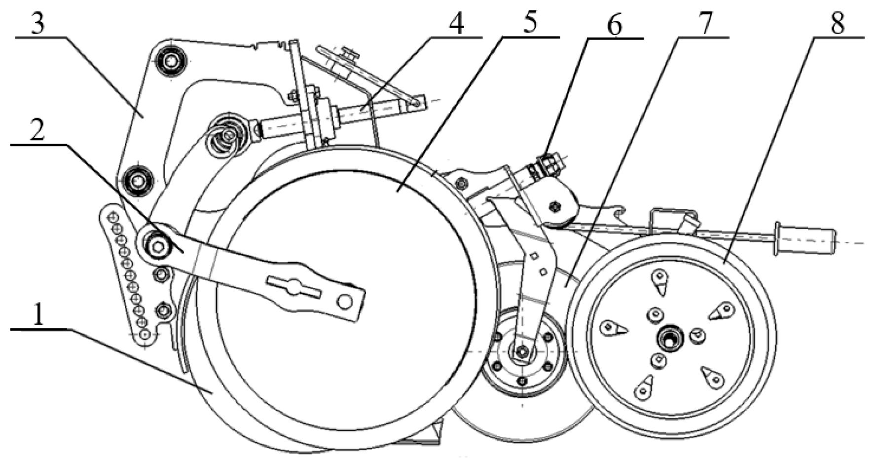
The planting unit is mainly composed of a frame, a double-disk opener, gauge wheels, a seed firmer, and a soil covering wheel, as shown in Figure 1. Gauge wheels were mounted on both sides of the double-disk opener using the gauge wheel arm. The gauge wheel rolled under the traction of the gauge wheel arm, which effectively reduced the hilling soil [35]. The depth regulator was used to adjust the relative height of the gauge wheel and the opener, i.e., the furrow depth. A position stopper was set at the end of the depth regulator mechanism to maintain the upper-limit position of the gauge wheel arm and the gauge wheel.
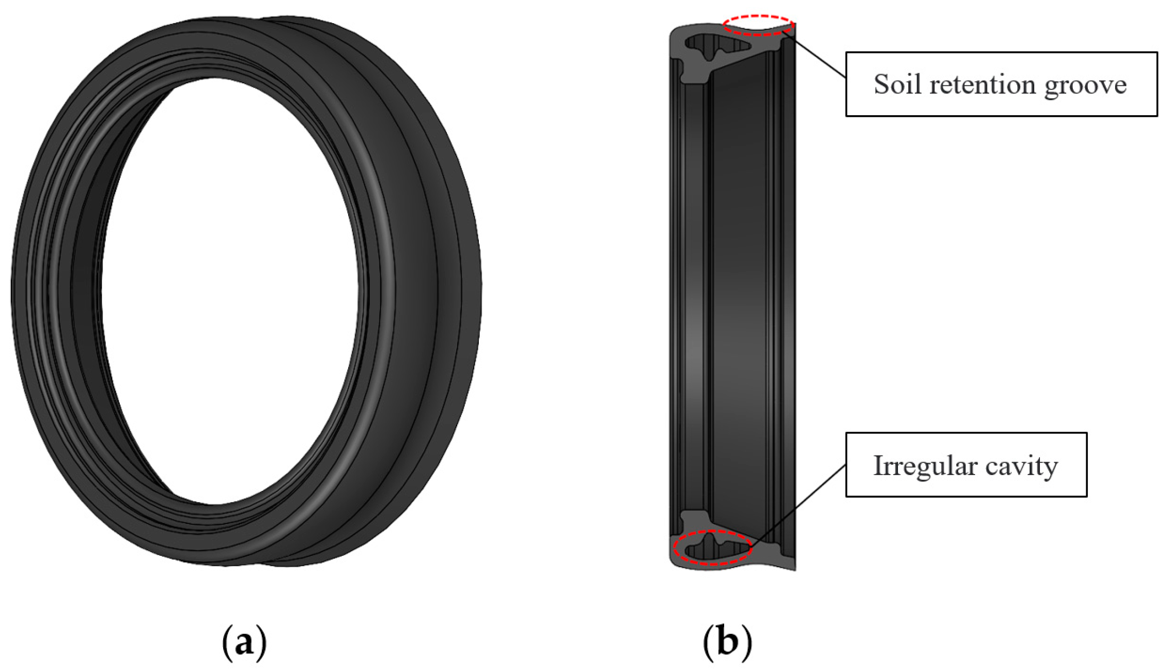
The structure of the gauge wheel with the irregular cavity designed in this paper is shown in Figure 2. The gauge wheel created a soil retention groove in the wheel by reducing the inner radius. In addition, the interior of the gauge wheel contained the irregular cavity.
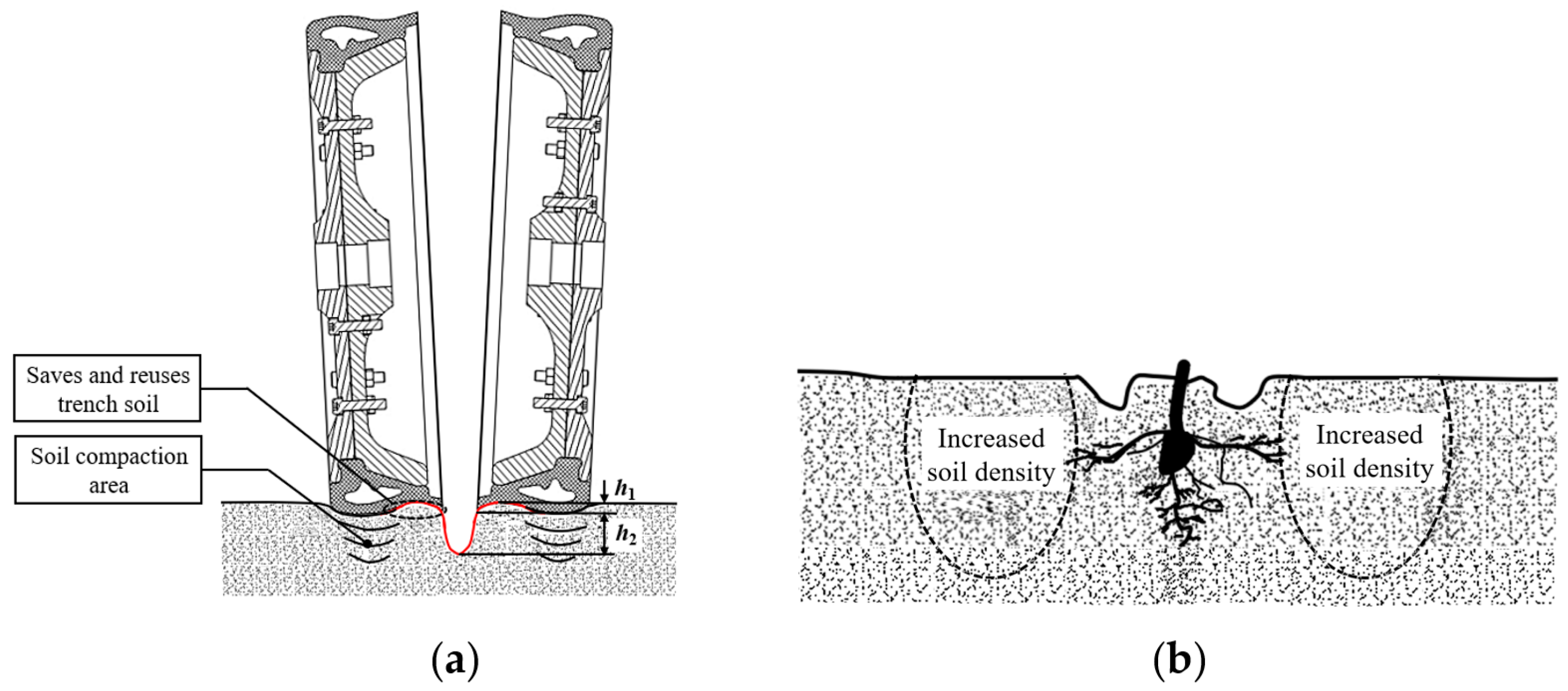
During the operation of the planting unit, the double-disk opener pressed into the soil layer, and the outer side of the gauge wheel was in contact with the ground and compacting it (Figure 3). The double-disk opener cut through the soil and pushed the soil to both sides to form a V-shaped furrow with a depth of h2 (Figure 3a). The soil pushed to both sides would enter the soil retention groove of the gauge wheel. The irregular cavity made the outer side of the gauge wheel more susceptible to deformation, which could squeeze the soil under the wheel toward the inner side of the wheel. The soil compression of the disk opener and the gauge wheel created ridges of h1 height on both sides of the furrow. The soil retention groove also avoided the furrow sidewall compaction by the gauge wheel, which was beneficial for the roots of the seedlings to grow evenly in all directions (Figure 3b). Sidewall compaction tended to cause hatchet roots or mohawk toots because the seedling roots grew along the sidewall before they actually penetrated the compacted sidewall.
2.2. Structure Parameters
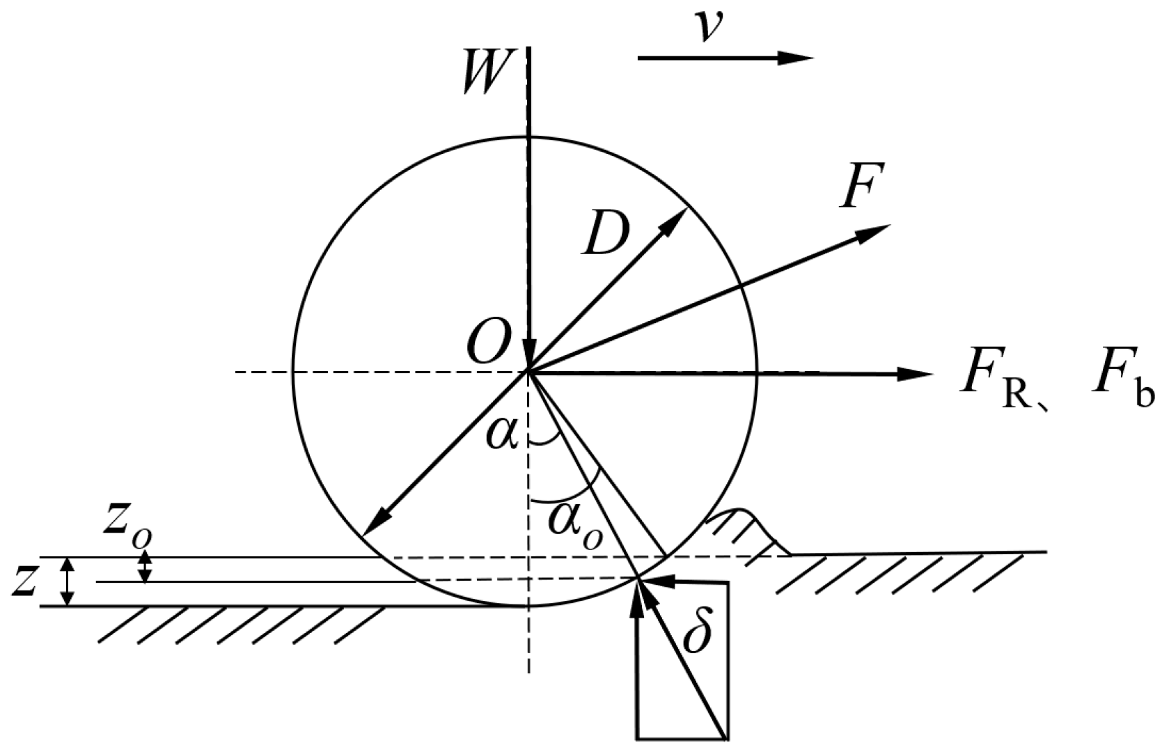
As shown in Figure 4, the gauge wheel compacted and pushed the soil when it rolled. The structural parameters of the gauge wheel affected energy consumption, soil compaction and soil subsidence depth. The compaction force FR of the gauge wheel on the soil was directly related to soil subsidence depth z [25]. The pushing force Fb of the gauge wheel on the soil pushed the soil, which increased the operational resistance of the planting unit. The compaction force FR of the gauge wheel on the soil during the operation of the planting unit can be described as follows:
where: FR is the compaction force of the gauge wheel on the soil, N; K is the inelastic deformation modulus; kc is the cohesion deformation modulus of soil, N·cm−(n+1); is the soil friction deformation modulus, N·cm−(n+2); B is the width of the gauge wheel, mm; D is the outer diameter of the gauge wheel, mm; n is the subsidence index; z is the soil subsidence depth, mm; and W is the load in the vertical direction of the gauge wheel (including the mass of the gauge wheel).
The pushing force Fb of the gauge wheel on the soil can be described as follows:
where: is the angle of internal friction of the soil, °; c is the coefficient of cohesion; Nc, Nr are the soil carrying capacity coefficients; and is the soil density, g·cm−3.
It can be seen from the above analysis that larger diameter and width can reduce the downward pressure of the gauge wheel on the soil and soil subsidence depth. However, excessive width increases pushing resistance and energy consumption. Based on the actual operation situation and experience, the outer diameter of the gauge wheel D was 500 mm and the width of the wheel B was 115 mm.
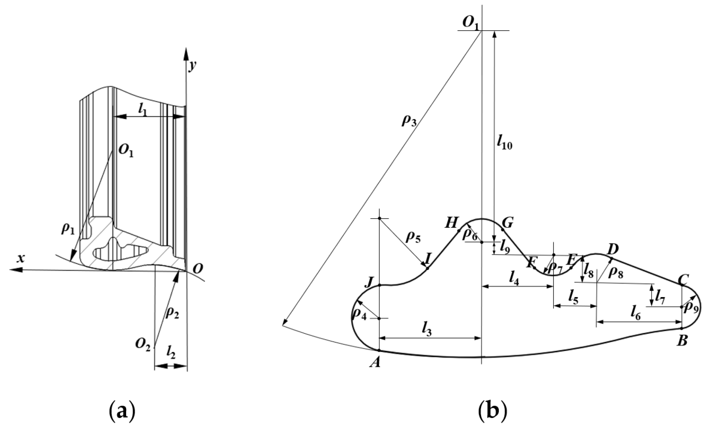
In this paper, styrene-butadiene rubber was selected as the material for the gauge wheel. The outer profile of the gauge wheel was mainly composed of circular arcs at both ends (Figure 5a): ρ1 = 108 mm, ρ2 = 66 mm, l1 = 80 mm, l2 = 36 mm. The irregular cavity improved the elasticity of the gauge wheel. The dimensions of the cross section of the gauge wheel are shown in Figure 5b. was the equidistant curve of the contour curve of the gauge wheel. The thickness of the gauge wheel was 10 mm. and could reduce stress concentration: ρ4 = 4.8 mm, ρ9 = 2.8 mm, l3 = 17 mm, l6 = 18.7 mm and l7 = 1.9 mm. The radius of was larger than the radius of , which made the outer side of the gauge wheel more prone to deformation and generated a squeezing force to the inner side of the wheel. , , and constituted the ribs of the gauge wheel, which helped to increase the strength of the gauge wheel and avoided the distortion deformation due to excessive compression or uneven stress of the gauge wheel.
2.3. ABAQUS Simulation Analysis
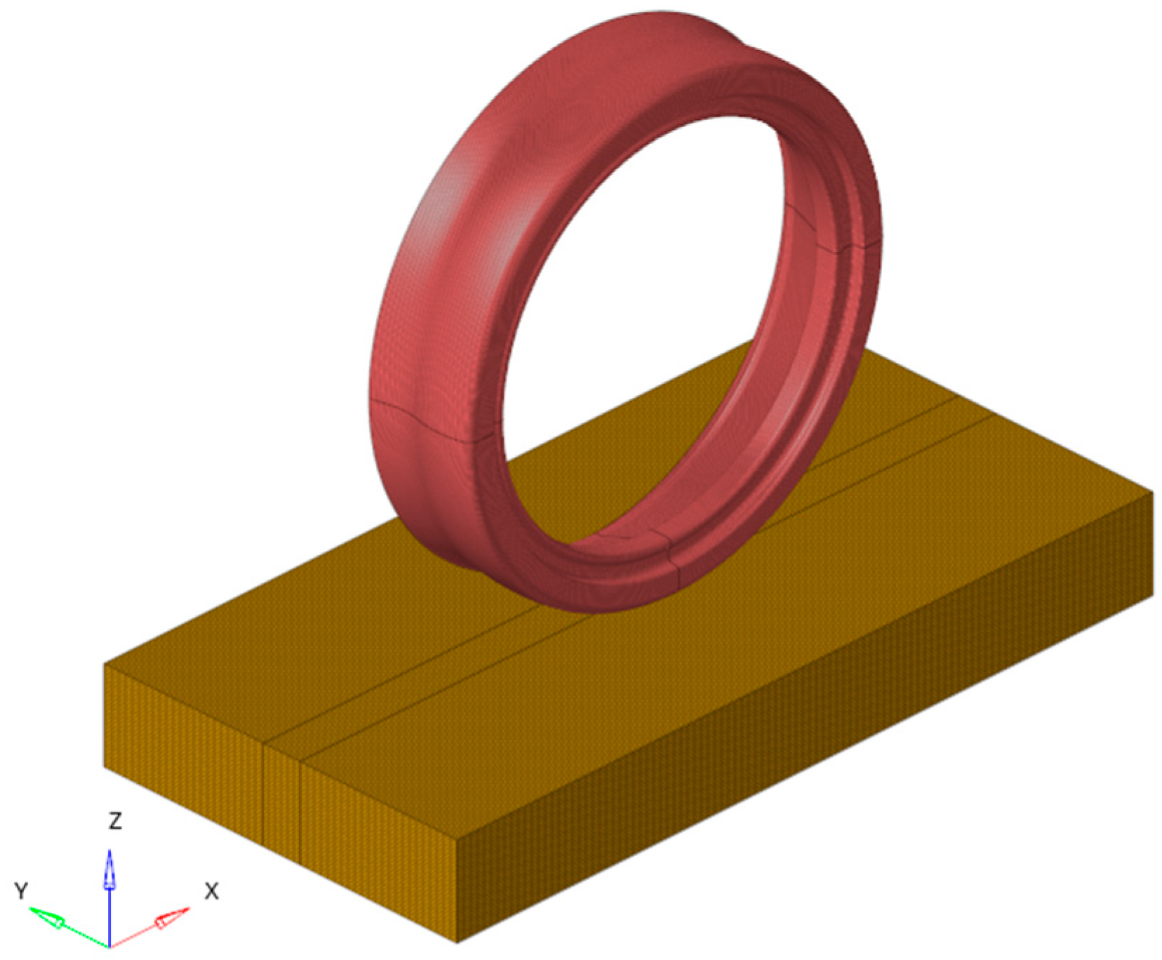
The finite element contact model between the irregular cavity gauge wheel and the soil was established by ABAQUS 2016 software, as shown in Figure 6. The Drucker–Prager model was used to establish the soil model according to the characteristics of chernozem on agricultural land in the northeast, and the parameters of the soil model [26] are shown in Table 1. The material used for the gauge wheel was styrene-butadiene rubber, and its parameters are shown in Table 2. The Mooney–Rivlin model was used to model the gauge wheel, and the material properties C10 = 0.65 MPa and C01 = 0.167 MPa were determined by uniaxial tensile testing [36]. The friction factor between the gauge wheel and the soil was set to 0.42 [37,38]. The grid element types of the gauge wheel and the soil were both linear reduced integral elements (C3D8R). The soil model was gridded by the structured method and the gauge wheel model was gridded by the sweep medial axis method. A vertical load of 510 N was applied to the gauge wheel to explore the effect and deformation variation of the gauge wheel on the ground when the force of the planting unit on the ground was maximum.
2.4. Experimental Design
2.4.1. Soil Bin Experiments
The experiment was carried out in the indoor soil bin, Jilin Agricultural Machinery Research Institute (Changchun, China). The experiments lasted from 21 to 29 September 2022. The experiments were carried out to compare the performance of the traditional gauge wheel with an oval-shaped cavity and the gauge wheel with the irregular cavity in environments with different soil moisture contents. The length of the soil bin was 50 m, width 5 m and depth 2 m. The soil type was chernozem, which was consistent with the soil type in the field in the northeast. The main experiment equipment was two planting units and a testing vehicle in soil bin. The steady working speed of the vehicle was 3.6 km·h−1. The 20 m velocity stabilization area was selected as the data acquisition area.
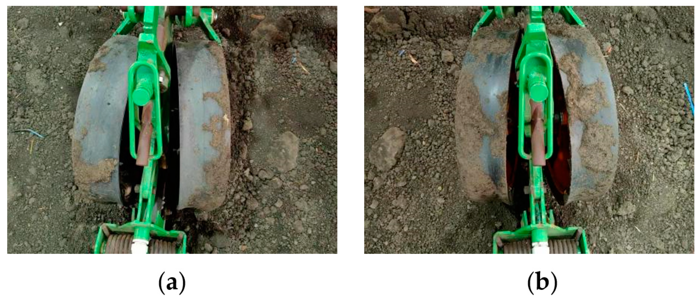
The gauge wheels with the irregular cavity and the traditional gauge wheels with the oval-shaped cavity were installed on the planting unit before the experiment (Figure 7). The traditional gauge wheel used in the experiments was made of styrene-butadiene rubber with a diameter of 500 mm and a width of 115 mm. The soil moisture content was set to 20%, 24% and 28%. For all experiments, the average working speed was 3.6 km·h−1 and the target planting depth was 70 mm. The pressure of the planting unit on the ground was 1020 N by adding bob weight to the planting unit. Each treatment was performed three times to reduce error.
To ensure the accuracy of the experiments, the soil in the soil bin needed to be rototilled, graded and suppressed before each experiment. Each experiment ensured the soil bulk density at 0–100 mm was 1.160 ± 0.116 g∙cm−3 and the soil compaction was 4.200 ± 0.420 kg∙cm−2. The soil in the trough was irrigated one week before the experiment and covered with plastic film to ensure that the moisture content in the soil bin met the requirements of the experiment. The soil moisture tester (Model TDR-300, American SPECTRUM, Changchun, China) was used to measure the soil moisture content in the soil bin to ensure the error was within 10%.
2.4.2. Field Experiments
Field experiments were carried out in Jilin Province (120°10′ E, 44°10′ N) to explore the performance of the planting unit installed with the irregular cavity gauge wheel under different operating parameters. The experiments lasted from 20 to 26 October 2022. The average temperature during the experiment was 19.8–22.1 °C. The soil type of the experimental field was chernozem, and the soil parameters are shown in Table 3.
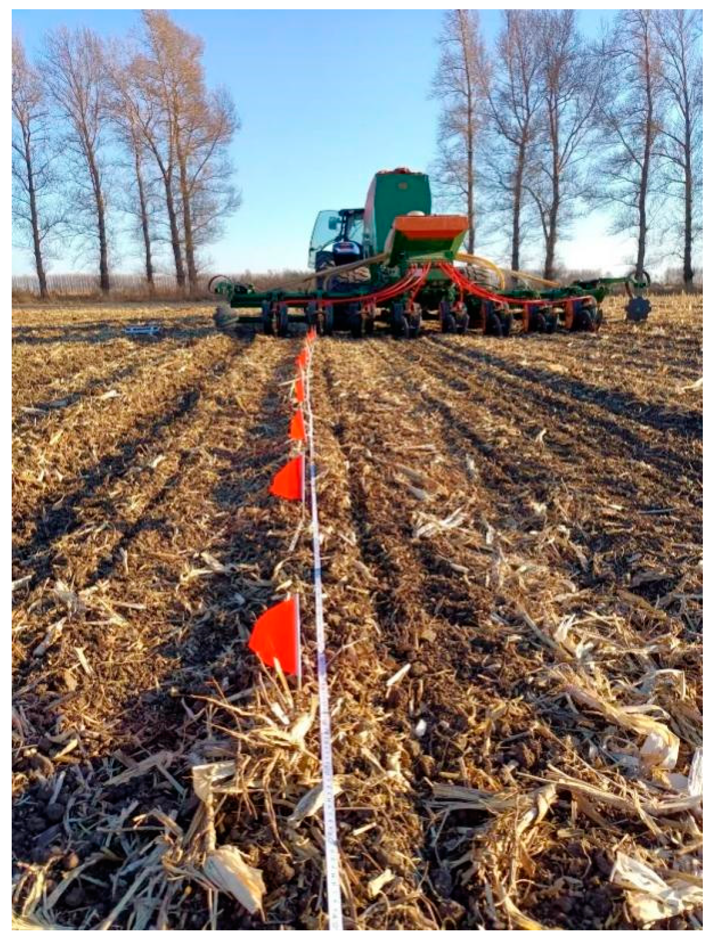
The environment of the field experiments and the planter used for the experiment are shown in Figure 8. The planter was a corn pneumatic sowing machine manufactured by the Agricultural Machinery Institute of Jilin Province. The downforce of the planting unit on the ground was changed by adjusting the pressure of the hydraulic cylinder. Each experimental area needed to be divided into an acceleration zone, stabilization zone and deceleration zone to ensure the accuracy of the measurement. The total length of each experimental area was 60 m, in which the acceleration zone and deceleration zone were 20 m each, and the middle 20 m was the working stability zone for measuring the experimental indicators. The working speed, downforce and planting depth were selected as the experimental factors. The experimental factors and levels are shown in Table 4.
2.4.3. Experimental Indicators
- Measurement of the mass of adhering soil
The soil adhered to the gauge wheel was collected, bagged, and labeled. The soil in the plastic bag was weighed with an electronic balance. Each experiment was repeated 3 times to ensure the accuracy of the experimental results, and the mean value was taken as the result of the experiment.
In this study, the viscosity reduction rate was used to evaluate the viscosity reduction effect of the irregular cavity gauge wheel compared with the traditional gauge wheel.
where R is viscosity reduction rate, %; Mi is soil adhesion of the traditional gauge wheel, g; and Ma is soil adhesion of the gauge wheel with irregular cavity, g.
- 2.
- Measurement of the shape of the seed furrow and the firmness of the sidewalls
The soil coverer of the planting unit was dismantled to observe the shape of the furrow before the experiment. A self-made profilometer was used to measure the shape of the furrow. The profilometer was placed perpendicular to the ground at the center of the seed furrow to measure the shape of the seed furrow. The profile formed at the upper end of the steels was the shape of the seed furrow when the profiling steels slid freely onto the surface of the seed furrow. The furrow shape of the seed furrow is depicted in another paper [39].
In each treatment, the soil compaction at 0–100 mm on the furrow sidewall was measured by a soil compactness meter (Model SC-900, American SPECTRUM, Changchun, China) and the interval between sampling points was 2 m. The results of each experiment measurement were averaged.
- 3.
- Measurement of the consistency of planting depth
The coefficient of variation of planting depth was used to evaluate the consistency of planting depth [29]. After the end of the experiment, the data of 20 sampling points were collected continuously at an interval of 1 m in the stable working area. The sown seeds were exposed by manual digging and the real seedling depth was the height measured from seed to field covering surface. The coefficient of variation of planting depth was calculated as follows:
where Vh is the coefficient of variation of planting depth, %; Sh is the standard deviation of planting depths, cm; is the mean value of planting depth, cm; and hi is the ith value of planting depth, cm.
3. Results and Analysis
3.1. Simulation Results
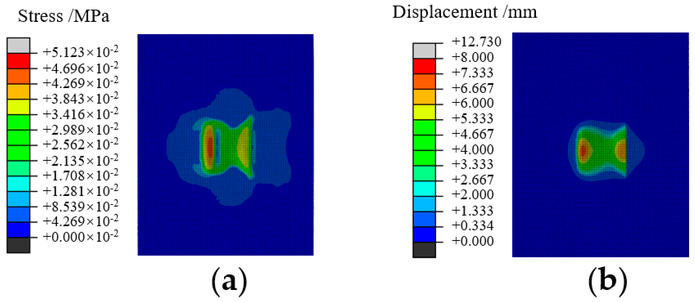
The stress and strain distribution of the soil in the contact area is shown in Figure 9. Figure 9a shows that the maximum stress in the interaction between the irregular cavity gauge wheel and the soil was distributed on the outside of the gauge wheel. The stress distribution on the inside of the irregular cavity gauge wheel was significantly lower than on the outside, which avoided compacting the furrow sidewalls. The irregular cavity gauge wheel generated a lateral stress on the soil due to the structural characteristics of the shaped cavity and the additional load. The lateral stress was conducive to the construction of a structurally stable seed furrow. As can be seen from Figure 9b, the soil was displaced in the vertical direction under stress. The largest soil subsidence occurred on the outside of the gauge wheel, and the subsidence range was 2.667–8.000 mm.
3.2. The Analysis of Soil Bin Experiments
3.2.1. Mass of Adhering Soil
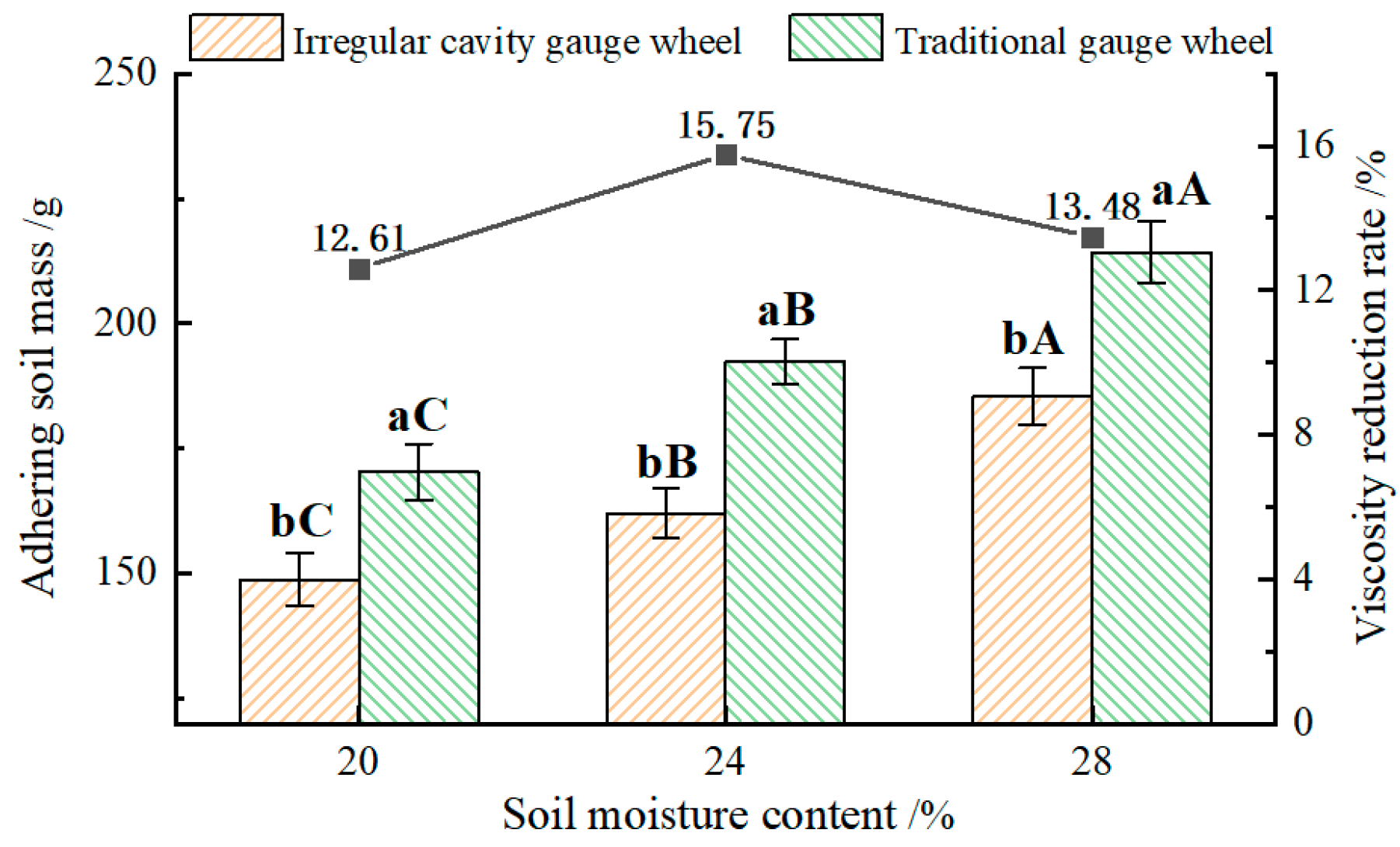
The mass of adhering soil for the two types of gauge wheels under different experimental conditions is shown in Figure 10. The soil adhesion mass of the two types of gauge wheels increased significantly with the increase in soil moisture content when the downforce of the planting unit on the ground and the furrow depth were constant. The soil adhesion mass of the irregular cavity gauge wheel was significantly lower than that of the traditional gauge wheel at the same soil moisture content, and the viscosity reduction rate was not less than 12.61%.
As can be seen from the experimental results, the irregular cavity structure increased the elasticity of the gauge wheel, which effectively reduced the adhesion of the wheel to the soil in different soil conditions. The reduced adhesion of the gauge wheel to the soil was beneficial to reduce the energy consumption of the planter and improve the consistency of sowing depth.
3.2.2. Profile of the Seed Furrow
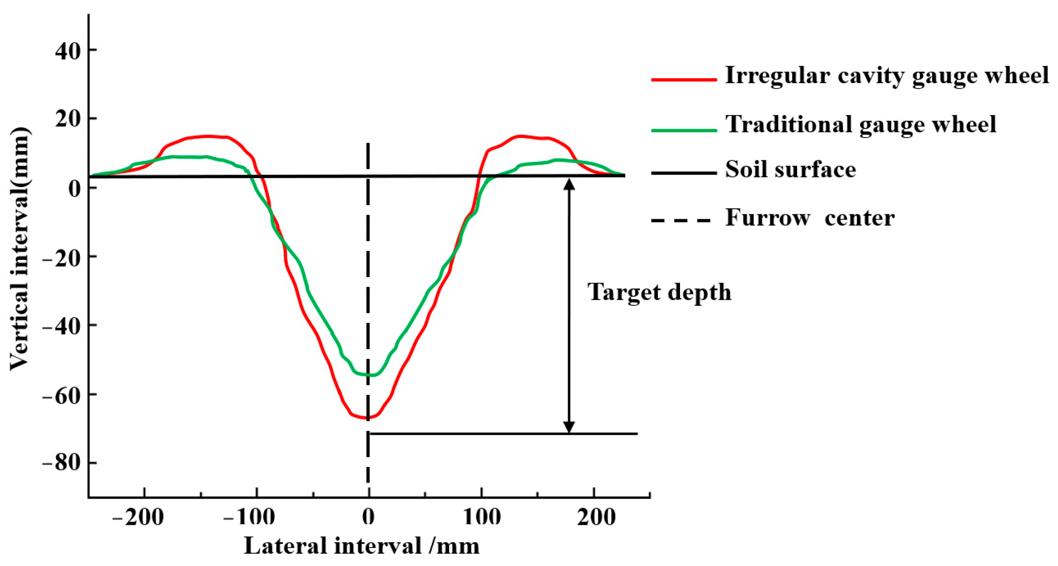
The shape of the seed furrow was mainly formed by the mutual extrusion of the gauge wheel and the double-disk opener. The cross-sectional profile of the furrow constructed by different gauge wheels is shown in Figure 11. Compared with gauge wheels with an irregular cavity, the seed furrows constructed by traditional gauge wheels had a larger width and more backfill soil. Compared with traditional gauge wheels, the seed furrows constructed by irregular cavity gauge wheels had a smaller width and less backfill soil.
The traditional gauge wheel had greater adhesion to the soil. Excessive soil on the wheels caused the actual furrow depth of the seeder to be lower than the target furrow depth. In addition, the traditional gauge wheel had a flat profile, which results in less soil on both sides of the seed furrow. The irregular cavity gauge wheel had less adhesion to the soil. Less soil on the wheel made the actual furrow depth of the planter being closer to the target furrow depth. The irregular cavity promoted the soil flow towards the seed furrow. The seed furrows constructed from irregular cavity gauge wheels formed a raised soil layer on both sides due to the soil retention groove of the gauge wheel and store the soil. The raised soil layer was conducive for the soil covering device to cover the seed with soil.
3.2.3. Soil Compaction of the Seed Furrow Sidewall
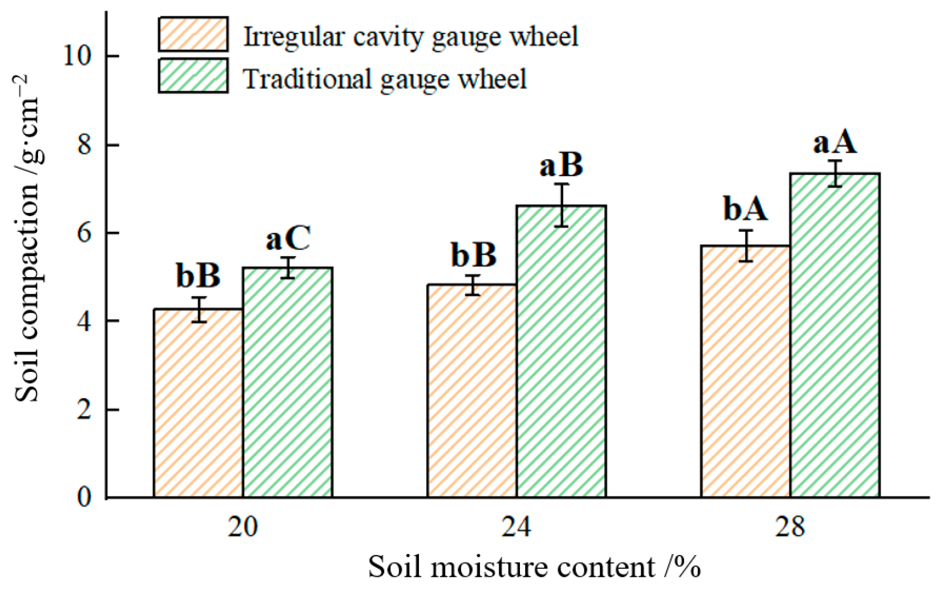
Soil compaction at 0–100 mm of the furrow sidewalls constructed with two types of gauge wheels at different soil moisture contents is shown in Figure 12. The soil moisture content had a significant effect on the soil compaction of the seed furrow sidewalls constructed by the traditional gauge wheel, and the soil compaction of the seed furrow sidewalls increased with the increase in soil moisture content. The difference in soil compaction of the seed furrow sidewalls constructed by the irregular cavity gauge wheel was not significant when the soil moisture content was 20% and 24%, but it was significantly lower when the soil moisture content was 28%. At the same soil moisture content, the soil compaction of the seed furrow sidewalls constructed by the traditional gauge wheel was significantly higher than that of the irregular cavity gauge wheel. Compared with the traditional gauge wheel, the soil compaction of the sidewalls of the seed furrow constructed by the irregular cavity gauge wheel decreased by 18.16%, 27.14% and 22.23%, respectively.
Traditional gauge wheels were compacted directly on both sides of the furrow during operation, which resulted in sidewall compaction. The soil compaction of the seed furrow sidewalls constructed by the irregular cavity gauge wheel was lower, which is consistent with the results of the simulation experiments. The irregular cavity gauge wheel did not directly compact the soil on the sidewalls of the furrows because of the soil retention groove.
3.3. Field Experiments
A three-factor and three-level test scheme was designed according to the Box–Behnken design (BBD) in Design-Expert 8.0 software. The mass of adhering soil and the consistency of planting depth were used as evaluation indicators. The experiment plan and results are shown in Table 5.
3.3.1. Mass of Adhering Soil
The results of soil adhesion mass were analyzed by variance, and the results are shown in Table 6. Regression analysis of the experimental data was performed using Design-Expert 8.0 software and a multiple regression was fitted. After removing the non-significant terms, the regression equation of soil adhesion mass was obtained.
where Y1 is the mass of adhering soil, g; X1 is the downforce, N; X2 is the working speed, km·h−1; and X3 is the planting depth, mm.
As can be seen from Table 6, the regression model for soil adhesion mass was highly significant (p < 0.01) and the lack-of-fit term of the model was non-significant. The experimental results showed that the regression model could accurately reflect the relationship between working speed, downforce, planting depth and the soil adhesion mass to the gauge wheel. According to the regression coefficients of the model factors, the effects of factors on the soil adhesion mass were ordered as follows: working speed, downforce, and planting depth.
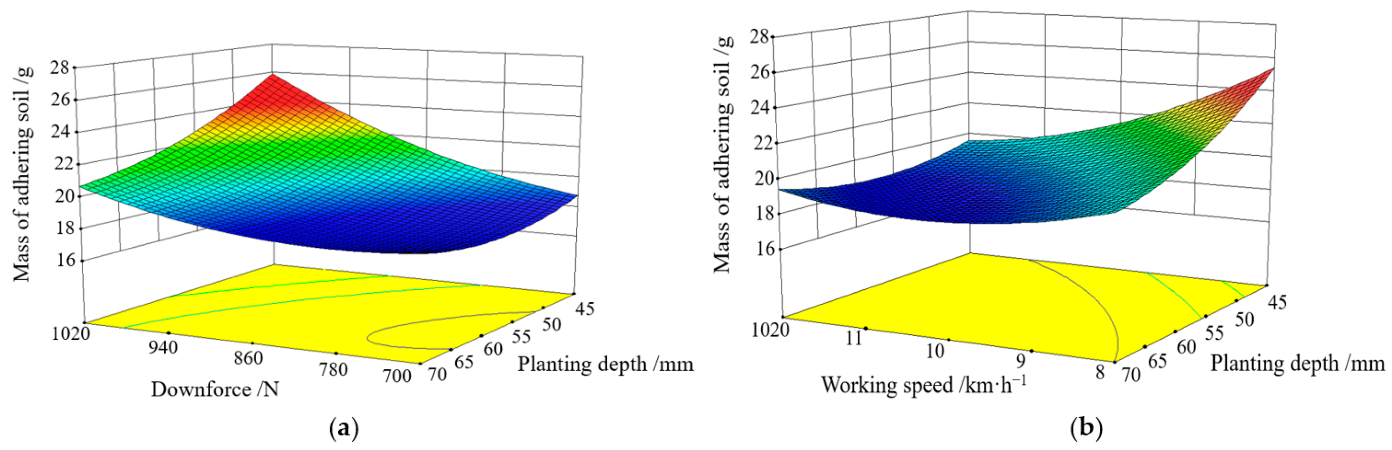
Based on the obtained quadratic regression model, the response surfaces of the three factors of working speed, downforce, and planting depth with different interaction levels on the soil adhesion mass to the gauge wheel were plotted. The interaction term between working speed and downforce was not analyzed because the interaction was not significant in the model. The response surface of soil adhesion mass is shown in Figure 13.
As can be seen from Figure 13a, the soil adhesion mass increased with the increase in the downforce at a certain working speed. When the downforce of the planter on the ground increased, the gauge wheel was in closer contact with the soil and the contact area was larger, which made the soil adhesion mass larger. This result was consistent with the soil bin experimental results. The soil adhesion mass decreased with the increase in planting depth. When the planting depth increased, the resistance of the planter from the vertical direction of the ground increased, and the downforce of the gauge wheel to the ground decreased, which reduced the soil adhesion mass of the gauge wheel. It can be seen from Figure 13b that when the downforce of the planter on the ground was certain, the soil adhesion mass gradually decreased with the increase in working speed. The resistance from the vertical direction of the ground increased as the working speed increased, which reduced the downforce of the planter, and the soil adhesion mass gradually decreased.
3.3.2. Consistency of Planting Depth
The results of the coefficient of variation of planting depth were analyzed by variance analysis and the results are shown in Table 7. Regression analysis of the experimental data was performed using Design-Expert 8.0 software and a multiple regression was fitted. After removing the non-significant terms, the regression equation of the coefficient of variation of planting depth was obtained:
where Y2 is the coefficient of variation of planting depth, %; X1 is the downforce, N; X2 is the working speed, km·h−1; and X3 is the planting depth, mm.
As can be seen from Table 7, the regression model for the coefficient of variation of planting depth was highly significant (p < 0.01) and the lack-of-fit term of the model was non-significant. The experimental results showed that the regression model obtained was highly reliable. According to the regression coefficients of the model factors, the effects of factors on the coefficient of variation of planting depth was ordered as follows: downforce, planting depth, and working speed.
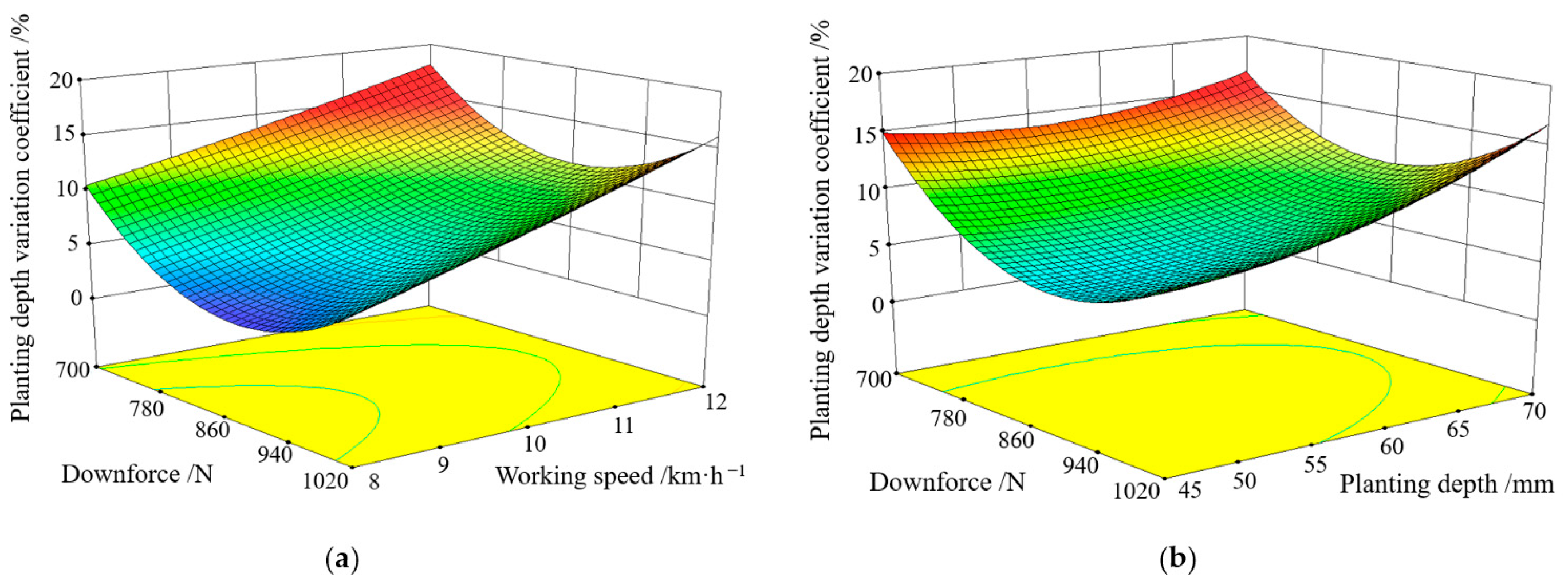
Based on the obtained quadratic regression model, the response surfaces of the three factors of working speed, downforce and planting depth with different interaction levels on the coefficient of variation of planting depth were plotted (Figure 14). The interaction term between downforce and planting depth was not analyzed because the interaction was not significant in the model.
As can be seen from Figure 14a, the coefficient of variation of planting depth decreased and then increased with the increase in the downforce at a certain planting depth. When the downforce was increased, the gauge wheel was in close contact with the soil and the operation was stable, which reduced the coefficient of variation of planting depth. However, when the downforce of the planter on the ground was too high, the gauge wheel adhered to more soil, which reduced the coefficient of variation of planting depth. The coefficient of variation of planting depth increased with the increase in working speed. The frictional resistance from the ground during planter operation increased with the increase in working speed, which reduced the stability of the planter, increased the coefficient of variation of planting depth and reduced the consistency of planting depth. It can be seen from Figure 14b that the coefficient of variation of planting depth gradually increased with the increase in planting depth when the working speed of the planter was 10 km·h−1. As the planting depth increased, the resistance of the planter from the vertical direction of the ground increased and the downforce of the planter on the ground decreased, which made the seeding operation less stable and the coefficient of variation of planting depth increased.
The lower the mass of the soil adhering to the gauge wheel and the lower the coefficient of variation of the planting depth, the better the performance of the planter. To obtain the optimal performance of the planter, it was necessary to optimize the experimental parameters (downforce, working speed, planting depth) according to the experimental results and regression models. The objective function was:
The objective function was optimized and solved to obtain a set of parameter combinations with high confidence. The working speed was easily affected by the complex ground conditions in the field and it was difficult to ensure its accuracy, and the planter could not achieve high precision control on the downforce. Taking the above into account, the optimal combination of parameters was finally selected as follows: the downforce of the planter was 844 N, the working speed of the planter was 8 km·h−1 and the planting depth was 65 mm. Under this parameter combination, the mass of the soil adhering to the planter’s gauge wheel was 118.56 g, and the coefficient of variation of planting depth was 5.01%. Verification tests were carried out according to the combination of optimal scheme parameters to verify the accuracy of the optimization parameters. The planting was repeated three times with the optimum combination of operating parameters and the results were averaged.
In the verification test, the mass of the soil adhering to the planter’s gauge wheel was 123.65 g and the coefficient of variation of planting depth was 5.35%. The relative error with the software optimization results was 4.3% and 6.8%, indicating that the software optimization parameter values were credible.
4. Conclusions
In this study, an elastic gauge wheel with soil retention groove and irregular cavity was designed to reduce the soil adhesion and improve the seed furrow structure. The conclusions are:
- (1)
- The results of the soil bin experiments showed that that the gauge wheel with the irregular cavity adhered to lower soil and better seed furrow structure. The viscosity reduction rate of the gauge wheel with the irregular cavity was not less than 12.61%. Compared with the traditional gauge wheel, the seed furrow constructed by the gauge wheel with the irregular cavity had ridges on both sides and less backfill soil, and the soil compaction of sidewalls decreased by 18.16%. This type of furrow was more conducive to improving the consistency of planting depth and allowing the roots of the seeds to grow evenly in all directions.
- (2)
- The results of the field experiments showed that the planting unit had the best performance when the downforce of the planter was 844 N, the working speed of the planter was 8 km·h−1 and the planting depth was 65 mm. The verification test of the optimal operating parameters showed that the soil adhesion mass of the gauge wheel was 123.65 g and the coefficient of variation of the planting depth was 5.35%.
Author Contributions
Conceptualization, H.L. and X.X.; methodology, H.L. and D.H.; software, X.X. and L.C.; validation, L.C. and R.R.; investigation, H.L. and D.H.; resources, D.H.; visualization, L.C. and R.R. All authors have read and agreed to the published version of the manuscript.
Funding
This research was financially supported by the Science and Technology Development Program of Jilin Province, grant 20220508113RC.
Institutional Review Board Statement
Not applicable.
Data Availability Statement
Not applicable.
Conflicts of Interest
The authors declare that there are no conflicts of interest.
References
- Wang, J.; Qi, X.; Xu, C.; Wang, Z.; Tang, H. Design Evaluation and Performance Analysis of the Inside-Filling Air-Assisted High-Speed Precision Maize Seed-Metering Device. Sustainability 2021, 13, 5483. [Google Scholar] [CrossRef]
- Yang, L.; Yan, B.; Zhang, D.; Zhang, T.; Wang, Y.; Cui, T. Research Progress on Precision Planting Technology of Maize. Trans. Chin. Soc. Agric. Mach. 2016, 47, 38–48. [Google Scholar] [CrossRef]
- Li, M.; Xia, X.; Zhu, L.; Zhou, R.; Huang, D. Intelligent planting depth regulation system based on Flex sensor and Mamdani fuzzy model for a no-till planter. Int. J. Agric. Biol. Eng. 2021, 14, 145–152. [Google Scholar] [CrossRef]
- Dhillon, G.; Baarda, L.; Gretzinger, M.; Coles, K. Effect of precision planting and seeding rates on canola plant density and seed yield in southern Alberta. Can. J. Plant Sci. 2022, 10, 698–709. [Google Scholar] [CrossRef]
- Mourtzinis, S.; Roth, A.; Gaska, J.; Conley, S. Planting method and seeding rate effect on whole and partitioned soybean yield. Agrosystems Geosci. Environ. 2021, 4, e20208. [Google Scholar] [CrossRef]
- Zhang, J.; Yun, G.; Guo, F.; Li, X.; Wan, S. Research progress on the mechanism of improving peanut yield by single-seed precision sowing. J. Integr. Agric. 2020, 19, 1919–1927. [Google Scholar] [CrossRef]
- Lamichhane, J.; Soltani, E. Sowing and seedbed management methods to improve establishment and yield of maize, rice and wheat across drought-prone regions: A review. J. Agric. Food Res. 2020, 2, 100089. [Google Scholar] [CrossRef]
- Ozmerzi, A.; Karayel, D.; Topakci, M. Effect of planting depth on precision seeder uniformity. Biosyst. Eng. 2002, 82, 227–230. [Google Scholar] [CrossRef]
- Sharipov, G.; Paraforos, D.; Griepentrog, H. Implementation of a magnetorheological damper on a no-till seeding assembly for optimising seeding depth. Comput. Electron. Agric. 2018, 150, 465–475. [Google Scholar] [CrossRef]
- Li, B. Agricultural Mechanics; China Agriculture Press: Beijing, China, 2003; pp. 66–68. [Google Scholar]
- Zhao, S.; Yang, L.; Zhang, X.; Hou, L.; Yuan, W.; Yang, Y. Design and Experiment of Zigzag Opener for Double-row No-tillage Seeding on Soybean Ridge. Trans. Chin. Soc. Agric. Mach. 2022, 53, 74–84. [Google Scholar] [CrossRef]
- Wang, J.; Wen, N.; Liu, Z.; Zhou, W.; Tang, H.; Wang, Q.; Wang, J. Coupled Bionic Design of Liquid Fertilizer Deep Application Type Opener Based on Sturgeon Streamline to Enhance Opening Performance in Cold Soils of Northeast China. Agriculture 2022, 12, 615. [Google Scholar] [CrossRef]
- Munir, M.; Iqbal, M.; Miran, S. Evaluation of three seed furrow openers mounted on a zone disk tiller drill for residue management, soil physical properties and crop parameters. Pak. J. Agric. Sci. 2013, 49, 349–355. [Google Scholar] [CrossRef]
- Ferreira, C.; Tormena, C.; Severiano, E.; Nunes, M.; Menezes, C.; Antille, D.; Preto, V. Effectiveness of narrow tyne and double-discs openers to overcome shallow compaction and improve soybean yield in long-term no-tillage soil. Soil Tillage Res. 2023, 227, 105622. [Google Scholar] [CrossRef]
- Zhou, W.; Ni, X.; Song, K.; Wen, N.; Song, C.; Sun, X.; Wang, Y.; Wang, J.; Wang, Q.; Tang, H. Bionic Design of Furrow Opener Based on Muskrat Claw-Toe Structure to Improve the Operating Performance of Deep Application of Liquid Fertilizer in Paddy Fields in Cold Region of China. Agriculture 2023, 13, 254. [Google Scholar] [CrossRef]
- Zhang, R.; Cui, T.; Han, D.; Zhang, D.; Li, K.; Yin, X.; Wang, Y.; He, X.; Yang, L. Design of depth-control planting unit with single-side gauge wheel for no-till maize precision planter. Int. J. Agric. Biol. Eng. 2017, 9, 56–64. [Google Scholar] [CrossRef]
- Karayel, D.; Ozmerzi, A. Evaluation of Three Depth-Control Components on Seed Placement Accuracy and Emergence for a Precision Planter. Appl. Eng. Agric. 2008, 24, 271–276. [Google Scholar] [CrossRef]
- Cui, T.; Zhang, D.; Yang, L.; Gao, N. Design and experiment of collocated-copying and semi-low-height planting-unit for corn precision seeder. Trans. Chin. Soc. Agric. Eng. 2012, 28 (Suppl. S2), 18–23. [Google Scholar] [CrossRef]
- Vamerali, T.; Bertocco, M.; Sartori, L. Effects of a new wide-sweep opener for no-till planter on seed zone properties and root establishment in maize (Zea mays, L.): A comparison with double-disk opener. Soil Tillage Res. 2006, 89, 196–209. [Google Scholar] [CrossRef]
- Zhao, Y.; Chen, L.; Li, J.; Chu, C.; Huang, F.; Che, J.; Zhang, C.; Li, C. Research on the definition of soil types in typical black soil regions of Northeast China. Sci. Soil Water Conserv. 2020, 18, 123–129. [Google Scholar] [CrossRef]
- Zhang, Q.; Qin, W.; Cao, W.; Jiao, J.; Yin, Z.; Xu, H. Response of erosion reduction effect of typical soil and water conservation measures in cropland to rainfall and slope gradient changes and their applicable range in the Chinese Mollisols Region, Northeast China. Int. Soil Water Conserv. Res. 2023, 11, 251–262. [Google Scholar] [CrossRef]
- Zhao, J.; Wang, X.; Lu, Y.; Wei, Y.; Guo, M.; Fu, J. Biomimetic earthworm dynamic soil looser for improving soybean emergence rate in cold and arid regions. Int. J. Agric. Biol. Eng. 2021, 14, 22–31. [Google Scholar] [CrossRef]
- Liu, H.; Zhao, S.; Tan, H.; Yang, Y.; Zhang, X. Investigation on Press Device in Reducing Adhesion and Resistance Based on Scrape and Vibration Principle. Trans. Chin. Soc. Agric. Mach. 2018, 49, 86–92. [Google Scholar] [CrossRef]
- Tong, J.; Zhang, Q.; Chang, Y.; Li, M.; Zhang, L.; Liu, X. Finite Element Analysis and Experimental Verification of Bionic Press Roller in Reducing Adhesion and Resistance. Trans. Chin. Soc. Agric. Mach. 2014, 45, 85–92. [Google Scholar] [CrossRef]
- Tong, J.; Zhang, Q.; Chang, Y.; Chen, d.; Dong, W.; Zhang, L. Experiments on ribbed bionic ballast rollers for viscosity reduction and resistance reduction. Trans. Chin. Soc. Agric. Mach. 2014, 45, 135–140. [Google Scholar] [CrossRef]
- Jia, H.; Guo, H.; Guo, M.; Wang, L.; Zhao, J.; Fan, X. Analysis and experiments on finite element simulation of the performance of flexible mulchable ballast wheels for inter-row cultivators. Trans. Chin. Soc. Agric. Eng. 2015, 31, 9–16+315. [Google Scholar] [CrossRef]
- Jia, H.; Wang, W.; Zhang, J.; Luo, X.; Yao, P.; Li, Y. Design and Experiment on Reducing Soil Adhesion and Anti-slip Structure of Profiling Elastic Press Roller. Trans. Chin. Soc. Agric. Mach. 2015, 46, 20–27. [Google Scholar] [CrossRef]
- McLaughlin, N.; Campbell, A.; Owen, G. Performance of hoe and triple disc furrow openers on no-till grain drills in a fine sandy loam soil. Soil Tillage Res. 2019, 19, 104373. [Google Scholar] [CrossRef]
- Jing, H.; Zhang, D.; Wang, Y.; Yang, L.; Fan, C.; Zhao, H.; Wu, H.; Zhang, Y.; Pei, J.; Cui, T. Development and performance evaluation of an electro-hydraulic downforce control system for planter row unit. Comput. Electron. Agric. 2022, 172, 105073. [Google Scholar] [CrossRef]
- Rut, G.; Grzesiak, M.; Maksymowicz, A.; Jurczyk, B.; Rzepka, A.; Hura, K.; Grzesiak, S. Responses of a root system structure to soil compaction stress among maize (Zea mays L.) hybrids. J. Agron. Crop Sci. 2021, 208, 106–119. [Google Scholar] [CrossRef]
- Wang, X.; Wang, Q.; Li, H.; Li, W.; Niu, Q.; Chen, W. Effect of Tyre lnduced Soil Compaction on Soil Properties and Crop Root Growth under No-tillage System. Trans. Chin. Soc. Agric. Mach. 2017, 48, 168–175. [Google Scholar] [CrossRef]
- Arvidsson, J.; Bolenius, E.; Cavalieri, K. Effects of Compaction During Drilling on Yield of Sugar Beet (Beta vulgaris L.). Eur. J. Agron. 2012, 39, 44–51. [Google Scholar] [CrossRef]
- Bazzaz, M.; Hossain, A.; Timsina, J.; da Silva, J.; Nuruzzaman, M. Growth, Yield Attributes and Yield of Irrigated Spring Wheat as Influenced by Planting Depth. Open Agric. 2018, 3, 72–83. [Google Scholar] [CrossRef]
- Zhou, F.; Chen, Q.; Jin, R.; Du, L.; Li, X.; Chen, X.; Liu, X.; Yan, J.; Kong, F. Effects of Kernel Size and Seedling depth on Maize Root Growth in the Middle Sichuan Hilly Area. Chin. J. Eco-Agric. 2019, 27, 1799–1811. [Google Scholar] [CrossRef]
- Zhang, S.; Zhao, W.; Dai, F.; Song, X.; Qv, J.; Zhang, F. Simulation analysis and test on suppression operation process of ridging and film covering machine with full-film double-furrow. Trans. Chin. Soc. Agric. Eng. 2020, 36, 20–30. [Google Scholar] [CrossRef]
- Si, H.; Cai, Z. Development of static constitutive model library for soils based on ABAQUS. Rock Soil Mech. 2011, 32, 599–603. [Google Scholar] [CrossRef]
- Zuo, L.; Xiao, F. Analysis of materials coefficient of rubber Mooney-Rivlin model impacting on the axial stiffness. China Elastomerics 2008, 18, 54–56. [Google Scholar] [CrossRef]
- Ren, M.; Han, Q.; Zhang, Z. The analysis on the interaction between the rolling tire and the deformed ground based on ABAQUS/Explicit. Mod. Manuf. Eng. 2012, 387, 40–43+70. [Google Scholar] [CrossRef]
- Wang, Q.; Zhu, L.; Li, M.; Huang, D.; Jia, H. Conservation Agriculture Using Coulters: Effects of Crop Residue on Working Performance. Sustainability 2018, 10, 4099. [Google Scholar] [CrossRef] [Green Version]
Figure 1.
Structure of the planting unit: (1) double-disk opener; (2) gauge wheel arm; (3) frame; (4) depth regulator; (5) gauge wheel; (6) seed hose; (7) seed firmer; (8) press wheel.
Figure 1.
Structure of the planting unit: (1) double-disk opener; (2) gauge wheel arm; (3) frame; (4) depth regulator; (5) gauge wheel; (6) seed hose; (7) seed firmer; (8) press wheel.

Figure 2.
Structure of the irregular cavity gauge wheel: (a) structure of gauge wheel; (b) sectional drawing of gauge wheel.
Figure 2.
Structure of the irregular cavity gauge wheel: (a) structure of gauge wheel; (b) sectional drawing of gauge wheel.

Figure 3.
Working principle diagram of the irregular cavity gauge wheel: (a) the gauge wheel and the soil of the seed furrow; (b) the root growth of seedlings. Note: h1 is the height of the soil on both sides of the seed furrow, mm; h2 is the depth of the V-shaped seed furrow, mm.
Figure 3.
Working principle diagram of the irregular cavity gauge wheel: (a) the gauge wheel and the soil of the seed furrow; (b) the root growth of seedlings. Note: h1 is the height of the soil on both sides of the seed furrow, mm; h2 is the depth of the V-shaped seed furrow, mm.

Figure 4.
Schematic diagram showing hilling phenomenon in the process of gauge wheel moving. Note: W is the load in the vertical direction on the gauge wheel, N; F is the pulling force of the gauge wheel arm on the gauge wheel, N; δ is the soil reaction force per unit area of the gauge wheel, N; z is the maximum soil subsidence depth of the gauge wheel, mm; zo is the soil subsidence depth at any given moment, mm; α, αo are the circular angles corresponding to the amount of soil subsidence z, zo, °; and D is the outer diameter of the gauge wheel, mm.

Figure 5.
Cross-section dimensions of the gauge wheel: (a) outer profile of gauge wheel; (b) cavity of gauge wheel.
Figure 5.
Cross-section dimensions of the gauge wheel: (a) outer profile of gauge wheel; (b) cavity of gauge wheel.

Figure 6.
Finite element contact model of irregular cavity gauge wheel and soil.

Figure 7.
Planting unit with different gauge wheels: (a) profiling gauge wheel with irregular cavity; (b) profiling gauge wheel with symmetrical cavity.
Figure 7.
Planting unit with different gauge wheels: (a) profiling gauge wheel with irregular cavity; (b) profiling gauge wheel with symmetrical cavity.

Figure 8.
Experimental site.

Figure 9.
Simulation results of the irregular cavity gauge wheel: (a) stress distribution map of soil in contact area; (b) displacement distribution map of soil in contact area.
Figure 9.
Simulation results of the irregular cavity gauge wheel: (a) stress distribution map of soil in contact area; (b) displacement distribution map of soil in contact area.

Figure 10.
Results of soil adhesion mass. Note: The different lowercase letters indicate that the data are significantly different at the 0.05 level between different gauge wheels in the same soil moisture contents. The different capital letters indicate that the data are significantly different at the 0.05 level between the same gauge wheels in different soil water contents.

Figure 11.
Cross-sectional profile of the furrow.

Figure 12.
Results of soil compaction on the sidewalls of seed furrows. Note: The different lowercase letters indicate that the data are significantly different at the 0.05 level between different gauge wheels in the same soil moisture contents. The different capital letters indicate that the data are significantly different at the 0.05 level between the same gauge wheels in different soil water contents.

Figure 13.
Effect of interaction factors on soil adhesion mass: (a) response surface showing effects of downforce and planting depth on soil adhesion mass; (b) response surface showing effects of working speed and planting depth on soil adhesion mass.
Figure 13.
Effect of interaction factors on soil adhesion mass: (a) response surface showing effects of downforce and planting depth on soil adhesion mass; (b) response surface showing effects of working speed and planting depth on soil adhesion mass.

Figure 14.
Effect of interaction factors on planting depth variation coefficient: (a) response surface showing effects of downforce and working speed on planting depth variation coefficient; (b) response surface showing effects of downforce and planting depth on planting depth variation coefficient.


Table 1.
Soil parameters of finite element model.
| Parameters | Values |
|---|---|
| Soil density | 1155 kg·m−3 |
| Young’s modulus | 1.17 MPa |
| Poisson’s ratio | 0.35 |
| Eccentric ratio | 0.1 |
| Friction angle | 12.17° |
| Initial yield surface position | 0.0002 |
| Stress ratio | 1 |
| Cohesive force | 10 kPa |
Table 2.
Gauge wheel parameters of finite element model.
| Parameters | Values |
|---|---|
| Density | 1300 kg·m−3 |
| Young’s modulus | 4.9 MPa |
| Poisson’s ratio | 0.49 |
Table 3.
Soil parameters in the field.
| Depth of Soil Layer/mm | Volume Soil Moisture Content/% | Soil Bulk Density/g·cm−3 | Soil Compaction/g·cm−2 |
|---|---|---|---|
| 0–100 | 21.06 | 1.12 | 4.21 |
| 100–200 | 25.15 | 1.23 | 6.94 |
Table 4.
Experimental factors and levels in the field experiments.
| Levels | Factors | ||
|---|---|---|---|
| Downforce/N | Working Speed/km·h−1 | Planting Depth/mm | |
| −1 | 700 | 8 | 45 |
| 0 | 860 | 10 | 55 |
| 1 | 1020 | 12 | 70 |
Table 5.
Experimental scheme and results.
| No. | Test Factors | Evaluation Indicators | |||
|---|---|---|---|---|---|
| Downforce/N | Working Speed/km·h−1 | Planting Depth/mm | Mass of Adhering Soil/g | Coefficient of Variation of Planting Depth/% | |
| 1 | −1 | −1 | 0 | 19.00 | 10.59 |
| 2 | 1 | −1 | 0 | 25.56 | 6.04 |
| 3 | −1 | 1 | 0 | 18.60 | 18.05 |
| 4 | 1 | 1 | 0 | 22.00 | 16.06 |
| 5 | −1 | 0 | −1 | 18.92 | 8.54 |
| 6 | 1 | 0 | −1 | 25.76 | 15.04 |
| 7 | −1 | 0 | 1 | 18.64 | 16.71 |
| 8 | 1 | 0 | 1 | 20.60 | 16.52 |
| 9 | 0 | −1 | −1 | 26.04 | 3.39 |
| 10 | 0 | 1 | −1 | 19.00 | 10.42 |
| 11 | 0 | −1 | 1 | 20.60 | 6.87 |
| 12 | 0 | 1 | 1 | 18.84 | 15.59 |
| 13 | 0 | 0 | 0 | 19.68 | 7.01 |
| 14 | 0 | 0 | 0 | 18.92 | 6.73 |
| 15 | 0 | 0 | 0 | 18.56 | 5.88 |
Note: The mass of adhering soil was the actual mass of adhering soil minus 100 g.
Table 6.
Variance analysis of soil adhesion mass.
| Source of Variance | Sum of Squares | Freedom | Mean Square | F-Value | p-Value |
|---|---|---|---|---|---|
| Model | 105.54 | 9 | 11.73 | 15.62 | 0.0037 (extremely significant) |
| X1 | 43.99 | 1 | 43.99 | 58.60 | 0.0006 (extremely significant) |
| X2 | 20.35 | 1 | 20.35 | 27.11 | 0.0034 (extremely significant) |
| X3 | 15.24 | 1 | 15.24 | 20.29 | 0.0064 (extremely significant) |
| X1×2 | 2.50 | 1 | 2.50 | 3.33 | 0.1278 (non-significant) |
| X1×3 | 5.95 | 1 | 5.95 | 7.93 | 0.0373 (significant) |
| X2×3 | 6.97 | 1 | 6.97 | 9.28 | 0.0285 (significant) |
| X12 | 4.06 | 1 | 4.06 | 5.41 | 0.0676 (relatively significant) |
| X22 | 5.21 | 1 | 5.21 | 6.95 | 0.0462 (significant) |
| X32 | 2.85 | 1 | 2.85 | 3.79 | 0.1090 (non-significant) |
| Residual | 3.75 | 5 | 0.75 | ||
| Lack of fit | 3.10 | 3 | 1.03 | 3.60 | 0.2496 (non-significant) |
| Error | 0.65 | 2 | 0.33 | ||
| Total | 109.30 | 14 |
Table 7.
Variance analysis of planting depth variation coefficient.
| Source of Variance | Sum of Squares | Freedom | Mean Square | F-Value | p-Value |
|---|---|---|---|---|---|
| Model | 375.03 | 9 | 375.03 | 249.98 | 0.0001 (extremely significant) |
| X1 | 20.64 | 1 | 20.64 | 123.84 | 0.0001 (extremely significant) |
| X2 | 155.14 | 1 | 155.14 | 930.68 | 0.0001 (extremely significant) |
| X3 | 51.51 | 1 | 51.51 | 309.02 | 0.0001 (extremely significant) |
| X1×2 | 1.64 | 1 | 1.64 | 9.84 | 0.0258 (significant) |
| X1×3 | 11.19 | 1 | 11.19 | 67.12 | 0.0004 (extremely significant) |
| X2×3 | 0.024 | 1 | 0.024 | 0.14 | 0.7198 (non-significant) |
| X12 | 128.10 | 1 | 128.10 | 768.49 | 0.0001 (extremely significant) |
| X22 | 0.24 | 1 | 0.24 | 1.44 | 0.2836 (non-significant) |
| X32 | 11.60 | 1 | 11.60 | 69.58 | 0.0004 (extremely significant) |
| Residual | 0.83 | 5 | 0.17 | ||
| Lack of fit | 0.14 | 3 | 0.047 | 0.14 | 0.9305 (non-significant) |
| Error | 0.69 | 2 | 0.35 | ||
| Total | 375.86 | 14 |
Disclaimer/Publisher’s Note: The statements, opinions and data contained in all publications are solely those of the individual author(s) and contributor(s) and not of MDPI and/or the editor(s). MDPI and/or the editor(s) disclaim responsibility for any injury to people or property resulting from any ideas, methods, instructions or products referred to in the content. |
© 2023 by the authors. Licensee MDPI, Basel, Switzerland. This article is an open access article distributed under the terms and conditions of the Creative Commons Attribution (CC BY) license (https://creativecommons.org/licenses/by/4.0/).
Share and Cite
MDPI and ACS Style
Li, H.; Xia, X.; Chen, L.; Ran, R.; Huang, D. Elastic Gauge Wheel with Irregular Cavity for Improving Seed Furrow Structure and Seeding Quality. Agriculture 2023, 13, 1438. https://doi.org/10.3390/agriculture13071438
AMA Style
Li H, Xia X, Chen L, Ran R, Huang D. Elastic Gauge Wheel with Irregular Cavity for Improving Seed Furrow Structure and Seeding Quality. Agriculture. 2023; 13(7):1438. https://doi.org/10.3390/agriculture13071438
Chicago/Turabian StyleLi, Honggang, Xiaomeng Xia, Linqiang Chen, Ruiqiang Ran, and Dongyan Huang. 2023. "Elastic Gauge Wheel with Irregular Cavity for Improving Seed Furrow Structure and Seeding Quality" Agriculture 13, no. 7: 1438. https://doi.org/10.3390/agriculture13071438
Note that from the first issue of 2016, this journal uses article numbers instead of page numbers. See further details here.