
Analysis and Experiment on the Impact of Various Hook Angle Factors on Spindle Picking Performance


1
College of Mechanical and Electrical Engineering, Shihezi University, Shihezi 832003, China
2
Northwest Key Laboratory of Agricultural Equipment, Ministry of Agriculture and Rural Affairs, Shihezi 832003, China
*
Author to whom correspondence should be addressed.
Agriculture 2022, 12(6), 768; https://doi.org/10.3390/agriculture12060768
Submission received: 19 April 2022
/
Revised: 21 May 2022
/
Accepted: 26 May 2022
/
Published: 27 May 2022
(This article belongs to the Special Issue Innovations and Practices of Agricultural Green Mechanized Production Technology)
Abstract
:As the core component of the cotton picker, the structural characteristics of the spindle directly affect not only its picking performance but also different components of the cotton picker. Therefore, in order to reveal the influence of different angle parameters of hook teeth on the performance of the spindle and the optimal hook tooth angle parameters, this study analyzes the working principle of the picking mechanism of the cotton picker and establishes the force balance equation for the process of picking cotton from the spindle. By analyzing the structural characteristics of the spindle, the best section shape of the spindle head is the equilateral triangle section. The spindle with different angle parameters was made by a metal 3D printer, and the testbed for the dynamic picking performance of the spindle was constructed. The single-factor test was carried out with tooth groove angle before the tooth angle and tooth inclination angle as experimental factors, and the rejection rate of seed cotton, picking time, and picking force as evaluation indexes. The results showed that the tooth groove angle and the tooth inclination angle were negatively correlated with the rejection rate of seed cotton (P < 0.01), and the tooth inclination angle was positively correlated with the picking time (p < 0.01). Further analysis shows that in order to reduce the ejection rate of seed cotton and reduce the picking time, the selection range of the tooth inclination angle should be 55~65°, and the large the tooth groove angle should be selected. Finally, the optimum hook angle parameters are determined as follows: tooth groove angle is 70° before the tooth angle is 89°, and the tooth inclination angle is 65°. The results are of practical significance to optimize the structure of picking hook tooth to improve the picking performance of the spindle and high efficiency of the cotton picker.
1. Introduction
Cotton is one of the most significant cash crops in China and crucial strategic reserve material, and it plays a vital role in the economy and national defense construction [1,2]. Xinjiang region is the largest cotton-producing area in China, and its cotton industry has become a pillar in local agriculture. Mechanized harvesting technology has been introduced in the Xinjiang district in recent years to enhance cotton-picking efficiency and reduce cotton-picking costs, and cotton pickers have been extensively used [3,4].
As the core component of cotton pickers, the structural characteristics of the spindle directly affect its picking performance, which, in turn, affects the working performance of the cotton pickers [5]. Therefore, relevant scholars have performed much research on the wear of the picking spindle [5,6,7,8,9,10] and have made suitable progress in the movement characteristics of the picking head of the cotton picker [11,12,13,14] and optimization [15,16]. Zhang et al. studied the mechanical characteristics of mechanical cotton picking according to Different Boll shell parameters. The research shows that the boll shell mass fraction, locking angle, and carpel angle of mechanical cotton have a significant impact on the boll shell separation force of cotton (p < 0.01), showing a negative correlation, and the carpel angle, boll shell mass fraction and cotton boll shell separation force satisfy the power function relationship [17]. In terms of the structural characteristics of the spindle, Baker et al. analyzed the picking effect of long rod-type and hook- and tooth-type spindles through field tests and found the superior picking effect of hook- and tooth-type picking spindles; the highest picking rate of the hook- and tooth-type spindle was observed at 3000–4000 r/min [18,19,20]. Zhou et al. improved the new structure of the spindle and conducted stress and strain analysis on the new structure of the spindle, and compared the stress and strain under different parameters, providing a certain theoretical basis for further optimization of the spindle structure [21]. Wu et al. examined the differences between imported and domestic spindles considering spindle plating thickness, substrate material, and surface microcracks. The observations revealed that the domestic spindles had thin plating, the substrate material had a large impurity rate, and the combination of plating and substrate would induce additional microcracks [22]. Sun et al. improved the spindle tooth shape based on the mechanism combination and variation method. The strength properties of the newly constructed structure of the spindle were then verified by the finite element analysis method, which provided a theoretical basis for the localized design of the spindle [23].
The performance of the spindle directly affects the operating performance of the cotton pickers. The existing spindle often entangles much lint at the root after a long period, and thereby, it must be manually removed. This issue seriously influences the efficiency and quality of machine-harvested cotton. In addition, the picking rate of existing domestic cotton pickers decreases when the spindle speed exceeds 5500 RPM. As the core component affecting the operation efficiency and quality of cotton pickers, it is of great significance to analyze the influence of spindle structural parameters on cotton-picking performance. The main outcomes are to enhance the picking performance and the operational efficiency of cotton pickers and improve the picking quality of the machine-harvested cotton.
According to the above literature review, the research on spindle structure is still limited to the stages of digestion, absorption, and reverse search and has not completely entered the optimization design stage. The existing research lacks a unified standard on the performance evaluation index of picking spindle, and the influence of the picking spindle hook tooth structure parameters on picking performance has not been deeply studied, especially the influence of picking spindle hook tooth on picking performance. The main contributions of this paper are summarized as follows:
- The present study starts from the angle parameters of spindle hook teeth. To this end, an appropriate mechanical model for a single-spindle picking process is established based on the working principle of the picking mechanism.
- The new model is mainly developed to analyze the impact of spindle hook teeth on picking performance. The structural characteristics of the spindle and fabrication of various hook tooth angle-picking spindles through 3D printing technology are examined.
- A comparison study on the spindle picking performance is also performed to assess the impact of various hook tooth angle parameters on the picking performance of the spindle. Determine the optimal parameters for the angle of the spindle hook teeth.
2. Materials and Methods
2.1. Analysis of the Working Process of the Picking Mechanism
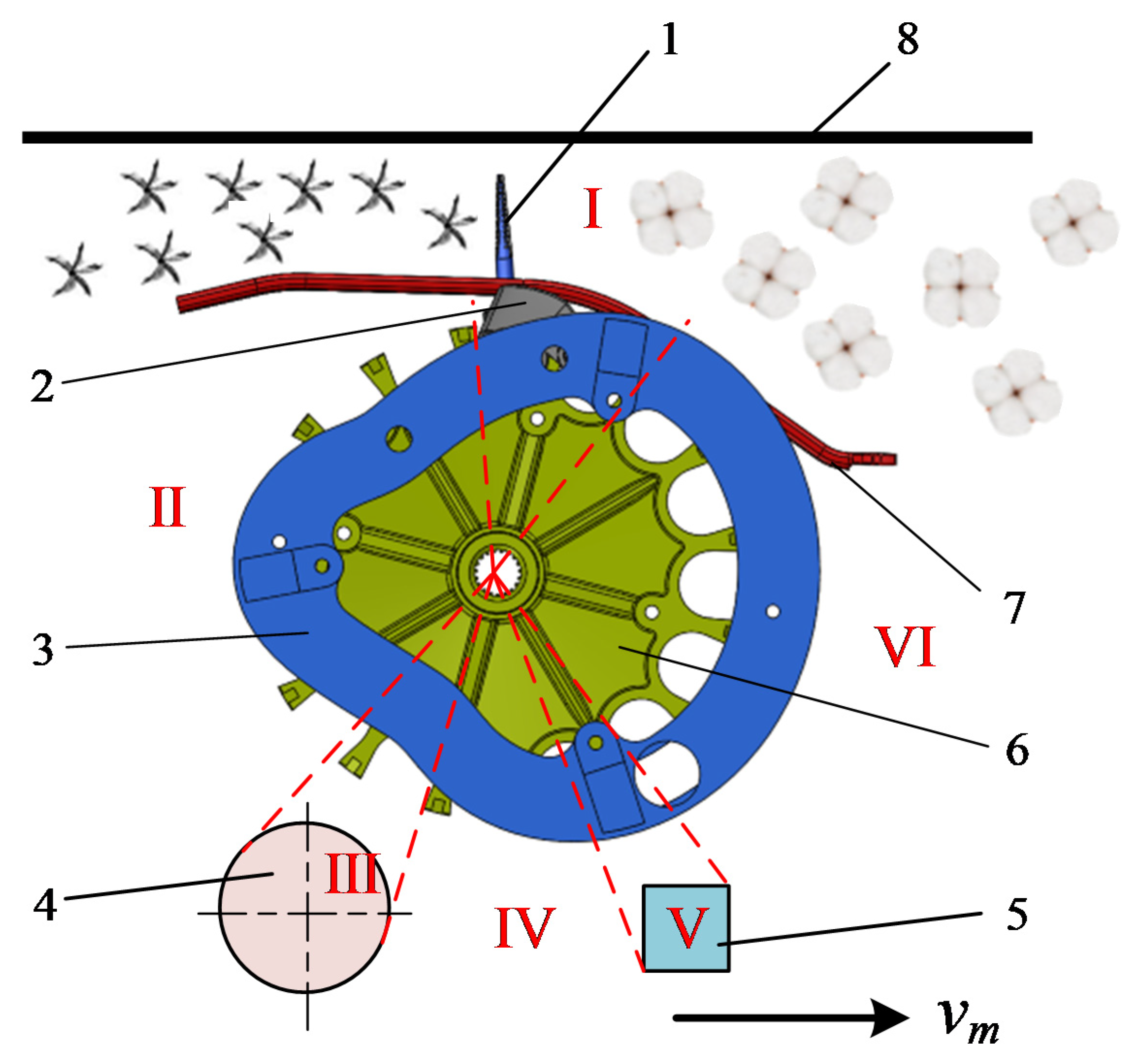
The working principle of the picking mechanism has been demonstrated in Figure 1. The picking head essentially consists of a spindle, crank, groove cam, doffer disk, moistening device, picking roller, grid plate, and pressure plate [24]. The cotton is compressed by the helper in the working process of the picking head and then enters the picking area, specified by I, which comprises the grating and pressure plate. At this time, the spindle, which is solidly connected with the crank, extends the grid plate with the rotation of the picking roller, and the guidance of the groove cam to contact the cotton plant squeezed in picking area I. The spindle with hooked teeth on the surface touches the open boll, and then the cotton fiber is entangled in the spindle due to the high rotational speed of the spindle. The spindle exits the picking area I with the rotation of the picking roller and then enters the stripping area III through the picking transition area II. This area comprises high-speed rotating stripping discs, which quickly strip the seed cotton from the spindle surface to complete the stripping process. The stripped seed cotton is then sent to the cotton box by the airflow conveying system through the cotton pipeline, and the stripped spindle enters the cleaning area V through the stripping transition area IV. The cleaning area consists of a moistening device, which is supplied with spindle cleaner through the pipe to clean the spindle to remove the residual cotton fiber, leaf pulp, and other inclusions on the surface of the spindle. Finally, the seed cotton enters the picking area I through the cleaning transition area VI to complete a picking cycle.
2.2. Mechanical Analysis of the Spindle Picking Process
The picking area I spindle along the forward direction of the cotton picker relative to the ground speed is approximately zero to prevent the spindle in the cotton-picking process from touching the cotton pole numerous times and damaging spindle hook teeth [24,25]. This condition is imposed because the picking area spindle driven by the picking drum’s backward rotation of the fractional speed is approximately equal to the cotton picker’s forward speed. The spindle along the forward direction of the cotton picker’s fractional speed can be neglected now, and only the spindle perpendicular to the cotton-picking process is taken into account.
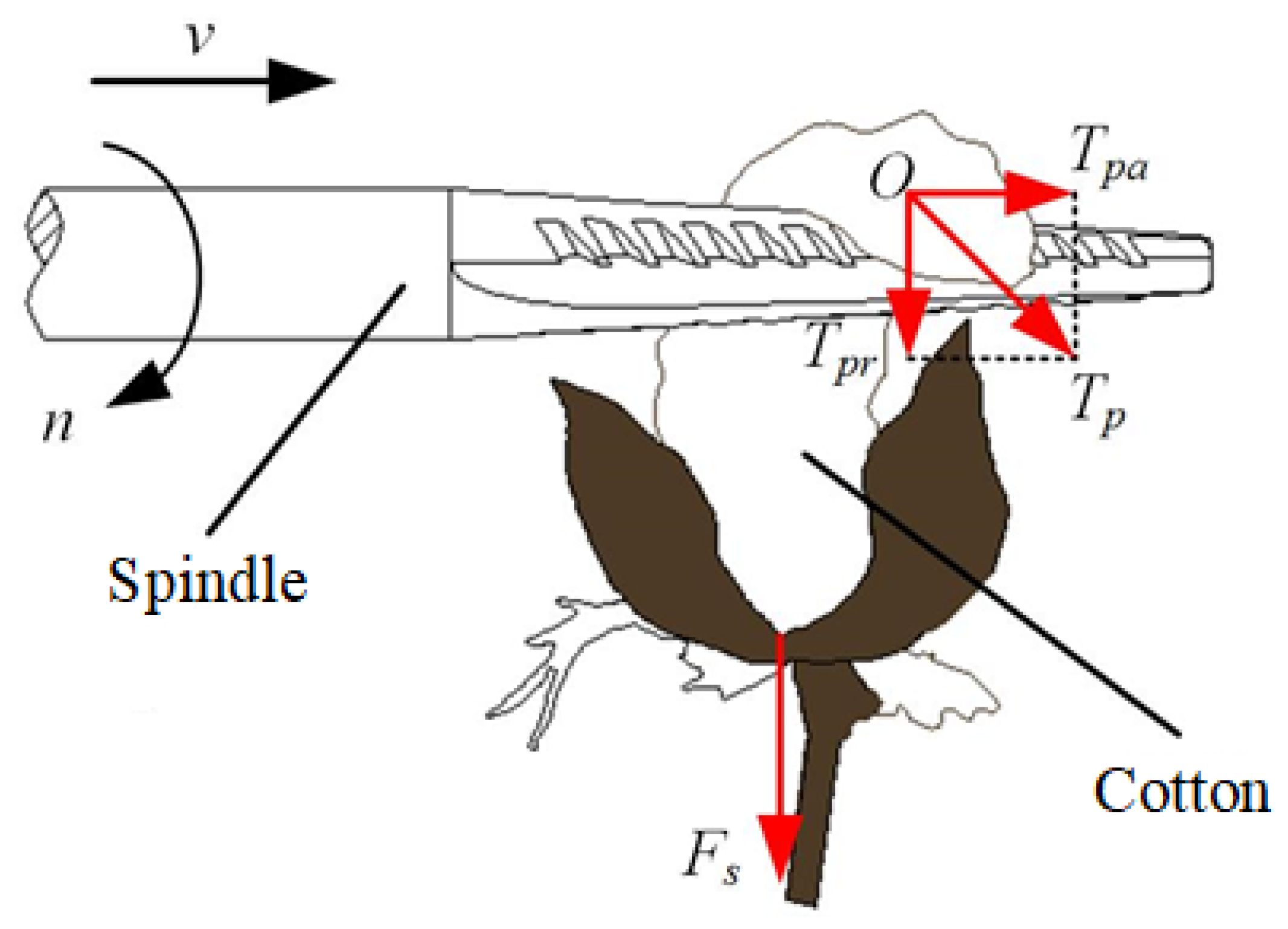
The spindle picking cotton process has been illustrated in Figure 2. As it is seen, the surface with hook teeth spindle with speed rotation n while moving to the cotton with feed speed v. The hook teeth will hanger the hanging cotton fiber during the course of contact, and the cotton spiral will wind in the spindle surface during the interaction of the feed speed v and the role of speed n.
A picking force Tp is formed due to the influence of friction on the cotton surface during spindle cotton picking. Taking a point O at the cotton surface as the analysis object, the picking force Tp can be decomposed to the axial picking force, Tpa, and the radial picking force, Tpr. Therefore, the relationship between these forces is presented by:
where Tp represents the picking force of cotton during spindle picking cotton, while Tpa and Tpr in order denote the axial and radial picking forces of the cotton during spindle picking cotton. The unit of all these forces is N.
Simultaneously, cotton can be subjected to the picking resistance, Fs, generated by the boll shell under the spindle due to the biological connection force between the cotton and boll shell. The following conditions must be satisfied to ensure the effective separation of the cotton from the boll shell:
where Fs represents the picking resistance of the boll shell to cotton during spindle picking.
The cotton wound on the surface of the spindle is also subjected to the external pressure Fp, centrifugal force Fc, and friction force Ff in the actual cotton picking. The supplementary explanations for Figure 2 are provided as follows:
2.2.1. External Pressure (Fp)
The cotton plants will be compressed in a certain space by the pressure plate after entering the picking area to facilitate efficient cotton picking. Subsequently, the cotton will be tightened by the external squeezing effect when the spindle touches and wraps around the cotton. The external pressure on the cotton during this phenomenon is expressed by:
where Fp represents the external pressure on the surface of the spindle winding cotton (N), p denotes the external pressure per unit area of cotton (Pa), and S denotes the cotton winding area (m2).
2.2.2. Centrifugal Force (Fc)
The actual high-speed spindle picking process, wherein the cotton performs rotational inertia on the impact of the picking force, must take the influence of centrifugal force into account. The centrifugal force is then evaluated as follows:
where Fc denotes the spindle surface winding cotton by the centrifugal force (N), m represents the unit length of the mass of cotton (kg), ωs is the spindle angular velocity (rad/s), and R denotes the spindle radius (m).
2.2.3. Frictional Force (Ff)
The cotton is spirally wound on the spindle surface under the action of the feeding speed v and the rotational speed n. The frictional force on the cotton fiber can be determined by considering the relevant data and the influence of the characteristics of the frictional object. Hence,
where Ff represents the friction force on the cotton fiber (N), μ is the friction constant (N/m2), f’ denotes the friction coefficient, and N represents the positive pressure on the spindle (N).
In the following, the radial picking force Tpr and the axial picking force Tpa are discussed separately to facilitate the upcoming discussion and examinations.
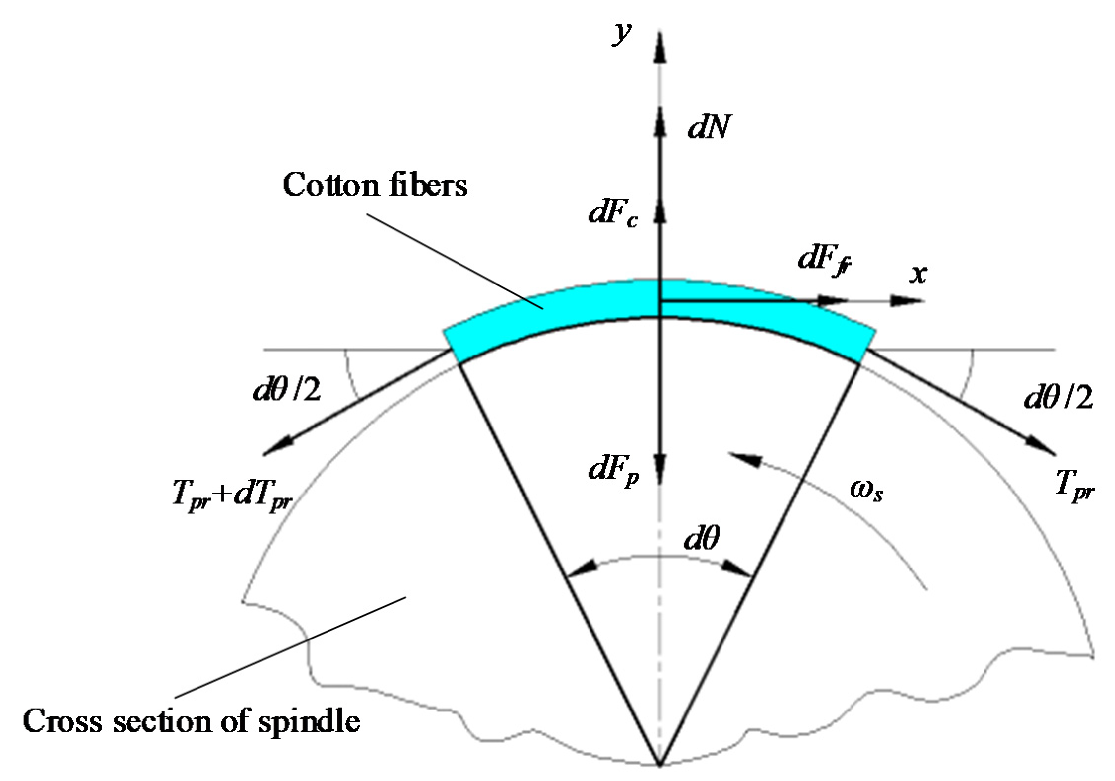
First, the front end of the spindle with teeth at a particular cross-section of a trace length of fiber strip is chosen as the study object to examine the radial picking force Tpr. Let us assume that the fiber strip is in its critical state from the rest condition to the accelerated motion. This problem can be solved and analyzed under the static equilibrium conditions of the joint cubic equation. Let the length of the fiber strip be dl and the radius of the spindle be R. The force analysis of the micro-length cotton fiber strip has been presented in Figure 3.
According to Figure 3, the requirement of satisfaction of the static equilibrium of the cotton sliver yields:
where denotes the tension on the right end of the trace length cotton fiber strip, is the tension on the left end of the trace length cotton fiber strip, is the frictional force on the radial trace length cotton fiber strip of the spindle, dθ is the wrap angle of the trace length cotton fiber strip corresponding to the spindle length of dl, is the external pressure on the trace length cotton fiber strip, is the positive pressure on the trace length cotton fiber strip of the spindle, represents the centrifugal force on the trace length cotton fiber strip, denotes the positive pressure of the spindle on the trace length cotton fiber strip, and represents the centrifugal force on the trace length cotton fiber strip.
The first differentiation of Equations (3)–(5) yields:
Now let dθ be a small angle value; therefore, , and . Additionally , which their expressions can be rationally neglected. As a result, Equation (6) can then be written as follows:
Combining Equations (7) and (8) yields the first-order linear differential equation as,
and by solving Equation (9) for Tpr accounting for both general and private solutions, we can get:
where represents a constant. The cotton fibers are hooked and fixed on the hook teeth in the actual picking process due to the presence of hook teeth on the spindle surface. The initial force of the hooking is set equal to , emphasizing that the magnitude of depends on the angular speed of the spindle and the physical properties of the cotton. The value of should then be determined by imposing the initial conditions . Hence,
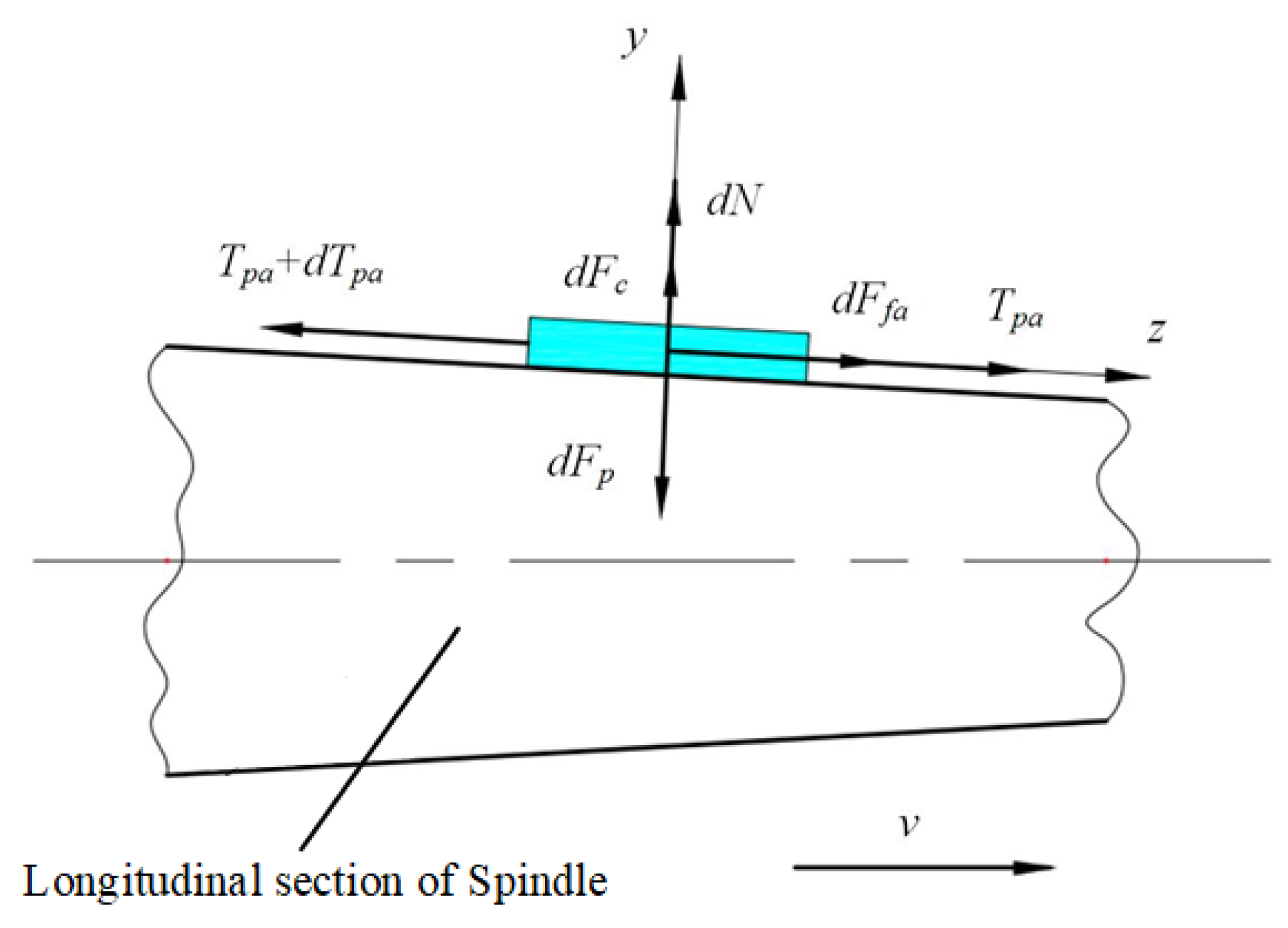
In the next step, we proceed to evaluate the axial picking force Tpa. To this end, a trace length of the fiber strip at a longitudinal section at the front end of the spindle with teeth is chosen as the object of understudy. The length of the cotton fiber strip is set as dl, and the spindle radius is R. The force analysis of the trace length of the cotton fiber strip can be conducted based on the free body diagram demonstrated in Figure 4.
Assume that the fiber strip is in a critical state from the rest condition to the accelerated motion. Therefore, the equilibrium equations can be expressed under the static equilibrium condition. Therefore,
where and in order represent the tension at the right and left ends of the trace length cotton fiber strip, and denotes the frictional force at the axial end of the trace length cotton fiber strip. The infinitesimal forces and in order denote the external pressure and positive pressure at the trace length cotton fiber strip, where the latter results from the picking spindle. Further, is the centrifugal force at the trace length, and is the centrifugal force on the cotton sliver fiber.
By taking the first differentiation of Equations (3)–(5),
in which the factor dl in Equation (14) can be stated by:
where is the required rotation time for the pick ingot at the angle with angular velocity .
By substituting Equation (14) to Equation (15), the following relation is obtained:
Equations (13) and (16) can jointly yield the following relation:
The integration of Equation (17) gives:
Obtained from Figure 2:
2.3. Analysis of the Structural Characteristics of the Spindle Hook Teeth
2.3.1. Analysis of the Overall Spindle Structure
The spindle of the cotton pickers essentially consists of the following four elements: bevel gear, picking spindle rod, picking spindle head, and hook teeth [26], as demonstrated in Figure 5. One end of the spindle is installed in the picking head of the spindle seat tube, and the bevel gear at the other end of the spindle engages with the bevel gear shaft in the spindle seat, which is exploited to drive the high-speed rotation of the spindle. The spindle rod is connected with the fixed seat, dust cover, back seat sleeve, and wear-resistant copper sleeve, which plays a fixed role in connection with the spindle seat tube.
The spindle head is also equipped with three rows of hook teeth whose minimum and maximum end diameters are denoted by dhmin and dhmax, respectively, and its length is represented by l. The cotton fiber is bent by the hook teeth when the spindle rotates at high speeds, and it comes into contact with the cotton, and then the cotton is entirely wound on the spindle surface by high-speed rotation, and the cotton is wholly separated from the bell shell [21,27].
The spindle head is the central working part of the spindle picking cotton in the actual cotton-picking process, and its shape has a considerable impact on the picking performance. This paper is aimed to examine various shapes of the spindle head cross-section, which are three shapes that are presented in Figure 6.
The surface of the spindle head is equipped with hook teeth, and the cotton fibers can fill the gaps of the hook teeth during cotton picking. Thus, the cross-section of the spindle head for winding cotton can be regarded as a circular cross-section. The dotted lines in Figure 6a–c show that the arc length of the outer circle corresponding to the edge is the angle of the sliver wrap when it is wound along the edge of the spindle head cross-section for a section of the cotton sliver. The friction force between the cotton and the spindle becomes significant when the angle of the sliver wrapped around the spindle surface is large. Under the premise of the same radius r of the external circle of the spindle head section, the corresponding bale angles of triangular, quadrilateral, and pentagon sections in order are 120°, 90°, and 72°. For a polygonal-based shape of the spindle head, the corresponding formula of the cut-off bale angle reads:
where represents the corresponding wrap angle when the cross-sectional shape of the spindle head is positive n-sided, °, and n denotes the number of sides of the cross-sectional shape of the spindle head.
The above formula shows that the largest value of is attained for the case of n = 3. In such a case, the maximum friction is produced between the sliver and the spindle. Therefore, the optimal picking effect is achieved when the spindle head cross-section is a positive triangle.
In addition to the cross-sectional shape of the spindle head, the outer circle diameter of the spindle head cross-section also has a considerable impact on its picking performance. The cotton will be squeezed by the pressure plate in the picking area of the spindle head, and then the cotton will arrange itself in a small space to form the spatial position distribution shown in Figure 7. As it is seen, the three consisting cottons are in contact with each other under the action of the externally applied pressure, and the hole-like space will be formed in the center of the three cottons due to the hard bell shell and its rigorous compression.
Figure 7 demonstrates that the radius of the bell shell, rc, is employed as the radius of the single cotton because the cotton is compressible, but the bell shell is not easily compressible. According to Figure 7, the centers of three cotton circles are specified by E, F, and Q, while their radius is denoted by rc. In the central position of the three cottons formed at the hole to make the inner circle, the center and radius of the circle associated with the hole are represented by O and rs. The tangential point of circles Q and E is denoted by M, and the tangent point of circles Q and O is signified by p. The lines OM, OP, QM, and QP are connected to obtain the right triangle OMQ, where the angle between the lines QM and QP is denoted by αs (αs = 30°), and the lengths of the segments OM, OP, QM, and QP length are represented by l1, rs, l2, and rc, respectively.
According to the geometric relationship presented in Figure 7, one can write:
Equation (21) can readily yield the following relation:
The actual picking process requires particular conditions to ensure the effective picking of the cotton. The first condition is that the spindle head must be inserted into the cotton aperture within the picking chamber, and the minimum end diameter, dhmin, of the spindle head must be less than the minimum diameter of the boll shell. This corresponds to the diameter of the cotton aperture at the inner connection circle O, dsmin. Thus, the following conditions should be satisfied:
Simultaneously, it should be ensured that the spindle can be fully in contact with the cotton and lessen the winding time during the spindle cotton-picking process. For this purpose, the spindle head in the cotton pore must meet the following conditions: the spindle head must have a conical structure, and the spindle’s head maximum end diameter dhmax must be larger than the maximum diameter of the bell shell associated with the cotton pore at the diameter of the inner connection circle O, dsmax. These conditions can be mathematically expressed as follows:
Through surveying the relevant literature, the maximum diameter of the machine-harvested cotton boll is 73.83 mm, and the minimum diameter of the cotton boll is 37.64 mm. Thus,
Equations (22)–(25) jointly yield the constraints on the maximum and minimum end diameters of the spindle head as follows:
The relevant literature [15] displays that in the presence of the spindle head of the picking chamber width of 10 mm, the spindle head length l must be less than the picking chamber width to ensure that the spindle in picking cotton does not touch the pressure plate. Consequently,
2.3.2. Analysis of the Spindle Hook Tooth Structure
The structural parameters of the hook tooth have a substantial impact on the hooking and winding of cotton in the process of picking cotton. Herein, the authors particularly focus on the impact of the characteristics of the hook tooth structure on spindle picking performance law. The spindle picking hook teeth, which are the key working parts of the spindle head, are mostly exploited for picking cotton hooking cotton fiber to prevent the high-speed rotation of the spindle surface picking of the cotton winding.
In general, the hook tooth of the spindle consists of “four sides and one tip” (front tooth surface, back tooth surface, rear tooth surface, side tooth surface, tooth tip), and the angle of the hook tooth plays a vital role in the picking performance of the spindle in the cotton-picking process, as demonstrated in Figure 8.
The cotton will be filled into the gap between the spindle hook teeth because of the externally applied pressure once the spindle is wound with cotton. This fact is indebted to the ductility of the cotton fiber. The front tooth surface is the guiding surface of the hook teeth when the cotton is squeezed and filled into the gap of the hook teeth. The side of the tooth is the main hooking surface of the hook teeth when hooking cotton fiber. The back of the tooth is the surface wherein the hook teeth wound the cotton fiber, which is crucial in winding cotton to enhance the friction of the spindle surface. The rear tooth surface is the guiding surface when the cotton on the hook teeth is squeezed and filled into the gap of the hook teeth and when the cotton is removed from the spindle in the process of shedding cotton. The tip of the tooth is the point where the front tooth surface, back tooth, and side tooth surface meet each other, which chiefly plays the role of hooking the cotton fiber.
The angle division and marking of the picking hook teeth are the indispensable portions of the design, manufacture, plating, and measurement processes of the picking hook teeth. The following three angles commonly play a crucial role in the picking process: the tooth groove angle, the before the tooth angle, and the tooth inclination angle, as demonstrated in Figure 8.
The angle βs is the angle between the side tooth surface and the tooth groove plane (see Figure 8a). For more clarification, let us take a point at the intersection of the side tooth surface and the tooth groove plane. The vertical lines and of the intersection of the side tooth surface and the tooth groove plane are respectively created over the point on the side tooth surface and the tooth groove plane. Therefore, the angle between the lines and represents the angle βs of the tooth groove.
Figure 8b shows the schematic diagram of the front tooth angle. The front tooth angle βf is the included angle between the tooth plane and the front tooth surface, that is, the included angle between line segments and is the front tooth angle βf.
Figure 8c is a schematic diagram of tooth inclination angle. Tooth inclination angle βt is the included angle between the side tooth surface and the front tooth surface, and the included angle between line segments and is the tooth inclination βt.
2.4. Spindle Picking Bench Test
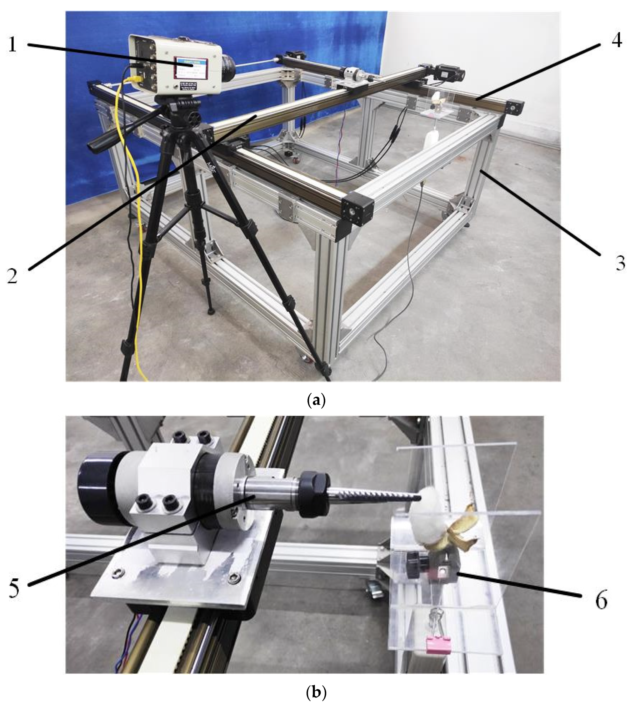
Combined with the actual spindle picking cotton process, a spindle picking performance test bench is designed to explore the influence of the angle of the spindle hook tooth on the picking performance. The test stand can simulate the spindle movement speed as well as the trajectory of cotton pickers in the field, completing the simulation of the single cotton picking. Meanwhile, the test stand is installed with a high-speed camera and a force sensor, which are capable of detecting the movement parameters and the picking performance of the spindle in real-time, providing a basis for the structural parameter optimization of the spindle in the later stage.
2.4.1. Test Materials and Equipment
The test sample was a machine-harvested cotton variety Huiyuan 720 taken from the second company of the second branch of Shihezi General Farm. The test cotton field was planted in wide and narrow rows of 66 cm + 10 cm machine-harvested cotton and sprayed with defoliant on 12 September 2020. The sample was then collected on 27 September 2020, when the defoliation rate of the cotton reached more than 85%, and the flocculation rate reached more than 90%. The cotton plants with suitable growth and no pests or diseases are selected on the day of defoliant spraying to avoid interference from unknown factors and ensure the validity of the test results. Cotton plants with four petals at the sixth fruiting branch near the main stem from the bottom up are also marked in advance as test samples [28,29], and 600 samples (with 100 spares) are taken at noon 15 days after defoliant spraying and stored in self-sealing bags after sampling. The samples are then stored in self-sealing bags.
The test equipment for conducting a dynamic picking test bench and the picking performance test on spindles includes a JM-B5003 electronic balance (Jiming, China, range 0–500 g, accuracy 0.001 g), a Fastec TS3 high-speed camera (voltage and current acquisition frequency synchronized to 50 Hz), an Edberg push-pull meter (range 0–10 N, accuracy 0.001 N), and a solid-tech general-purpose integrated motion controller.
The dynamic picking test bench design and picking performance test have been illustrated in Figure 9a,b. This bench mainly consists of a frame, an electrical control system, a guideway motion platform, a picking drive device, a cotton clamping force-measuring device, and a high-speed camera.
The guideway motion platform comprises one X-direction guide rail, two Y-direction guide rails, and a servo motor. The guideway adopts a synchronous belt module structure, and the servo motor drives the guideway slider to conduct reciprocating linear motion. The spindle drive device, which is installed on the X-direction guide rail, comprises a DC motor, clamps, and a spindle, which is used to drive its high-speed rotation. The cotton clamping force-measuring device, which is fixed at one end of the frame, comprises cotton clamps and an Eidelberg push-pull meter.
The actual cotton picker is limited to a small space in the picking area. Thus, the current study adds a limit plate on both sides of the cotton to simulate the actual cotton-picking process. The control system implements the software of Googoltech Oto Studio to write the program as well as drive the guide rail and spindle through the motion controller to complete the single.
2.4.2. Test Design and Evaluation Index
The key evaluation indexes of the picking performance of cotton pickers are operational efficiency and picking net rate [15]. As a key picking component of the cotton pickers, the picking performance of the spindle should reflect the picking efficiency and net rate. Instead of picking efficiency, the picking time (the time required for picking a single crop of cotton by the spindle) is considered as the evaluation index of the spindle picking performance to facilitate measurement and testing.
Through conducting pre-tests and examinations, the high-speed rotating spindle for fully mature cotton can effectively separate the cotton from the boll shell [16,30]. However, the seed cotton will be partially broken and thrown away by the centrifugal force when the seed cotton is separated from the boll shell. Therefore, the seed cotton throwing away rate is taken into account as the evaluation index of the picking performance, that is, the ratio of the mass of cotton thrown away by the spindle in the process of winding cotton to the total mass of the tested cotton.
The actual picking process in the field yields incompletely mature cotton, which is difficult to pick and requires high picking force. As a result, the picking force has been considered as the evaluation index in the present work.
From the perspective of spindle operation parameters, spindle and feeding speeds are employed as test factors, and the picking force Tp, picking time tp, and seed cotton throw-off rate Z are selected as evaluation indexes of the spindle picking performance in the current study according to pertinent studies and national standards [31]. Only one flap of the cotton sample is retained and clamped on the cotton clamping force-measuring device during the test. The height of the cotton clamping force-measuring device is adjusted such that the highest flap is at the same level as the end of the spindle. The speeds of the spindle and its feeding are also controlled by the upper computer program.
The picking force Tp is measured by the tension sensor on the cotton clamping force-measuring device, and the actual picking time tp of the cotton wrapped around the spindle is captured and collected by a high-speed camera. Finally, the electronic balance is used to measure the quality of the seed cotton under effective picking and that of the seed cotton that has been dumped to analyze the seed cotton-dumping rate Z.
The above evaluation index is calculated as follows:
where Tp1 represents the initial picking force on the cotton when the spindle does not touch the cotton, Tp2 denotes the maximum picking force on the cotton when the picking spindle picks the cotton, and the unit of all these forces is N. Furthermore,
where tp1 denotes the time when the picking spindle starts to touch the cotton, tp2 represents the time when the cotton is completely separated from the boll shell, and all their unit is s. The factor Z is defined by:
where M1 denotes the mass of cotton effectively picked by the spindle, M2 represents the mass of cotton thrown off by the spindle in the process of picking cotton, and their corresponding unit is kg.
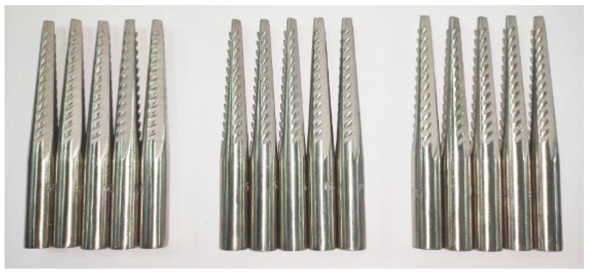
A single-factor test is conducted to clarify the influence law of the angle of the spindle hook tooth on the picking performance. In the present test, slot, tooth front, and tooth inclination angles are the test factors, seed cotton-dumping rate, picking time, and picking force are considered as the evaluation indexes. The widely used spindle parameters of cotton pickers are tooth groove angle 62°, before the tooth angle 89°, and tooth inclination angle 60°. Further, the variation ranges of the test factors are determined based on the relevant literature and previous test results [20,32]: tooth groove angle 54~70°, before the tooth angle 73~89°, tooth inclination angle 50~70°, and the specific picking hook tooth angle parameters are presented in Table 1. The diameter of the spindle is 12 mm. The spindle picking and spindle feed speeds are set equal to 4000 r/min and 1.8 m/s, respectively. The spindle employed in the test is constructed by using a metal 3D printer, as shown in Figure 10.
3. Results and Discussion
The single-factor test is employed, and 15 groups of tests are conducted. Each group of tests was repeated 20 times, and the average value is taken as the test results, as presented in Table 2.
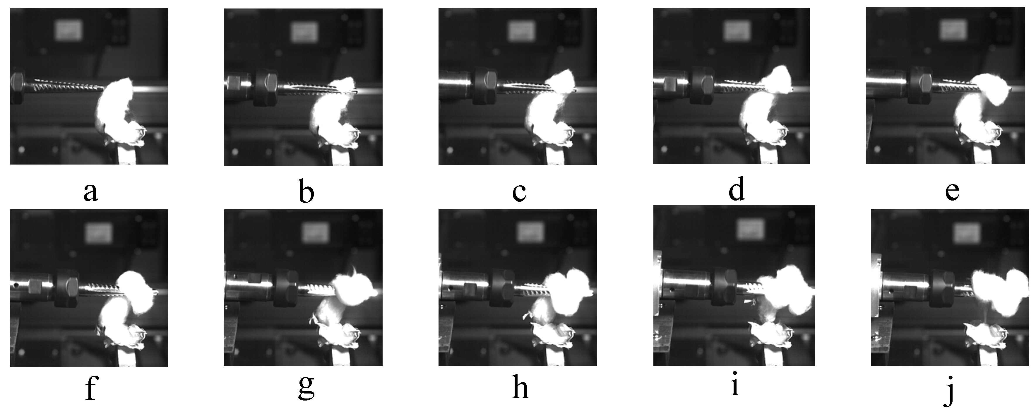
Figure 11 illustrates the high-speed camera process of the spindle picking cotton. The camera is set to 5100 fps. The spindle picking process can be successively divided into two stages: hooking and winding. In the hooking stage, a bundle of cotton fiber is hooked by the hook teeth of the spindle, which then pierces through the intricate intersection of the cotton fiber to form a fiber ring hanging on the hook teeth, completing the hooking process. The hooking force disappears as soon as the fiber ring is destroyed, and the size of the hooking force relies on the internal friction between the fiber ring and the mesh cotton fiber tissue. In the winding stage, the hook teeth of the spindle hook the cotton fiber bundle after the high-speed rotation of the spindle. The observed friction between the cotton fiber bundle and the spindle surface is due to the pressure between these two constituents. The spindle surface winds additional cotton fibers under the action of friction force. Finally, the friction force overcomes the tissue connection force between the cotton fiber and the cotton ball shell and completes the process of picking cotton.
A correlation analysis is conducted on the experimental data mentioned above to investigate the effect of different spindle hook angle parameters on the spindle picking performance, and the obtained results are provided in Table 3. Table 3 reveals that the tooth groove angle at the 0.01 level has a considerable influence on the ejection rate of seed cotton (p < 0.01), which is a negative correlation. The tooth inclination angle has a significant effect on the ejection rate of seed cotton (p < 0.01), presenting a negative correlation. The tooth inclination angle also has a remarkable effect on the picking time (p < 0.01), showing a positive correlation. In addition to the correlations mentioned above, the remaining results do not exhibit a significant correlation (p > 0.05).
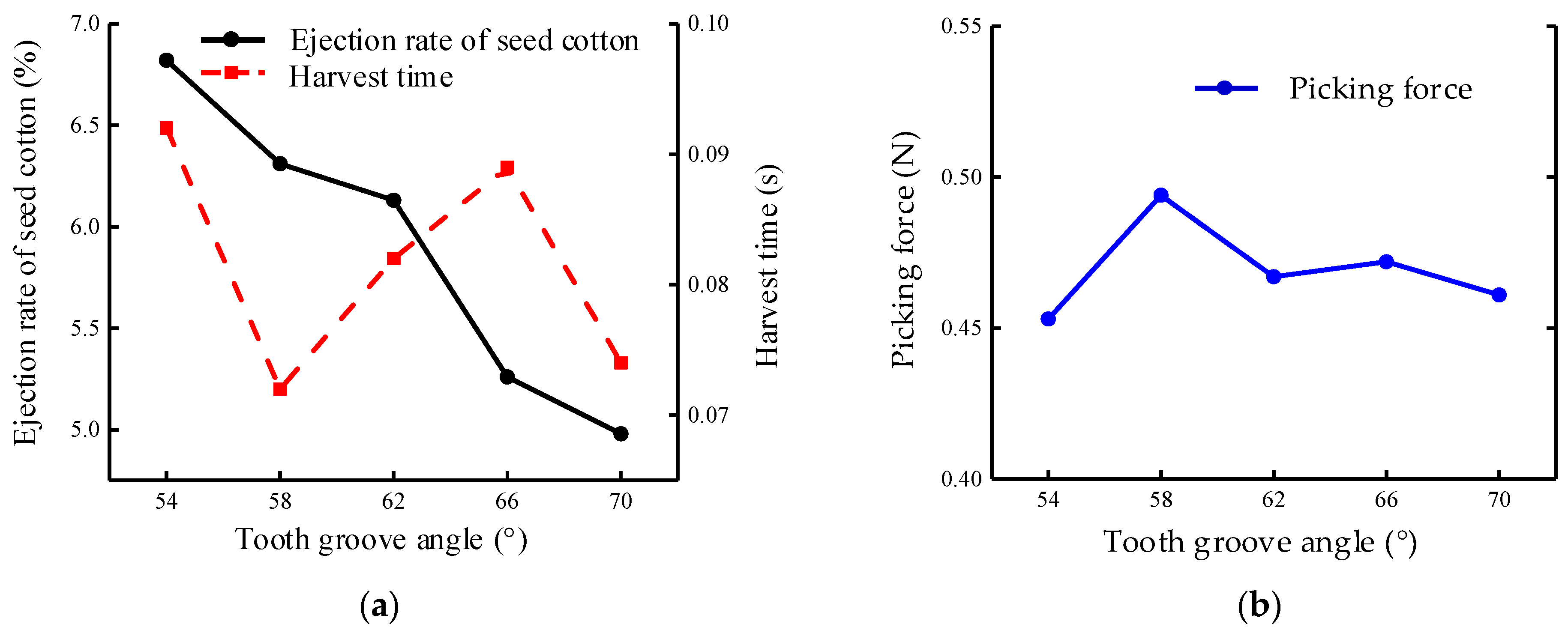
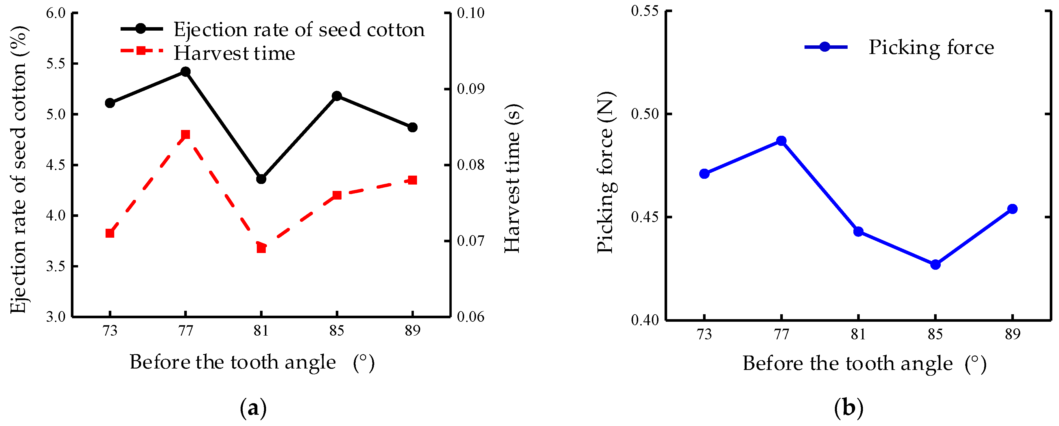
Figure 12, Figure 13 and Figure 14 demonstrate the influence of the tooth slot, tooth front, and tooth inclination angles on the picking performance of the spindle. Combined with the correlation analysis results given in Table 3, the tooth groove angle has a significant effect on the flinging rate of the seed cotton. The latter factor gradually lessens with the increase in the tooth groove angle.
However, the tooth groove angle has no considerable influence on the picking time and force, mostly due to the wrapping of the spindle around the cotton. Consequently, the cotton is squeezed into the tooth groove angle when the spindle is wrapped around the cotton: additional cotton is squeezed into the when the tooth groove angle is large, and the seed cotton is less likely to be thrown off. The front angle of the teeth also has a small effect on the ejection rate of seed cotton, picking time, and picking force.
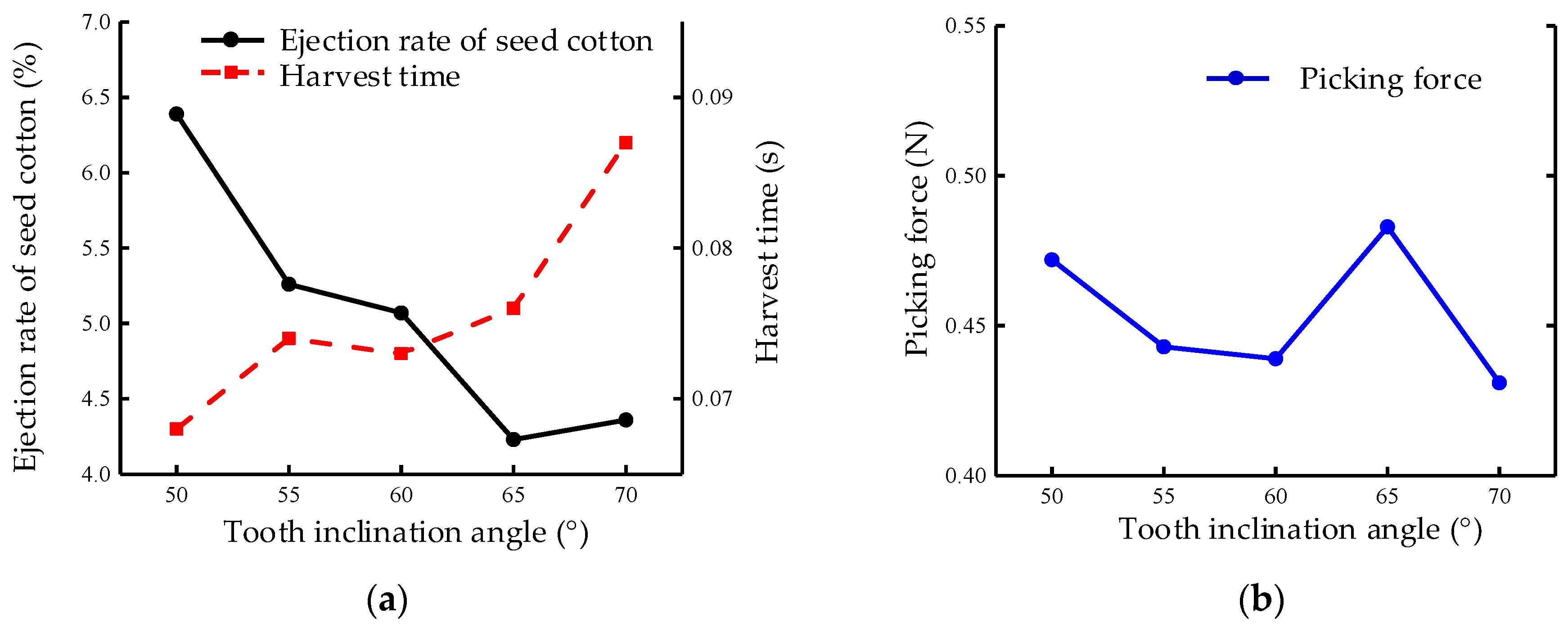
Generally, the front angle is aimed to facilitate the removal of cotton, and its impact on cotton picking is trivial. The tilt angle of the teeth has a major effect on the ejection rate of seed cotton and picking time. The ejection rate of seed cotton gradually reduces with the growth of the tilt angle, and the picking time gradually increases. However, the tilt angle has a substantial effect on the picking force. The tooth inclination angle has no significant influence on the picking force, the spindle picking trajectory is spiral, and the spindle rotation will simultaneously be found along with the axial feeding. The dumping rate of the seed cotton lessens when the tooth inclination angle is close to the spindle picking trajectory of the spiral angle. Simultaneously, the spindle along the spiral trajectory of the contact with the cotton indicates that a small tooth inclination angle facilitates easy piercing of the cotton fiber for hooking and winding.
Overall, the selection of the factors associated with the tooth groove angle should be as large as possible to reduce the ejection rate of seed cotton as well as picking time. In contrast, the selection of the tooth inclination angle factors cannot be excessively large or small, and the tooth inclination angle should be chosen in the range of 55~65°.
4. Conclusions and Future Work
In order to improve the picking performance of cotton pickers, a mechanical model suitable for the single-spindle picking process was established, and the influence of different hook tooth angle parameters on the picking performance of cotton pickers was revealed. The best section shape of the spindle head is the equilateral triangle section. Through the spindle picking performance test, it was concluded that the tooth groove angle and the tooth inclination angle were negatively correlated with the rejection rate of seed cotton (p < 0.01), and the tooth inclination angle was positively correlated with the picking time (p < 0.01). In order to reduce the ejection rate of seed cotton and reduce the picking time, a large tooth groove angle and tooth inclination angle should be selected in the range of 55°~65°. The optimum hook tooth angle parameters were determined as follows: tooth groove angle 70°, before the tooth angle 89°, and tooth inclination angle 65°. It has practical significance in optimizing the structure of spindle hook tooth and improving picking performance. In future work, we plan to apply the experimental results to the cotton picker to improve the picking performance of the spindle and the operating efficiency of the cotton picker.
Author Contributions
Conceptualization, L.W. and C.Y.; Data curation, L.W. and H.Z.; Formal analysis, L.W. and H.L.; Funding acquisition, H.Z. and L.W.; Investigation, L.W., C.Y. and L.Z.; Methodology, L.W. and L.Z.; Project administration, L.W. and H.Z.; Resources, L.W. and C.Y.; Software, L.W. and L.Z.; Supervision, H.Z.; Validation, L.W., L.Z., C.Y., H.Z. and H.L.; Visualization, L.W. and C.Y.; Writing—original draft, L.W. and L.Z.; Writing—review and editing, L.W. and C.Y. All authors have read and agreed to the published version of the manuscript.
Funding
This work was supported by the National Natural Science Foundation of China (grant no. 51605314) and the Corps Key Field Innovative Team Building Project (grant number: 2019CB006).
Institutional Review Board Statement
Not applicable.
Informed Consent Statement
Not applicable.
Data Availability Statement
The data presented in this study are available on-demand from the first author at ([email protected]).
Acknowledgments
The authors would like to thank their schools and colleges, as well as the funding of the project. All support and assistance are sincerely appreciated. Additionally, we sincerely appreciate the work of the editor and the reviewers of the present paper.
Conflicts of Interest
The authors declare no conflict of interest.
References
- Shen, S.H.; Wang, L.Q. Research on China’s Cotton Industry Security under Open Conditions. China Cotton 2022, 49, 1–6. [Google Scholar]
- Lu, X.R.; Jia, X.Y.; Niu, J.H. The Present Situation and Prospects of Cotton Industry Development in China. Sci. Agric. Sin. 2018, 51, 26–36. [Google Scholar]
- Niu, G.L.; Li, B.; Liu, Y.; Li, Y.X.; Wang, T.; Wang, S.G. Development and Research Status of Cotton Picker in China. J. Chin. Agric. Mech. 2020, 41, 212–218. [Google Scholar]
- Wu, C.Y.; Feng, J.; Chen, C.Q.; Wang, J.H.; Liu, C.; Lin, Y.; Kang, J.M. Analysis of the Status Quo and Mechanization Development of Cotton Producing Industry in China. J. Chin. Agric. Mech. 2021, 42, 215–221. [Google Scholar]
- Meng, F.; Chen, N.; Chen, Z. Hard Chromium Coating Effects on Tribological Performances for Nonlubricated and Lubricated Spindle of Cotton Picker. Proc. Inst. Mech. Eng. Part L J. Mater. Des. Appl. 2016, 230, 446–453. [Google Scholar] [CrossRef]
- Zhang, Y.Q.; Cai, Z.P.; Tian, Y.; Meng, Y. Improvement of Mechanical Properties and Wear Resistance of Cotton Pickers Spindle by Electromagnetic Treatment. Trans. Chin. Soc. Agric. Eng. 2018, 34, 31–37. [Google Scholar]
- Zhang, Y.; Tian, Y.; Meng, Y. Wear Behavior of Spindles of Cotton Picker in Field Work. J. Tribol. Trans. Asme 2021, 143, 021703. [Google Scholar] [CrossRef]
- Li, W.C.; Qiao, Y.Y.; Deng, Y.M.; Liu, X.M.; Zhang, H.W. Valuation and Analysis of Hook Tooth Wear for Cotton Picker Spindle. J. Chin. Agric. Mech. 2018, 39, 11–14. [Google Scholar]
- Amanov, A.; Sembiring, J.P.B.A.; Amanov, T. Experimental Investigation on Friction and Wear Behavior of the Vertical Spindle and V-Belt of a Cotton Picker. Materials 2019, 12, 773. [Google Scholar] [CrossRef] [Green Version]
- Gu, Y.; Zhang, H.; Fu, X.; Wang, L.; Shen, Z.; Wang, J.; Song, Z.; Zhang, L. Experimental Wear Behavior Analysis of Coated Spindle Hook Teeth under Real Harvesting Work Conditions. Materials 2021, 14, 2487. [Google Scholar] [CrossRef]
- Omonov, N.N.; Abdazimov, A.D.; Atadjanova, M.M.; Shodiyev, J.G. Investigation of Spindle Activity of Horizontal Spindle Cotton Harvesting Machine. IOP Conf. Ser. Earth Environ. Sci. 2021, 868, 012073. [Google Scholar] [CrossRef]
- Ravutov, S.T.; Olimjonov, R. Features of Picking Cotton from the Spindles of a Vertical-Spindle Cotton Picker with Their Variable Kinematic Modes. IOP Conf. Ser. Earth Environ. Sci. 2021, 868, 012071. [Google Scholar] [CrossRef]
- Zhang, Y.Q.; Ma, S.H.; Ding, W.C. Dynamic Analysis on Picking Process of Cotton Picker Spindle. Trans. Chin. Soc. Agric. Eng. 2012, 28, 54–58. [Google Scholar]
- Chen, T.G.; Zhang, H.W.; Wang, L.; Wang, Y.G.; Zhang, L.C.; Liu, X.M. Research and Experiment on Movement Characteristics of Picking Mechanism of Horizontal Picking Cotton Picker. Trans. Chin. Soc. Agric. Eng. 2020, 41, 19–25. [Google Scholar]
- Chen, T.G.; Zhang, H.W.; Wang, L.; Zhang, L.C.; Wang, J.; Li, J.X.; Gu, Y.Q. Optimization and Experiments of Picking Head Transmission System of Horizontal Spindle Type Cotton Picker. Trans. Chin. Soc. Agric. Eng. 2020, 36, 18–26. [Google Scholar]
- Li, T.; Hao, F.P.; Han, Z.D.; Fang, X.F.; Hao, Z.H.; Liu, Y.Q. Design and Test of Horizontal Spindle Picking Head with High Efficiency. J. Chin. Agric. Mech. 2018, 49, 233–238. [Google Scholar]
- Zhang, L.C.; Zhang, H.W.; Wang, L.; Fu, X.Q.; Chen, T.G.; Wang, J.; Gu, Y.Q. Influence of Different Boll Shell Physical Parameters on Mechanical Properties of Machine-Harvested Cottons. Trans. Chin. Soc. Agric. Eng. 2020, 36, 30–37. [Google Scholar]
- Baker, K.D.; Hughs, E.; Foulk, J. Cotton Quality as Affected by Changes in Spindle Speed. Appl. Eng. Agric. 2010, 26, 363–369. [Google Scholar] [CrossRef]
- Baker, K.D.; Hughs, E.; Foulk, J. Spindle Speed Optimization for Cotton Pickers. Appl. Eng. Agric. 2015, 31, 217–225. [Google Scholar]
- Baker, K.D.; Delhom, C.D.; Hughs, S.E. Spindle Diameter Effects for Cotton Pickers. Appl. Eng. Agric. 2017, 33, 321–327. [Google Scholar] [CrossRef]
- Zhou, Y.L.; Sun, W.L.; Luo, X.L. New Structure and Parametric Optimization of Horizontal Spindle-type Cotton Picker’s Spindle. Mech. Eng. Auto. 2012, 1, 10–12. [Google Scholar]
- Wu, B. The Analysis of Cotton-Picker Level Spindle’s Material and Heat Treatment Process; Shihezi University: Shihezi, China, 2013. [Google Scholar]
- Sun, Z.; Sun, W.L.; Yu, S.L. Combination and Variation Method-based Cotton Picker Machine Spindle Shape Variation Studies. J. Agric. Mech. Rese. 2019, 41, 45–50. [Google Scholar]
- Liu, X.M.; Zhang, H.W.; Wang, L.; Chen, T.G.; Zhang, L.C.; Wang, Y.Z.; Li, G.G.; Zhang, Y. Study on Winding Model of Spindle Picking Cotton for Horizontal Cotton Picker. Jour. Agric. Mech. Rese. 2020, 42, 13–19. [Google Scholar]
- Rizaev, A.; Matchanov, R.; Yuldashev, A.T.; Kuldashev, D.A.; Djuraeva, N.B.; Karimov, N.; Ashurov, N. Cotton Harvesters for One-Time Cotton-Picking. IOP Conf. Ser. Mater. Sci. Eng. 2021, 1030, 012173. [Google Scholar] [CrossRef]
- Bi, X.S. Research on the Working Mechanism of the Horizontal Spindle Picking Head of the Cotton Picker; Shihezi University: Shihezi, China, 2007. [Google Scholar]
- Yu, S.L.; Zhu, Q.L.; Wang, X.C.; Liu, H.C.; Liu, S.C. Research on Multi Position Forming Method of Picking Spindle Hook Teeth Group of Cotton Picker Based on Machining Center. Mach. Build. Auto. 2021, 50, 33–48. [Google Scholar]
- Wang, R.D.; Yin, J.Z. Crop Cultivation; Higher Education Press: Beijing, China, 2005. [Google Scholar]
- Araujo, T.A.; Araujo, L.H.A.; Silva, N.R.; Luz, C.E.A.; da Silva, E.M.; Moreira, M.D.; Suinaga, F.A.; Picanco, M.C.; Bastos, C.S. Standardized Sampling Plan for Aphis Gossypii Based on the Cotton Cultivar, Plant Phenology and Crop Size. J. Appl. Entom. 2019, 143, 893–901. [Google Scholar] [CrossRef]
- Yan, J.G. Experimental Research on Picking Performance of Cotton Picker Spindle; Shihezi University: Shihezi, China, 2013. [Google Scholar]
- Ministry of Agriculture of the People’s Republic of China. Quality of Cotton Picker Operations: NY/T1133-2006; China Standard Publishing House: Beijing, China, 2006.
- Wei, L.Q.; Wei, M.; Chen, B.; Ge, Y. The Finite Element Analysis and Structure Optimization of Cotton Picker Horizontal Spindles. J. Agric. Mech. Res. 2014, 36, 20–23. [Google Scholar]
Figure 1.
Schematic diagram of the working principle of the picking head (note: the consisting parts are as follows, 1. spindle, 2. crank, 3. groove cam, 4. doffer disk, 5. moistening device, 6. picking roller, 7. grid plate, 8. pressure plate; the factor vm represents the forward speed of the cotton picker, and n denotes the speed of the picking drum).

Figure 2.
Schematic representation of the spindle picking process.

Figure 3.
Free body diagram of the cotton sliver in the cross-section of the spindle.

Figure 4.
Free body diagram of the cotton sliver in the longitudinal section of the spindle.

Figure 5.
The overall structure sketch of the spindle. 1. Bevel gear, 2. spindle rod, 3. spindle head, 4. hook tooth.
Figure 5.
The overall structure sketch of the spindle. 1. Bevel gear, 2. spindle rod, 3. spindle head, 4. hook tooth.

Figure 6.
Schematic representation of the spindle head section with various shapes: (a) equilateral triangular section, (b) normal quadrilateral section, (c) regular pentagon section; (note: in the presented subfigures, γ3, γ4, and γ5 are, respectively, the wrapping angles of the equilateral triangle section, the equilateral quadrilateral section, and the equilateral pentagon section, °; r is the circumcircle radius of the spindle head section).

Figure 7.
Spatial distribution diagram of the spindle and the cotton during cotton picking.

Figure 8.
Schematic representation of the tooth angle division of the spindle hook.

Figure 9.
Test bench for dynamic picking performance of the spindle: (a) integrated test graph, (b) partial schematic (note: the consisting parts of the test apparatus are: 1. high-speed camera, 2. X-direction guide rail, 3. frame, 4. Y-direction guide rail, 5. picking ingot driving device, 6. cotton clamping force-measuring device).

Figure 10.
Samples of used spindles in the test.

Figure 11.
High-speed camera process of the spindle picking a flap of cotton: (a) picking spindle and cotton just contact, (b–c) hook picking stage, (d–h) winding stage, (i) cotton fiber and cotton boll shell will be separated, (j) the completion of picking.
Figure 11.
High-speed camera process of the spindle picking a flap of cotton: (a) picking spindle and cotton just contact, (b–c) hook picking stage, (d–h) winding stage, (i) cotton fiber and cotton boll shell will be separated, (j) the completion of picking.

Figure 12.
Effect of the tooth angle on the picking performance of the spindle: (a) tooth groove angle (ejection rate of seed cotton and harvest time), (b) tooth groove angle (picking force).
Figure 12.
Effect of the tooth angle on the picking performance of the spindle: (a) tooth groove angle (ejection rate of seed cotton and harvest time), (b) tooth groove angle (picking force).

Figure 13.
Effect of the tooth anterior angle on the picking performance of the spindle: (a) before the tooth angle (ejection rate of seed cotton and harvest time), (b) before the tooth angle (picking force).
Figure 13.
Effect of the tooth anterior angle on the picking performance of the spindle: (a) before the tooth angle (ejection rate of seed cotton and harvest time), (b) before the tooth angle (picking force).

Figure 14.
Effect of the tooth inclination angle on the picking performance of the spindle: (a) tooth inclination angle (ejection rate of seed cotton and harvest time), (b) tooth inclination angle (picking force).
Figure 14.
Effect of the tooth inclination angle on the picking performance of the spindle: (a) tooth inclination angle (ejection rate of seed cotton and harvest time), (b) tooth inclination angle (picking force).


Table 1.
The tooth angle factors of the spindle hook.
| Tooth Groove Angle (°) | Before the Tooth Angle (°) | Tooth Inclination Angle (°) |
|---|---|---|
| 54 | 73 | 50 |
| 58 | 77 | 55 |
| 62 | 81 | 60 |
| 66 | 85 | 65 |
| 70 | 89 | 70 |
Table 2.
The performance results of the spindle with various angle parameters of the hook teeth.
| The Angle Parameters of the Spindle Hook Teeth | The Angle (°) | Ejection Rate of the Seed Cotton (%) | Harvest Time (s) | Picking Force (N) |
|---|---|---|---|---|
| Tooth groove angle | 54 | 6.82 | 0.092 | 0.453 |
| 58 | 6.31 | 0.072 | 0.494 | |
| 62 | 6.13 | 0.082 | 0.467 | |
| 66 | 5.26 | 0.089 | 0.472 | |
| 70 | 4.98 | 0.074 | 0.561 | |
| Before the tooth angle | 73 | 5.11 | 0.071 | 0.471 |
| 77 | 5.42 | 0.084 | 0.487 | |
| 81 | 4.36 | 0.069 | 0.443 | |
| 85 | 5.18 | 0.076 | 0.427 | |
| 89 | 4.87 | 0.078 | 0.454 | |
| Tooth inclination angle | 50 | 6.39 | 0.068 | 0.472 |
| 55 | 5.26 | 0.074 | 0.443 | |
| 60 | 5.07 | 0.073 | 0.439 | |
| 65 | 4.23 | 0.076 | 0.483 | |
| 70 | 4.36 | 0.087 | 0.431 |
Table 3.
Correlation test results of various hook angle parameters.
| The Angle Parameters of the Spindle Hook Teeth | Ejection Rate of Seed Cotton (%) | Harvest Time (s) | Picking Force (N) |
|---|---|---|---|
| Tooth groove angle | −0.981 ** | −0.340 | 0.719 |
| Before the tooth angle | −0.283 | 0.160 | 0.634 |
| Tooth inclination angle | −0.931 ** | 0.901 ** | −0.294 |
Note: **. Indicate significant difference at 0.01 levels.
Publisher’s Note: MDPI stays neutral with regard to jurisdictional claims in published maps and institutional affiliations. |
© 2022 by the authors. Licensee MDPI, Basel, Switzerland. This article is an open access article distributed under the terms and conditions of the Creative Commons Attribution (CC BY) license (https://creativecommons.org/licenses/by/4.0/).
Share and Cite
MDPI and ACS Style
Wang, L.; Yin, C.; Zhang, L.; Zhang, H.; Li, H. Analysis and Experiment on the Impact of Various Hook Angle Factors on Spindle Picking Performance. Agriculture 2022, 12, 768. https://doi.org/10.3390/agriculture12060768
AMA Style
Wang L, Yin C, Zhang L, Zhang H, Li H. Analysis and Experiment on the Impact of Various Hook Angle Factors on Spindle Picking Performance. Agriculture. 2022; 12(6):768. https://doi.org/10.3390/agriculture12060768
Chicago/Turabian StyleWang, Lei, Chenghai Yin, Longchang Zhang, Hongwen Zhang, and Haiyang Li. 2022. "Analysis and Experiment on the Impact of Various Hook Angle Factors on Spindle Picking Performance" Agriculture 12, no. 6: 768. https://doi.org/10.3390/agriculture12060768
Note that from the first issue of 2016, this journal uses article numbers instead of page numbers. See further details here.