
Investigations on the Potentials of Novel Technologies for Aircraft Fuel Burn Reduction through Aerostructural Optimisation

1
Institute of Aircraft Design and Lightweight Structures, Technische Universität Braunschweig, 38106 Braunschweig, Germany
2
Computational Engineering and Design Group, Department of Aeronautics and Astronautics, University of Southampton, Southampton SO16 7QF, UK
*
Author to whom correspondence should be addressed.
Aerospace 2022, 9(12), 744; https://doi.org/10.3390/aerospace9120744
Submission received: 28 October 2022
/
Revised: 16 November 2022
/
Accepted: 21 November 2022
/
Published: 23 November 2022
(This article belongs to the Section Aeronautics)
Abstract
:A physics-based optimisation framework is developed to investigate the potential advantages of novel technologies on the energy efficiency of a midrange passenger aircraft. In particular, the coupled-adjoint aerostructural analysis and optimisation tool FEMWET is modified to study the effects of active flow control at different load cases for conventional and unconventional wing configurations. This multidisciplinary design optimisation (MDO) framework presents the opportunity to optimise the wing considering static aeroelastic effect and, by its gradient-based method, save substantial computational time compared to high-fidelity tools, keeping a satisfying level of accuracy. Two different configurations are analysed: a forward- and backward-swept wing aircraft, developed inside the Cluster of Excellence SE2A (Sustainable and Energy-Efficient Aviation). The forward-swept configuration is sensitive to the aeroelastic stability effect, and the backward configuration is influenced by the aileron constraint. They may lead to a weight increment. Sensitivity studies show the possible role of key parameters on the optimisation results. The highest fuel weight reduction achievable for the two configurations is 5.6% for the forward-swept wing and 9.8% for the backward configuration. Finally, both optimised wings show higher flexibility.
1. Introduction
During the last century, globalization, various financial crises, climate change, and an increasing scarcity of resources have come to represent new challenges for Europe. Governments recognize the necessity of innovation and of a common strategy to keep Europe competitive for the long term. Flightpath 2050 [1] sets promising but challenging goals for new generations of aircraft, such as reducing CO and NO emissions by 75% and 90%, respectively, as well as a 65% noise reduction. Researchers from all over the world are working on reducing emissions and noise, as well as life-cycle concepts for structures and potential improvements in air traffic management. In particular, technologies like active flow control, load alleviation, boundary-layer ingestion, and advanced structures are studied for more sustainable aviation.
Load alleviation is performed with different methodologies via passive or active approaches to have more favorable wing load distribution (to reduce bending moments) and hence structural weight reduction. A lower maximum bending moment allows one to design wings for a lower limit load factor. The techniques implemented for passive load alleviation are nonlinear stiffness material design [2], viscoelastic damping design [3], new structural concepts [4,5], and, finally, local morphing structures [2]. Rossow et al. [6] investigated the feasibility of an aircraft, ideally designed to sustain 1g as maximum load (typical for a cruise mission) and the use of load alleviation to take care of all the loads deviating from this 1g case. Wing mass can be reduced by 60%. Wing flow control represents a methodology for active load alleviation because it is able to reach a more favorable load distribution and, as a consequence, to reduce wing-bending moment. Liu et al. [7] designed robust control laws for a large, flexible wing with uncertainty in the Mach number and dynamic pressure in order to investigate the active load alleviation by means of a controller. Ying et al. [8] investigated an active control technique by using piezoelectric actuators to alleviate gust-response loads of a large-aspect-ratio flexible wing. Finally, a dedicated gust load-alleviation system can be based on fluidic or micromechanical flow actuators distributed over the wingspan, able to reach an efficient lift redistribution leading to substantial reductions in wing weight [9].
Active flow control as a means of wing laminarisation, and, consequently, aircraft drag reduction, can be assessed by different techniques, for example boundary layer suction (BLS). Experimental activities regarding laminar flow control (LFC) applied on aircraft date back to the 1930s [10]. The so-called natural laminar flow (NLF) airfoils are airfoils implemented to passively reach laminar flow, generally over the forward aeroplane lifting surfaces. Considering a limited leading-edge sweep angle, generally lower than 18 degrees, local pressure initially decreases over the surface for a leading-trailing edge direction. In order to keep the laminar flow in the rearward region and avoid early transition, triggered by instabilities due to the adverse pressure gradient, active flow control techniques are implemented. For these reasons, in the last few decades, scientific research was mainly addressed by a combination of the two approaches described, defined as hybrid laminar flow control (HLFC) [11]. More recently, Boeing has mounted an HLFC system for the horizontal and vertical tail of its B787-9, and benefits are reported as significant [12]. HLFC is characterised by natural laminar flow as a limited portion of the airfoil, whereas the remaining desired laminarisation is extended through BLS. Beck et al. [13] studied a midrange forward-swept wing configuration with an 80% laminar flow wing and a 70% laminarised fuselage, with a potential for fuel burn reduction up to 47%. Sudhi et al. performed a 2D optimisation for airfoil shape design to minimise drag and power absorbed by BLS for a subsonic unswept wing [14]. The HLFC optimised airfoil, with onset suction fixed at 50%, gives a parasite drag reduction of 31%. Design optimziation of a fully electric regional aeroplane with HLFC is studied in [15], showing a reduction of profile drag of more than 38% achieved by using BLS. In addition, HLFC is also applied to a transonic swept wing for airfoil design; in detail, the optimised HLFC section may reduce 43% of profile drag with respect to the airfoil optimised for NLF [16].
In the literature, different frameworks are designed for wing aerostructural optimisation. Aerostructural analysis cannot be properly treated with low-fidelity tools; in fact, the wing weight estimation will not take into account the flexibility of the wing itself due to the aerodynamic loads. Generally, high-fidelity tools are used, as in Liem et al. [17], for structural wing analysis through the finite element analysis tool, whereas the aerodynamic part is studied for an inviscid and incompressible flow, the data for which are used to build a surrogate model. The computational time for the high-fidelity level may be not affordable and requires proper parallelisation. High-fidelity analysis becomes a relevant approach when the basic parameters are available and aircraft components need to be improved for specific effects. However, this solution implies high computational power and cost (for a complete overview of the fidelity layers, see [18]).
For these reasons, the use of medium-fidelity but physics-based analysis methods represent a promising approach and tradeoff between a low-fidelity design with low computational power and the most advanced analysis, the cost of which may not be affordable. This research aims to present a medium-fidelity but physics-based analysis and optimisation framework for wing aerostructural optimisation, developed and applied to investigate the advantages of the mentioned novel technologies on aircraft energy efficiency. The use of a gradient-based optimisation allows the use of a large number of design variables with good accuracy and low computational time; to facilitate a gradient computation, the coupled adjoint sensitivity analysis method [19] is implemented. The main focus is given to the active flow control, in particular the different level of wing laminarisation through a drag penalty model, and the use of different load cases to simulate future scenarios in which aircraft would be allowed to fly at different maximum load factors (potentially lower than the current 2.5 g [20]) thanks to the load-alleviation technology that will sustain the possible higher loads, similar to the idea researched in [6]. Considering the transonic regime of the aircraft, the possibility of aileron reversal conditions and static divergence needs to be considered. Flutter divergence is not taken into account because of the medium-fidelity framework, and the condition needs to be verified for a more advanced fidelity level. Two different aircraft are analyzed, a backward- and forward-swept midrange aircraft developed in the Cluster of Excellence SE2A (Sustainable and Energy-Efficient Aviation) [2]. The SE2A is an interdisciplinary research center developed in Germany to pursue the abovementioned objectives by investigating different technologies.
Finally, the current research is focused on the following:
- the development of a midfidelity adjoint, gradient-based, aerostructural optimisation framework able to take into account novel technologies and nonconventional aircraft configuration for sustainable application, like fuel weight minimisation;
- the understanding of the limitations present in both aircraft configurations and the role of the aeroelastic constraints;
- sensitivity studies for the optimisation key parameters; and
- evaluation of how fuel weight minimisation may be influenced by the technologies and the optimised variables.
The present work is divided into several sections. Section 2 focuses on the SE2A midrange aircraft, and Section 3 clarifies the aerostructural analysis. Section 4 explains the multidisciplinary design optimisation, and Section 5 presents all the results of the study. In the last section, conclusions are defined.
2. SE2A Midrange Aircraft
This study is applied to the midrange aircraft design of the Research Cluster of Excellence Sustainable and Energy Efficient Aviation [21]. This aircraft is designed with the top-level requirements selected similarly to the reference A320, summarised in Table 1.
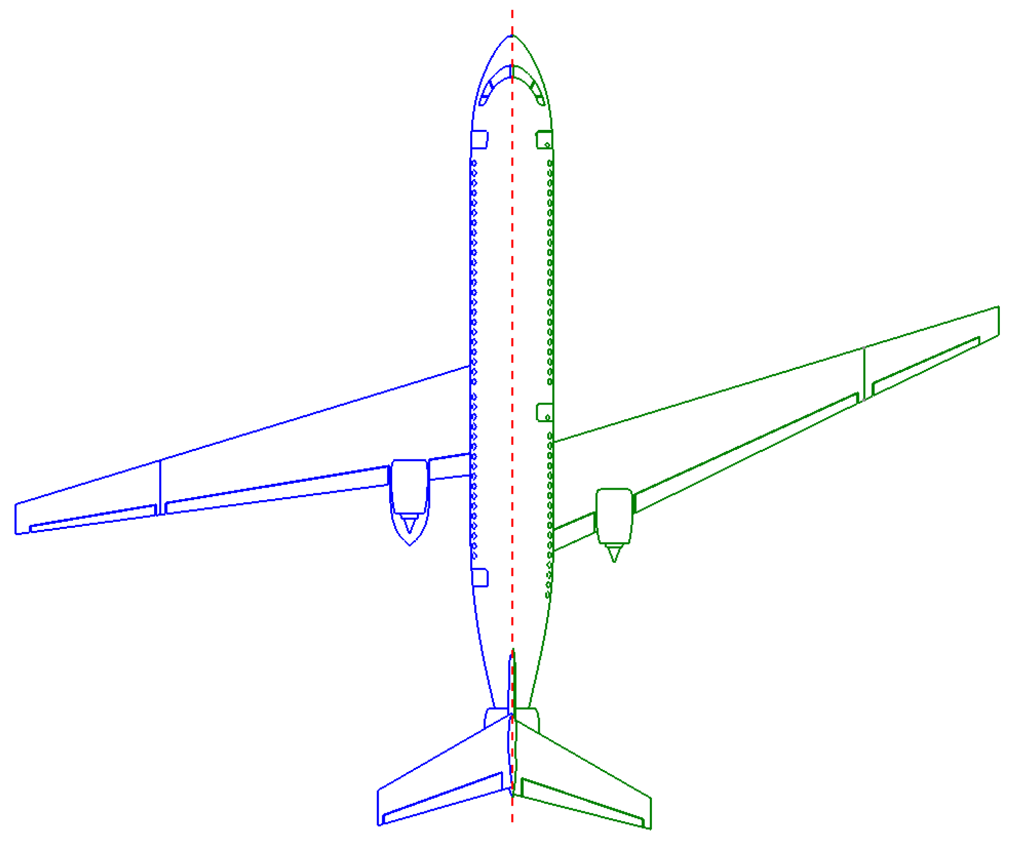
The aircraft is equipped with boundary layer suction (BLS), passive and active load alleviation, as well as novel materials and structures. The laminarisation of the wing is reached by using BLS technology. In particular, the different chord portion of laminar flow is studied, in order to analyze the possible variation of performance related to laminar flow. Empennage also features BLS similar to the wing, whereas the fuselage is laminar until the wing–fuselage junction. Laminarisation of the fuselage is reached via the application of the BLS until the wing–fuselage junction. The laminarisation effect on wing drag reduction is characterised in this paper with a drag penalties model, in particular, by using coefficients to reduce drag computed in full turbulent mode inside a gradient-based aerostructural optimisation framework (see Section 3.2 and Section 3). The study presents different values of maximum load factor (from 1.5 to 2.5) to take into account the effect of the load-alleviation technology for the future of aircraft design, allowing scenarios with different load limits to allow wing weight reduction [22]. Hence, the research is also characterised by lower values from the limit load factor of 2.5 obtained by using CS 25.337 [20]. The use of lower maximum-load factors as a way to take into account the effect of the technology in reducing weights during the optimisation is justified considering different research studies performed by using these assumptions to model the load-alleviation effect (such as [22,23]). Moreover, these values assume that load alleviation can counter gust and manoeuvre loads by a minimum of 20%, while flight safety in case of system failure is assured by using safety factors that are typically used for conventional aircraft [24]. High bypass ratio turbofan engines equipped with boundary-layer ingestion (BLI) were taken into account; in particular, two engines are positioned above the wing for noise shielding, and one engine is located at the fuselage to maximise BLI benefits. Two configurations were considered: the forward- and backward-swept aircraft (Figure 1). Both wing configurations present an absolute leading edge sweep of 17 degrees. DLR F15 airfoils were selected for the initial design. For initial design phases, wing thickness is distributed similarly to the A320 to avoid issues like insufficient volume to place landing gear. In addition, single-slotted Fowler flaps are chosen; no leading-edge devices are chosen because they could affect laminar flow capabilities. The designed aircraft is then refined with an optimisation process to reduce fuel weight (). The current research is based on a performance investigation of the two different configurations: the backward- and forward-swept aircraft. The reference geometric data are shown in Table 2.
3. Aerostructural Analysis
The coupled-adjoint aerostructural analysis and optimisation tool FEMWET [25] performs the aerostructural analysis. The tool consists of the coupling through the Newton method of the aerodynamic analysis, performed by a quasi-three-dimensional approach, and a structural solver characterised by a finite beam element model. In addition, FEMWET is modified to evaluate the effects of active flow control at different load cases inside a wing aerostructural optimisation framework for fuel weight reduction.
3.1. Structural Module
The FEMWET tool represents the core of the structural analysis [25]. The elastic wing is modeled as a finite beam located at its elastic axis. The choice of the beam model with respect to a shell relies on a tradeoff between accuracy and computational power. In fact, the accuracy could be improved by approximately 5% for a 2D-shell model but with a substantial increment of computational power [26]. The finite beam presents nodes located at the shear centers of each section. In addition, these nodes are characterised by the wingbox structural properties of the real wing model sections. The inputs of the tool are represented by the thicknesses of the wingbox equivalent panels. These thicknesses could be available in the literature, or an estimation tool, such as EMWET [27], can be used. In order to ensure that the thickness distribution chosen is physically applicable and able to sustain the loads, the FEMWET tool can run in aeroelastic mode, optimising the panels’ thickness for wing weight minimisation. The element stiffness, mass, and force matrices are obtained by using the consistent shape functions for a 3D Timoshenko beam. The structural governing Equation (1) is solved to obtain the displacement vector U.
In fact, the force vector F is known and the stiffness matrix K can be constructed once the wing box properties such as , , and , are computed at each node, considering the geometry, material, and structural properties of the real wingbox (more detail in [28]). Once U is determined, the stress distribution in the wingbox structure can be calculated. These stresses are used to determine the failure criteria due to material yield and to structural buckling. In detail, the stiffened panel efficiency method [29] is used for the stiffened panels such as the upper and lower equivalent panels. The shear buckling load failure is applied for the spars webs. The wing total weight computation is based on the equation from Kennedy and Martins [30], in which the weight is characterised by two terms (Equation (2)): the optimum wingbox weight from finite element analysis with a correction factor to take into account for weights not modeled in FEM, the secondary weight representing weights for leading edge, trailing edge, flaps, slats, etc.
Due to the use of novel materials and structures, 80% of the previous wing weight estimation is considered during the optimisation of the midrange aircraft analyzed in this paper.
3.2. Aerodynamic Module
The aerodynamic analysis is based on a quasi-three-dimensional (Q3D) [31] aerodynamic solver. The tool has been modified for an aerostructural coupling in the optimisation framework. The lift distribution on the wing is computed by using the vortex lattice method (VLM) based on the methodology developed by Katz and Plotkin [32], and the strip theory [33] is used to calculate viscous drag at different spanwise positions. The VLM computes the wing lift distribution, the wing lift coefficient , and the wing-induced drag coefficient through the Trefftz plane analysis [34]. In particular, from the wing geoemetry and the angle of attack, the aerodynamic influence coefficients () matrix and the right-hand side () vector are obtained. Considering the governing equation
The strengths of the vortex rings () can be calculated, and consequently the Kutta–Joukowski theorem can be applied to determine the wing lift distribution. The Prandtl–Glauert compressibility correction is used for high Mach number conditions. The lift distribution obtained by the VLM is interpolated to find the at a given spanwise section. Sweep theory is applied to obtain , Mach number, and velocity, normal to the sweep line. Considering that pressure drag acts perpendicularly to the shockwave line, a sweep line coinciding with the shockwave [35,36], for transonic regime analysis, is chosen. Hence, a half-chord sweep angle is used. The effective velocity and Reynolds are then evaluated and become the input of 2D airfoil analysis, the MSES tool [37], to compute the effective angle of attack and effective drag parameters. MSES is an interactive viscous/inviscid Euler method, useful for single- and multielement airfoils that can predict compressibility drag and hence are suitable for transonic regime application. Moreover, it can predict boundary-layer separation and transition and investigate the effects of geometry changes [38]. In this research, the Chebychev polynomials are used to parameterize the airfoil geometry. MSES is able to compute the derivatives of the output, such as lift or drag, with respect to the input, such as angle of attack, Mach number, and Reynolds number.
The original Q3D method of FEMWET is modified to consider active flow control via BLS. The boundary-layer transition from laminar to turbulent can happen due to three general sources of instabilities: Tollmien–Schlichting instabilities (TSI), cross-flow instabilities (CSI), and attachment line instabilities (ALI). Boundary-layer suction consists of the removal of a limited portion of the boundary layer in the wall region and hence a delay of the flow turbulent transition dampening the instabilities. In general, to accurately simulate the behavior of the boundary layer with the presence of suction, a modification of boundary-layer equations is required. An example of integration of the BLS into the boundary-layer modeling is given by the tool XFOILSUC, where the airfoil panel method code XFOIL [39] was modified. Because the possibility of working on the source code of MSES is discouraged due to license limitations, the aerodynamic module cannot perform a high-fidelity analysis of the boundary-layer suction. Moreover, additional integrations of simulation techniques may significantly reduce the time efficiency of the solver, which makes the medium-fidelity analysis more complicated and time consuming, especially in the early design stages. Therefore, the present work suggests the use of preestimated drag penalty coefficients to approximate the reduction of drag by active flow control as a lower-fidelity treatment of the laminar flow control technology.
Finally, the profile drag coefficient is obtained in the streamwise direction. The wing total drag is calculated by integrating the parasite drag coefficient (including the wave drag as part of the pressure drag) of the 2D sections over the span and addition of the induced drag components, as shown in Equation (4),
The BLS affects friction and form drag only, which are included inside the integral term of Equation (4). Therefore, the integral term needs to be corrected to account for the drag reduction introduced by the suction. In the stated equation, other drag components are not affected by the suction and do not require any additional corrections. For the analysis, MSES is run with a fully turbulent flow over each airfoil along the wing and the transition of the upper and lower airfoil surfaces is fixed at 3% of the chord. Then, a series of coefficients is applied to the parasite drag components calculated by using the full turbulent case to simulate drag reduction by active flow control. Hence, the drag computation obtained by Q3D is based on the penalty model, as the calculation of derivatives necessary for the gradient-based optimisation. The modified drag equation of the wing then becomes
where and correspond to the friction and form drag (pressure drag-wave drag) correction factors, respectively.
Because capabilities of modeling the suction of the boundary layer are not currently available for MSES, a statistical representation of effects of the active flow control are introduced in the present work to estimate values of and . If common trends with respect to the drag reduction potential due to suction are found for a sufficient number of airfoils, then it can be assumed that designed airfoil suction will be likely to share similar drag-reduction properties. To obtain the database of airfoil drag characteristics for supercritical airfolis, MSES is run with several user-defined fixed transition locations for a number of different supercritical airfoils at various flight conditions. In particular, seven supercritical airfoils are chosen: DLRF15, RAE2822, Whitcomb integral, SC(2)0410, Nacalangley symmetrical, Lockheed–Georgia, and the KC-135 winglet. Each airfoil is scaled for different maximum airfoil thickness: 9.5%, 10.5%, 11.5%, 12.5%, 13.5%, and so on for a total of different 35 airfoil cases. A population of 10 elements for flight conditions is determined considering the Latin hypercube sampling, for , , million. All 35 airfoil cases are tested for each flight condition, for a total of 350 cases. Each case is tested for fixed transition at the top and bottom surface: Xtr = [2% 5% 10% 15% 20% 25% 30% 35% 40% 45% 50%], evaluating 3850 tests. To ensure high confidence of the obtained database, data need to be cleaned by deleting nonconverged cases or cases in which transition is different from the values established in the vector ; otherwise, the analysis would be inconsistent and the considerations affected by the diversity. Finally, cases with
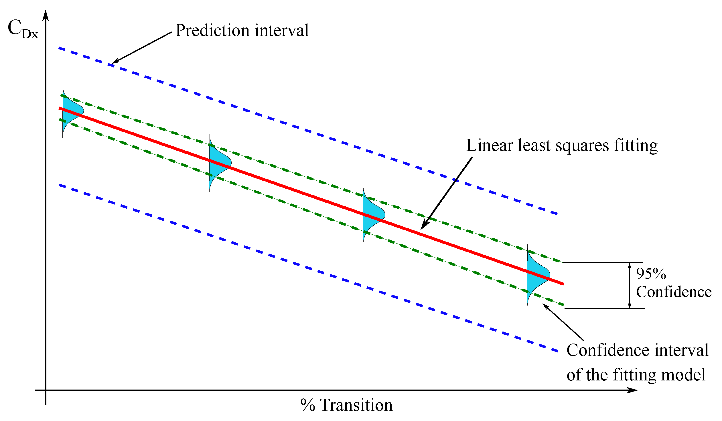
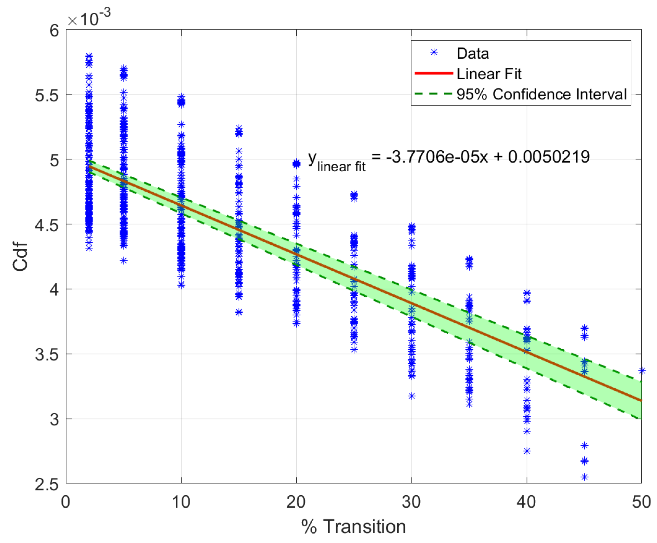
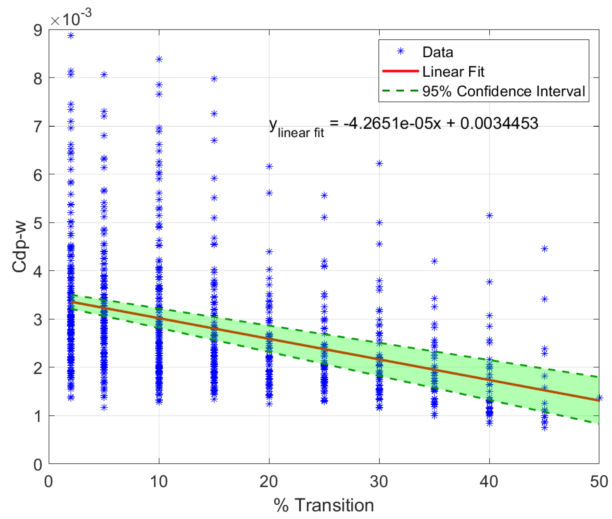
are discarded for static pitch stability condition. Data are then statistically treated for a total of 846 samples. In particular, the goal is to find proper drag penalty coefficients that can be applied by considering the parameters’ variation during the optimisation, such as geometry and effective flight conditions. In fact, during the optimisation, a variation of the sweep angle or taper ratio can imply a modification of the effective Mach number and Reynolds, or, in general, the weight variation is related to a different lift coefficient. The authors want to find coefficients able to approximately compute drag reduction as an average with respect to all possible conditions. The use of specific coefficients for specific conditions, rather than average scenario, would imply a substantial increase in the complexity of the framework and consequently of the computational power, not compensated by the advantages of a drag penalty approach. To ensure the robustness of the approach with the presence of parasite drag variations for each airfoil and flight condition, a linear least-squares fitting is applied considering a 95% confidence interval, as shown in Figure 2. Figure 3 and Figure 4 show the linear fitting of the friction and form drag (pressure minus wave drag) respectively, obtained as a best fit, in a least-squares sense, for the data in y. In this way, it is possible to predict the chosen drag coefficient for different positions of fixed transition, simulating laminar flow. The green band represents the 95% confidence interval, which in turn represents the uncertainty of the fitting model studied rather than the prediction bounds (represented as an example in the blue dashed lines in Figure 2); this shows where a new test drag could potentially be. In the present research, we are interested in the uncertainties related to our fitting model, including how the fitting curve could be shifted depending on new data. The narrower the confidence band, the greater the accuracy given by the model in estimating coefficients to be applied for drag correction to take into account laminar flow.
3.3. Aerostructural Coupled System
The aerodynamic module characterised by the Q3D application is integrated into FEMWET. The aerostructural system is characterised by the following four systems of governing equations:
In detail, Equation (7) indicates the governing equation of the VLM (see Section 3.2). Equation (8) expresses the structural finite element model (see Section 3.1). The third equation states that the total lift needs to be equal to the design weight for a given load case and consequently multiplied by the proper load factor. In particular, in the present work, the design weight is defined as for cruise condition. The last equation guarantees that the lift distribution obtained by the strip theory through the drag analysis tool (MSES for the current research) is equal to the lift computed from the VLM once the corrections for sweep are applied. The coupled system is solved by using the Newton method, the advantages of which are given by a consistent solution together with the saving of computational time in building the gradient for the optimisation. In fact, the derivatives used for the convergence of the solution can be also used for the optimisation. During the Newton iterations, the design vector X is kept constant, the updates on the state variables are obtained by the system of equations in (11).
where the matrix J is defined by:
3.4. Aeroelasticity
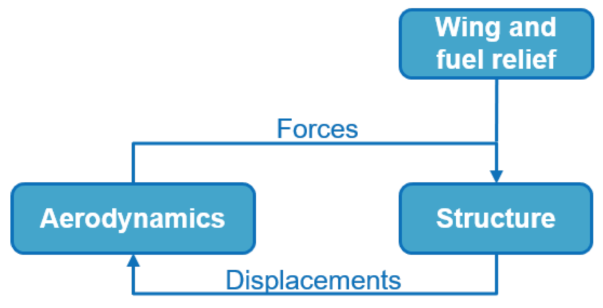
Aeroelasticity represents the core of this work. In particular, it is considered as the interaction between the aerodynamic, inertial, and elastic forces, and its influence needs to be taken into account during the design process as early as possible, especially for unconventional aircraft. In fact, the aerodynamic loads acting on the structures need to be estimated properly to satisfy the failure criteria, taking into account that the flexibility of the structure will generate different and separate loads that again influence the aerodynamics in a continuous interaction. The aeroelastic phenomenon characterising the interaction between aerodynamic, inertial, and elastic forces is generally referred to as dynamic aeroelasticity, whereas the simplification including just the aerodynamic and elastic components is called static aeroelasticity (Figure 5). Static aeroelasticity presents the elimination of time as an independent variable, and consequently vibratory inertial forces are removed from the equilibrium equations. The aerodynamics are based on steady flow instead of the more complex unsteady flow theory [40]. Two main problems related to static aeroelasticity are divergence and aileron reversal, which are studied in this article, whereas dynamic aeroelasticity is the subject of future work.
3.4.1. Static Aeroelasticity: Divergence
Divergence is considered to be the first issue to investigate in static aeroelasticity because of its “destructive” nature. In fact, it occurs at moments when aerodynamic forces overcome the restoring moments due to structural stiffness, consequently resulting in structural failure [41].
The general dynamic problem is described by Equation (13):
In this equation, is the generalized displacement vector, whereas , , and are the modal mass, damping, and stiffness matrices, respectively. The vector is the modal aerodynamic force vector. Considering the static problem, Equation (14) becomes
The aeroelastic stiffness matrix can be defined as , in which represents the structural stiffness matrix, q is the divergence pressure, and is the aerodynamic stiffness matrix. The vector F can be rewritten in the form of , in which the aerodynamic stiffness matrix represents the generalized aerodynamic force matrix on the modal coordinates system [41,42]. The problem can be solved as an eigenvalue problem for static aeroelastic stability, in which the solution of Equation (15) gives a set of eigenvalues. The minimum real positive eigenvalue gives the critical dynamic pressure for which the system is no more statically stable, and hence, from this pressure, the divergence speed can be computed.
The wing sweep angle may influence the phenomenon. A backward-swept wing is less subject to the problem, shifting the divergence speed for higher values because of the reducing effect on the incidence. In contrast, in a forward-swept wing, an upward bending of the wing produces in all the sections in line of the flight stream an increase of the angle of attack, which, in turn, leads to additional lift forces [41]. A possible solution, in addition to the increment of wing weight, is the use of a structural layout of the wingbox with fiber composites, so an aeroelastic tailoring can be applied. Carbon fiber-reinforced plastics (CFRP) present anisotropic characteristics that allow the coupling between the flexional and torsional wing deformations. In fact, proper fiber direction permits a rotation of the wing sections parallel to the flow counteracting the upward bending [43]. In this research, divergence instability is checked during optimisation by the convergence of the Newton loop for the coupled system described in Section 3.3. In fact, the iterative system needs to satisfy a tolerance and a certain maximum number of iterations to have a solution for the aerostructural system; if this is not possible, an error warning for the instability is displayed, and the optimisation is stopped.
3.4.2. Static Aeroelasticity: Aileron Reversal
Another static aeroelastic phenomenon is the aileron reversal. It is not necessarily disruptive but it may affect the controllability of the aircraft and even be dangerous. When a deflection of the aileron is applied, a roll moment is generated to allow the roll manoeuvre, and a torsional moment is produced, leading to an elastic twist deformation of the wing. This twist deformation can reduce the efficiency of the deflection and even reverse its effect. The aileron effectiveness, defined as the ratio of elastic to the rigid roll moment of the wing due to an aileron deflection, represents a constraint for the wing aerostructural optimisation:
Two different effects can be distinguished: the possibility of reversal on backward-swept and forward-swept configurations. In fact, the backward-swept wing is more sensitive to this effect. The backward-swept configuration is prone to a reduction of the twist because of the aerodynamic effect generated by the wing deflection. The effect reduces the effectiveness of the wing in rolling; the higher the speed, the greater is the dynamic pressure and the greater is the detrimental effect on the control effectiveness.
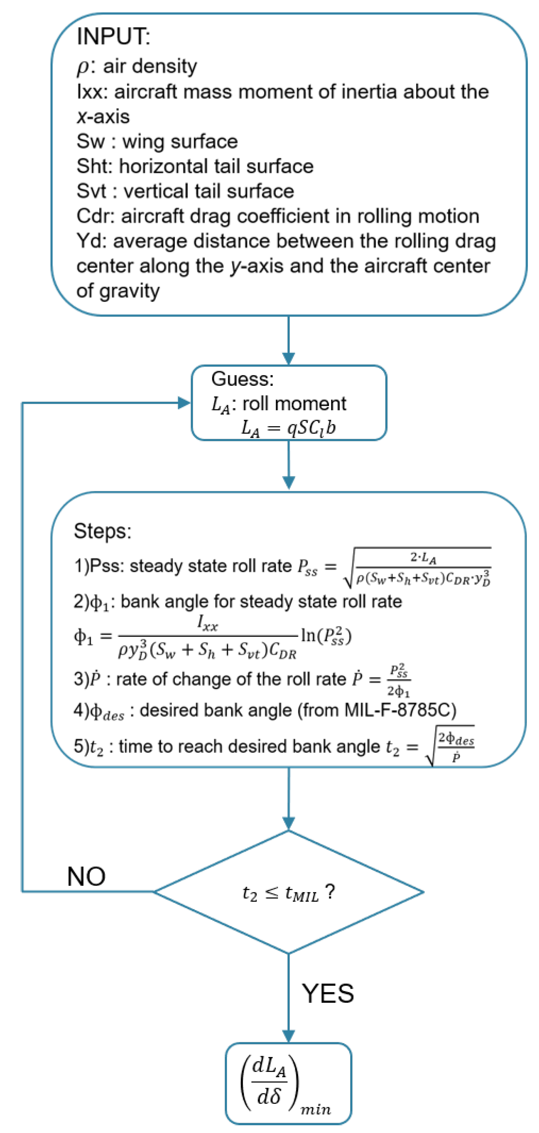
In this case, the flexibility of the wing reduces the controllability of the aircraft respective to the rigid case [41]. The forward-swept wing presents the opposite behaviour—the bending of the wing due to a downward deflection of the aileron, and hence under an upward load produces a nose-up deflection. In addition, the deflection produces a pitching moment that twists the section in opposition to the previous effect [40]. Finally, the control effectiveness may be relatively affected or even favored, as shown in [44], in which the aeroelastic effects of a forward-swept composite wing are studied for different values of dynamic pressure, presenting . In this study, reversal is avoided by considering a constraint during the optimisation, represented by the minimum of the derivative of the roll moment with respect to aileron deflection, defined as (see Section 4). Figure 6 shows the scheme used to calculate the derivative of roll moment due to aileron deflection (); in particular, the process is obtained by reversing the methodology developed by Sadraey [45] for the aileron design. The idea is to consider a steady-state roll maneouvre and the bank angle obtained for the steady-state roll rate. The flexible wing roll moment is taken as a guess value, starting from the moment obtained considering an aileron effectiveness and multiplying this value by the rigid roll moment calculated by FEMWET. The guess is based considering the chosen for a Boeing 747-100 in [46] and for the A320 analyzed in [25]. Once these parameters are known, the rate of change of the roll rate is computed, and then the time arrives to reach a desired bank angle.
In this case, aircraft certifications laws are needed, in order to satisfy roll performance. This research uses the MIL-F-8785C [47] to set the desired roll capacity. Considering the maximum takeoff weight (MTOW) of the cases analyzed in this research, a Class III is chosen, and flying qualities clearly adequate for the mission (meaning Level 1 and Category A) are chosen for conservative reasons. Hence, the desired bank angle is 30 degrees to perform in a maximum of 2 s.
3.5. Sensitivity Analysis
To facilitate the gradient-based optimisation, a coupled-adjoint approach augmented by automatic differentiation is used in FEMWET for analytical sensitivity analysis. In this approach, the total derivative of a function of interest I with respect to a design variable x is computed as
where the adjoint vector is represented by
computed by the following equation:
Equation (19) is characterised by the matrix of partial derivatives of the residual respect to the state variables, equal to the matrix J used in the Newton loop (Equation (11)). Once the matrix J is generated in the Newton iteration, as a consequence it can be used for the adjoint vector calculation. As seen in Equation (17), the total derivative is characterised by partial derivatives of I with respect to the design variable x, partial derivatives of residuals, from R1 to R4, with respect to x, the partial derivatives of the function of interest I, with respect to the state variables; all these partial derivatives are obtained by a combination of analytical methods and AD. More details about the sensitivity analysis can be found in [25].
3.6. Performance Module
The fuel weight necessary for the mission is evaluated through the methodology presented by Roskam [48]. In detail, the required fuel for the cruise is calculated by using the Breguet equation and some statistical factors to estimate other flight segments. The total fuel weight fraction represents the consumed fuel as the ratio between the total aircraft weight at the end of the mission and at the beginning.
For fuel weight estimation, the lift over drag ratio needs to be computed. The drag is calculated considering two terms: wing drag and drag of the rest of the aircraft. The drag of the rest of the aircraft is kept constant because the optimisation involves the wing only. Hence, the first step is to compute the cruise drag obtained by using the initial from the preliminary design. Then, FEMWET is used to obtain the wing drag and by subtracting from the cruise drag, the rest of the drag can be determined. The aircraft range, cruise Mach number, cruise altitude, and the engine parameters are assumed to be constant. The fuel weight () also includes a 5% of the total fuel weight as reserve fuel [20].
3.7. Validation
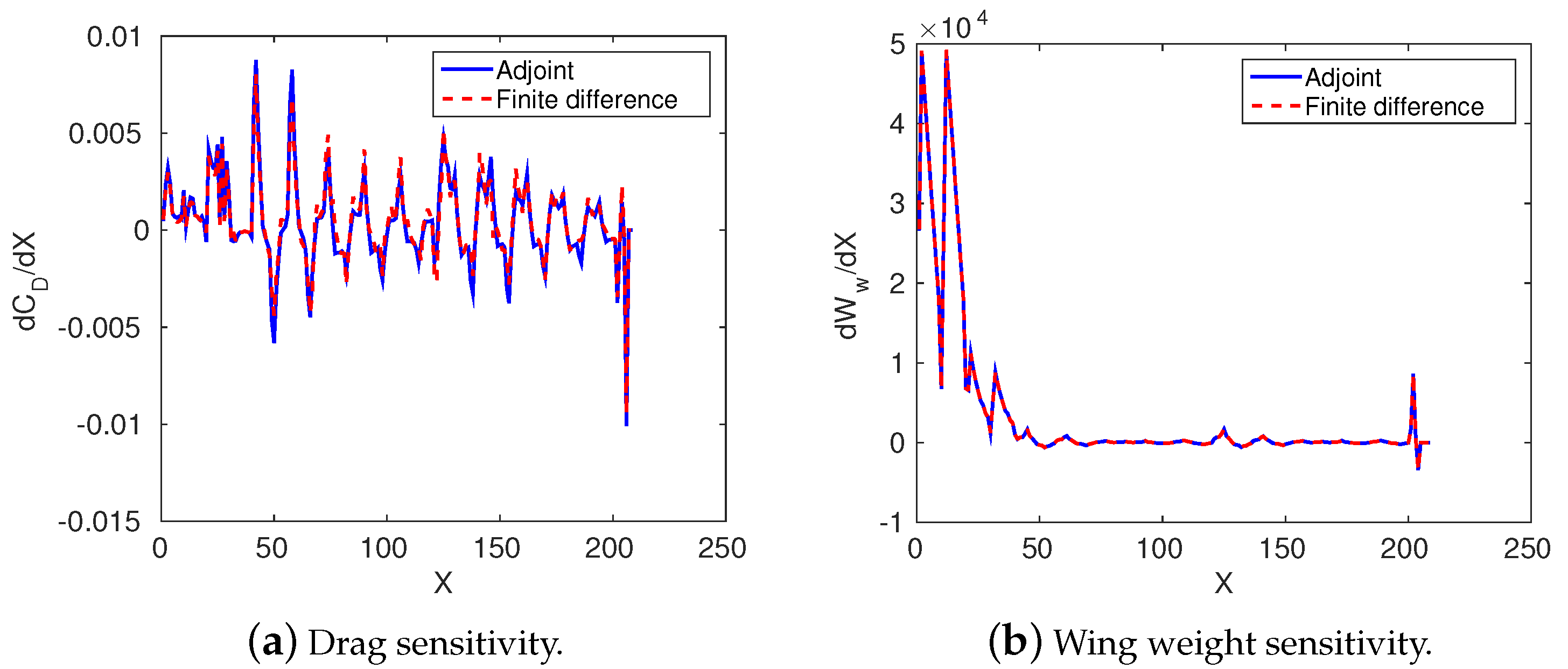
FEMWET has been validated by considering three different aspects: accuracy of the wing drag computation, estimation of the wing deformation, and verification of the adjoint sensitivity analysis. The validation has been performed in [25]. Good accuracy of Q3D in the drag prediction is shown by using a higher-fidelity CFD tool: MATRICS-V code [49]. The tool presents a full potential code in a fully conservative finite volume scheme. The estimation of viscous drag is obtained through the coupling with a boundary-layer solver. Wave drag is characterised by the volume integration of the artificial viscosity [50]. When considering data regarding wing twist under a 1g load in A320-200 aircraft in [51], FEMWET presents an error of −0.12% in the wing weight calculation, considering an aeroelastic optimisation that provides the thickness of the equivalent panels. The deformation of the same aircraft at 1 g load case shows a maximum error of 8.5% at the wing tip. The validity of the use of the adjoint method, used for the gradient-based optimisation, is explained in detail in [25], in which different derivatives of functions of interest with respect to design variables are computed and compared with respect to the finite difference method. Considering the new modified drag model introduced in the aerodynamic module to take into account penalties in drag computation for the estimation of the active flow control, a sensitivity analysis comparing the adjoint and finite difference methods, is implemented (Figure 7). Figure 7a shows the good accordance of the two methodologies; the minor mismatch is due to the limited precision of the drag output computed by MSES. In fact, the wing weight sensitivity, not subjected to MSES, presents a perfect match between adjoint and finite difference technique (Figure 7b).
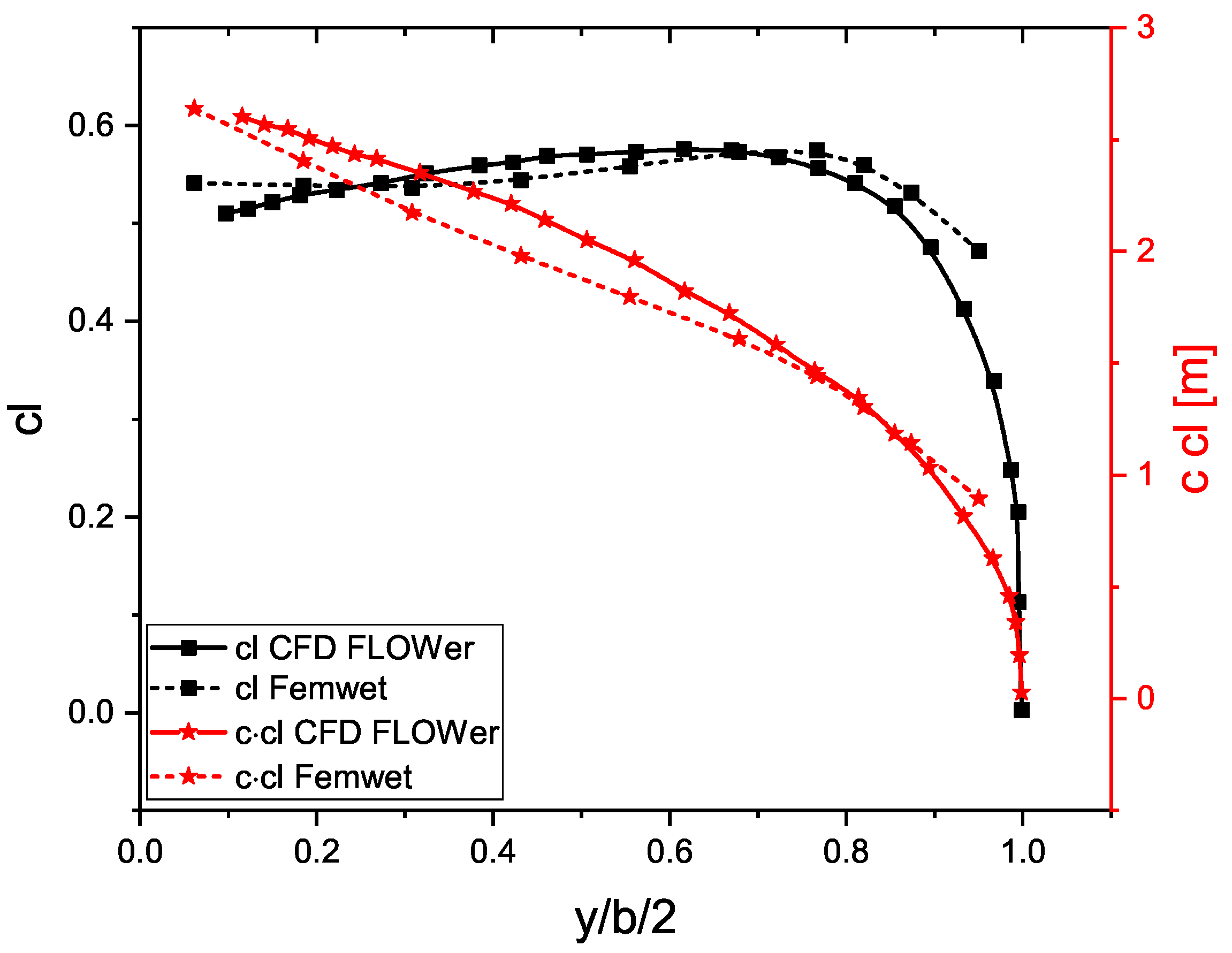
In Table 4, two different test cases are used to verify the reliability of FEMWET to compute drag considering active flow control and hence use the penalties defined in Section 3.2. The first case consists of the HLFC airfoil designed by Sudhi et al. [16], in which an airfoil for a transonic regime application is studied, equipped with leading-edge suction. Midfidelity tools are used to extract boundary-layer characteristics and transition prediction, in particular the boundary-layer and linear stability theory solvers Coco-Lilo [52,53]. They contribute to the viscous drag computation, whereas the wave drag is estimated by MSES. Updated data shows a profile drag of 33.2 drag counts with transition at 64% at the upper surface and 49% at the bottom. The difference of 1.6 drag counts with respect to FEMWET is justified considering that the strategy developed to design the airfoil is to consider the portion of wave drag as equal to what was obtained by the natural laminar flow condition for the same airfoil. By contrast, the aerodynamics studied in FEMWET (Section 3.2) rely on a turbulent analysis and hence the wave drag, not influenced by the active flow control, is higher. In addition, the use of drag penalty coefficients are meant to be used for a complete wing configuration instead of a single airfoil, as an average for different flow conditions from root to tip and differences that may arise during the optimisation. The second case is represented by the TuLam aircraft [43], in which the German DLR studied a transonic laminar flow forward-wing aircraft for cruise condition. The viscous drag is in good agreement with respect to FEMWET, analysed for M = 0.78 and Cl = 0.52 by using the DLR Reynolds-averaged Navier–Stokes (RANS) solver FLOWer [54]. A minor difference is expected because of the difficulties in defining all the input data necessary for FEMWET, in particular, the lack of airfoil coordinate availability forced the authors to rebuild it from [43]. In addition, the wingbox panel-thickness distribution used is the same as that of the A320, because of the lack of detailed information.
The lift coefficient () and the distribution shown in Figure 8 are in good agreement. To validate the accuracy of FEMWET for structural analysis of forward-swept wings, the wing of [43] is considered. An aeroelastic optimisation with FEMWET is executed for the wing geometry and load case of [43], to compute the structure thicknesses and consequently the wing weight. FEMWET estimates a wing weight of 7249 kg, with just a difference of 11 kg (−0.16%) with respect to [43].
4. Multidisciplinary Design Optimisation
As already stated in the paper, a gradient-based optimisation is performed to minimize the fuel weight of the SE2A midrange aircraft. The multidisciplinary design problem is defined as
The design vector is:
The first four components defined in Equation (21) represent the thicknesses of the upper and lower equivalent panels, and front and rear spars. These thicknesses are referred to in 10 different sections, going from root to tip, reaching 40 total variables. The G vector consists of the modes used for the Chebyschev polynomials to parametrize airfoil shapes. Ten modes are used for the upper surface and 10 modes for the lower one, for a total of 160 variables taking into account eight different sections. The wing geometry is defined through the root chord, taper ratio, span, sweep angle at the leading edge, and twist angle at kink and tip. In this research, the midrange aircraft is presented as a trapezoid wing without a kink. Hence, the twist variable is defined at 25% of the span and at the tip. Finally, two surrogate variables are introduced to avoid iterations during aeroelastic analysis: fuel weight and maximum takeoff weight.
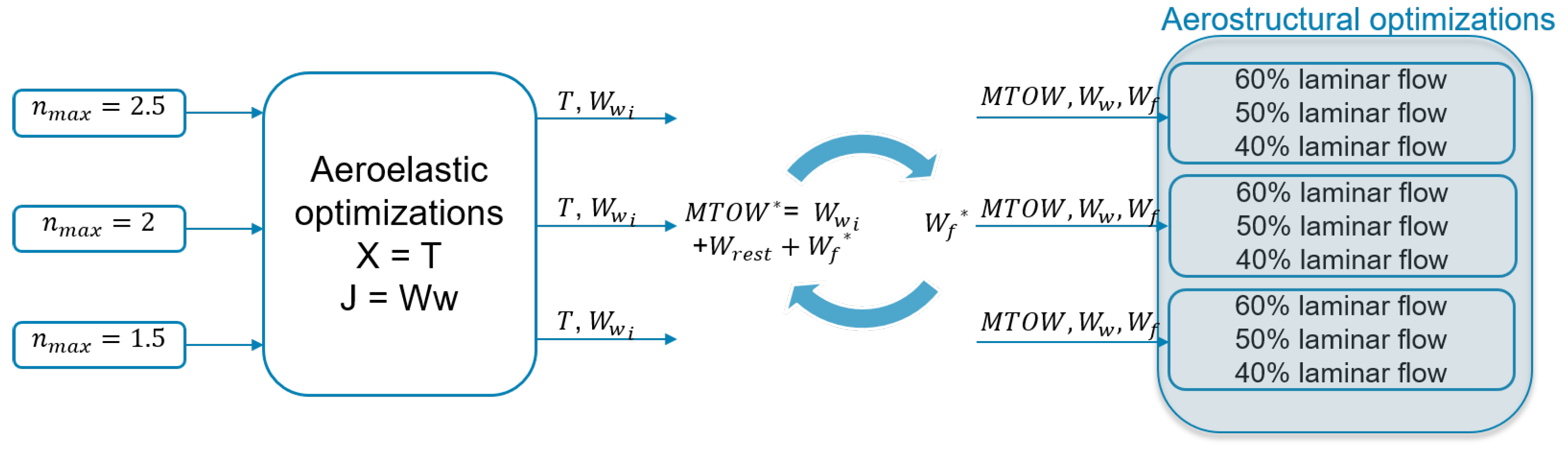
Prior to the full aerostructural optimisations, preliminary aeroelastic optimisations, characterised by panel thicknesses as design variables (first four components of the design vector X), are executed. Different maximum load factors are selected as input. The aeroelastic analyses allow with limited computational time to optimise the wingbox panels minimising . Once the final wing weight is obtained, the MTOW is updated, initially keeping the fuel weight similar to the preliminary one. Finally, and MTOW are iteratively updated until convergence.
Both the aerostructural and aeroelastic optimisations present different constraints. From a structural point of view, constraints on structural failure, related to tensile, compressive, and buckling loads, are applied. For this reason, five different load cases are evaluated (Table 5): two pull-up maneuver cases at maximum load factor (), which vary depending on the hypothetical load case scenario considered, a -1g push over maneuver, a 1.3g gust load to simulate the fatigue of the wing lower panel, and a roll maneuver to compute the aileron effectiveness. Finally, the cruise flight condition is also evaluated for the performance estimation. All conditions are determined based on flight envelope and load diagram studied in preliminary aircraft design of the aircraft [21].
The aileron effectiveness, defined as the ratio of the elastic to the rigid roll moment of the wing due to an aileron deflection, represents a constraint to satisfy the requirements on the roll performance. The roll performance is not only a function of the aircraft roll moment but also of the aircraft moment of inertia. In particular, during the aerostructural optimisation, the planform geometry will change, thus changing the two variables. The minimum of derivative of the roll moment respect to aileron deflection, used as a constraint of the optimisation, is set following the procedure clarified in Section 3.4.2. Wing loading (MTOW/S or W/S) shall be lower than or equal to its initial value. In this way, the aircraft can satisfy the takeoff and landing requirements. The last constraint is given by the the fuel volume required that needs to be lower than or equal to the available volume. This constraint is expressed in terms of the required fuel computed by the surrogate variable and the available fuel as . In total, three different aeroelastic optimisations are performed, so that different maximum load factors can minimise wing weight by varying the thicknesses of the wingbox panels.
These are the inputs of some iterative cycles which set final weight values as new inputs of nine different aerostructural optimisations (three optimisations for each maximum load factor), the objective function of which is represented by fuel weight and all the characteristics shown in Equations (20) and (21). The whole optimisation framework is clarified in Figure 9.
5. Results
Backward- and forward-swept configurations are optimised according to Section 4. Each configuration presents three aeroelastic optimisations for preliminary sizing, an iterative cycle to update variables, and consequently nine aerostructural optimisations divided into three groups depending on the maximum load factor and the percentage of laminar flow along the wing. A total of six aeroelastic and 18 aerostructural optimisations are performed. Final results of the forward-swept configuration are presented in Table 6, and the output of the backward-swept is shown in Table 7. The reference configuration is characterised by the output coming from the aeroelastic optimisations as defined in Section 4 and shown in Figure 9. The aeroelastic optimisations are initialised by the low-fidelity design coming from low-fidelity tools implemented for the mission analysis and to satisfy the requirements in Table 1. In Table 6, considering the same condition of laminar flow for the forward-swept analysis, the configuration presents higher drag, lower , and hence higher fuel weight. The other components of the weights are also subject to increments with respect to the optimised versions.
Table 7 shows the results of the backward-swept configuration. In this case, the trend of weight reduction needs further investigation. In fact, although the forward-swept configuration (going from a higher portion of laminar flow to a lower one) induces a progressive augmentation of the weights (MTOW, ), in the backward-swept case this is not always respected. The reason behind the phenomenon is the choice of the optimiser to balance between aerodynamic and structural benefits, so even if structural weights may be incremented for higher % laminar flow, the ratio plays the main role in minimising .
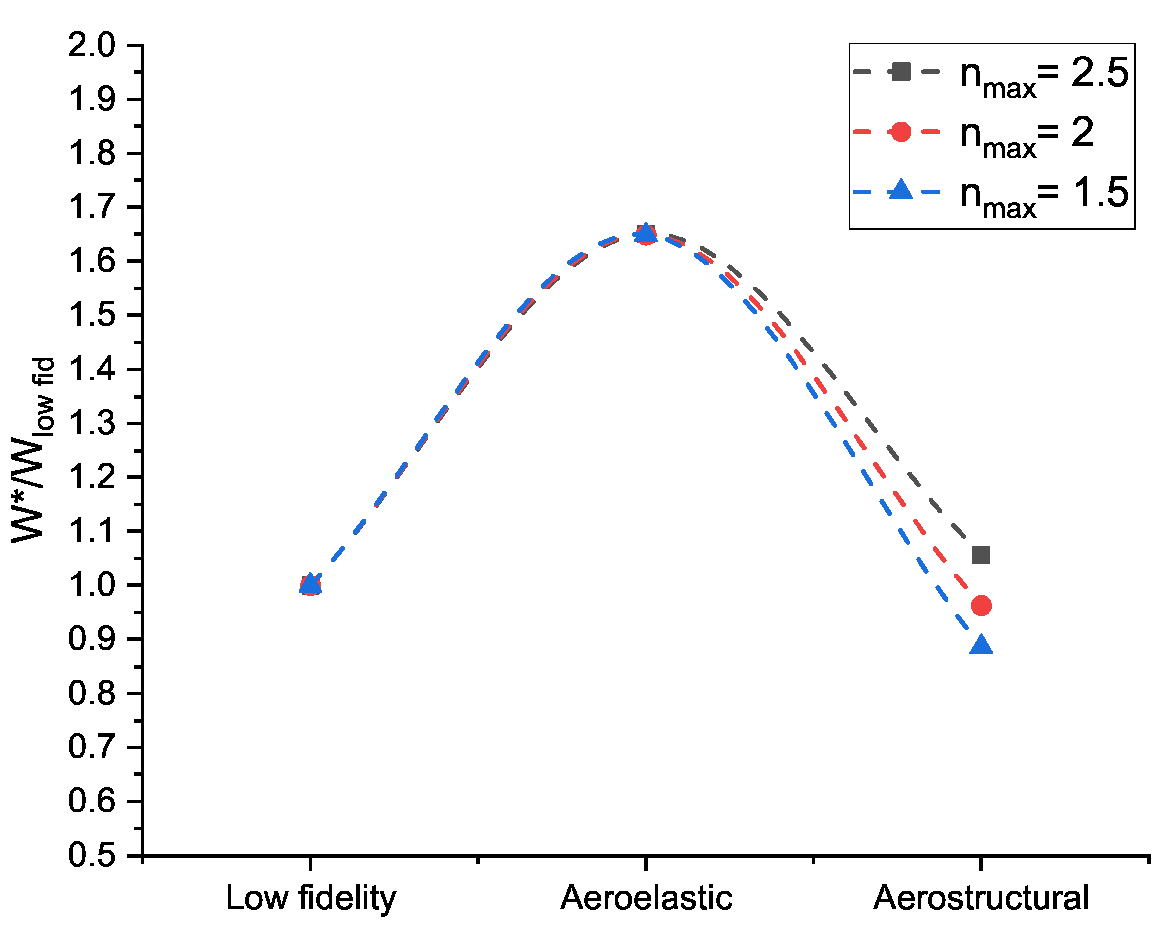
Figure 10 shows an example of how the wing weight changes from the reference data given by low-fidelity studies to aerostructural optimisation. Low-fidelity analysis did not consider aeroelastic effects, aileron reversal, or a deep analysis of wingbox panel thicknesses. Hence, during the aeroelastic optimisation, thicknesses are distributed properly to satisfy material failure and to make the wing statically stable with proper roll capabilities. In particular, the backward-swept configuration is more subject to reduced roll capabilities and aileron reversal compared to aeroelastic divergence. As a consequence, because the preliminary aeroelastic optimisation had constant airfoil shapes and planform characteristics, the weight increment is significant. Once the aerostructural optimisation is performed, depending on the condition, some weight reduction can be achieved with respect to the initial low- fidelity used as reference for this specific analysis. The wing weight obtained after aeroelastic optimisation has a minor variation with the changing of , and the effect becomes slightly higher for the aerostructural optimisation. In fact, the main driver, especially for a backward-swept wing aircraft, is given by the aileron effectiveness constraint.
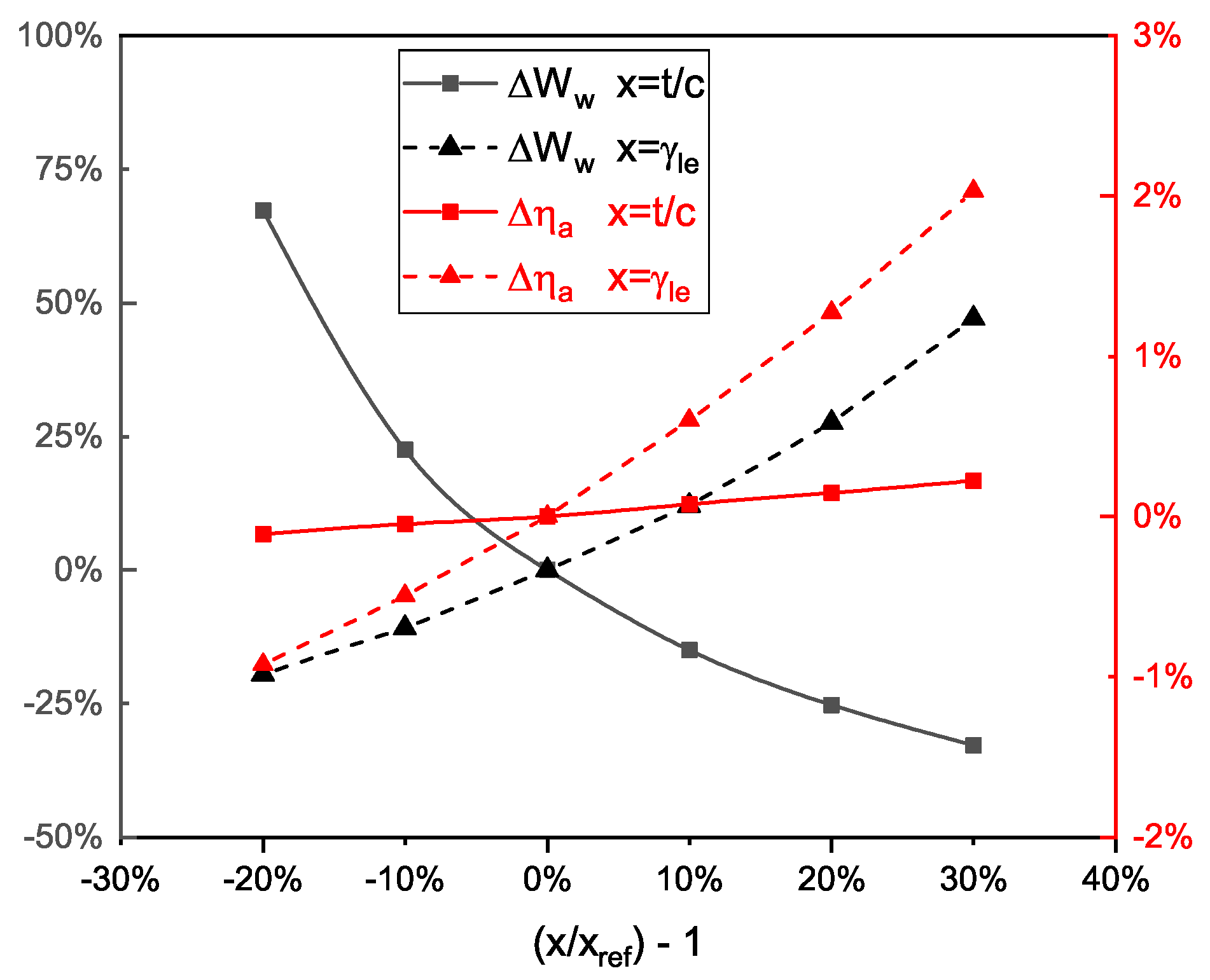
This trend justifies the higher percentage reduction of weights for the optimised configuration of the backward-swept wing (Table 7) with respect to the forward-swept one (Table 6). In fact, the backward-swept configuration needs to increment its weight to satisfy the roll requirement and change the panel thicknesses accordingly. A similar trend is described in Ref. [28], where it is demonstrated that wing structural weight varies quadratically with the aileron effectiveness. In contrast, the forward-swept case does not present any roll issues because of its nature (as discussed in Section 3.4.2), the requirement is easily satisfied without implying particular needs of the final optimised configuration. The little increment of weight is needed for aeroelastic reasons, but the reduced aspect ratio compared to the backward-swept configuration allows it to avoid excessive weight increments and helps the wing stability. Considering the reference backward-swept low-fidelity aircraft, optimised aeroelastically for wing weight reduction via resizing the wing structure box, Figure 11 shows the influence of the airfoil thickness, scaled from its reference value, on the aileron effectiveness and wing weight . If the airfoil is scaled toward higher thickness, a decrement of is obtained because of the higher stiffness of the larger sections helping in sustaining loads. The aileron effectiveness is slightly augmented, and the increment is more marked for a higher leading edge sweep angle . A higher sweep brings higher due to higher loads.
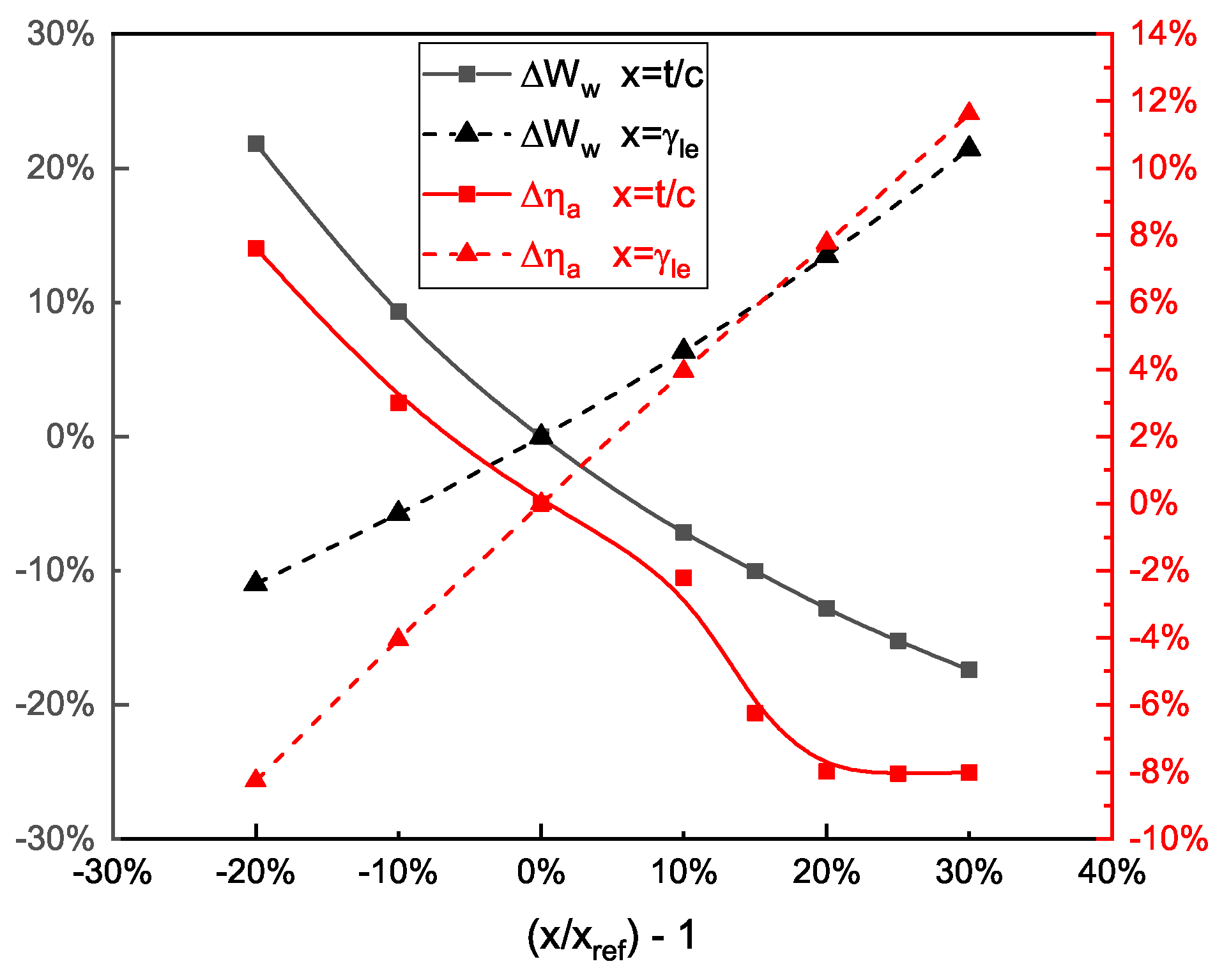
The influence of the above parameters on the forward-swept configuration is studied in Figure 12.
In particular, a higher makes the optimised wing lighter, whereas higher sweep increases the . The aileron effectiveness has benefits on the increment of , in fact, as seen in Section 3.4.2, the forward-swept case has more benefits in satisfying roll requirements and the consequential increment of the negative angle increments the benefit. An opposite trend is shown for thickness augmentation; in fact, the bigger section is affecting the aeroelastic deformation negatively via partially reducing the aileron effectiveness. A plateau is spotted for higher ; hence, to confirm this behaviour, two more design points are investigated, at , and a B-spline curve fitting is used to take into account its variation, while approaching the plateau. It is noticeable that for the forward-swept wing, variations of are higher in absolute values with respect to the backward-swept case. In fact, the forward-swept configuration has no issues in satisfying the aileron constraint for its geometrical nature, allowing more freedom of the optimiser. Finally, the full aerostructural optimisation allows complete freedom in reaching the final configuration, because of the full set of design variables going from thickness of the wingbox panels to airfoil shape and wing geometry.
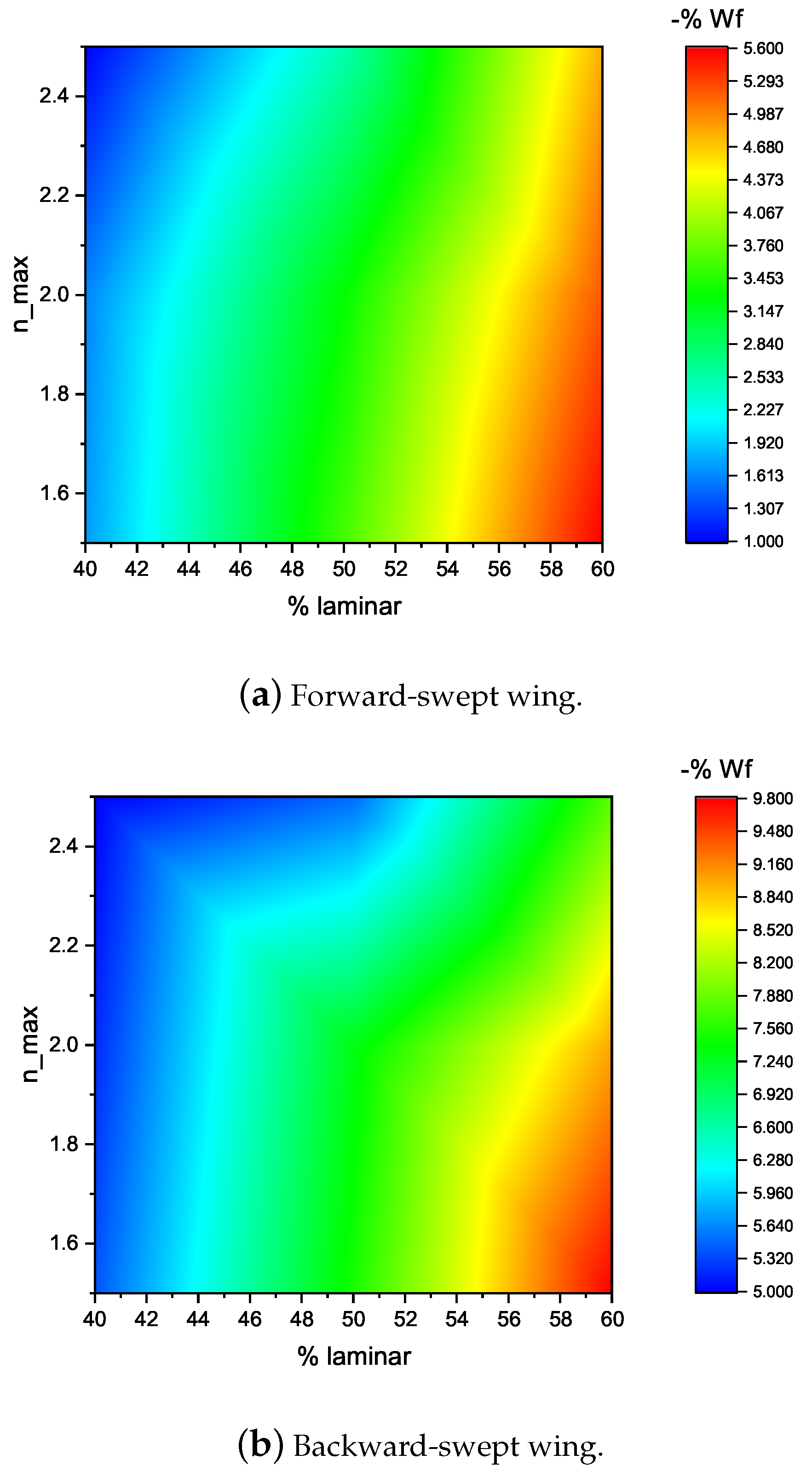
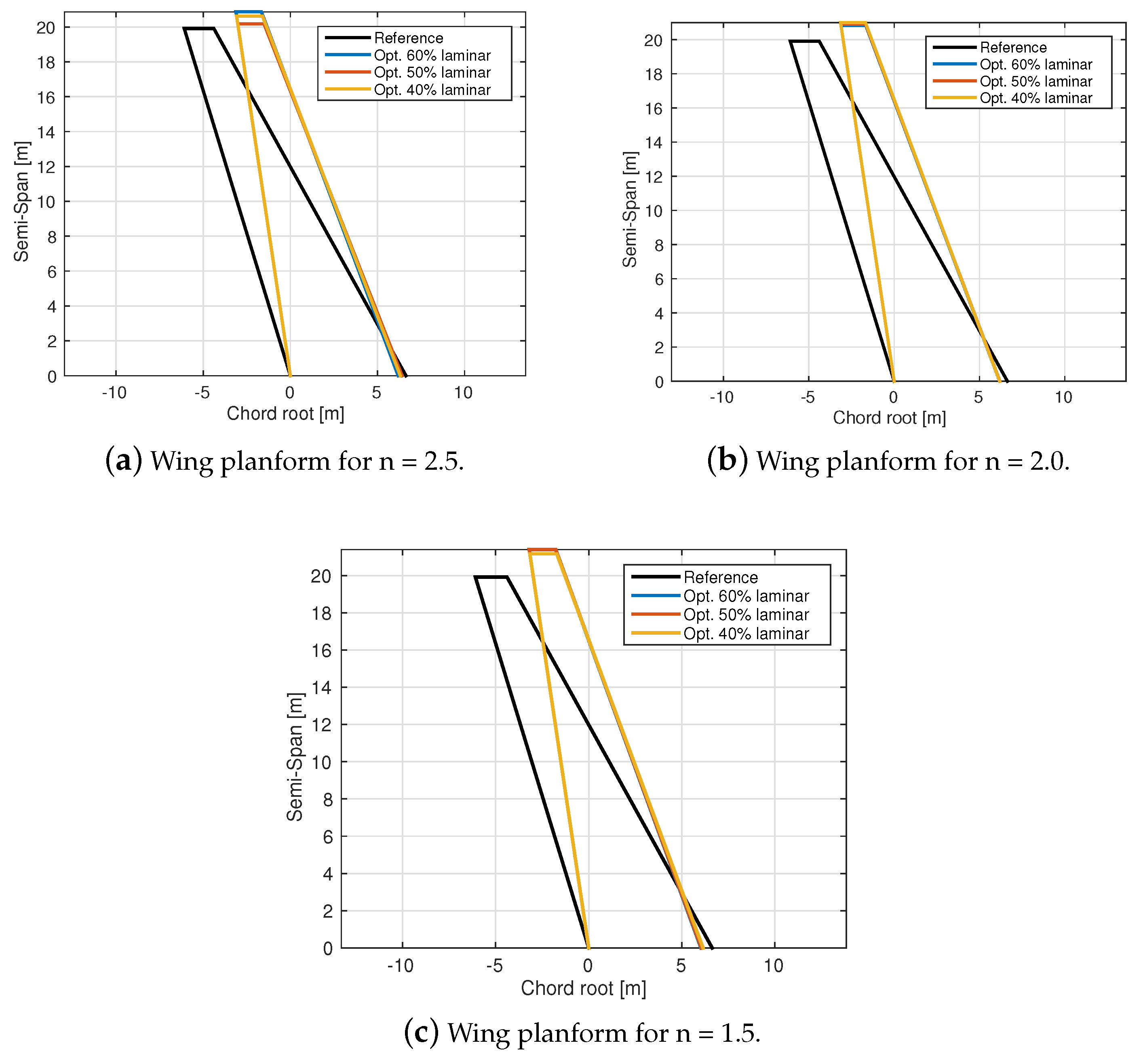
The findings studied in Figure 11 and Figure 12 prove the influence of the design parameters on the aileron constraint and structural weight and the importance of a tradeoff to properly assess the optimum. The influence of wing laminarisation in fuel reduction, at different maximum load factors, can be visualised in Figure 13. In particular, maximum reduction is obtained for the higher use of the technologies, meaning a maximum load factor of 1.5 and 60% laminar flow. In fact, the reduction of for the forward-swept wing case is 5.6%, and the backward-swept configuration presents a reduction of up to 9.8%. Figure 14 presents the optimised wing planform for a different maximum load factor and portion of laminar flow for the forward-swept wing configuration. All cases present the increment of span and aspect ratio to limit the induced drag generated, and minimal variations are obtained between different laminar conditions.
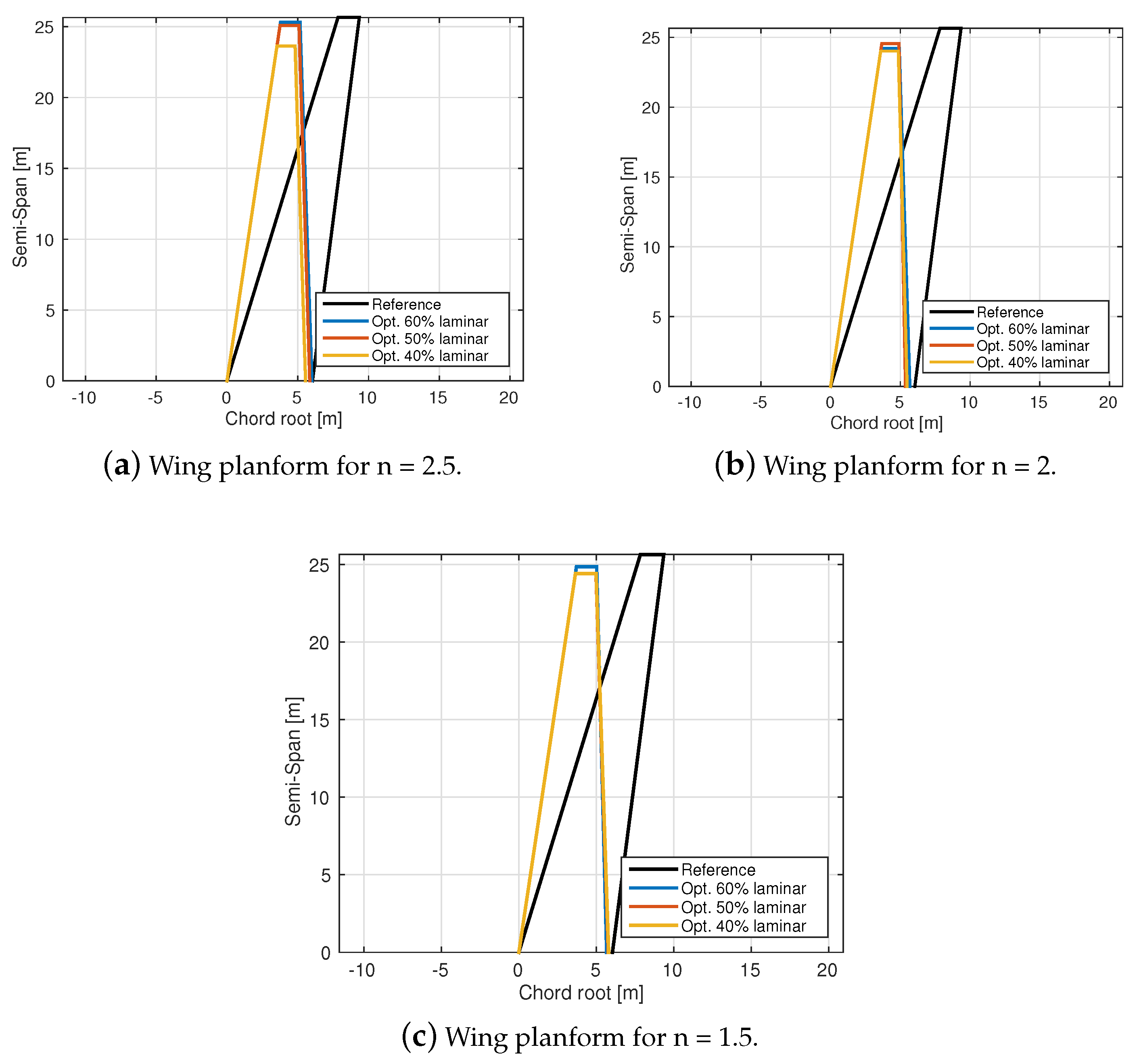
For the backward-swept case shown in Figure 15, an analogous result is reached for the sweep, with its reduction, while the span is lowered. Nevertheless, the aspect ratio is incremented acting on chord root and taper ratio.
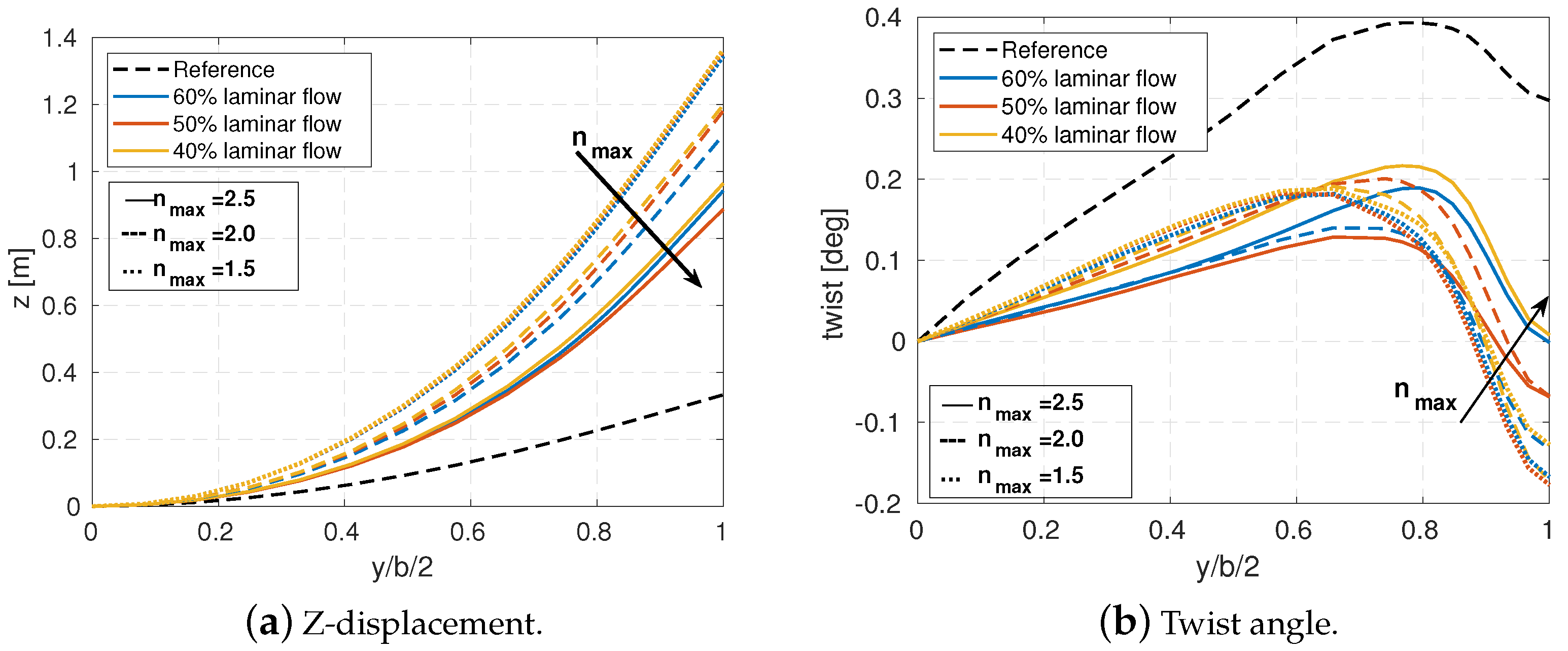
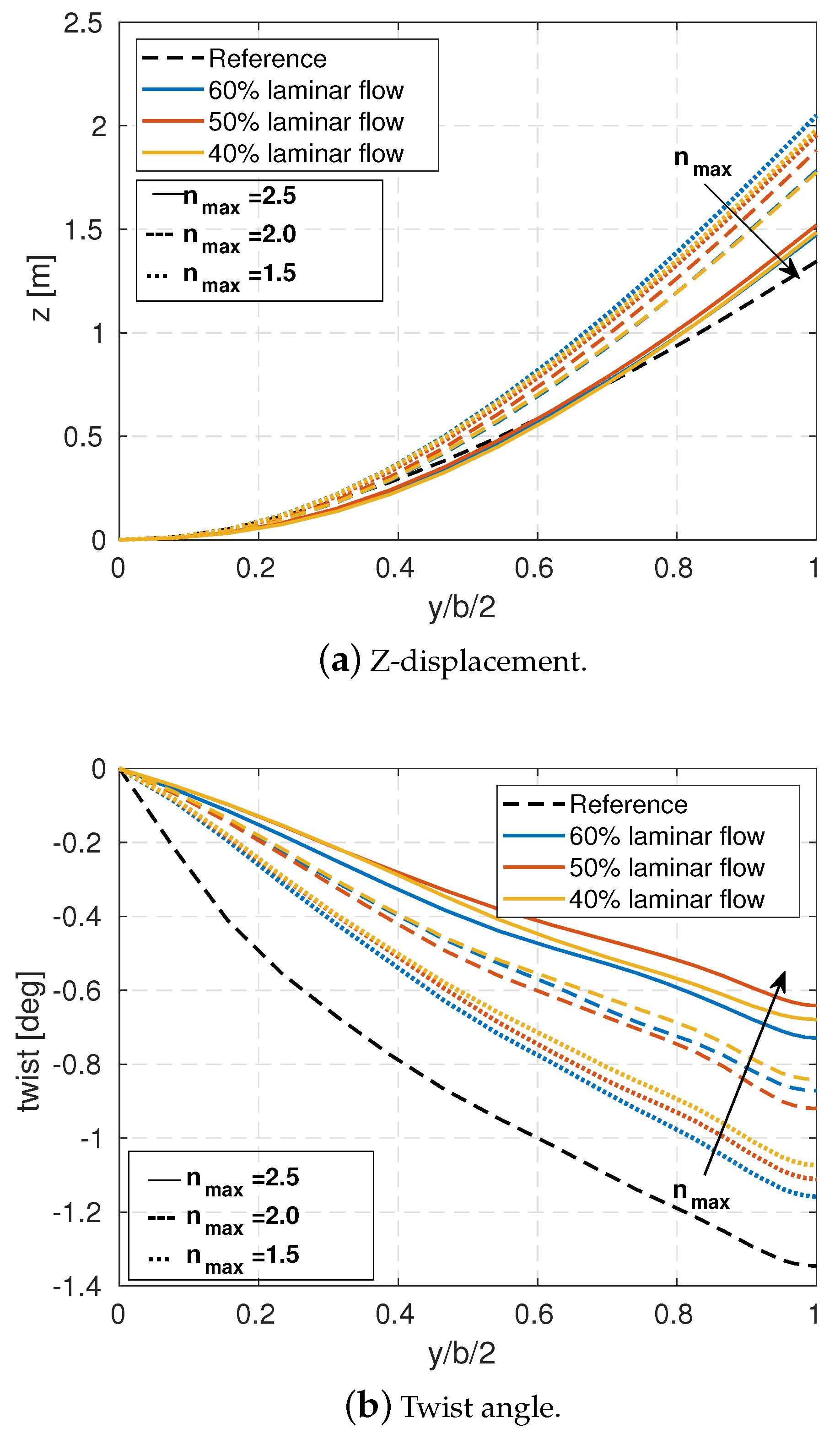
The aeroelastic effect on the wing can be visualised in Figure 16 for the forward-swept configuration. Compared with the reference wing, designed with low fidelity for a and then aeroelastically optimised, the aerostructural optimisations result in a more flexible wing. The reduction of maximum load factor causes an increment of the Z-displacement (bending) (Figure 16a). The wing twist is reduced in Figure 16b, especially at the wing tip, and the optimiser is reducing the twist considering that for this configuration roll constraint is easily satisfied; hence the wing weight can be accordingly reduced, changing the distribution of thickness of the panels and finally changing the effect on twist.
For the backward-swept configuration, a similar aeroelastic effect is achieved, as seen in Figure 17, for the bending deformation. Figure 17a shows the increment of tip displacement and wing twist absolute angle (Figure 17b), consequently presenting higher wing flexibility with the reduction of . This means that the use of the technology able to reduce the loads sustained by the wing may be beneficial for aeroelastic deformation; in fact, the backward-swept wing aircraft presents less roll capability with respect to the forward configuration, with the consequence of a wing weight increase for the high aspect-ratio wing that is compensated thanks to a lower maximum load factor. The higher flexibility of the wing needs to be assessed in terms of roll moment, and the constraint is still satisfied because the potential increment of wing weight is compensated by the lower maximum load factor and in general by the optimised configuration.
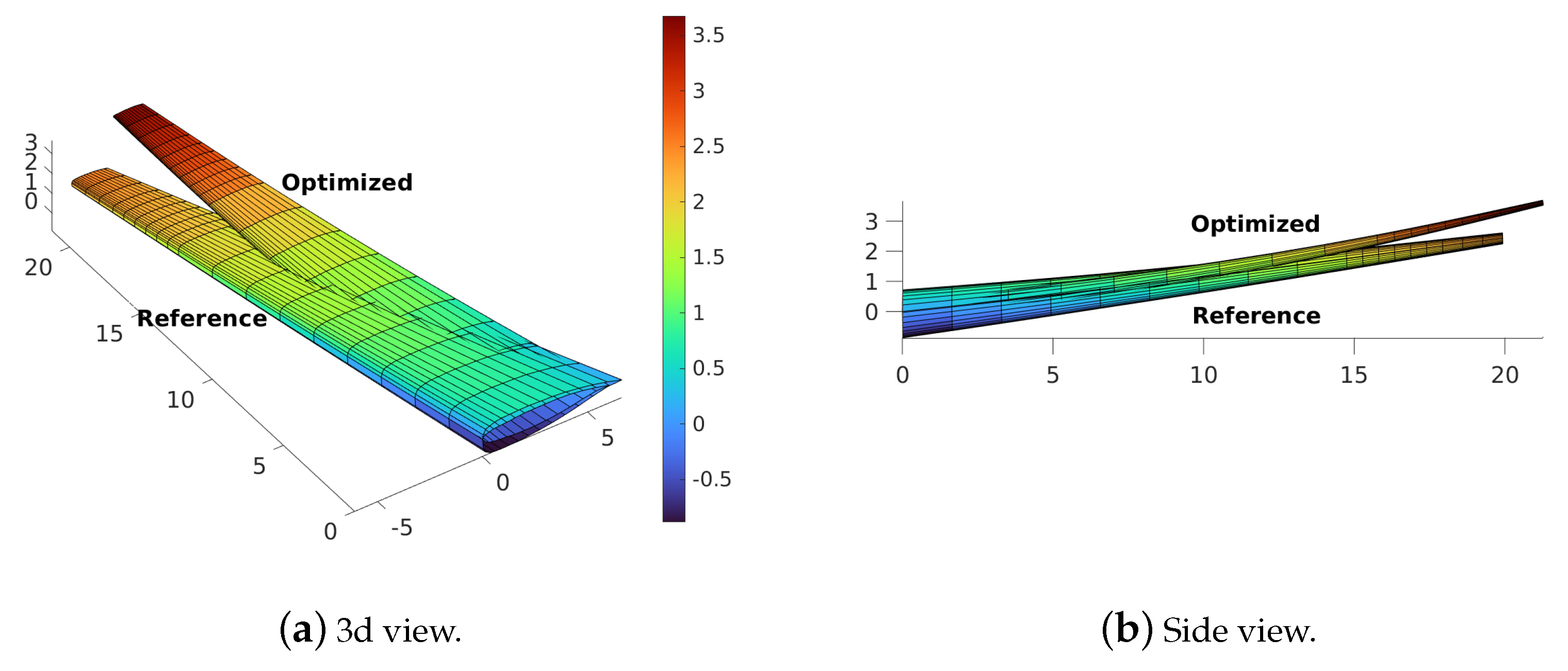
The deformed forward-swept wing configuration, optimised for =1.5, compared to the reference can be visualised in a 3d and a side view in Figure 18.
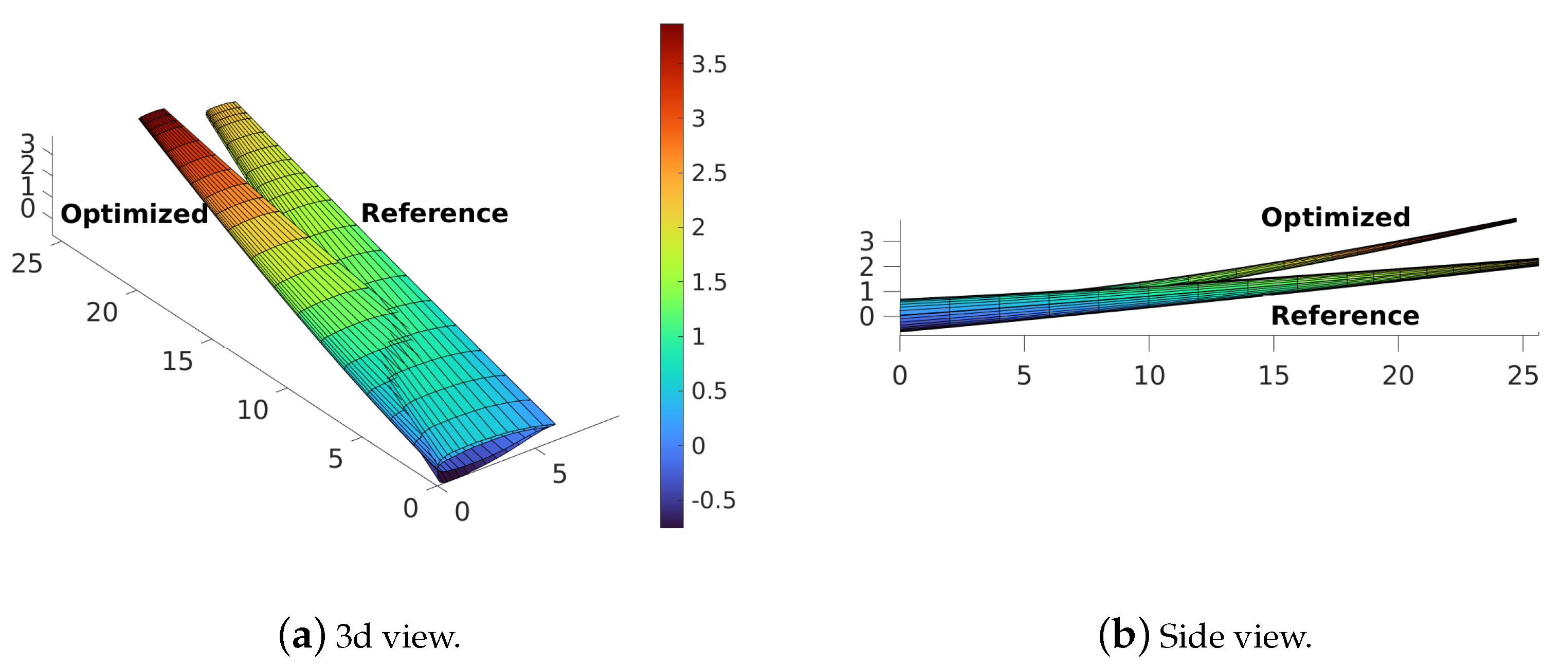
Similarly, the backward-swept case can be visualised in Figure 19.
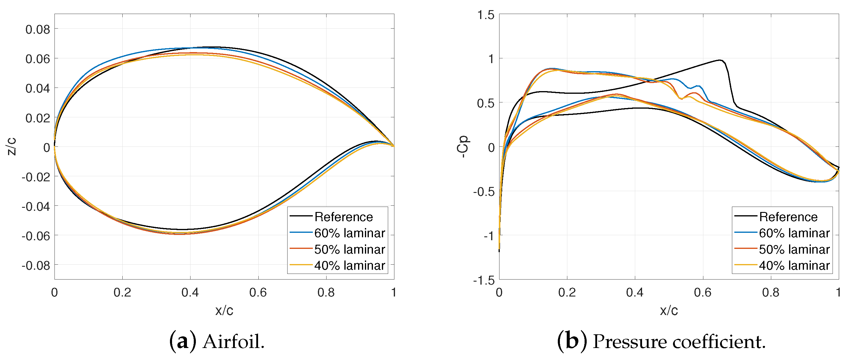
In Figure 20, an example of a wing section for the backward-swept wing aircraft, optimised for a maximum load factor of 1.5 at different portions of laminar flow, shows the capability of the FEMWET optimisation framework to minimise wave drag, even though it has a lower leading edge sweep angle with respect to the reference, weakening the shockwaves. The new optimised airfoil shapes (Figure 20a) reduce the impact of shockwaves, weakening them, as shown in the pressure coefficient distribution (Figure 20b). In fact, the methodology presented in this research is characterised by an interaction between the structures and the aerodynamics, and the interaction needs to be properly assessed in order to reduce ; one way to do this may be the increment of by lowering the wave drag connected to shocks for transient regime. Considering the aerodynamics limitations explained in Section 3.2, a parallel study will follow, able to properly optimise the airfoil acting on the boundary layer equations simulating the boundary layer suction.
6. Conclusions
This research presents an aerostructural gradient-based optimisation framework, characterised by the use of a coupled-adjoint method, automatic differentiation (AD), and chain rule of differentiation to compute derivatives necessary for the gradient. The FEMWET tool integrates a quasi-three-dimensional aerodynamic analysis with a structural study.
A midfidelity optimisation framework is developed to take into account active flow control and different load cases. The former is implemented through the application of drag penalty coefficients applied on the full turbulent airfoil, the latter considering different maximum load factors for the pull-up manoeuvre. In addition, the use of novel materials and structures is accounted for by a predicted reduction of the wing weight. In total, three different aeroelastic optimisations are conducted, to minimise wing weight, thereby varying thicknesses of the wingbox panels. Three different maximum load factors are considered during the pull-up maneuver: 2.5, 2.0, and 1.5. These represent a preliminary sizing from which all the weight quantities are updated and are a necessary step to start the complete aerostructural optimisation. A different laminar portion of flow is studied: 60%, 50%, and 40%. Eighteen aerostructural optimisations are performed for fuel weight minimisation, varying wingbox structure, airfoil shape and wing geometry.
The research is applied to the SE2A forward- and backward-swept wing midrange aircraft. The highest benefits are achieved considering the maximum application of wing laminarisation and minimum load factor: 5.6% and 9.8% of fuel weight is reduced for the two configurations. Hence, the application of novel technologies results advantageous for future transport aircraft design for sustainable aviation.
The forward-swept configuration may be sensitive to the aeroelastic stability effect resulting in a weight increment, whereas the backward configuration presents higher weight variation due to roll constraints. In fact, the backward-swept wing configuration presents higher sensitivity to the aileron constraint. This constraint plays a more active role limiting the optimisation results. No dynamic stability effects are studied, leaving them to higher-fidelity analysis.
Sensitivity studies performed for different conditions, obtained through aeroelastic optimisations, show that augmentation of the maximum thickness-to-chord ratio lowers the wing weight for both wing configurations. On the contrary, an increment of the absolute sweep angle makes the wing weight higher. Aileron effectiveness increases with the absolute leading edge sweep angle, whereas the opposite trend occurs with the augmentation of a maximum thickness-to-chord ratio. In fact, for the forward-swept wing, its increment reduces the aileron effectiveness whereas the backward-swept wing is incrementing. Optimised wings present more flexibility, showing higher tip displacement and different behaviour on the wing twist due to the different sweep configuration of the two cases studied.
The present study shows the development and the application of a midfidelity optimisation framework, with novel technologies for nonconventional aircraft and its possible limitations. For these reasons, further research will present a new approach with tools for boundary-layer solvers and linear stability analysis. These will present a higher level of fidelity for laminar flow control analysis but make the framework be gradient-free because of the possible convergence issues. In this case, the higher-fidelity aerodynamic level will be paid with an increment of computational time.
Author Contributions
Conceptualization, V.M. and A.E.; methodology, V.M. and A.E.; software, V.M. and A.E.; validation, V.M. and A.E.; formal analysis, V.M.; investigation, V.M.; resources, A.E.; data curation, A.E.; writing—original draft preparation, V.M.; writing—review and editing, A.E.; visualization, V.M.; supervision, A.E.; project administration, A.E.; funding acquisition, A.E. All authors have read and agreed to the published version of the manuscript.
Funding
This research was funded by the Deutsche Forschungsgemeinschaft (DFG, German Research Foundation) under Germany’s Excellence Strategy-EXC 2163/1-Sustainable and Energy Efficient Aviation-Project-ID 390881007.
Data Availability Statement
The data presented in this study was generated using the Matlab based software FEMWET. Final data presented in this study are available on request from the corresponding author.
Acknowledgments
We would like to acknowledge the funding by the Deutsche Forschungsgemeinschaft (DFG, German Research Foundation) under Germany’s Excellence Strategy-EXC 2163/1-Sustainable and Energy Efficient Aviation—Project-ID 390881007.
Conflicts of Interest
The authors declare no conflict of interest.
Abbreviations
The following abbreviations are used in this manuscript:
| wing sweep | |
| aileron effectiveness | |
| density | |
| aspect ratio | |
| boundary layer suction | |
| b | span |
| c | chord |
| chord*lift coefficient | |
| pitching moment coefficient | |
| drag coefficient | |
| friction drag coefficient | |
| form drag coefficient (pressure-wave drag) | |
| wave drag coefficient | |
| induced drag coefficient | |
| sectional lift coefficient | |
| wing lift coefficient | |
| pressure coefficient | |
| g | gravitational acceleration |
| H | altitude |
| HLFC | hybrid laminar flow control |
| J | fitness function |
| friction drag correction factor | |
| form drag correction factor | |
| roll moment due to an aileron deflection | |
| lift-to-drag ratio | |
| LFC | laminar flow control |
| M | mach number |
| MDO | multidiscplinary design optimisation |
| MLW | maximum landing weight |
| MTOW | maximum take-off weight |
| m | mass |
| n | load factor |
| NLF | natural laminar flow |
| Reynolds number | |
| S | Surface |
| T | wingbox panels thickness |
| thrust-to-weight ratio | |
| thickness-to-chord ratio | |
| V | volume |
| W | weight |
| wing loading | |
| X | optimisation design vector |
| Subscripts | |
| design | |
| f | fuel |
| leading-edge | |
| r | root |
| s | surrogate |
| t | tip |
| take-off | |
| w | wing |
References
- European Commission. Flightpath 2050: Europe’s Vision for Aviation: Advisory Council for Aeronautics Research in Europe; European Commission: Luxembourg, 2011.
- Horst, P.; Elham, A.; Radespiel, R. Reduction of Aircraft Drag, Loads and Mass for Energy Transition in Aeronautics; Deutsche Gesellschaft für Luft- und Raumfahrt - Lilienthal-Oberth e.V.: Bonn, Germany, 2021. [Google Scholar] [CrossRef]
- Gröhlich, M.; Böswald, M.; Winter, R. An Iterative Eigenvalue Solver for Systems with Frequency Dependent Material Properties; DAGA: Hannover, Germany, 2020; pp. 900–903. [Google Scholar]
- Dähne, S.; Hühne, C. Gradient based structural optimization of a stringer stiffened composite wing box with variable stringer orientation. In Advances in Structural and Multidisciplinary Optimization; Springer: Cham, Switzerland, 2018; pp. 814–826. [Google Scholar] [CrossRef]
- Wunderlich, T.; Dähne, S.; Reimer, L.; Schuster, A.; Brodersen, O. Global aero-structural design optimization of more flexible wings for commercial aircraft. In Proceedings of the AIAA AVIATION 2020 FORUM, Virtual Event, 15–19 June 2020; Volume 33, pp. 1–18. [Google Scholar] [CrossRef]
- Rossow, C.; Geyr, H.; Hepperle, M. The 1 g-Wing, Visionary Concept or Naive Solution? DLR-IB-AS-BS-2016-121; DLR-Interner Bericht: Braunschweig, Germany, 2016. [Google Scholar]
- Liu, X.; Sun, Q. Gust load alleviation with robust control for a flexible wing. Shock Vib. 2016, 2016, 1060574. [Google Scholar] [CrossRef] [Green Version]
- Bi, Y.; Xie, C.; An, C.; Yang, C. Gust load alleviation wind tunnel tests of a large-aspect-ratio flexible wing with piezoelectric control. Chin. J. Aeronaut. 2017, 30, 292–309. [Google Scholar] [CrossRef]
- Khalil, K.; Asaro, S.; Bauknecht, A. Active flow control devices for wing load alleviation. In Proceedings of the AIAA Aviation 2020 Forum, Virtual, 15–19 June 2020; pp. 1–22. [Google Scholar]
- Braslow, A. A History of Suction-Type Laminar Flow Control with Emphasis on Flight Research; Monographs in Aerospace History Number 13; NASA: Washington, DC, USA, 1999.
- Krishnan, K.; Bertram, O.; Seibel, O. Review of hybrid laminar flow control systems. Prog. Aerosp. Sci. 2017, 93, 24–52. [Google Scholar] [CrossRef]
- Spalart, P.R.; McLean, J.D. Drag reduction: Enticing turbulence, and then an industry. Philos. Trans. R. Soc. A Math. Phys. Eng. Sci. 2011, 369, 1556–1569. [Google Scholar] [CrossRef] [PubMed] [Green Version]
- Beck, N.; Landa, T.; Seitz, A.; Boermans, L.; Liu, Y.; Radespiel, R. Drag reduction by laminar flow control. Energies 2018, 11, 252. [Google Scholar] [CrossRef] [Green Version]
- Sudhi, A.; Elham, A.; Badrya, C. Coupled boundary layer suction and airfoil shape optimization for hlfc application. AIAA J. 2021, 59, 5158–5173. [Google Scholar] [CrossRef]
- Mosca, V.; Karpuk, S.; Sudhi, A.; Badrya, C.; Elham, A. Multidisciplinary design optimisation of a fully electric regional aircraft wing with active flow control technology. Aeronaut. J. 2021, 126, 730–754. [Google Scholar] [CrossRef]
- Sudhi, A.; Radespiel, R.; Badrya, C. Design of transonic swept wing for hlfc application. In Proceedings of the AIAA AVIATION 2021 Forum, Virtual Event, 2–6 August 2021. [Google Scholar] [CrossRef]
- Liem, R.P.; Mader, C.A.; Lee, E.; Martins, J.R.R.A. Aerostructural design optimization of a 100-passenger regional jet with surrogate-based mission analysis. In Proceedings of the 2013 Aviation Technology, Integration, and Operations Conference, Los Angeles, CA, USA, 12–14 August 2013. [Google Scholar] [CrossRef] [Green Version]
- Karpuk, S.; Mosca, V.; Liu, C.; Elham, A. Development of a Multi-fidelity Design, Analysis, and Optimization Environment for Future Transport Aircraft. In Proceedings of the AIAA SCITECH 2022 Forum, San Diego, CA, USA, 3–7 January 2022. [Google Scholar]
- Kenway, G.K.W.; Kennedy, G.J.; Martins, J.R.R.A. Scalable parallel approach for high-fidelity steady-state aeroelastic analysis and adjoint derivative computations. AIAA J. 2014, 52, 935–951. [Google Scholar] [CrossRef] [Green Version]
- Certification Specifications and Acceptable Means of Compliance for Large Aeroplanes CS-25. June 2020. Available online: https://perma.cc/9K76-KJPW (accessed on 28 April 2022).
- Karpuk, S.; Elham, A. Conceptual Design Trade Study for an Energy-Efficient Mid-Range Aircraft with Novel Technologies. In Proceedings of the AIAA Scitech 2021 Forum, Virtual Event, 11–15, 19–21 January 2021. [Google Scholar] [CrossRef]
- Hahn, D.; Haupt, M. Exploration of the effect of wing component post-buckling on bending-twist coupling for nonlinear wing twist. CEAS Aeronaut. J. 2022, 13, 663–676. [Google Scholar] [CrossRef]
- Handojo, V.; Himisch, J.; Bramsiepe, K.; Krüger, W.R.; Tichy, L. Potential Estimation of Load Alleviation and Future Technologies in Reducing Aircraft Structural Mass. Aerospace 2022, 9, 412. [Google Scholar] [CrossRef]
- Karpuk, S.; Radespiel, R.; Elham, A. Assessment of Future Airframe and Propulsion Technologies on Sustainability of Next-Generation Mid-Range Aircraft. Aerospace 2022, 9, 279. [Google Scholar] [CrossRef]
- Elham, A.; van Tooren, M.J. Coupled adjoint aerostructural wing optimization using quasi-three-dimensional aerodynamic analysis. Struct. Multidiscip. Optim. 2016, 54, 889–906. [Google Scholar] [CrossRef] [Green Version]
- Dorbath, F.; Nagel, B.; Gollnick, V. Comparison of beam and shell theory for mass estimation in preliminary wing design. In Proceedings of the 2nd Aircraft Structural Design Conference, London, UK, 26–28 October 2010. [Google Scholar]
- Elham, A.; La Rocca, G.; Van Tooren, M.J. Development and implementation of an advanced, design-sensitive method for wing weight estimation. Aerosp. Sci. Technol. 2013, 29, 100–113. [Google Scholar] [CrossRef]
- Elham, A.; Van Tooren, M.J. Tool for preliminary structural sizing, weight estimation, and aeroelastic optimization of lifting surfaces. Proc. Inst. Mech. Eng. Part G J. Aerosp. Eng. 2016, 230, 280–295. [Google Scholar] [CrossRef]
- Niu, M. Airframe Stress Analysis and Sizing; Conmilit Press Ltd.: Hong Kong, China, 2021. [Google Scholar]
- Kennedy, G.; Martins, J. A parallel aerostructural optimization framework for aircraft design studies. Struct Multidisc Optim 2014, 50, 1079–1101. [Google Scholar] [CrossRef]
- Mariens, J.; Elham, A.; Van Tooren, M.J. Quasi-three-dimensional aerodynamic solver for multidisciplinary design optimization of lifting surfaces. J. Aircr. 2014, 51, 547–558. [Google Scholar] [CrossRef]
- Katz, J.; Plotkin, A. Low Speed Aerodynamics; Cambridge University Press: Cambridge, UK, 2001. [Google Scholar]
- Flandro, G.A.; McMahon, H.M.; Roach, R.L. Basic Aerodynamics: Incompressible Flow; Cambridge University Press: New York, NY, USA, 2012. [Google Scholar]
- Meheut, M.; Bailly, D. Drag-breakdown methods from wake measurements. AIAA J. 2008, 46, 847–862. [Google Scholar] [CrossRef]
- Drela, M. Simultaneous Optimization of the Airframe, Powerplant, and Operation of Transport Aircraft. In Proceedings of the 2nd Aircraft Structural Design Conference, London, UK, 26–28 October 2010. [Google Scholar]
- Drela, M. N+3 Aircraft Concept Designs and Trade Studies, vol. 2 (Appendices): Design Methodologies for Aerodynamics, Structures, Weight, and Thermodynamic Cycles (Appendix A: TASOPT Transport Aircraft System OPTimization). In Proceedings of the 2nd Aircraft Structural Design Conference, London, UK, 26–28 October 2010. [Google Scholar]
- Drela, M. Design and optimization method for multi-element airfoils. In Proceedings of the Aerospace Design Conference, Irvine, CA, USA, 16–19 February 1993; p. 969. [Google Scholar]
- Drela, M.; Giles, M.B. Viscous-inviscid analysis of transonic and low reynolds number airfoils. AIAA J. 1987, 25, 1347–1355. [Google Scholar] [CrossRef]
- Ferreira, C. Implementation of Boundary Layer Suction in Xfoil and Application of Suction Powered by Solar Cells at High Performance Sailplanes. Master’s Thesis, TU Delft, Delft, The Netherlands, 2012. [Google Scholar]
- Bisplinghoff, R.; Holt, A.; Halfman, R.L. Aeroelasticity; Dover Publications, Inc.: Mineola, NY, USA, 1996. [Google Scholar]
- Wright, J.R.; Cooper, J.E. Introduction to Aircraft Aeroelasticity and Loads, 2nd ed.; John Wiley & Sons, Ltd.: Hoboken, NJ, USA, 2015. [Google Scholar]
- Bindolino, G.; Mantegazza, P.; Masarati, P. Aeroelasticità Applicata. Ph.D. Thesis, Dipartimento di Ingegneria Aerospaziale, Politecnico di Milano via La Masa, Milano, Italy, 1999. Volume 34. p. 20156. [Google Scholar]
- Seitz, A.; Hübner, A.; Risse, K. The dlr tulam project: Design of a short and medium range transport aircraft with forward swept nlf wing. CEAS Aeronaut. J. 2020, 11, 449–459. [Google Scholar] [CrossRef] [Green Version]
- Xue, R.; Ye, Z.; Ye, K. Active aeroelastic wing application on a forward swept wing configuration. Eng. Appl. Comput. Fluid Mech. 2019, 13, 1063–1079. [Google Scholar] [CrossRef] [Green Version]
- Sadraey, M. Aircraft Design A Systems Engineering Approach; John Wiley & Sons, Ltd.: Hoboken, NJ, USA, 2012. [Google Scholar]
- Bindolino, G.; Ghiringhelli, G.; Ricci, S.; Terraneo, M. Multilevel structural optimization for preliminary wingbox weight estimation. J. Aircr. 2010, 47, 475–489. [Google Scholar] [CrossRef]
- MIL-F-8785C; Military Specification: Flying Qualities of Piloted Airplanes. Department of Defense: Washington, DC, USA, 1980.
- Roskam, J. Airplane Design, Part, I: Preliminary Sizing of Airplanes; DARcorporation: Ottawa, KS, USA, 2017. [Google Scholar]
- Van der Wees, A.; van Muijden, J.J.; van der Vooren, J. A fast and robust viscous-inviscid interaction solver for transonic flow about wing/body configurations on the basis of full potential theory. In Proceedings of the 23rd Fluid Dynamics, Plasmadynamics, and Lasers Conference, Orlando, FL, USA, 6–9 July 1993; pp. 1993–3026. [Google Scholar]
- Van der Vooren, J.; van der Wees, A.J. Inviscid drag prediction for transonic transport wings using a full-potential method. J. Aircr. 1991, 28, 869–875. [Google Scholar] [CrossRef]
- Obert, E. Aerodynamic Design of Transport Aircraft; IOS Press: Amsterdam, The Netherlands, 2009. [Google Scholar]
- Schrauf, G. Coco—A Program to Compute Velocity and Temperature Profiles for Local and Non Local Stability Analysis of Compressible, Conical Boundary Layers with Suction; ZARM Technik Report; ZARM Technik AG: Bremen, Germany, 1998. [Google Scholar]
- Schrauf, G. Lilo 2.1 User’s Guide and Tutorial; GSSC Technical Report 6; ZARM Technik AG: Bremen, Germany, 2006. [Google Scholar]
- Krumbein, A. Transition modeling in flower—Transition prescription and prediction. In MEGAFLOW—Numerical Flow Simulation for Aircraft Design; Kroll, N., Fassbender, J.K., Eds.; Springer: Berlin/Heidelberg, Germany, 2005; pp. 45–62. [Google Scholar]
Figure 1.
Configuration layouts for the midrange aircraft [21].
Figure 1.
Configuration layouts for the midrange aircraft [21].

Figure 2.
Prediction and confidence interval.

Figure 3.
Friction drag penalty model.

Figure 4.
Form drag penalty model.

Figure 5.
Static aeroelastic problem.

Figure 6.
Scheme for minimum roll moment derivative, reversing aileron design from [45].
Figure 6.
Scheme for minimum roll moment derivative, reversing aileron design from [45].

Figure 7.
Sensitivity comparison for different design variables.

Figure 8.
TuLam wing lift distribution from [43] and using FEMWET.
Figure 8.
TuLam wing lift distribution from [43] and using FEMWET.

Figure 9.
MDO problem.

Figure 10.
variation for backward-swept configuration.

Figure 11.
Influence of t/c and on and , for a backward-swept wing.

Figure 12.
Influence of t/c and on and , for a forward-swept wing.

Figure 13.
SE2A midrange reduction.

Figure 14.
Forward-swept wing geometry at different load factor and portion of laminar flow.

Figure 15.
Backward-swept wing geometry at different load factor and portion of laminar flow.

Figure 16.
Forward-swept aeroelastic deformation.

Figure 17.
Backward-swept aeroelastic deformation.

Figure 18.
Forward-swept wing aircraft aeroelastic deformation at cruise.

Figure 19.
Backward-wing aircraft aeroelastic deformation at cruise.

Figure 20.
Backward-swept wing section for the optimised configuration with = 1.5.


Table 1.
SE2A Midrange aircraft top-level requirements (adapted from [21]).
Table 1.
SE2A Midrange aircraft top-level requirements (adapted from [21]).
| Parameter | Value | Units |
|---|---|---|
| Design range for maximum payload | 3981 | km |
| Maximum number of passengers | 186 | |
| Maximum payload weight | 19,625 | kg |
| Cruise Mach number | 0.78 | |
| Climb rate at top-of-climb | 3.00 | m/s |
| Sustained turn angle at the cruise altitude | 15 | deg |
| Range with maximum payload | 3982 | km |
| Take-off field length at MTOW | 2000 | m |
| Landing field length at MLW | 1530 | m |
Table 2.
SE2A Midrange aircraft reference data.
| Fwd-Swept | Bwd-Swept | ||
|---|---|---|---|
| Parameter | Value | Value | Units |
| Span | 39.83 | 51.30 | m |
| Chord root | 6.63 | 6.04 | m |
| Taper ratio | 0.26 | 0.25 | |
| Cruise Mach number | 0.78 | 0.78 | |
| Dihedral angle | 6 | 4 | deg |
| Sweep angle (leading edge) | 17 | 17 | deg |
| Twist angle (root) | 0 | 0 | deg |
| Twist angle (tip) | 0 | 0 | deg |
| Airfoil | DLR F15 | DLR F15 | |
| Root thickness | 13.3% | 12% | |
| Tip thickness | 10% | 10% |
Table 3.
Drag penalty coefficients.
| % Laminar Flow | ||
|---|---|---|
| 60% | 0.56 | 0.27 |
| 50% | 0.64 | 0.40 |
| 40% | 0.72 | 0.52 |
Table 4.
Drag comparison for different test cases.
| Case | Type | Value [] | Value in FEMWET [] |
|---|---|---|---|
| HLFC Airfoil [16] | Profile drag | 33.2 | 34.8 |
| TuLam [43] | Viscous drag | 44.4 | 43.1 |
Table 5.
SE2A midrange load cases.
| Load Case | Type | Aircraft Weight | H [m] | M | n [g] |
|---|---|---|---|---|---|
| 1 | pull-up | MTOW | 7500 | 0.89 | |
| 2 | pull-up | MTOW | 0 | 0.58 | |
| 3 | push-over | MTOW | 7500 | 0.89 | -1 |
| 4 | gust | ZFW | 7500 | 0.89 | 1.3 |
| 5 | roll | W | 4000 | 0.82 | 1 |
| 6 | cruise | W | 10,600 | 0.78 | 1 |
Table 6.
SE2A midrange forward-swept wing optimisation results.
| MTOW [kg] | [kg] | [kg] | |||||
|---|---|---|---|---|---|---|---|
| Ref. = 2 | 60% lam. | 69,823 | 8952 | 9559 | 0.01823 | 0.00776 | 20.60 |
| 2.5 | 60% | 67,230 | 8524 | 7394 | 0.01805 | 0.00716 | 20.85 |
| 50% | 67,457 | 8725 | 7420 | 0.01877 | 0.00791 | 20.02 | |
| 40% | 67,706 | 8860 | 7535 | 0.01925 | 0.00843 | 19.51 | |
| 2.0 | 60% | 66,869 | 8484 | 7072 | 0.01803 | 0.00709 | 20.85 |
| 50% | 67,287 | 8659 | 7317 | 0.01856 | 0.00769 | 20.24 | |
| 40% | 67,458 | 8809 | 7337 | 0.01910 | 0.00826 | 19.64 | |
| 1.5 | 60% | 66,967 | 8450 | 7205 | 0.01783 | 0.00692 | 21.07 |
| 50% | 67,288 | 8633 | 7343 | 0.01844 | 0.00758 | 20.35 | |
| 40% | 67,531 | 8803 | 7416 | 0.01925 | 0.00834 | 19.64 |
Table 7.
SE2A midrange backward-swept wing optimisation results.
| MTOW [kg] | [kg] | [kg] | |||||
|---|---|---|---|---|---|---|---|
| Ref. =2 | 60% lam. | 77,496 | 9853 | 15,562 | 0.01539 | 0.00650 | 23.23 |
| 2.5 | 60% | 71,140 | 9080 | 9979 | 0.01523 | 0.00603 | 22.30 |
| 50% | 71,561 | 9313 | 10,167 | 0.01649 | 0.00696 | 21.45 | |
| 40% | 70,192 | 9359 | 8752 | 0.01888 | 0.00822 | 20.49 | |
| 2.0 | 60% | 70,133 | 8965 | 9087 | 0.01655 | 0.00639 | 22.34 |
| 50% | 70,228 | 9132 | 9015 | 0.01794 | 0.00733 | 21.54 | |
| 40% | 70,260 | 9343 | 8836 | 0.01873 | 0.00812 | 20.60 | |
| 1.5 | 60% | 69,340 | 8890 | 8369 | 0.01610 | 0.00617 | 22.19 |
| 50% | 69,317 | 9113 | 8123 | 0.01690 | 0.00697 | 21.09 | |
| 40% | 69,662 | 9324 | 8256 | 0.01751 | 0.00762 | 20.34 |
Publisher’s Note: MDPI stays neutral with regard to jurisdictional claims in published maps and institutional affiliations. |
© 2022 by the authors. Licensee MDPI, Basel, Switzerland. This article is an open access article distributed under the terms and conditions of the Creative Commons Attribution (CC BY) license (https://creativecommons.org/licenses/by/4.0/).
Share and Cite
MDPI and ACS Style
Mosca, V.; Elham, A. Investigations on the Potentials of Novel Technologies for Aircraft Fuel Burn Reduction through Aerostructural Optimisation. Aerospace 2022, 9, 744. https://doi.org/10.3390/aerospace9120744
AMA Style
Mosca V, Elham A. Investigations on the Potentials of Novel Technologies for Aircraft Fuel Burn Reduction through Aerostructural Optimisation. Aerospace. 2022; 9(12):744. https://doi.org/10.3390/aerospace9120744
Chicago/Turabian StyleMosca, Valerio, and Ali Elham. 2022. "Investigations on the Potentials of Novel Technologies for Aircraft Fuel Burn Reduction through Aerostructural Optimisation" Aerospace 9, no. 12: 744. https://doi.org/10.3390/aerospace9120744
Note that from the first issue of 2016, this journal uses article numbers instead of page numbers. See further details here.