
Thrust Control of Lab-Scale Hybrid Rocket Motor with Wax-Aluminum Fuel and Air as Oxidizer

Department of Aerospace Engineering, Indian Institute of Technology Madras, Chennai 600036, India
*
Author to whom correspondence should be addressed.
Aerospace 2022, 9(9), 474; https://doi.org/10.3390/aerospace9090474
Submission received: 22 July 2022
/
Revised: 14 August 2022
/
Accepted: 19 August 2022
/
Published: 26 August 2022
(This article belongs to the Special Issue Aerospace Combustion Engineering)
Abstract
:This article explores the throttling aspect of the hybrid rocket motor through experiments using a lab-scale motor. The lab-scale motor utilizes a wax-Al based fuel and compressed air as the oxidizer. The oxidizer flow rate was modulated using a PID controller to study the closed-loop thrust control performance of the motor. Numerical simulations and cold flow tests were carried out to identify the suitable gains for the PID control algorithm. Pressure feedback was used in the control algorithm to obtain the closed-loop thrust control. The resultant closed-loop system followed the reference pressure accurately during the step input response test of the system. The maximum error in the observed chamber pressure was % for a reference pressure of bar, which corresponds to a reference thrust of N. The response of the system for a ramp input, with linear thrust variation from N to N, showed that the measured thrust followed the desired ramp profile with a root-mean-square error of N. A ramp-down test with the same thrust range produced a root-mean-square error of N.
1. Introduction
Hybrid rocket motors are throttleable rocket systems that conventionally use a solid fuel and liquid/gaseous oxidizer. At present, the other main rocket motor systems, especially solid motor and liquid rocket engines, are recognized as proven technologies and are widely used in various scientific and military applications. The hybrid rocket motor system is not yet regarded as a mature technology and is yet to find large-scale commercial applications. The huge disparity in the development of the different rocket motor technologies occurred during the latter half of the 20th century. The race for dominance and the time crunch fueled the promotion of solid motors and liquid rocket engines. This period of fast-paced development helped these two technologies gain a considerable advantage over hybrid rocket motors, which had a similar timeline but fell short of becoming a matured technology. In this period, the hybrid rocket motor was overlooked because of its inherent limitations such as low regression rate and volumetric efficiency, varying oxidizer-to-fuel (O/F) ratio, among others [1]. With all the disadvantages associated with a hybrid rocket motor, extensive research was needed to prove it as a reliable system.
Currently, the research on the hybrid motor is re-emerging due to its safety features and ease of handling [2,3,4]. The study presented in this article explored the untapped potential of the hybrid rocket motor as a variable thrust rocket motor system. Current day military aircraft are becoming increasingly expensive due to the technologies added into them. Such assets need to be carefully handled and need to be deployed in an efficient manner. Towards this, the development of a vertical take-off and landing (VTOL) system for the military aircraft was initiated. The development of a controllable hybrid rocket motor is the initial milestone towards one way of realizing the VTOL concept. A controllable hybrid rocket motor that is capable of producing large thrusts for a short duration will satisfy the thrust requirement during the VTOL phase. This will help in reducing the aircraft engine size, which otherwise would have been designed for the high thrust requirement of the VTOL phase. Besides this, a throttleable hybrid rocket motor will be a less complex alternative to handle many missions carried out using liquid rockets. Thus, the development of a reliable hybrid rocket motor with thrust control will enhance the commercial value of the hybrid rocket motor system.
At present, many of the disadvantages attributed to hybrid rocket motors are resolved, and extensive studies are conducted to overcome the remaining ones. The study carried out by Karabeyoglu et al. [5] using liquefying fuel —which forms an unstable melt layer—showed an order of magnitude increase in the regression rate in comparison to classical hybrid rocket fuels such as Hydroxyl-terminated polybutadiene (HTPB). Karabeyoglu et al. [5] was able to predict the high regression rate of cryogenic solid fuels using the theory of unstable melt layer formation in liquefying fuels. This liquid layer combustion theory was extended to non-cryogenic fuels such as paraffin wax, polyethylene wax, etc., and was validated using experimental results. Smoot and Price [6] used metal hydride to enhance the burn rate of a non-liquifying hybrid fuel such as butyl rubber. They observed an increase in burn rate when the metal hydride percentage was increased from 50–90%. Strand et al. [7], Chiaverini et al. [8] and Paravan [9] studied the enhancement of fuel regression rate with the addition of aluminum and reported a significant increase when compared to non-metalized fuels. The increase in regression rate is attributed to the increase in radiative heat transfer [8] and the energy released during the metal oxidation (Thomas et al. [10]). Kumar and Ramakrishna [11,12] used bluff body and protrusion in a lab-scale motor to obtain a higher regression rate for paraffin wax fuel grain. The authors also showed that mass flux index (n) could be brought close to when a bluff-body was used, which will help reduce the O/F variation. Chen et al. [13], in their article, gave a comprehensive discussion on some of the emerging technologies to improve the combustion properties of solid fuel in a hybrid rocket motor. The survey discussed about self-disintegration fuel structure (SDFS), high thermal conductivity fuels, etc. The authors found that SDFS is a promising innovation that needs to be studied further.
Studies regarding the throttling of hybrid rocket motor date back to the 1980s [14], but the technology is still not developed to that extent to make it a reliable alternative for its counterpart. At present, there is an increase in the research interest towards the throttling capability of hybrid rockets. Waidmann [14] used aromatic and cyclic amines as the fuels and red fuming nitric acid (RFNA) as the oxidizer for the throttling studies. A secondary injection of N and O was used to improve the thrust modulation performance and efficiency at a lower oxidizer flow rate. Marothiya et al. [15] demonstrated pulsing and restart capability of a hybrid rocket motor using wax-aluminum fuel and HO oxidizer. It is interesting to note that Marothiya et al. [15] did not use a catalytic bed to decompose HO. Austin et al. [16] demonstrated the throttling and restart capabilities of hybrid rocket motor using a 90% HO as oxidiser and polyethylene (PE) as fuel. The authors reported a thrust turn-down ratio of 10:1. A thrust turn-down ratio of 5.32:1 was achieved by Zhao et al. [17] using HO as oxidizer and polyethylene as the solid fuel. The oxidizer flow controller system used in that study had a cavitating venturi with a controllable pintle that varies the throat area of the venturi. Ruffin et al. [18] also used a flow control valve that is based on variable area cavitating venturi for throttling. They demonstrated pre-programmed dynamic throttling with sine wave and rectangular impulse profiles. Ruffin et al. [18] obtained a thrust turn-down ratio of 12.6:1 with the HO and high density polyethylene propellant formulation. In another study, HTPB based fuel and nitrous oxide were used to obtain a deep throttling of 67:1 [19]. In this, Whitmore et al. [19] used an industrial ball valve with a servo motor actuator to control the oxidizer flow rate. Compared to all existing liquid engines and hybrid rocket motors, Whitmore et al.’s [19] is acknowledged as the largest stable thrust turn-down ratio.
All these studies highlighted the throttling capability of a hybrid rocket motor system. The next waypoint towards qualifying a hybrid rocket motor as a throttleable rocket motor system is to develop a closed-loop thrust control. Studies on closed-loop thrust control of hybrid rocket motor are emerging ([20,21,22]) even though they are less in numbers. Whitmore et al. [20] was able to achieve stable thrust control, thus reducing the run-to-run thrust variability of the hybrid rocket motor to ±1.5%. The study used simulations of the closed-loop control system to obtain the PID controller gains for the actual system. Choi et al. [21] obtained thrust control in the margin of ±1 N with a maximum thrust of up to 50 N using gaseous oxygen as oxidizer and Polyethylene and Poly-carbonate as fuels. Paraffin wax (a liquefying fuel) was used by Velthuysen et al. [22] with nitrous oxide to study the closed-loop throttling capability of the hybrid rocket motor. The authors used a PID controller with thrust feedback in conjunction with a feed-forward loop. The feed-forward loop was included to bring down the transient effect of the motor and nonlinearity in the oxidizer flow. They were able to attain throttling within % of the set point thrust. In these studies, thrust control was the main objective, whereas Messineo and Shimada [23] conducted a theoretical study to understand the feasibility to regulate thrust and O/F simultaneously using a feedback controller. They studied the influence of measurement error on the controller using error propagation analysis and found that the altering intensity swirling oxidizer flow type (A-SOFT) engines were found to limit error propagation.
The oxidizer used in the hybrid rocket motor for this study is high-pressure air stored at ambient temperature. In the literature available with regard to using air as an oxidizer for hybrid rocket motor, most of them used enriched air composition that has more oxygen content than normal air. Whitmore and Bulcher [24] successfully demonstrated hybrid rocket combustion using enriched air with 36% of oxygen by volume as an oxidizer for an acrylonitrile butadiene styrene (ABS) fuel. Interestingly, the solid fuel ramjet (SRJ) with port burning configuration also used high-pressure air stored at ambient temperature as the oxidizer for the solid fuels in the primary chamber [25,26].
As discussed earlier, this article is a study towards the development of a controllable hybrid rocket motor in order to realize a novel VTOL mechanism. For a gas turbine engine-based VTOL system, the maximum thrust requirement will be more than the weight of the fully loaded aircraft. This will demand a large and bulkier engine. During the cruise, this engine will be underutilized as the drag to be countered is only a small fraction of the weight. Furthermore, the larger engine size could also increase the profile drag of the aircraft, whereas the hybrid rocket based VTOL system is designed to produce high thrust for a short duration, which is exactly the requirement during a VTOL. The higher density of the solid fuels will ensure a compact thruster that can be mounted in the aircraft. Other than this, a lower air to fuel (A/F) ratio hybrid propellant will be less demanding on the main engine and it will help in decoupling the main engine and VTOL system to some extent. Figure 1 shows a conceptual diagram of the VTOL mechanism.
The development of such a system involves the identification of fuel and oxidizer, implementation of the control algorithm, and the study of the performance of the system for different control inputs. The oxidizer flow rate was controlled using a servo motor-ball valve arrangement developed for this purpose. The propellant identified was characterized first, and after that, it was tested for throttling capabilities. A PID controller was implemented to obtain closed-loop thrust control of the system.
In this study, special emphasis was given to the development of a fuel that can work with high-pressure air stored at ambient temperature as the oxidizer and not enriched air as used in some of the literature. To use a hybrid rocket motor for VTOL application, the high-pressure air from the gas turbine engines (either exiting the turbine or a bleed from the high-pressure or low-pressure compressor) can be used as the oxidizer. To simulate this condition in experiments, the current study used compressed air as the oxidizer. However, unlike the compressed air bled from a gas turbine engine, the compressed air used in the experiments is at ambient temperature making it a demanding task to initiate combustion. The fuel used for the lab-scale motor was a mixture of wax and activated aluminum powder. The addition of aluminum in the fuel will bring down the optimal air to fuel (A/F) ratio, thus reducing the amount of air required to be diverted from the main engine of the aircraft during a VTOL scenario. The microcontroller used in this study is very affordable, yet powerful enough to handle the requirement of the experimental tests. The microcontroller has the capability to work as a standalone module which makes it easier to incorporate it on the VTOL test platform at a later date.
This article covers the development of a controllable lab-scale hybrid rocket motor and is organized into different sections: experimental setup, simulation model, control algorithm, and results and discussion. The section on the experimental setup describes the fuel preparation procedure, the lab-scale motor, the control module, and the experimental procedure. The numerical simulation model used for control algorithm simulation and the control algorithm used in this article is explained in the next two sections. The results and discussion section includes the open-loop test to obtain the burn rate law, the numerical simulation, and cold flow test results carried out to obtain the initial PID control gains. The result of hot flow tests with closed-loop control for different input profiles such as step and ramp is also described in this section.
2. Experimental Setups
This section describes the experimental systems used for this study and its various components. It also discusses the preparation of the propellant and the experimental procedure followed in this study.
2.1. Fuel Characteristics and Preparation
The classical hybrid fuels based on HTPB were known for their low regression rate. Following Karabeyoglu et al. [5], a wax-based liquefying fuel that exhibits significant melt layer formation is used to improve the burn rate characteristics. Table 1 shows the composition of the fuel developed in this study. The other components in the fuel are aluminum and Viton. The composition shown in Table 1 was drawn out after multiple preliminary experiments. The fuel composition was finalized on the basis of observations such as the amount of nozzle deposit, ease of ignition, agglomerate formation, etc. The ease of casting and handling was also a factor when the solid loading was decided because an increase in the percentage of aluminum will make the composition very viscous. Table 2 shows the specification and source of the ingredients.
As seen from the literature review presented in Section 1, the addition of aluminum increases the burn rate and also reduces the O/F at which one attains maximum . In this study, a flake-like aluminum called Pyral with a particle size of 5 μm and surface area of 23 m2/g was used. Verma and Ramakrishna [27] reported an enhanced burn rate of solid propellant when micron-sized spherical aluminum was replaced with Pyral. They observed that the higher surface area of Pyral enhanced the heat feedback to the propellant surface. In this study, a fluoropolymer compound called Viton was used to activate Pyral. When Marothiya and Ramakrishna [28] conducted open atmosphere combustion of Pyral-Viton powder, they observed that the combination did not leave any residue compared to other compositions. They also obtained a higher burn rate for solid propellant when Viton was used to activate Pyral. When Viton was used to activate nano-aluminum, aluminum, Wollmark and Yavor [29] observed a reduction in slag formation because this combination produced finer and less bulky combustion products that will move out easily with the exhaust streamline. Viton used in the present study is a combination of hexafluoropropylene, vinylidene fluoride, and tetrafluoroethylene.
For the present study, the preparation of Viton coated aluminum powder was carried out following Marothiya and Ramakrishna [28]. The Viton coated aluminum was prepared by melting Viton in a ketone such as acetone and then the required aluminum was added into the solution. From this, the Viton coated aluminum was obtained by evaporating acetone and letting it completely dry in an oven at 60 C. This mixture was then powdered and sieved to the required size distribution. The Viton-aluminum powder thus obtained was incorporated into molten wax. An oil bath was used to maintain the uniform temperature while the two components were mixed together. This mixture was then transferred to a casting chamber with a mandrel of the appropriate size. The casting chamber accommodates an insulation casing into which the mixture was poured. The grain was tapped occasionally during the casting process to avoid any air trap formation and to collapse the air pockets. When this solidified, the grain was cut to the required length.
2.2. Lab-Scale Motor
The lab-scale hybrid motor, the schematic of which is shown in Figure 2, uses a 5 mm thick stainless-steel motor casing, with threaded joints for nozzle end and head end attachments. The dimensions of the motor and grain are depicted in Figure 2. The fuel was 80 mm in length and had a cylindrical port of 20 mm diameter. The motor has a post-combustion chamber of 70 mm length to enhance combustion efficiency. Chamber pressure measurement was carried out through a port near the exit of the post-combustion chamber as indicated in Figure 2. The convergent nozzle used in this study had a throat diameter of 18 mm and was machined out of a single block of high-density graphite.
In this lab-scale motor, a solid propellant was used at the head end to initiate the combustion. The ignitor is a conventional HTPB, AP and Al-based solid propellant where HTPB is 14%, AP is % and Al is % by weight. The solid propellant ignition source used in this study was designed to give sustained combustion for almost 5 s. The fuel with 50% wax and air, the oxidizer, with 78% of inert nitrogen, is a difficult combination to initiate a combustion reaction. Ignition sources with low burn time duration and powder-based ignitors, which create a local hot spot on the fuel surface, were found to be inadequate to initiate the propellant combustion. The solid propellant ignitor was ignited using a coil of nichrome wire placed in the cylindrical port of the ignitor. When the ignition command was given, a high voltage DC power supply would make the nichrome wire red hot and ignite the solid propellant.
2.3. Control Module
2.3.1. Flow Control Valve
Thrust control in a hybrid rocket motor is achieved by regulating the oxidizer flow rate. The fuel regression rate of a hybrid rocket motor depends mainly on the oxidizer mass flux [1]. Therefore, an accurate thrust control will require precise oxidizer flow control. Towards this, a flow control valve was made using an off-the-shelf ball valve and a servo motor. Figure 3 shows the oxidizer flow control valve. The servo motor was controlled using a microcontroller which commands the motor to the required angle to achieve a particular flow rate. Table 3 gives the specifications of the flow control valve components. Figure 4 shows the airflow plotted against the servo angle of the servo motor-ball valve combination at a back pressure of 11 bar. The flow rates shown in Figure 4 are an average of multiple tests, and it was observed to be repeatable. Figure 4 also shows the deviation in flow rate value across different tests as an error bar. The valve has a positive flow rate at zero degrees, which is cut off using a solenoid valve.
2.3.2. Microcontroller
The flow control valve was automated using a programmable micro-controller. This study used Arduino® Mega 2560 microcontroller based on the ATmega2560 and is designed and assembled in Italy by Arduino. Arduino Mega 2560 is an open-source electronic platform and has the ability to perform as a standalone control module.
2.4. Experimental Procedure
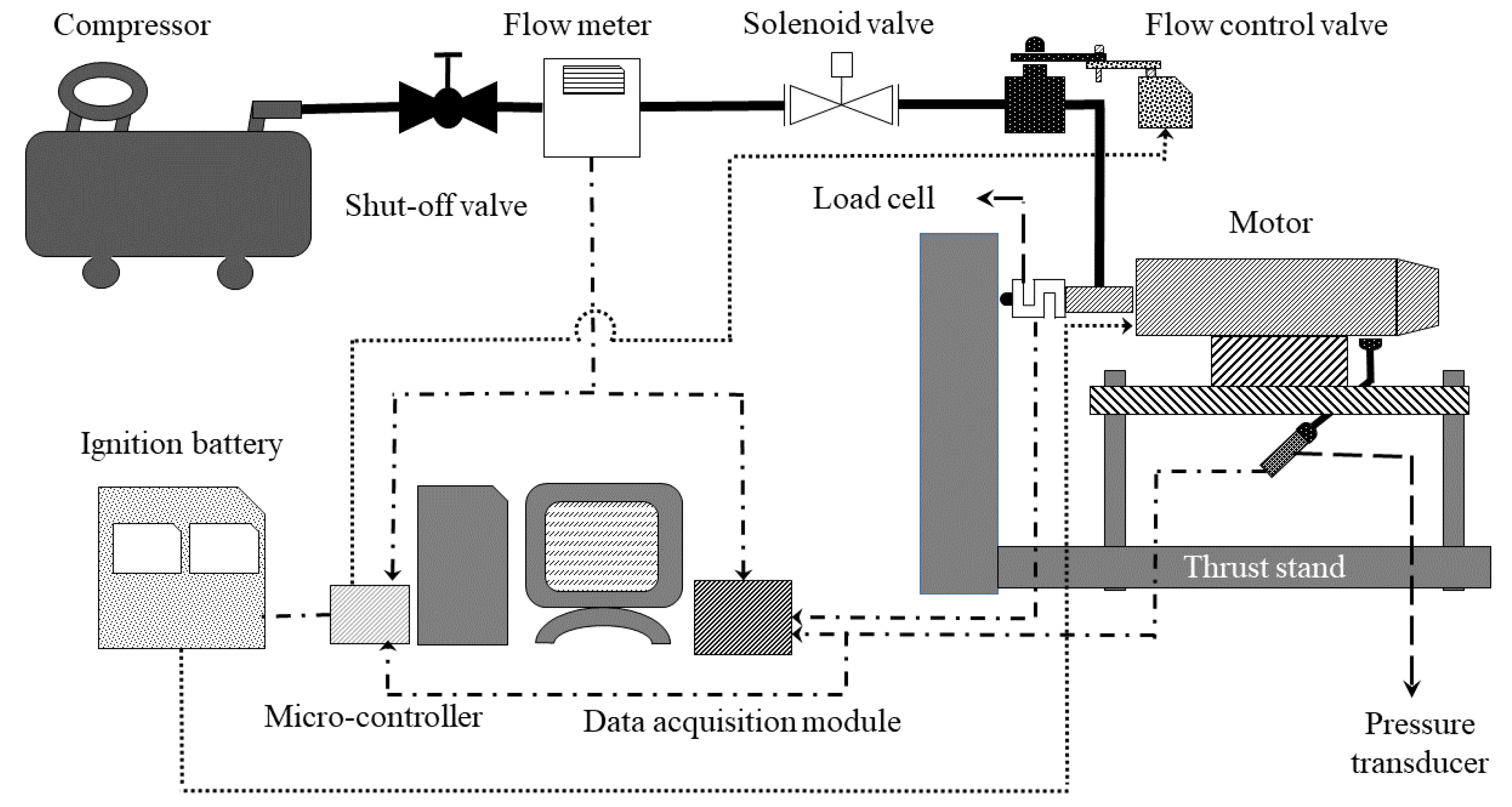
Figure 5 shows the complete schematics of the experimental setup. Table 4 gives the specifications of the measurement instruments. The lab-scale motor tests with constant oxidizer flow rate were carried out for a duration of 20 s. The microcontroller was programmed to initiate the test sequence when the ignition command was given and would shut-off the oxidizer flow after the prescribed duration. The microcontroller was programmed accordingly to perform other tasks such as throttling and closed-loop thrust control. In all tests, the air flow was started after 3 s from the ignition command. This meant that the fuel grain was encountering the combustion of the solid ignitor for the first 3 s, and then there was an overlap of 2 s where ignitor and oxidizer flow were active. This timing was arrived at after multiple experiments. The 3 s of ignitor combustion through the fuel grain port ensured that there was enough hot vaporized fuel to initiate the combustion when the air flow was started. The air flow rates were measured using an off-the-shelf air flow meter. The specifications of the flow meter are given in Table 3. A piezo-resistive pressure sensor was used to measure the chamber pressure, and an S-type load-cell was used to measure the thrust developed. National Instrument’s (NI) data acquisition devices were used to record the data from all the instruments. The burn rate of the propellant combination was estimated using the weight loss method. In this method, the burn rate was calculated from the difference between the fuel grain’s initial and final weights, and port diameters.
3. Simulation Model
The modeling of the hybrid rocket motor was carried out to understand its behavior when a thrust control algorithm is implemented. The current study used a simple mathematical model without explicitly modeling the complex combustion phenomenon and flow dynamics inside a hybrid rocket motor.
At any instant of time, the combustion chamber of the hybrid rocket motor is assumed to be cylindrical with port radius r and length l (length of the fuel grain). Hence, if is the port area, the instantaneous combustion chamber volume or control volume is , and the burning surface area is . For the fuel used in this study, mm. The burn rate of the fuel is of the form
where a and n are constants obtained empirically, and is the mass flux computed as . The experimentally obtained burn rate law of the current propellant is given in Equation (8).
Let be the density of the fuel grain, the density of the combustion gas inside the control volume, and the nozzle throat area with a throat radius of 9 mm. Then, the application of conservation of mass by using a procedure similar to that was used for solid rocket motor by Mukunda [30], giving the differential equation that governs the evolution of chamber pressure as
wherein, unlike in the solid rocket motor case, an additional term of oxidizer mass flow rate will appear. In the current study, is utilized as the control input for regulating the thrust of the hybrid rocket motor. Since, in the experimental setup, the oxidizer flow rate is controlled using a ball valve actuated using a servo motor, a first order model with time constant , which was estimated to be s from the cold flow test data using the System Identification ToolboxTM in MATLAB®, is assumed between the commanded and obtained oxidizer flow rates. That is,
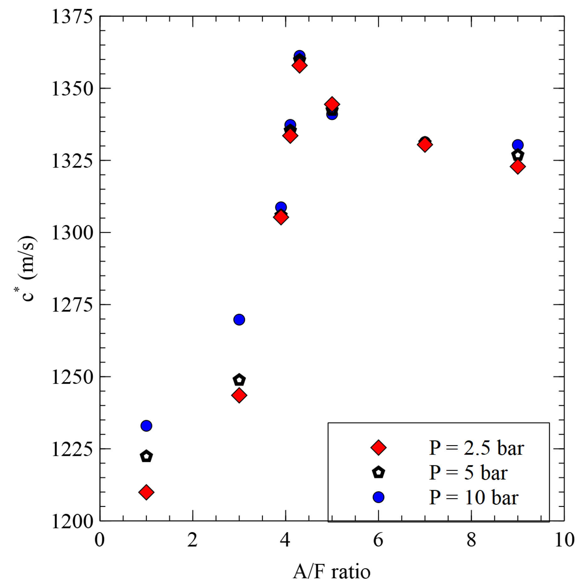
where is the commanded oxidizer flow rate. In Equation (2), and are propellant specific parameters. Here, with being the ratio of heat capacity of the propellant. An estimate of for the current propellant combination is obtained from CEA software (NASA-SP-273) [31] as . The characteristic velocity is a function of and the air to fuel ratio (A/F). Using CEA software, values are obtained for various pressures and A/F for the current fuel composition. The data were computed for pressures ranging from 2 bar to 10 bar at different A/F ratios from 1 to 10. The result of this computation is shown in Figure 6. The value for a given and A/F is then obtained by the linear interpolation of this data.
Equations (1)–(3) are simultaneously solved numerically using the ode45 function of MATLAB with mm, Pa, and kg/s, respectively, as the initial conditions and as the control input. Following Mukunda [30], it is assumed that is small compared to kg/m, and therefore ignored. Once the chamber pressure is known, the thrust produced by the hybrid rocket motor is calculated as
where was also computed using the procedure similar to . The next section describes the computation of the angular opening of the flow control valve which dictated the commanded oxidizer mass flow rate.
4. Control Algorithm
To obtain the oxidizer flow rate required () to control the thrust, this study employs a proportional-integral-derivative (PID) controller with chamber pressure as feedback. PID controller is one of the widely used model-free control algorithms. The PID control input for a system can be written as follows:
where , and are the proportional, integral and derivative gains, respectively. The error, e, is the difference between the desired/reference state and the measured state of the system at time t. is the control input and, in this study, it is the servo angle of the flow control valve in radians. In the simulation studies, to obtain the mass flow rate () of the oxidizer corresponding to the servo angle, a polynomial regression model of the mass flow rate variation based on the result depicted in Figure 4 was used.
The control algorithm can be rewritten as follows for the time step in a discrete-time system:
where is the time interval between two control inputs. Here, the integration is approximated using the trapezoidal rule.
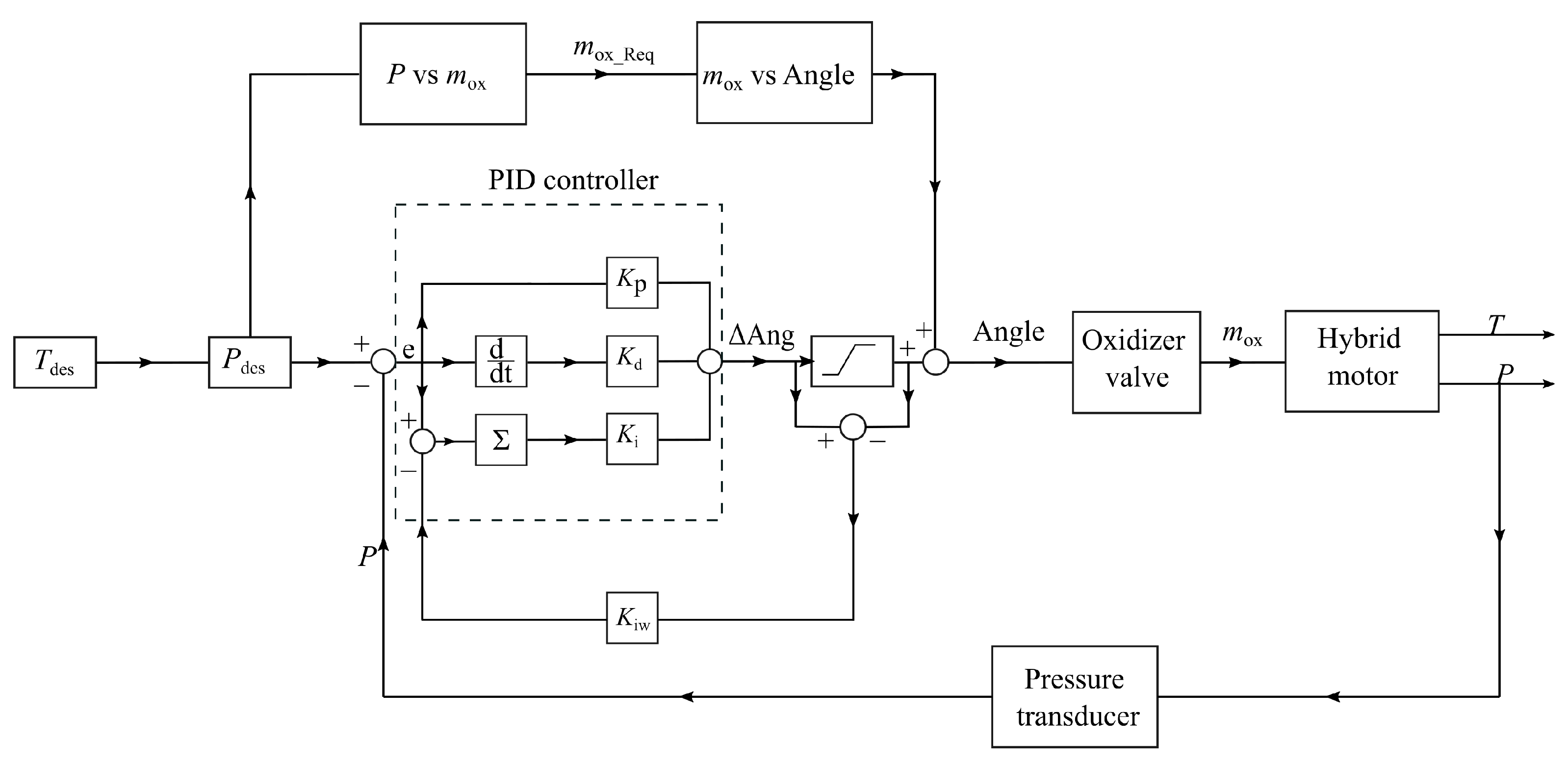
To reduce the response time of the system, a feed-forward loop was also included in the control algorithm [22]. The feed-forward part predicts the required amount of oxidizer flow valve opening to achieve the desired pressure build-up based on the model created from the experimental data. Figure 7 shows the block diagram of the control algorithm. This control algorithm used pressure feedback, whereas the objective of the study is to obtain active thrust control. Pressure feedback was used, keeping in mind the non-feasibility of obtaining a direct thrust measurement from a system in flight. An anti-integral windup loop was also added to the control algorithm to avoid control input saturation due to integral error. The anti-integral windup loop was based on the back-calculation method, which provides supplementary feedback to the integrator whenever there is a control input saturation, and is the gain of the back-calculation method.
5. Results and Discussion
5.1. Characterization of the Motor
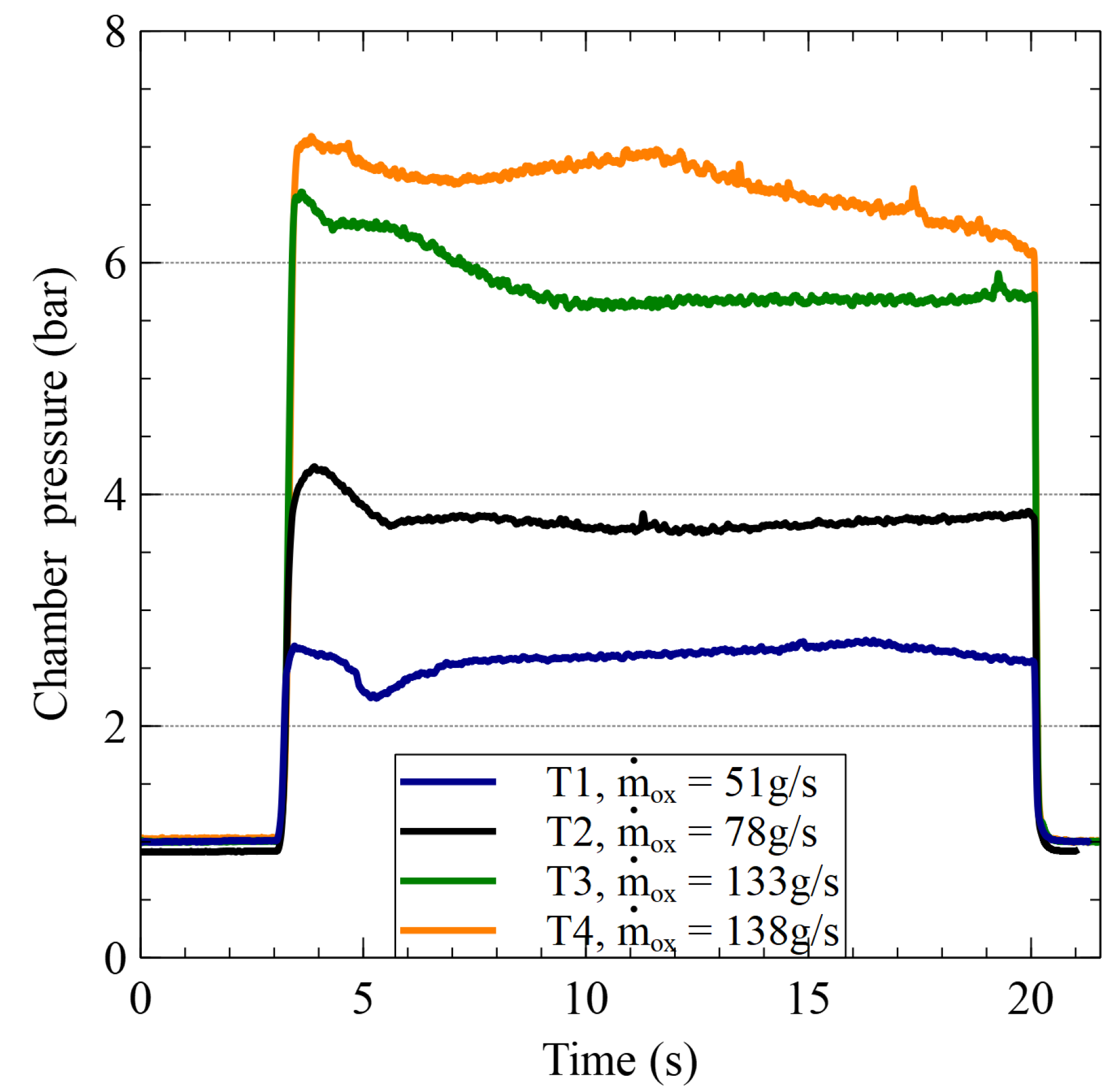
This section presents the results of the open-loop tests to characterize the hybrid rocket motor. In open-loop tests, the oxidizer flow rates were fixed (by fixing the flow control valve angle) to a predetermined value, and the thrust and chamber pressure data were obtained. These data were utilized to derive the empirical burn rate law for the propellant composition given in Table 1. Figure 8 shows the chamber pressure data of some constant flow rate tests. All these tests had a combustion efficiency () in the range of 85–89%, where is defined as the ratio of experimental characteristic velocity and theoretical characteristic velocity (Equation (7))
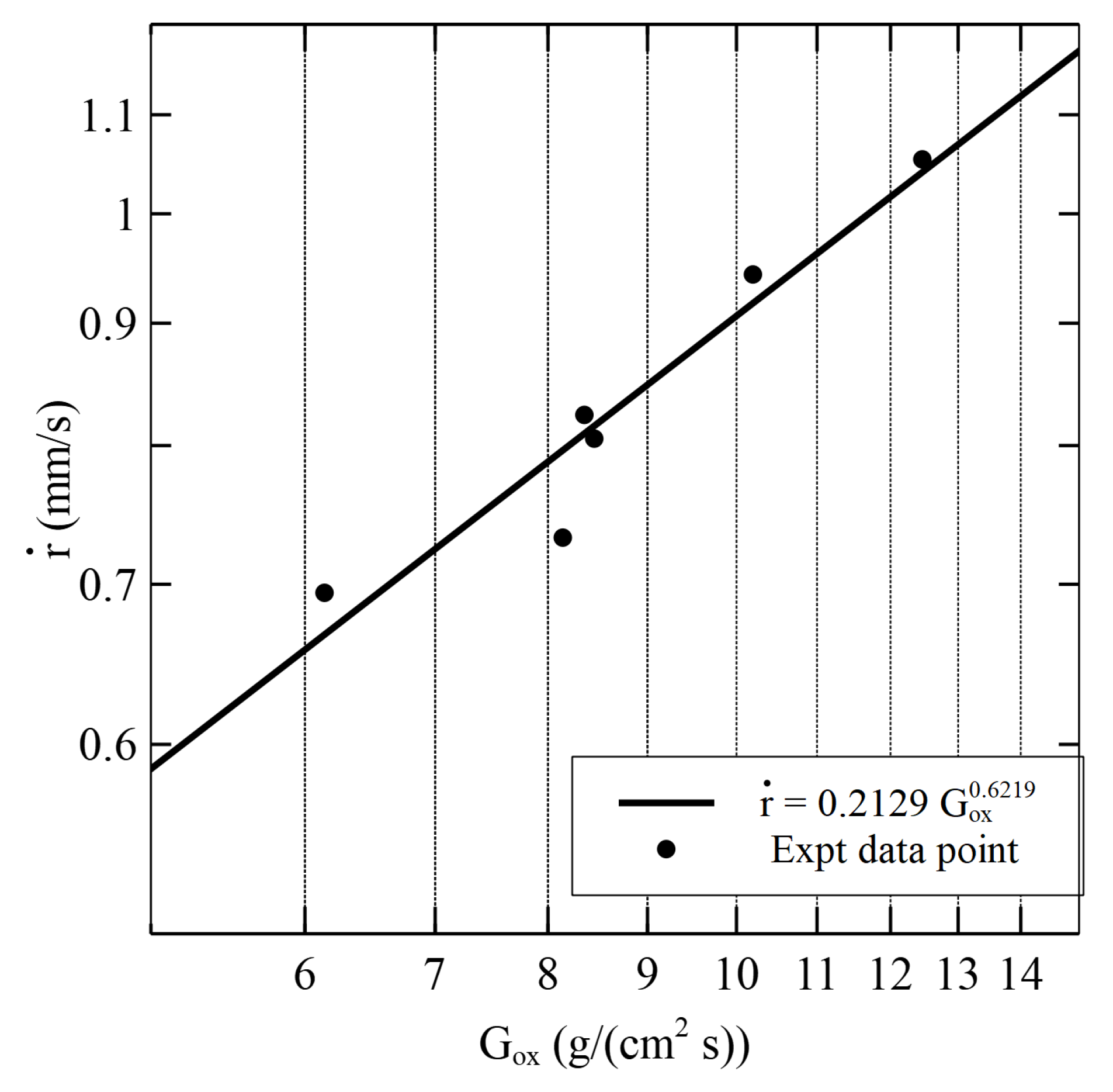
where is the theoretical characteristic velocity obtained from CEA software, and is the characteristic velocity calculated from the experimental results. Figure 9 shows the burn rate obtained from different tests at different oxidizer mass flux. Equation (8) is the empirical burn rate law obtained for the propellant combination.
where is the burn rate in mm/s and is the oxidizer flux in g/(cms).
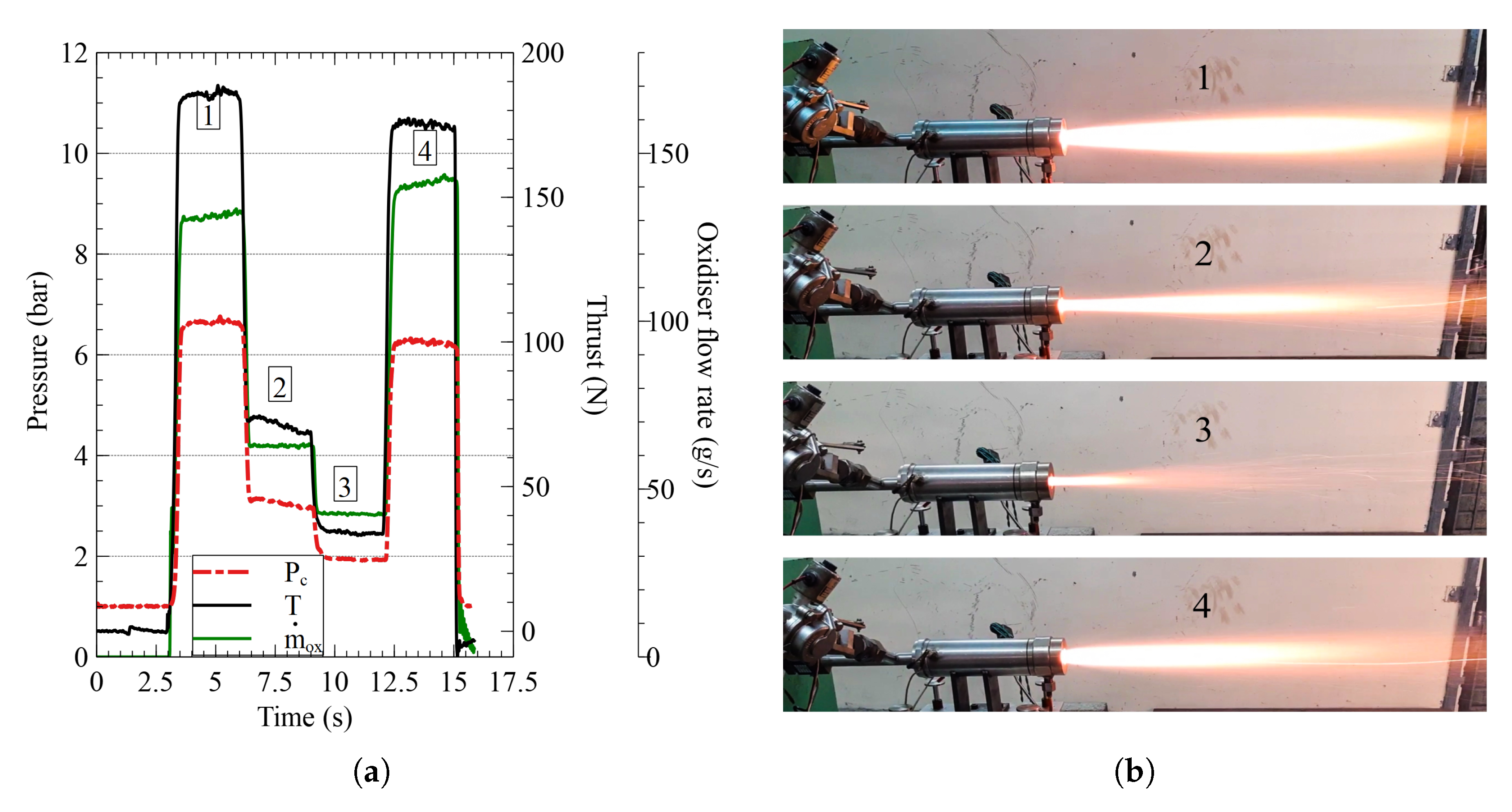
As is evident from the results in Figure 8, the fuel works with air as the oxidizer. This is a significant step towards realizing the VTOL capability of military aircraft because air is abundantly available in these aircraft. To further study the operational limits of the motor in terms of maximum thrust and chamber pressure, throttling tests were carried out. Figure 10 shows the result of a throttling study. The valve opening sequence used in this test was –––. A throttling ratio of 5.5:1 was achieved during this test, with a maximum thrust of N in the first leg of the throttling. The first leg of the throttling has a higher thrust than the last leg, even though the former has a lower oxidizer mass flow rate. This was because, initially, when the port diameter was around 20 mm, the oxidizer flux would be higher and, as the fuel regressed, the oxidizer flux will reduce which in turn reduced the fuel regression rate. From Figure 4, it could be noticed that the flow rate is not in the saturation phase at of valve opening. This indicates that a higher thrust could be obtained if the flow control valve was operated much closer to the saturation region. The limiting condition for that was the chamber pressure developed inside the motor. The oxidizer supply has a settling chamber pressure of 11 bar, and when the flow control valve was operated at the highest flow rate region, the chamber pressure increased to a point where oxidizer flow would not be choked at the inlet of the motor. This leads to coupling between the oxidizer flow and combustion chamber pressure, which is not desirable from a controller point of view.
5.2. Open-Loop Simulation
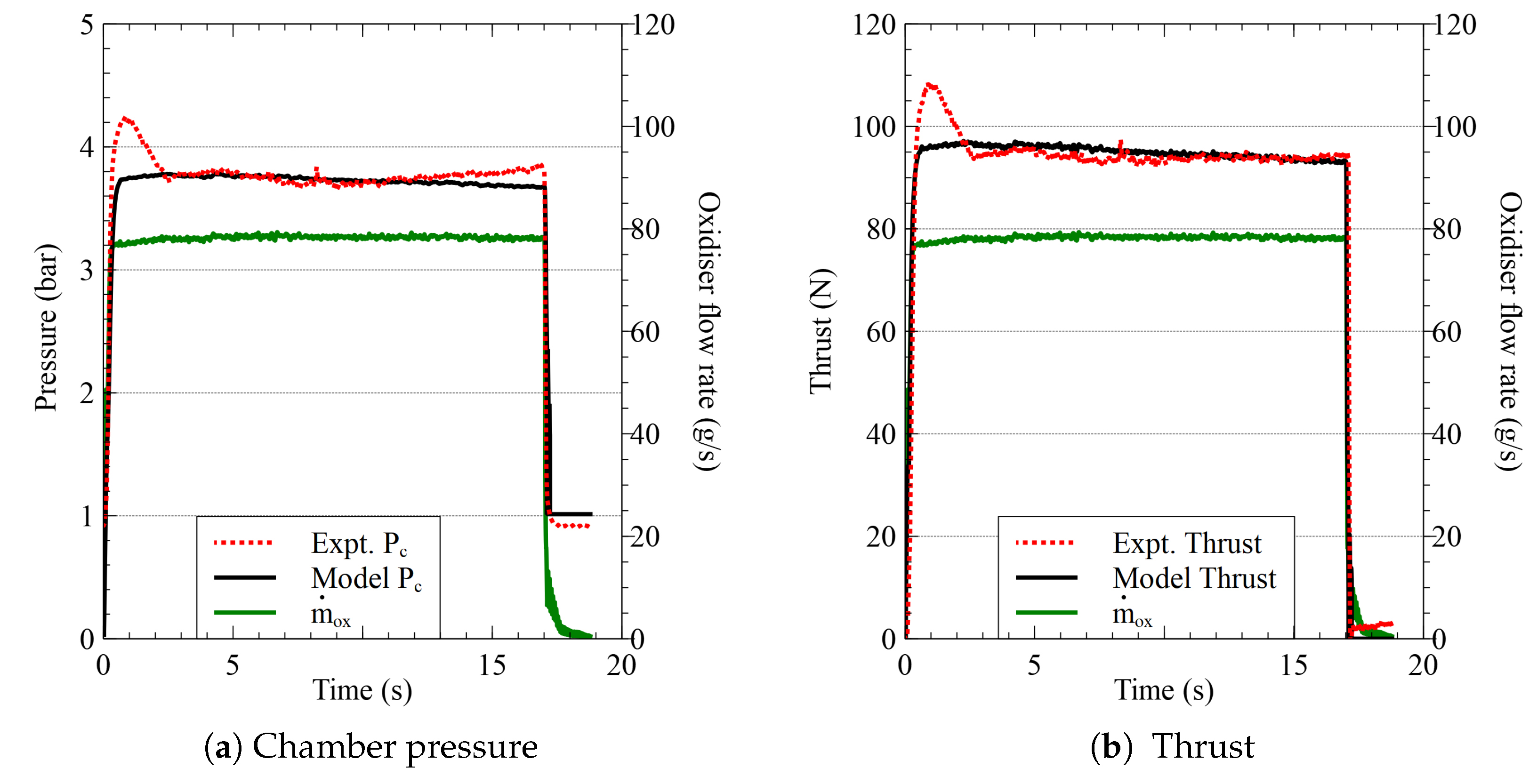
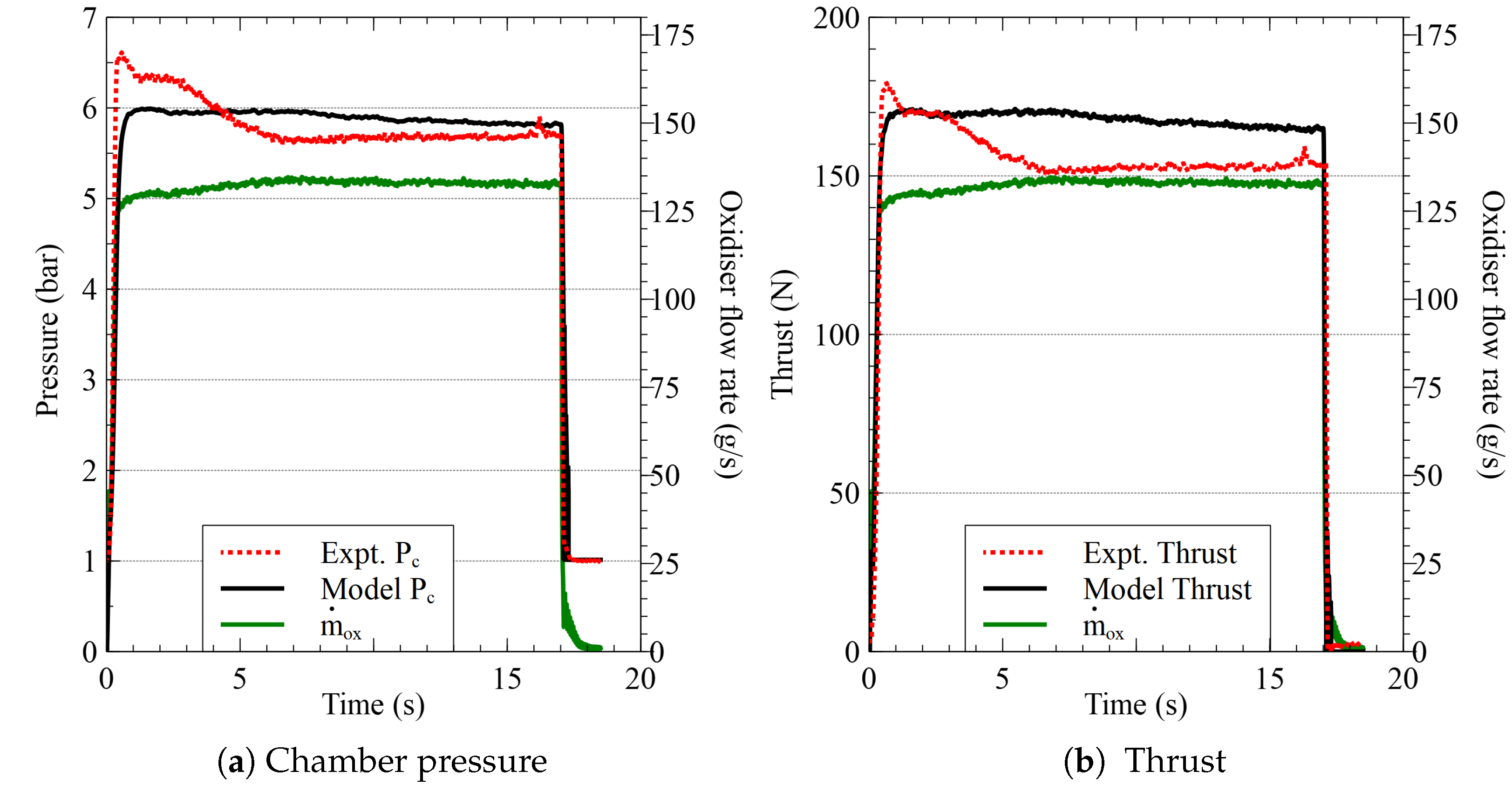
The hybrid rocket model described in Section 3 was used to perform the control algorithm simulations and build an insight into the expected range of PID controller gains. To validate the numerical model with experimental results, the mass flow rate data from the experiments were used as the oxidizer flow rate input for the numerical model. Figure 11 and Figure 12 show the comparison between the experimental chamber pressure and thrust with numerical simulation results. All experimental parameters such as fuel density, length of the fuel, port diameter, etc., are incorporated in the simulation.
In Figure 11 and Figure 12, it can be observed that there is a small peak during the initial two seconds in the experimental data in comparison to the simulation result. This peak observed in the experimental data was because of the overlap between the ignitor and the oxidizer flow rate, and it was not modeled in the simulation. A combustion efficiency () of 85% and a thrust scaling factor of were used in all simulations. These efficiencies were used because the data obtained from CEA software are at equilibrium state. Normally, the experimental data point will be between the equilibrium state and the frozen state. Thus, an efficiency factor was added to compensate for the over-prediction. In the case of the result shown in Figure 12, the chamber pressure and thrust were not closely following the experimental results. This deviation could be due to the constant and scaling factor used in the numerical model. The combustion efficiency will be varying from one test to another when the oxidizer flow rates are changed. The characteristic length , which is defined as , will be the same for all the tests in the starting phase. If is considered as the flow velocity, the residence time could be defined as . A change in would bring about a change in residence time, thus affecting the combustion efficiency. Using a constant value of could be the reason for the mismatch in comparison between simulated thrust and experimental thrust seen in Figure 12. The root-mean-square-error (RMSE) of chamber pressure and thrust for results shown in Figure 12 were bar and N, respectively, whereas, for the case of comparison shown in Figure 11, the RMSE was bar and N, respectively. This was a satisfactory performance for a model that will be used to obtain a first cut understanding of the range of the control gains.
5.3. Closed-Loop Simulation
The objective of the closed-loop simulation study was to obtain an initial set of PID gains for the controller shown in Figure 7. The controller thus tuned was also required to estimate a feed-forward input for a particular reference thrust. To calculate this, a curve fit obtained from the experimental data was utilized. In the experiments, the feedback signal used was the chamber pressure. Therefore, the reference thrust () value was converted to the reference pressure () using the following equation:
where is the throat area, and is the thrust coefficient.
The thrust coefficient given by CEA software does not include the pressure thrust part. Thus, the pressure dependency of thrust coefficient data obtained from CEA software is negligible. To use in Equation (9), the variation of with A/F for the entire range of A/F from 1 to 10 is averaged out to obtain . In the simulation, this was corrected to include the pressure thrust part. Equation (6) was used to estimate the control inputs in simulation, which in this case is the servo angle of the flow control valve in radians. Figure 13 shows the results of control algorithm simulations. In the simulations, the control input was updated at a frequency of 5 Hz and 50 Hz. This was similar to the frequency at which control inputs were updated in experiments. During the experimental study, when multiple thrust commands and ramp input were implemented, the control input was updated at a frequency of 50 Hz to improve the performance for achieving the reference thrust within five seconds. The experimental results obtained are discussed in Section 5.4.2.
In Figure 13, both the simulations used the same control gains, and it can be observed that the response became smoother when the control input frequency was increased. Initially, an offset was observed in the steady-state thrust, which was associated with the assumption which took as a constant, and this affected the estimation of reference pressure. To rectify this, the was further modified iteratively during simulation to reduce the offset in thrust data. The initial s in Figure 13 was the region where the feed-forward part of the controller was active with a constant oxidizer flow rate. The PID controller was activated after s from the ignition command. These simulations are not an exhaustive tuning campaign because the model does not consider many factors affecting an experimental test, such as nozzle deposit/erosion and error in pressure measurement. In these simulations, the aim was not to obtain the optimal control gains but to obtain a range of values around which the experimental system can be tuned. These gains were modified further during the cold flow test described in the next section to achieve a stable steady-state response within a reasonable time scale. Even after this, the control gains required minor tuning when used in a hot flow test described subsequently. Simulations are a better alternative for initial tuning than a hot flow test, which will be time consuming and require more resources. The gains obtained from numerical simulation will help in avoiding situations where the system would go into large-amplitude oscillations while tuning the control gains during a hot-flow test. Figure 14 shows one such result from a hot flow test where the control gains tuning was carried out. The result shows a controller induced oscillation due to improper tuning of the control gains. These scenarios could be avoided to some extent by using the tuning methodology followed in this study. Figure 14 has an initial ramp profile because the feed-forward part of the controller was not implemented in this case.
5.4. Experimental Results
5.4.1. Cold Flow Test
The simulation results described earlier provided an initial guess of gain values that eventually helped in arriving at the final gain configuration. To further refine the gains of the PID controller obtained from simulations, cold flow tests with oxidizer alone were carried out. The only requirement to carry out a cold flow test is a compressed air supply, which makes the tests more effortless and less time-intensive. Multiple trail-and-error corrections of the control gains were carried out without utilizing any fuel grains in comparison to a tuning campaign with a hot flow test. The only change between a hot flow test and a cold flow test is that, in a cold flow, the nozzle chocking occurs at much smaller throat diameters for the same mass flow rates. To obtain a comparable mass flow rate to that of a hot flow test, the nozzle throat diameter in a cold flow test was reduced to 9 mm from 18 mm. The thrust reading is not included in the results of the cold flow test as the thrust readings during these tests are negligible. Figure 15 shows the result of closed-loop control with cold flow. For the step input case in Figure 15a, where the desired chamber pressure was 5.0 bar, the steady-state chamber pressure obtained was bar, and the error was about %. In the test with ramp and step input as shown in Figure 15b, the steady state error for the first two step is % ( bar deviation) and 3% ( bar deviation), respectively. The RMSE during the ramp phase is about bar, which is about % of the final reference value of 5 bar. As these errors were relatively small, this provided the confidence required to go ahead with the hot flow tests.
5.4.2. Hot Flow Test
As discussed, the feedback signal for the closed-loop control algorithm is the chamber pressure. This requires a relationship between thrust and chamber pressure to calculate the reference chamber pressure from the reference thrust value. The theoretical estimation of reference pressure using Equation (9) was not used here due to its inability to predict the reference pressure without modifying the as explained in Section 5.3. Instead of that, an empirical relation between reference thrust and chamber pressure was obtained from experimental data of the constant oxidizer flow rate test (used to obtain the empirical burn rate law) shown in Figure 8. To predict the feed-forward angle, the same set of data was used to obtain a relation between the angular input of the control valve and the chamber pressure produced. A curve fit of the data was obtained to generate the relations required to initiate the closed-loop thrust control tests.
During the course of multiple hot flow tests, the PID gains obtained (Table 5) with cold flow tests were further modified to obtain a better response from the system. Figure 16 shows the result with multiple step input. In this test, the control input frequency used was 50 Hz to improve the performance when the step input duration is only five seconds. The thrust command followed the sequence of 98––98 N (10–12–10 kgf). It can be observed from the result that the pressure response is closely following the reference pressure value. When comparing the average steady-state chamber pressure obtained in different step responses to the corresponding reference values, the highest error among the three was %, which is a deviation of bar observed in the second step. In the case of thrust, the maximum deviation from the reference value was observed in the third step, which was N and is % of the reference thrust of 98 N.
In Figure 16, the oxidizer flow rate for the third step was observed to be higher than that in the first step even though the reference thrust is the same. During the test, the controller is aiming to maintain the reference chamber pressure when there is an increase in the port diameter. For a hybrid rocket motor when , the will be reducing when the port diameter increases [1]. From Equation (8), for the current propellant combination, which indicates that the fuel flow rate will decrease as the port diameter increases. This led to a decrease in the A/F ratio, which would reduce . From Equation (10), it could be observed that, to maintain the reference chamber pressure, the had to be increased to compensate the reduction in and .
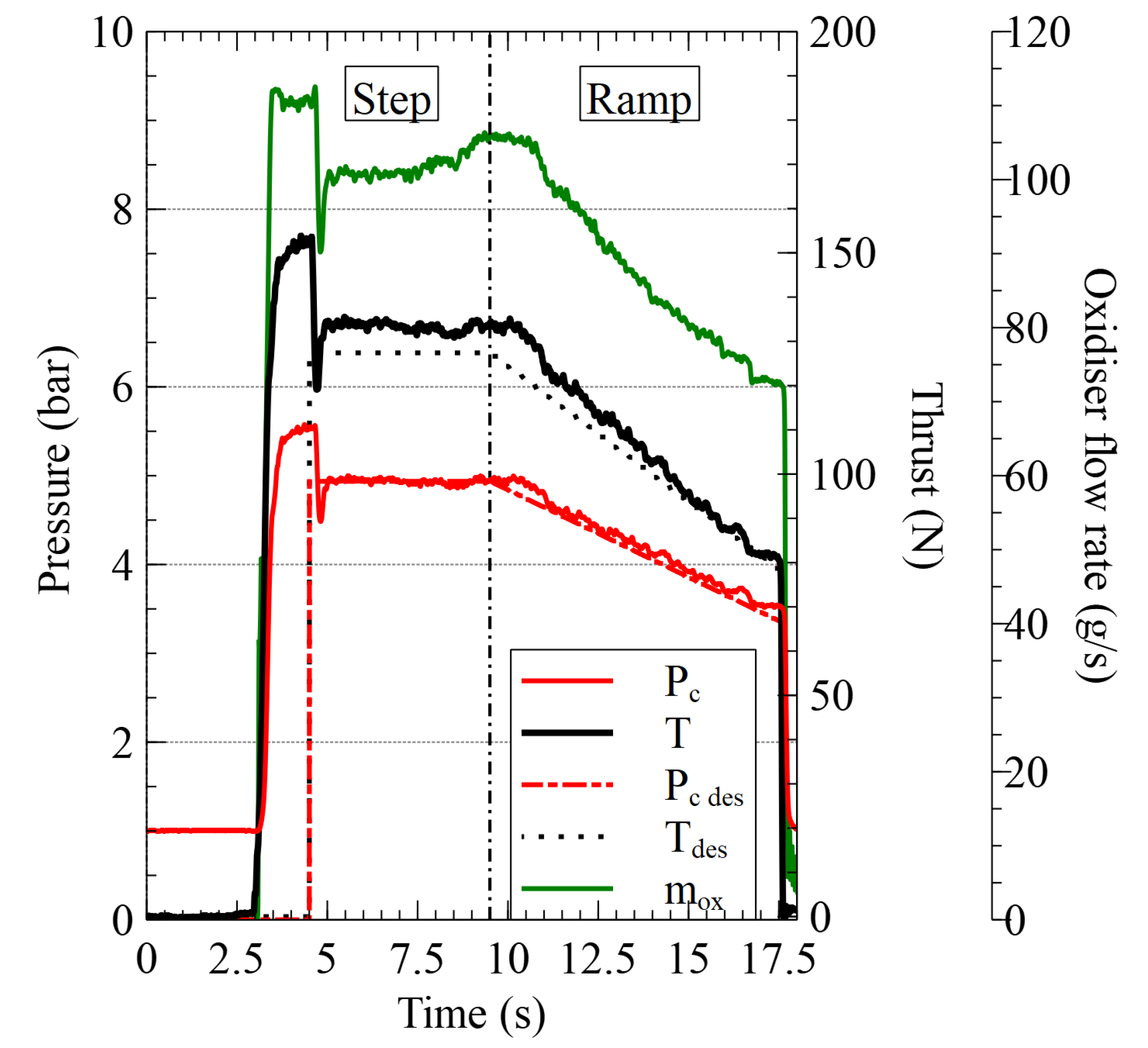
Figure 17 shows the response of the system for a ramp input. The test had one step input and a ramp input command with a linear thrust variation from N (8 kgf) to N (13 kgf). For the step input part, the deviation from the thrust command of 8 kgf was about %, and the variation in chamber pressure was %. In the case of ramp input, the pressure response followed the reference value closely with an RMSE of bar, which is a deviation of %. The measured thrust had a deviation of % with RMSE of N with respect to the maximum thrust achieved.
A ramp-down profile was also tested with the same control algorithm. Figure 18 shows the result of the test. The ramp-down profile will give insight into the performance of the system when utilized for a landing mission which demands a controlled and gradual decrease in the thrust of the lander. The test was carried out with a step input command of N (13 kgf) for five seconds and then a gradual decrease in thrust to achieve the thrust of N (8 kgf). The reference pressure of bar was achieved with a steady-state error of % in the initial step input part, while the measured thrust was observed to have an error of %. The error in the thrust might be due to the error in predicting the reference pressure using the empirical relation between thrust and chamber pressure. The gradual reduction in thrust was achieved with an RMSE error of N and bar.
Table 5 shows the evolution of control gain through various studies. This methodology of obtaining the control gains helped to reduce the number of hot flow tests. Carrying out cold flow tests proved to be a better alternative for initial tuning than hot flow tests, which require more resources in the form of fuel grains and ignitors, which will be time-consuming to prepare and assemble for multiple tests. With lesser resources, the cold flow tests gave a better insight into the system response when different control gains were used.
6. Conclusions
This article reported a systematic study on active thrust control of hybrid rocket motor. Cold compressed air was used as the oxidizer to establish a propellant combination that can be used for VTOL of a military aircraft by utilizing the compressed air from the engines. In addition, the use of air as the oxidizer simplified the lab-scale system. From the available literature, the current study is one among the few to use air at ambient temperature as the oxidizer for a hybrid rocket motor. The fuel used in this motor comprised of aluminum, wax and Viton. Firstly, the propellant combination was characterized to obtain the empirical burn-rate law. A throttling ratio of :1 was obtained during the throttling study of the propellant combination. This showed that the propellant combination with the current flow control system could be used to achieve thrust modulation and active thrust control.
This study used a PID controller with pressure feedback to achieve active thrust control. The PID gain tuning of the system was carried out systematically to reduce the number of hot-flow tests. Numerical simulations and cold flow tests were effectively used to obtain suitable gains that can be used for initial hot flow tests. The numerical model of the hybrid motor was validated using the experimental results. The experimental results and numerical simulations were comparable with an error of bar and N for chamber pressure and thrust prediction. The cold flow tests helped to further refine the control gains before implementing the control algorithm for a hot flow test. Throttling with active thrust control for a reference thrust sequence of 98––98 N was achieved with a maximum error of %, which occurred in the third step. The chamber pressure response obtained in all the tests were closely following the reference pressure value. The response of the system for a ramp input also showed better performance by following the reference profile within N. Similarly, the ramp-down profile also showed good performance with an RMSE error of N.
The results obtained from the lab-scale motor showed that a closed-loop thrust control was achievable with satisfactory confidence using the current propellant combination. The closed-loop control algorithm employed was one of the basic forms of PID controller, and the performance can be improved with more advanced control algorithms. Closed-loop thrust control of hybrid rocket motors will lay the foundation for the development of novel VTOL systems.
Author Contributions
Conceptualization, A.B. and P.A.R.; methodology, A.B., J.G.M. and P.A.R.; validation, A.B.; investigation, A.B.; resources, J.G.M. and P.A.R.; writing—original draft preparation, A.B.; writing—review and editing, A.B., J.G.M. and P.A.R.; supervision, J.G.M. and P.A.R. All authors have read and agreed to the published version of the manuscript.
Funding
This research received no external funding.
Institutional Review Board Statement
Not applicable.
Informed Consent Statement
Not applicable.
Data Availability Statement
Not applicable.
Acknowledgments
We want to acknowledge the valuable contribution of R Siddharth in the development of the flow control valve used in this study.
Conflicts of Interest
The authors declare no conflict of interest.
Nomenclature
| A | = | area, m |
| = | thrust coefficient | |
| = | characteristic velocity, m/s | |
| e | = | error, |
| = | oxidizer mass flux, kg/(s m) | |
| = | specific impulse, N s/kg | |
| K | = | PID gain |
| = | characteristic length, m | |
| = | oxidizer mass flow rate, g/s | |
| n | = | mass flux index |
| P | = | pressure, bar |
| r | = | radius, m |
| = | burn rate, m/s | |
| T | = | thrust, N |
| U | = | control input |
| u | = | exhaust velocity, m/s |
| V | = | volume, m |
| Greek | ||
| = | heat capacity ratio | |
| = | combustion efficiency | |
| = | time constant, s | |
| = | density, kg/m | |
| Subscripts | ||
| b | = | burning surface |
| c | = | combustion chamber |
| d | = | derivative part in PID |
| e | = | nozzle exit |
| f | = | fuel |
| i | = | integral part in PID |
| iw | = | integral wind-up |
| ox | = | oxidizer |
| pt | = | fuel port |
| p | = | proportional part in PID |
| ref | = | reference value for controller |
| t | = | nozzle throat |
Abbreviations
The following abbreviations are used in this manuscript:
| VTOL | Vertical Take-off and Landing |
| HTPB | Hydroxyl-Terminated Polybutadiene |
| PID | Proportional-Integral-Derivative |
| RMSE | Root-mean-square-error |
References
- Biblarz, O.; Sutton, G.P. Rocket Propulsion Elements; Wiley India: New Delhi, India, 2014; Chapter 15; pp. 579–606. [Google Scholar]
- Jens, E.T.; Cantwell, B.J.; Hubbard, G.S. Hybrid Rocket Propulsion Systems for Outer Planet Exploration Missions. Acta Astronaut. 2016, 128, 119–130. [Google Scholar] [CrossRef]
- Lee, D.; Han, S.; Moon, H. Development of 200 N-class Throttleable Hybrid Rocket Motor for Lunar Module Application. FirePhysChem 2021, 1, 251–259. [Google Scholar] [CrossRef]
- Parissenti, G.; Pessana, M.; Gaia, E.; Zaccagnino, E.; Santilli, F.; Pavarin, D.; Bettella, A.; Ronningen, J.E.; Van Put, P.; Tijsterman, R.; et al. Throttleable Hybrid Engine for Planetary Soft Landing. In Proceedings of the 4th European Conference for Aerospace Sciences, Saint Petersburg, Russia, 4–8 July 2011; EUCASS Association: Brussels, Belgium, 2011. [Google Scholar]
- Karabeyoglu, M.A.; Altman, D.; Cantwell, B.J. Combustion of Liquefying Hybrid Propellants: Part 1, General Theory. J. Propuls. Power 2002, 18, 610–620. [Google Scholar] [CrossRef]
- Smoot, L.D.; Price, C.F. Regression Rates of Metalized Hybrid Fuel Systems. AIAA J. 1966, 4, 910–915. [Google Scholar] [CrossRef]
- Strand, L.D.; Ray, R.L.; Anderson, F.A.; Cohen, N.S. Hybrid Rocket Fuel Combustion and Regression Rate Study. In Proceedings of the 28th AIAA/ASME/SAE/ASEE Joint Propulsion Conference and Exhibit, Nashville, TN, USA, 6–8 July 1992. AIAA Paper 1992–3302. [Google Scholar] [CrossRef]
- Chiaverini, M.J.; Serin, N.; Johnson, D.K.; Lu, Y.; Kuo, K.K.; Risha, G.A. Regression Rate Behavior of Hybrid Rocket Solid Fuels. J. Propuls. Power 2000, 16, 125–132. [Google Scholar] [CrossRef]
- Paravan, C. Nano-Sized and Mechanically Activated Composites: Perspectives for Enhanced Mass Burning Rate in Aluminized Solid Fuels for Hybrid Rocket Propulsion. Aerospace 2019, 6, 127. [Google Scholar] [CrossRef]
- Thomas, J.C.; Petersen, E.L.; DeSain, J.D.; Brady, B.B. Enhancement of Regression Rates in Hybrid Rockets with HTPB Fuel Grains by Metallic Additives. In Proceedings of the 51st AIAA/SAE/ASEE Joint Propulsion Conference, Orlando, FL, USA, 27–29 July 2015. AIAA Paper 2015–4041. [Google Scholar] [CrossRef]
- Kumar, R.; Ramakrishna, P. A. Enhancement of Hybrid Fuel Regression Rate Using a Bluff Body. J. Propuls. Power 2014, 30, 909–916. [Google Scholar] [CrossRef]
- Kumar, R.; Ramakrishna, P.A. Effect of Protrusion on the Enhancement of Regression Rate. Aerosp. Sci. Technol. 2014, 39, 169–178. [Google Scholar] [CrossRef]
- Chen, S.; Tang, Y.; Zhang, W.; Shen, R.; Yu, H.; Ye, Y.; DeLuca, L.T. Innovative Methods to Enhance the Combustion Properties of Solid Fuels for Hybrid Rocket Propulsion. Aerospace 2019, 6, 47. [Google Scholar] [CrossRef]
- Waidmann, W. Thrust Modulation in Hybrid Rocket Engines. J. Propuls. Power 1988, 4, 421–427. [Google Scholar] [CrossRef]
- Marothiya, G.; Ramakrishna, P.A.; Saravanan, N.; Kumar Solasa, P. Development of H2O2 Based Mixed Hybrid Rocket. Propellants Explos. Pyrotech. 2021, 46, 1687–1695. [Google Scholar] [CrossRef]
- Austin, B.; Heister, S.; Dambach, E.; Meyer, S.; Wernimont, E. Variable Thrust, Multiple Start Hybrid Motor Solutions for Missile and Space Applications. In Proceedings of the 46th AIAA/ASME/SAE/ASEE Joint Propulsion Conference & Exhibit, Nashville, TN, USA, 25–28 July 2010. AIAA Paper 2010–7121. [Google Scholar] [CrossRef]
- Zhao, S.; Cai, G.; Tian, H.; Yu, N.; Zeng, P. Experimental Tests of Throttleable H2O2/PE Hybrid Rocket Motors. In Proceedings of the 51st AIAA/SAE/ASEE Joint Propulsion Conference, Orlando, FL, USA, 27–29 July 2015. AIAA Paper 2015–3831. [Google Scholar] [CrossRef]
- Ruffin, A.; Paccagnella, E.; Santi, M.; Barato, F.; Pavarin, D. Real Time Deep Throttling Tests of a Hydrogen Peroxide Hybrid Rocket Motor. In Proceedings of the AIAA Propulsion and Energy Forum and Exposition, Indianapolis, IN, USA, 19–22 August 2019. AIAA Paper 2019–4266. [Google Scholar] [CrossRef]
- Whitmore, S.A.; Peterson, Z.W.; Eilers, S.D. Deep Throttle of a Nitrous Oxide and Hydroxyl-Terminated Polybutadiene Hybrid Rocket Motor. J. Propuls. Power 2014, 30, 78–86. [Google Scholar] [CrossRef]
- Whitmore, S.A.; Peterson, Z.W.; Eilers, S.D. Closed-Loop Precision Throttling of a Hybrid Rocket Motor. J. Propuls. Power 2014, 30, 325–336. [Google Scholar] [CrossRef]
- Choi, J.S.; Kang, W.; Huh, H. Study of Thrust Control Performance Improvement for Hybrid Rocket Applications. J. Korean Soc. Propuls. Eng. 2011, 15, 55–62. Available online: https://www.koreascience.or.kr/article/JAKO201131263122700.page (accessed on 8 August 2021).
- Velthuysen, T.; Brooks, M.; Pitot, J. Closed Loop Throttle Control of a Liquefying Fuel Hybrid Rocket Motor. J. Aerosp. Technol. Manag. 2021, 13. [Google Scholar] [CrossRef]
- Messineo, J.; Shimada, T. Theoretical Investigation on Feedback Control of Hybrid Rocket Engines. Aerospace 2019, 6, 65. [Google Scholar] [CrossRef] [Green Version]
- Whitmore, S.A.; Bulcher, A.M. A Green Hybrid Thruster Using Moderately Enriched Compressed Air as the Oxidizer. In Proceedings of the 2018 Joint Propulsion Conference, Cincinnati, OH, USA, 9–11 July 2018. AIAA Paper 2018–4841. [Google Scholar] [CrossRef]
- Schulte, G. Fuel Regression and Flame Stabilization Studies of Solid-Fuel Ramjets. J. Propuls. Power 1986, 2, 301–304. [Google Scholar] [CrossRef]
- Netzer, A.; Gany, A. Burning and Flameholding Characteristics of a Miniature Solid Fuel Ramjet Combustor. J. Propuls. Power 1991, 7, 357–363. [Google Scholar] [CrossRef]
- Verma, S.; Ramakrishna, P.A. Effect of Specific Surface Area of Aluminum on Composite Solid Propellant Burning. J. Propuls. Power 2013, 29, 1200–1206. [Google Scholar] [CrossRef]
- Marothiya, G.; Ramakrishna, P.A. Coating Viton on Flake Aluminum and its Effects on Performance of Solid Rocket Motor. Int. J. Energetic Mater. Chem. Propuls. 2022, 21, 73–85. [Google Scholar] [CrossRef]
- Wollmark, S.; Yavor, Y. Burning Rates of Nanoaluminum—Water Solid Propellants at Various Pressures. J. Propuls. Power 2019, 35, 173–181. [Google Scholar] [CrossRef]
- Mukunda, H.S. Understanding Aerospace Chemical Propulsion; IK International Publishing House: New Delhi, India, 2017; Chapter 9; pp. 309–350. [Google Scholar]
- Gordon, S.; Mcbride, B.J. Computer Program for Calculation of Complex Chemical Equilibrium Compositions and Applications II. Users Manual and Program Description. NASA-RP-1311; June 1996. Available online: https://ntrs.nasa.gov/citations/19960044559 (accessed on 3 October 2018).
Figure 1.
Conceptual diagram of VTOL mechanism (Note that multiple hybrid rockets will be used in the proposed system).
Figure 1.
Conceptual diagram of VTOL mechanism (Note that multiple hybrid rockets will be used in the proposed system).

Figure 2.
Schematic of the hybrid rocket motor.

Figure 3.
Flow control valve.

Figure 4.
Air flow rate versus servo angle.

Figure 5.
Schematic of experimental setup.

Figure 6.
data obtained from CEA software.

Figure 7.
Block diagram of the controller.

Figure 8.
Open-loop test with constant oxidizer flow rate.

Figure 9.
Burn rate versus oxidizer flux obtained from open loop tests.

Figure 10.
Throttling study. (a) pressure and thrust profile; (b) steps in throttling.

Figure 11.
Comparison between experimental and numerical simulation results at a lower oxidizer mass flow rate.
Figure 11.
Comparison between experimental and numerical simulation results at a lower oxidizer mass flow rate.

Figure 12.
Comparison between experimental and numerical simulation results at a higher oxidizer mass flow rate.
Figure 12.
Comparison between experimental and numerical simulation results at a higher oxidizer mass flow rate.

Figure 13.
Simulation results of closed-loop thrust control algorithm where 98 N (10 kgf), and bar. (a) control input interval ms (5 Hz); (b) control input interval ms (50 Hz).
Figure 13.
Simulation results of closed-loop thrust control algorithm where 98 N (10 kgf), and bar. (a) control input interval ms (5 Hz); (b) control input interval ms (50 Hz).

Figure 14.
High amplitude oscillations during hot flow test due to improper PID gains.

Figure 15.
Closed-loop thrust control result with oxidizer alone—cold flow test. (a) step input, bar; (b) closed-loop thrust control result with oxidizer alone—cold flow test.
Figure 15.
Closed-loop thrust control result with oxidizer alone—cold flow test. (a) step input, bar; (b) closed-loop thrust control result with oxidizer alone—cold flow test.

Figure 16.
Throttling with active control.

Figure 17.
Step and ramp input response.

Figure 18.
Ramp-down profile.


Table 1.
Fuel parameters.
| Parameter | Value |
|---|---|
| Wax | 50% |
| Pyral (Al) | 42.5% |
| Viton | 7.5% |
| A/F for maximum | 4.7 |
Table 2.
Fuel ingredients.
| Ingredients | Density (kg/m) | Source |
|---|---|---|
| Wax | 900 | Mahatha Petroleum Pvt. Ltd., Chennai, India |
| Pyral (Al) | 2700 | Thangamani Trading Company, Chennai, India |
| VitonTM | 1840 | The Chemours Company, Wilmington, DE, USA |
Table 3.
Specifications of flow control valve components.
| Component | Specification | |
|---|---|---|
| Valve | Type | Ball valve |
| Working pressure | up to 25 bar | |
| End connections | inch BSP | |
| Servo motor | Stall torque | 35 kg·cm @ V |
| Operating voltage | 6 to V | |
| Operating speed | s/60 | |
Table 4.
Specifications of equipment.
| Equipment | Specification | |
|---|---|---|
| Flow meter | Model | Festo SFAM 90 |
| Measuring principle | Thermal | |
| Measurement range | 0 to lpm | |
| Pressure sensor | Model | GE UNIK 5000 |
| Sensor | Piezo-resistive | |
| Measurement range | 0 to 35 bar absolute | |
| Load cell | Model | IPA DS022H0 |
| Type | Double S | |
| Maximum capacity | 200 kg | |
Table 5.
PID control gains.
| Study | K | K | K |
|---|---|---|---|
| Simulation | 0.12 | 0.001 | 0.8 |
| Cold-flow test (step) | 0.2 | 0.02 | 0.3 |
| Cold-flow test (step and Ramp) | 0.2 | 0.02 | 0.5 |
| Hot-flow test (step and Ramp) | 0.2 | 0.018 | 0.48 |
Publisher’s Note: MDPI stays neutral with regard to jurisdictional claims in published maps and institutional affiliations. |
© 2022 by the authors. Licensee MDPI, Basel, Switzerland. This article is an open access article distributed under the terms and conditions of the Creative Commons Attribution (CC BY) license (https://creativecommons.org/licenses/by/4.0/).
Share and Cite
MDPI and ACS Style
Bhadran, A.; Manathara, J.G.; Ramakrishna, P.A. Thrust Control of Lab-Scale Hybrid Rocket Motor with Wax-Aluminum Fuel and Air as Oxidizer. Aerospace 2022, 9, 474. https://doi.org/10.3390/aerospace9090474
AMA Style
Bhadran A, Manathara JG, Ramakrishna PA. Thrust Control of Lab-Scale Hybrid Rocket Motor with Wax-Aluminum Fuel and Air as Oxidizer. Aerospace. 2022; 9(9):474. https://doi.org/10.3390/aerospace9090474
Chicago/Turabian StyleBhadran, Anandu, Joel George Manathara, and P. A. Ramakrishna. 2022. "Thrust Control of Lab-Scale Hybrid Rocket Motor with Wax-Aluminum Fuel and Air as Oxidizer" Aerospace 9, no. 9: 474. https://doi.org/10.3390/aerospace9090474
Note that from the first issue of 2016, this journal uses article numbers instead of page numbers. See further details here.