
Gust Alleviation and Wind Tunnel Test by Using Combined Feedforward Control and Feedback Control


School of Aeronautic Science and Engineering, Beihang University, Beijing 100191, China
*
Author to whom correspondence should be addressed.
Aerospace 2022, 9(4), 225; https://doi.org/10.3390/aerospace9040225
Submission received: 31 January 2022
/
Revised: 31 March 2022
/
Accepted: 11 April 2022
/
Published: 18 April 2022
(This article belongs to the Section Aeronautics)
Abstract
:Gust alleviation is of great significance for improving aircraft ride quality and reducing gust load. Using aircraft response (feedback control) and gust disturbance information (feedforward control) to improve the gust alleviation effect is worthy of attention. In this paper, a combined control system (CCS) composed of feedforward control system (FFCS) and feedback control system (FBCS) is designed and analyzed. At the same time, the gust alleviation effect of the CCS, the single FFCS and the single FBCS are analyzed and compared by means of numerical simulation and wind tunnel test, respectively. Taking a flexible wing as the research object, the gust alleviation effects of three control systems under different forms of gust excitation (1-cos discrete gust, sine gust and Dryden turbulence) are analyzed by numerical simulation. In the wind tunnel test, the sine gust generated by a gust generator was used, and the gust alleviation test was carried out under different wind speeds and gust frequencies. The simulation and experimental results show that the CCS has better gust alleviation performance for various gust excitations. When comparing FFCS and FBCS, the FFCS has better robustness and control effect than the FBCS. When comparing FFCS and CCS, the better the alleviation effect of FFCS, the more difficult it is to achieve significant effect improvement by using CCS, which is obtained by adding FBCS on the FFCS.
1. Introduction
The influence of atmosphere gusts on aircraft flight cannot be ignored. On the one hand, gusts can cause aircraft vibration response, reduce the ride quality and increase the difficulty of pilots’ manipulation; on the other hand, it will also increase the load on the aircraft body and shorten the fatigue life of the structure, which may require additional strengthening of the structure and result in increased weight of the aircraft. With the increasing flexibility of modern aircraft, gusts will lead to a larger vibration response. Aircrafts with a large number of composite materials [1] or with wing-body layout [2] have smaller wing load, and gusts have a greater impact on such kinds of aircraft. In order to cope with the gusts’ influence, active control technology is an effective method for achieving gust alleviation.
Since the 1950s, a lot of research on gust alleviation based on active control technology has been carried out, most of which was based on feedback control. Feedback control means that when the aircraft is disturbed by gusts, the available sensors measure the gust response signals (such as acceleration, pitch angle velocity), and the control system uses these signals as the input to achieve gust alleviation. These sensors mainly include the accelerometer, angular rate gyro, angular displacement meter, etc. PID control is a commonly used method for designing gust alleviation system (GAS) in classical control theory [3]. With the development of control theory, pole assignment [4,5], LQG control [6,7,8], robust control represented by control to overcome model uncertainty [9,10,11], model predictive control [12,13] that can consider actuator constraints, and the combination of these methods [14] are used to design GAS. In recent years, some authors have carried out the research on intelligent GAS based on neural network-fuzzy control [15,16]. In addition to theoretical research, a large number of wind tunnel tests [17,18,19,20], flight tests [21,22,23] and practical applications have been carried out in terms of gust alleviation feedback control. The practical aircrafts equipped with GAS include, but are not limited to, Airbus A320, A380 and Boeing B-787 aircraft [24].
However, the GAS based on feedback control also has some shortcomings; for example, the alleviation effect is limited by the performance of the actuator system, and the control system designed for specific working stations has poor effect in other conditions. At the same time, the feedback control belongs to the closed-loop control, and the selection of its control parameter has a great influence on the stability of the aeroservoelastic system. As a result, the feedforward open-loop control method with gust as input has entered people’s vision. With the development of gust detection technology, this control method has attracted more and more attention. At present, the detection of gust information is mainly carried out by using light detection and ranging (LIDAR) system [25] and angle of attack (AOA)/angle of sideslip (AOS) sensor [26]. The LIDAR system detection distance is long, and the range is wide, but the weight is large, and the gust calculation method is complicated, so the LIDAR system is suitable for larger aircraft. The gust area detected by the AOA/AOS sensor is narrow, the sensor only detects the gust at its own location. For general aviation aircraft or UAV, due to the limitation of the size or weight of the aircraft, it is more appropriate to reduce the gust load based on this kind of sensor. Therefore, it is of great significance to study the feedforward gust alleviation method based on the AOA/AOS sensor.
Scholars designed FFCS through a variety of control methods, such as adaptive control system based on the least mean square (LMS) algorithm [27], circular leaky least mean square (CCLMS) algorithm [28], orthonormal basis expansions along with recursive least square (RLS) algorithm [29] and robust control system [30] based on theory. These feedforward control systems showed promising results through simulation. In order to further improve the performance of the control system, some scholars also began to study the combination of FBCS and FFCS. Through the introduction of FBCS, the response caused by short-scale gusts can be better suppressed [2]. At present, the experimental research on feedforward control is not sufficient. Researchers [26] from Germany installed airflow angle sensors on ATTAS aircraft to detect gusts and carried out flight tests. The test result shows that the FFCS can suppress wing bending vibration caused by gusts. There are also some feedforward flight tests [31,32], but in these studies, direct gust measurements were not performed, disturbance was generated by driving the control surface on the aircraft to simulate gust excitation, and the perturbed drive signal was used as the input of the FFCS. Researchers in Germany [33] and Japan [34] also carried out the wind tunnel test of feedforward control, and the gust input signal in the FFCS was indirectly replaced by the control command signal of the gust generator. By reviewing the existing research, it can be found that the research about the combination of feedforward control and feedback control, and the analysis and comparison of their control characteristics are not sufficient. At the same time, relevant experiments still need to be carried out.
In this study, the modeling method of the aeroelastic system and the gust model are described at first. Then, based on the state-space model of a wing, CCS, FFCS and FBCS are designed and simulated. Furthermore, in the wind tunnel test, the gust information measured by the five-hole probe is used as the input of the simplified FFCS; the acceleration of wingtip is used as the input of FBCS; and the alleviation effect of three types of control system is experimentally studied by sine gust with various wind speeds and gust frequencies.
2. Aeroelastic System Modeling and Gust Model
2.1. Aeroelastic System Modeling
In the complex frequency domain space, the dynamic equation of the aeroelastic system under gust excitation can be expressed by [35]
where is the generalized mass matrix; is the inertial mass matrix of control surface; and are generalized damping and stiffness matrixes, respectively; , , are the generalized aerodynamic matrix corresponding to generalized displacement, control surface deflection angle and gusts, respectively; is the generalized displacement matrix; is the control surface deflection angle vector; is gust velocity; is the air density; and is flight speed. The generalized mass matrix and inertial mass matrix can be further expressed as
where is the structural modal matrix; is the control surface deflection modal matrix; and is the mass matrix generated by the structural finite element model. The generalized stiffness and damping matrix can be expressed as
where and are the frequency and damping ratio corresponding to ith mode, respectively; is the ith element on the diagonal of and is a square matrix with dimension . It should be noted that, for the rigid-body modes, should be set to zero.
The frequency domain aerodynamic force is calculated by the double-lattice method in the present work, and the gust response can be directly calculated according to Equation (1) in the frequency domain. When the control law is designed in the time domain, the minimum state method [4] can be used to transform the aerodynamic force in the frequency domain into the time domain. In the Laplace domain, the generalized aerodynamic force influence coefficient matrix can be fitted by real matrixes through the following relationship:
where is the fitted frequency domain aerodynamic influence coefficient matrix; , , and are fitting polynomial coefficient matrixes, it should be noted that the corresponding to the gust is usually set to zero to avoid the coefficient related to the second derivative of the gust velocity [36]; is the aerodynamic lag root coefficient matrix, which usually chosen to be diagonal with negative elements [4]. is the dimensionless Laplace variable, since the aerodynamic influence coefficient matrix is calculated in the frequency domain, and the matrix is related to the reduced frequency, the real fitting matrixes for state-space modeling is obtained by set , is reduced frequency and . The aerodynamic forces corresponding to generalized displacement, control surface deflection and gusts can be fitted at the same time, and then, each fitting matrix in Equation (2) can be written in the following block form:
Introducing an aerodynamic state function as
by converting the aerodynamic force into the time domain and applying the inverse Laplace transform to Equation (1), the state-space model of the aeroelastic system can be obtained as follows:
where is the state matrix; is the control surface deflection angle input matrix; and is gust input matrix. The state vector and input vector are defined by
2.2. System Output
For the gust response and alleviation problem, what is usually concerned is the motion response at some key positions (such as the wingtip, center of gravity) and the load response at key parts (such as the wing root). Acceleration responses at specific location can be obtained by
where is the modal vector at the location. As for the load at the critical section, it can be obtained by the modal displacement method. Supposing the displacement at a certain point of the structure is , then the relationship between the internal force and the displacement at this point can be expressed as
where is the element stiffness matrix. Thus, the model state-space equation containing the output can be written as
where is the output matrix; and are output matrixes related to control surface deflection angle and gusts, respectively. The output vector is defined as
2.3. State-Space Model of Actuator
The characteristics of the actuator system are very important for the GAS, so the actuator model needs to be considered in the state-space equation. In the aeroelastic active control, it is common to use the electric actuator or electro-hydraulic servo actuator to drive the control surface. Generally, the second-order or third-order transfer function can approximately describe the physical characteristics of these actuators. At the same time, since the second-order derivative term of the deflection angle of the actuator needs to be used when establishing the state-space model, we usually choose a third-order transfer function as the actuator model. The mathematical model of the ith actuator can usually be expressed by [37]:
written in the form of a state-space model:
In the above formula, the control command is calculated by the GAS, and the final output is the control surface deflection angle obtained by the above state-space model. If there are m actuators, the compact form of Equation (11) should be as follows:
where
the size of above is .
2.4. Gusts Modeling
Atmospheric disturbance is a very complex physical phenomenon, including spatial and temporal changes (temperature, pressure, wind speed, etc.), and the mechanisms and physical processes that cause atmospheric changes (such as terrain changes, rainy and snowy weather, etc.) are completely different. In terms of gust response analysis and gust alleviation, scholars mainly study the influence of the change of air velocity (wind speed) on the aircraft, while other factors (such as pressure changes, temperature changes and the cause of wind, etc.) are ignored as secondary factors in the gust model. Therefore, the simplified atmospheric disturbance models can be adopted when analyzing the impact of gusts on aircraft. These simplified models of atmospheric disturbances are gradually summarized through long-term observational statistics and research.
In the initial stage of research on gusts, scholars put forward the “sharp-edged” gust model [38], which is very simple; later, scholars developed the “1-cos” discrete gust model [39], which can consider the pitching motion effect of aircraft when entering the gust area. With further in-depth study and the acquisition of a large amount of gust measurement data, continuous turbulence models were also developed [40,41,42], among which the von Karman model and Dryden model are commonly used. These models describe the statistical characteristics of gusts, and the theory of random process can be used to carry out the gust response analysis. Some commonly used gust models will be described below.
2.4.1. 1-Cos Discrete Gust
A deterministic gust disturbance is defined as [43]
where is gust amplitude; is flight speed; and is the gust scale.
2.4.2. Continuous Turbulence
Continuous turbulence is random wind speed fluctuation. Since this kind of wind speed variation cannot be described by a deterministic function, its characteristics can only be described from a statistical point of view. Through a large amount of measurements data, two types of turbulence models are proposed: the Dryden model and the von Karman model. The spectral form of the Dryden model is simple and is a rational fraction, which is convenient for numerical simulation analysis. The spectral characteristics of the von Karman model in the high frequency band are closer to the real situation, the von Karman model is more suitable for aircraft with larger elasticity. The spectral characteristics of the two models are very similar in the low-frequency band, from the perspective of engineering practice, there is little difference between the two models.
The power spectral density (PSD) function of the Dryden turbulence model is defined by [43]
where is mean square root of turbulence; is scale of turbulence; is flight speed. The PSD function of the von Karman turbulence model is defined by [43]
In the time domain numerical simulation of turbulence, the usual method is to generate a set of white noise data first, and then obtain the colored noise data through the shaping filter. The PSD of the colored noise data is the same or approximate to the given PSD of the turbulence model. The transfer function of the shaping filter is determined by
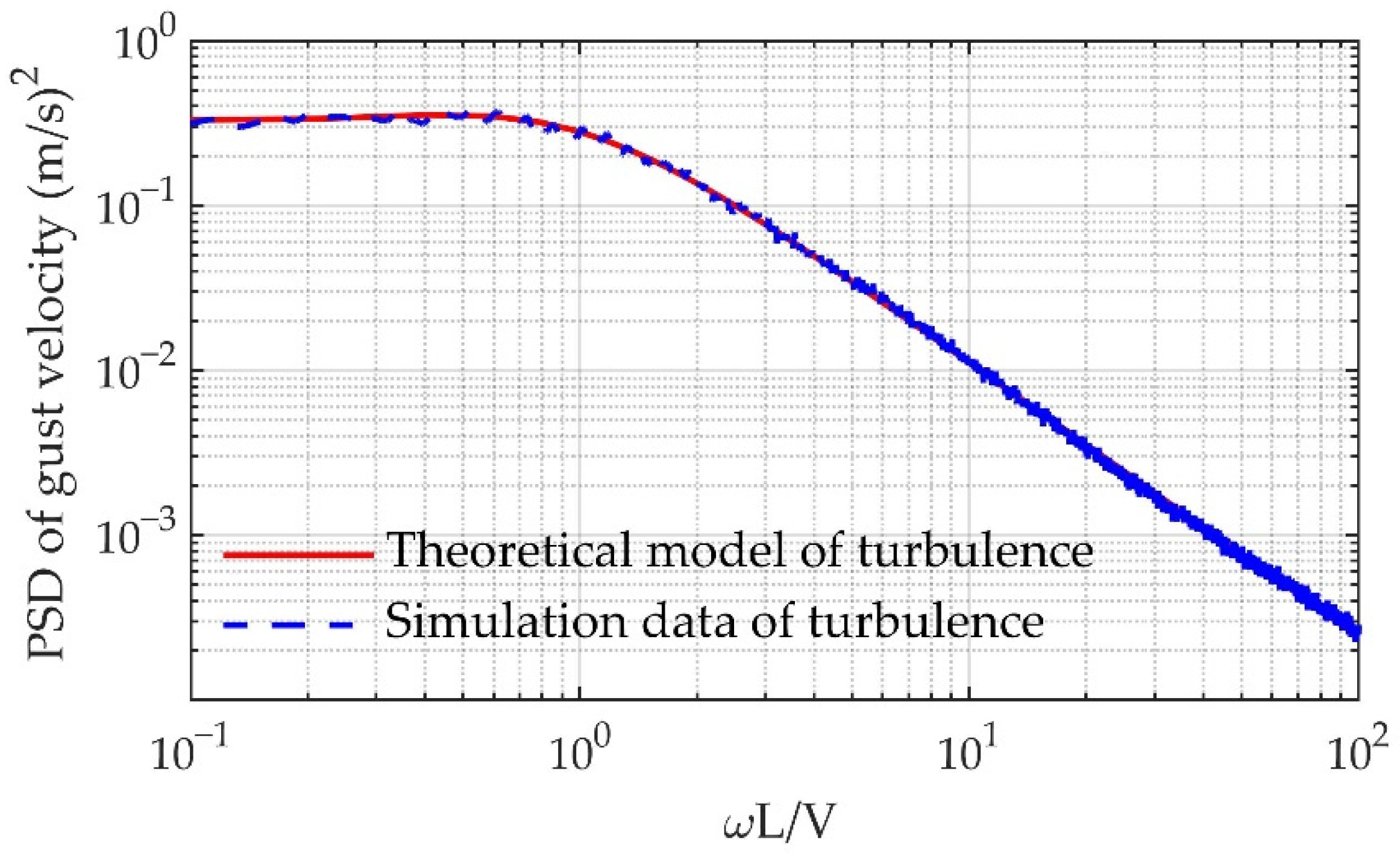
where is the conjugate transfer function of . In the simulation of present work, the Dryden turbulence model is used, and the shaping filter is defined as
where , , and the PSD of the turbulence velocity obtained by the filter is compared with the theoretical model in Figure 1.
2.4.3. Sine Gust
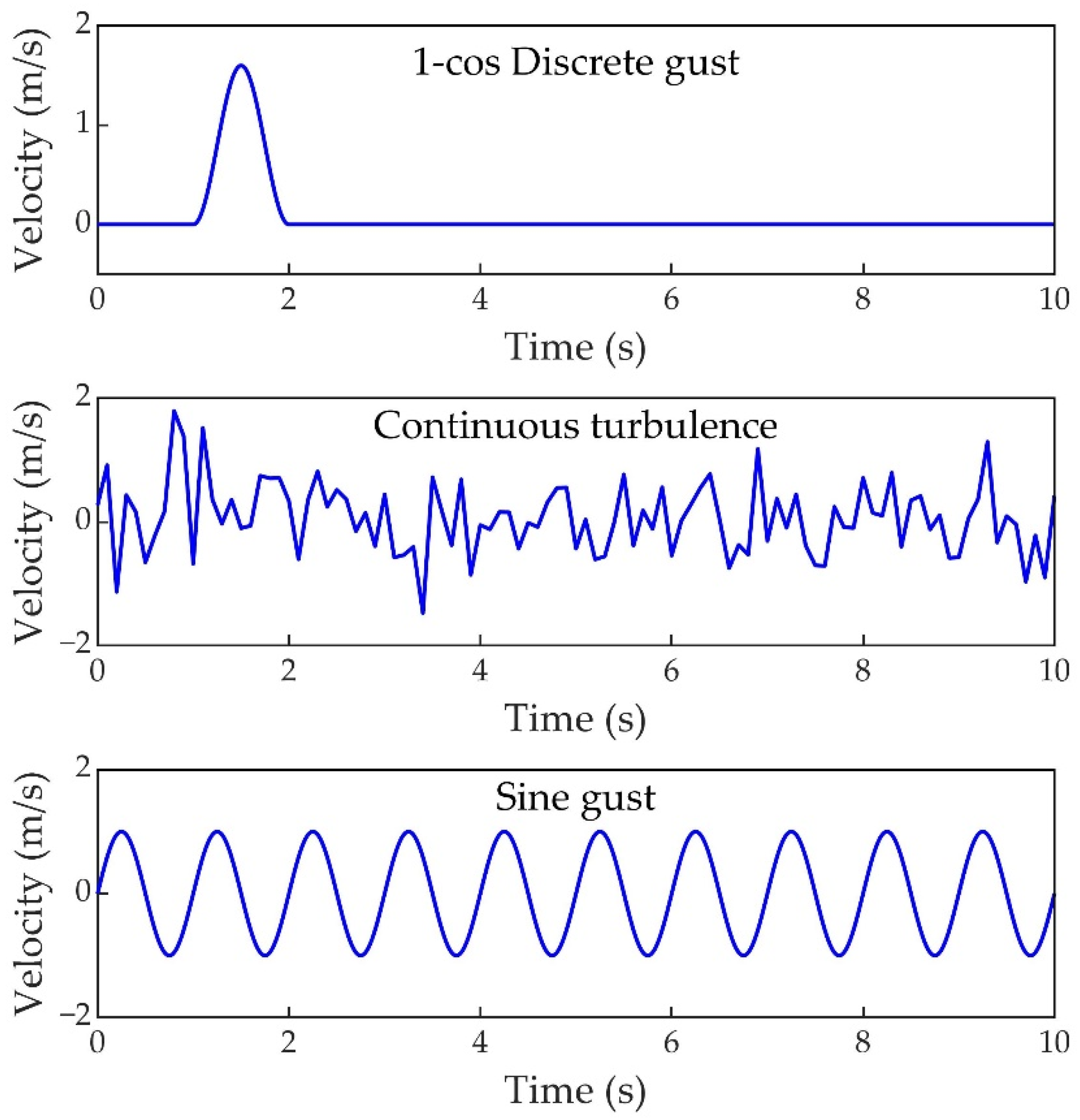
In addition, there is a gust model with fixed frequency. This kind of gust disturbance is almost non-existent in practical situations, but the gust disturbance can be generated during wind tunnel tests. It is defined by the sine function, and the mathematical expression is as follows:
where is the gust frequency. The gust velocity variation with time of 1-cos discrete gust, continuous turbulence and sine gust is shown in Figure 2.
3. Controller Design Method
3.1. Adaptive Feedforward Controller
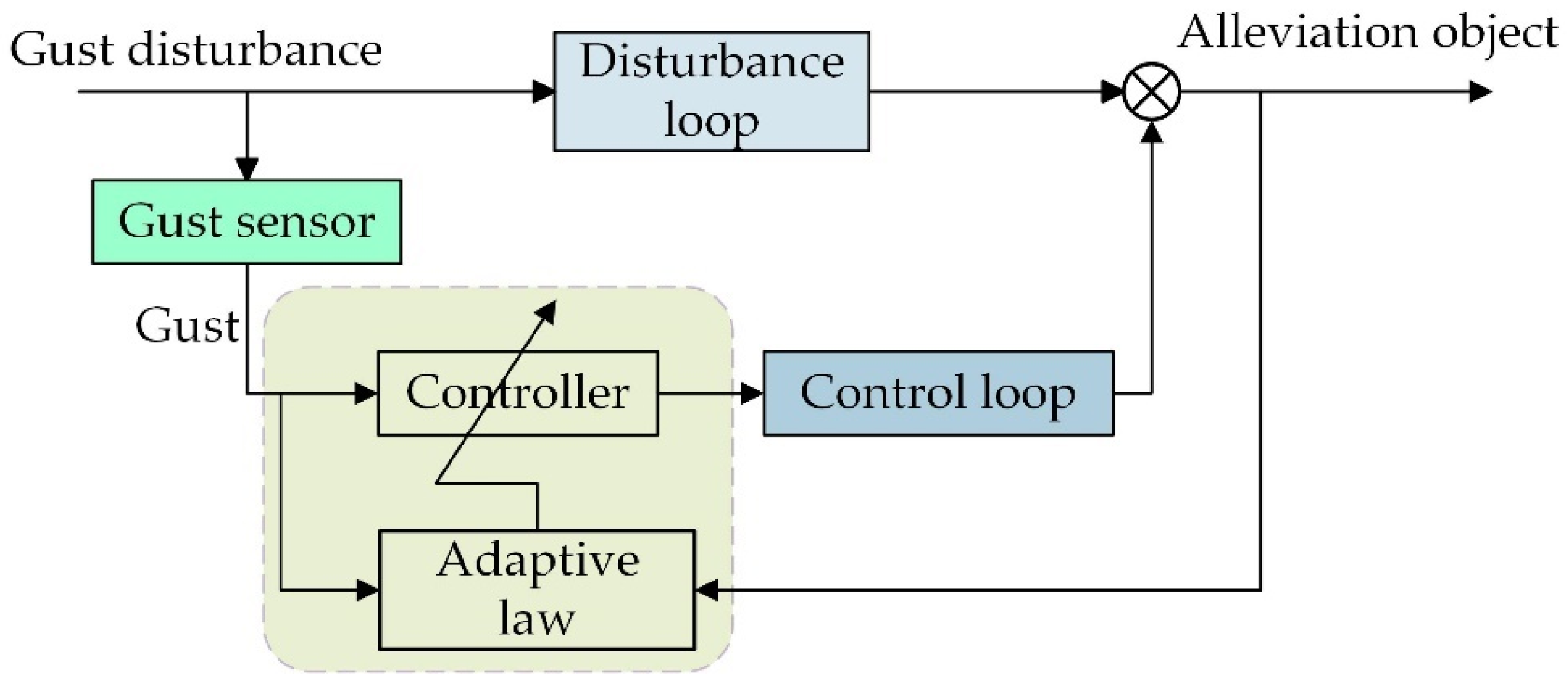
In the adaptive feedforward control, there are two loops: disturbance loop and control loop. In the disturbance loop, the dynamic response of the aircraft is generated after being disturbed by gusts; in the control loop, the FFCS takes the gust signal as the input and obtains the control command through the control law to drive the control surface deflection to offset the aerodynamic force caused by the gusts. The control system parameters are updated by adaptive law. The control principle’s block diagram is shown in Figure 3.
In the disturbance loop, the input is the gust speed , and the response caused by the gust is set to . Then, there is
where is the transfer function of gust input to the gust response output. In the control loop, the aircraft response output due to the deflection of the control surface is set to , and there is
where is the transfer function of the control system and is the transfer function of control surface to aircraft body, so in the controlled state, the total output of the aircraft is expressed as
The goal of feedforward gust alleviation is to minimize the gust response by designing a control system. In order to obtain the optimized control system, considering the aircraft gust response within a period of time and paying more attention to the latest response, the objective function can be designed as
where is the weight coefficient which less than 1. Equation (21) can also be written in discrete format [44]:
In the practical application of the sensor and control system, the signal is usually implemented in the computer in discrete format, so the FFCS will be derived in discrete format below.
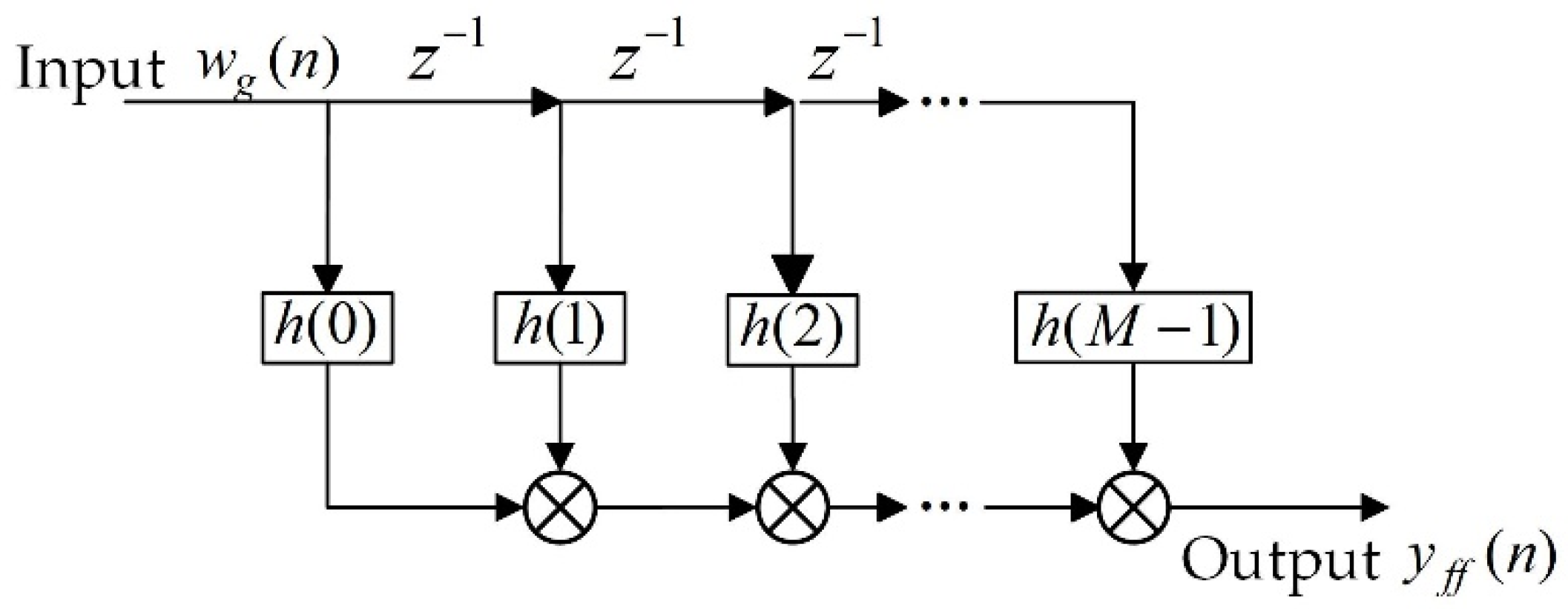
In the control loop, finite impulse response (FIR) adaptive control system is used to solve the control command. The structure of the control system is shown in Figure 4. The order of the control system is M, the input is , and the output of the control system is :
where is the weight coefficient of the control system. Obviously, in the Z domain, the poles of the control system are the origin, so no matter what value the control system parameters take, it is always stable.
For the gust alleviation problem, the control goal is to minimize the gust response. It can be seen from Equation (21) that the goal can be achieved by adjusting the optimal weight coefficient of the FIR control system. In this study, the optimal coefficients of the control system are obtained by the RLS algorithm. When the control system coefficient is optimal, the following equation holds:
where the control system weight coefficient vector is expressed as
by solving Equation (25), we can obtain
where is the weighted cross-correlation vector and can be expressed as
where is the input vector of the adaptive algorithm, the expression is
usually, the exact value of in Equation (30) is not easy to obtain, so it is often replaced by the estimated value , which is obtained through experiment or theoretical calculation. in Equation (27) is the signal inverse autocorrelation matrix. According to the inverse lemma of a matrix [44], the matrix can be obtained recursively as follows:
where is the Kalman gain vector, which is defined by
Combining Equation (27) to Equation (32), the following control system update method can be obtained as follows:
3.2. PID Feedback Controller
For the feedback control, the PID control method is used in this study. The input of the PID control system is the gust response (such as wing tip acceleration (WTA)) measured by the sensor, and the output is the control command to the control surface, which can be expressed as
where , and are the proportional coefficient, integral coefficient and differential coefficient of the control system, respectively. Generally, due to the noise influence of the measurement signal, differential control is not commonly used.
3.3. Combine Feedforward Control and Feedback Control
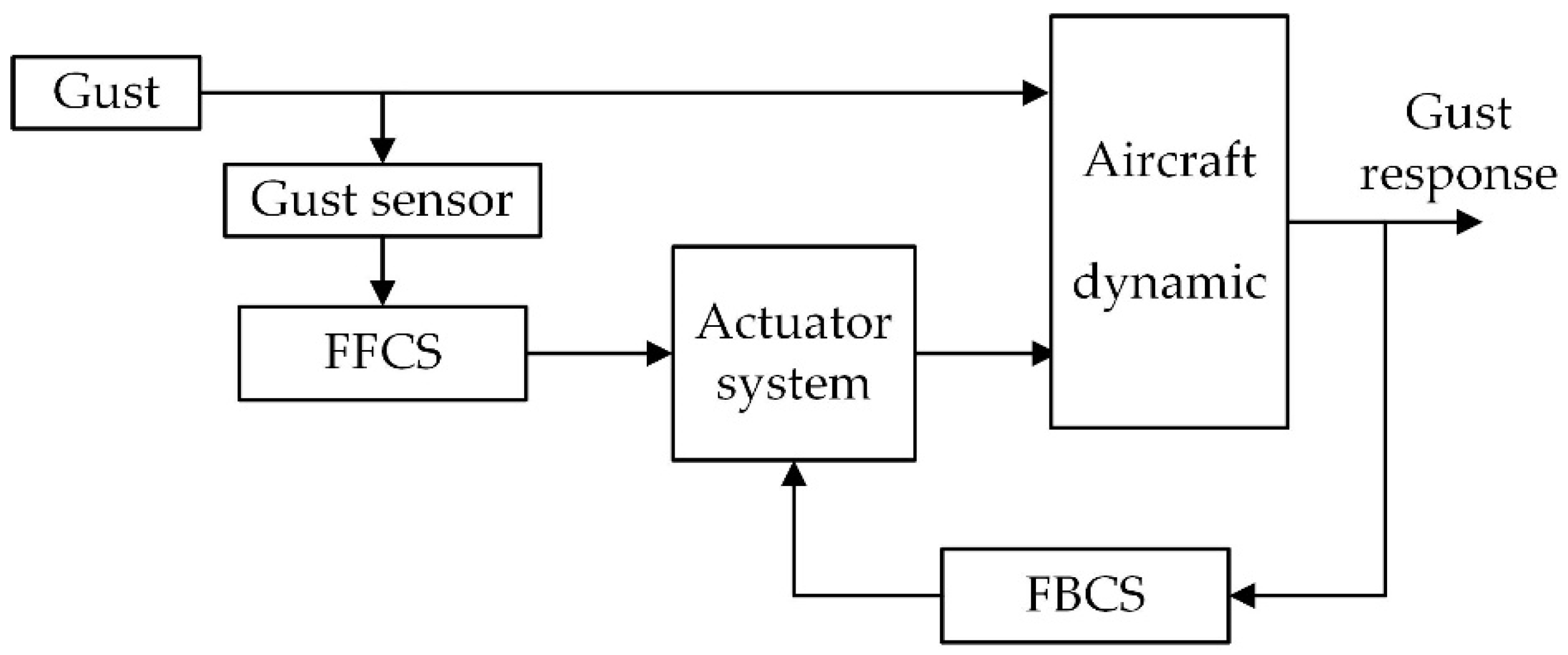
As shown in Figure 5, the CCS is composed of FFCS and FBCS. The input signal of the FFCS is the gust angle or gust velocity, and the input signal of the FBCS is the aircraft body response caused by gust excitation. The control commands of the FFCS and the FBCS can be jointly applied to the same control surface or independently applied to different control surfaces. In practical application, the deflection angle of each control surface reserved for the gust alleviation system is limited. In order to make full use of the deflection angle to obtain the best gust alleviation effect, the output commands of FFCS and FBCS can be assigned to multiple different control surfaces. For example, the FBCS uses the wing tip acceleration as the input to drive the aileron deflection to suppress the vibration of the wing, and the command of the FFCS can be applied to the elevator to suppress the rigid motion response. In short, the specific combination of the FFCS and FBCS needs to be adopted according to actual needs.
4. Numerical Simulation
4.1. Wing Model Description
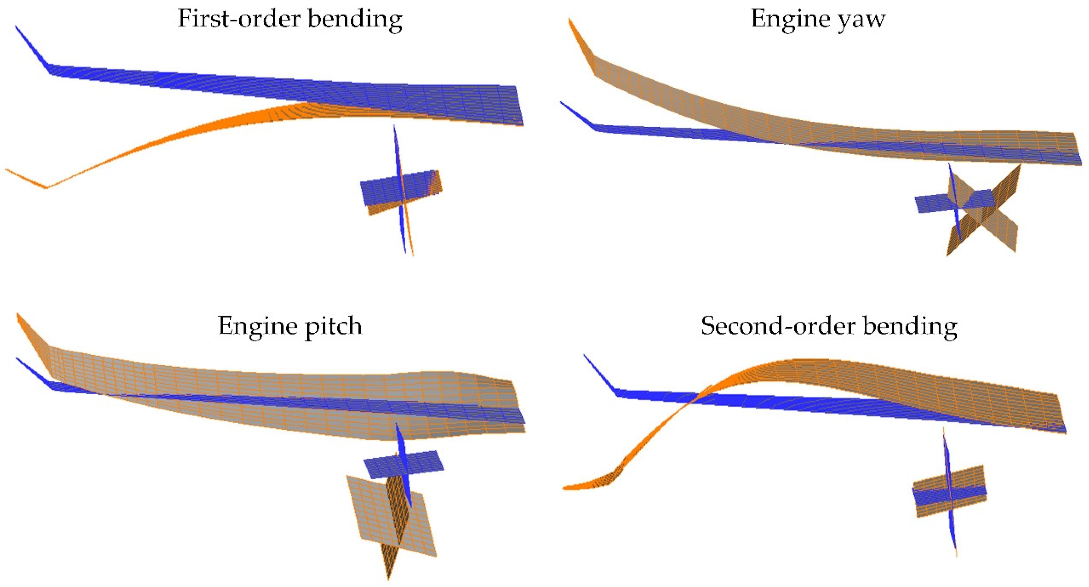
Figure 6 shows the finite element model of flexible wing equipped with an engine. There are two ailerons on the wing. All components were established by beam elements, and the mass of the model was distributed on multiple nodes in the form of lumped mass. As for the actual physical model, wing spar and ribs were made of aluminum alloy, the engine frame was made of steel, and the skin was made of glass fiber composite material. The material of the finite element model is consistent with the physical model, the stiffness characteristic of the skin is reflected by the beam element. The wingspan of model is 2.85 m, the leading-edge sweep back angle is 22.0°, and the chord length of the wing root is 0.98 m. In the simulation analysis, wing tip acceleration and wing root bending moment (WRBM) are used to evaluate gust response and alleviation rate, their location is shown in Figure 6. Before the wind tunnel test, the modal test was carried out on the physical model of the wing, and the finite element model was modified according to the test results. In this work, the double-lattice method is used to calculate the aerodynamic influence coefficient matrix in the frequency domain. Figure 7 shows the interpolated structural modes on the aerodynamic model. The comparison of the theoretical and experimental values of the first four modal frequencies is shown in Table 1.
4.2. Simulation and Results Analysis
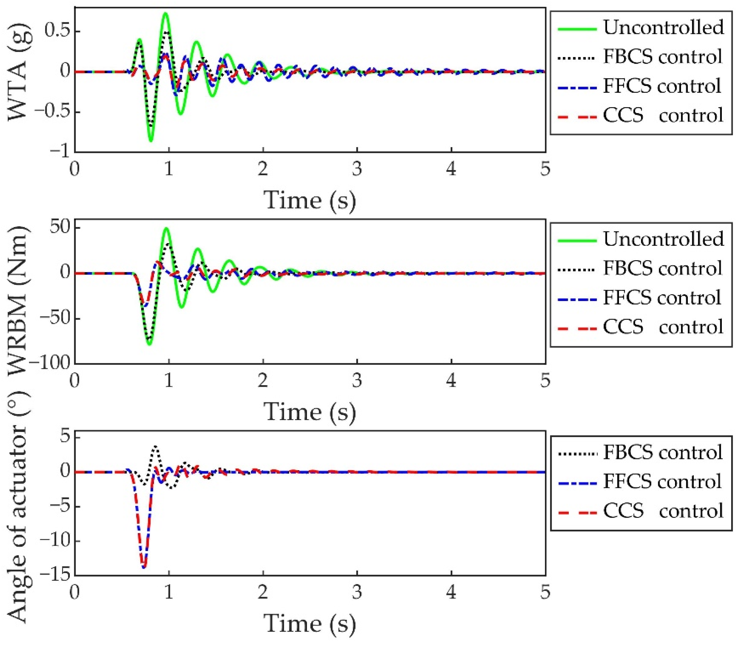
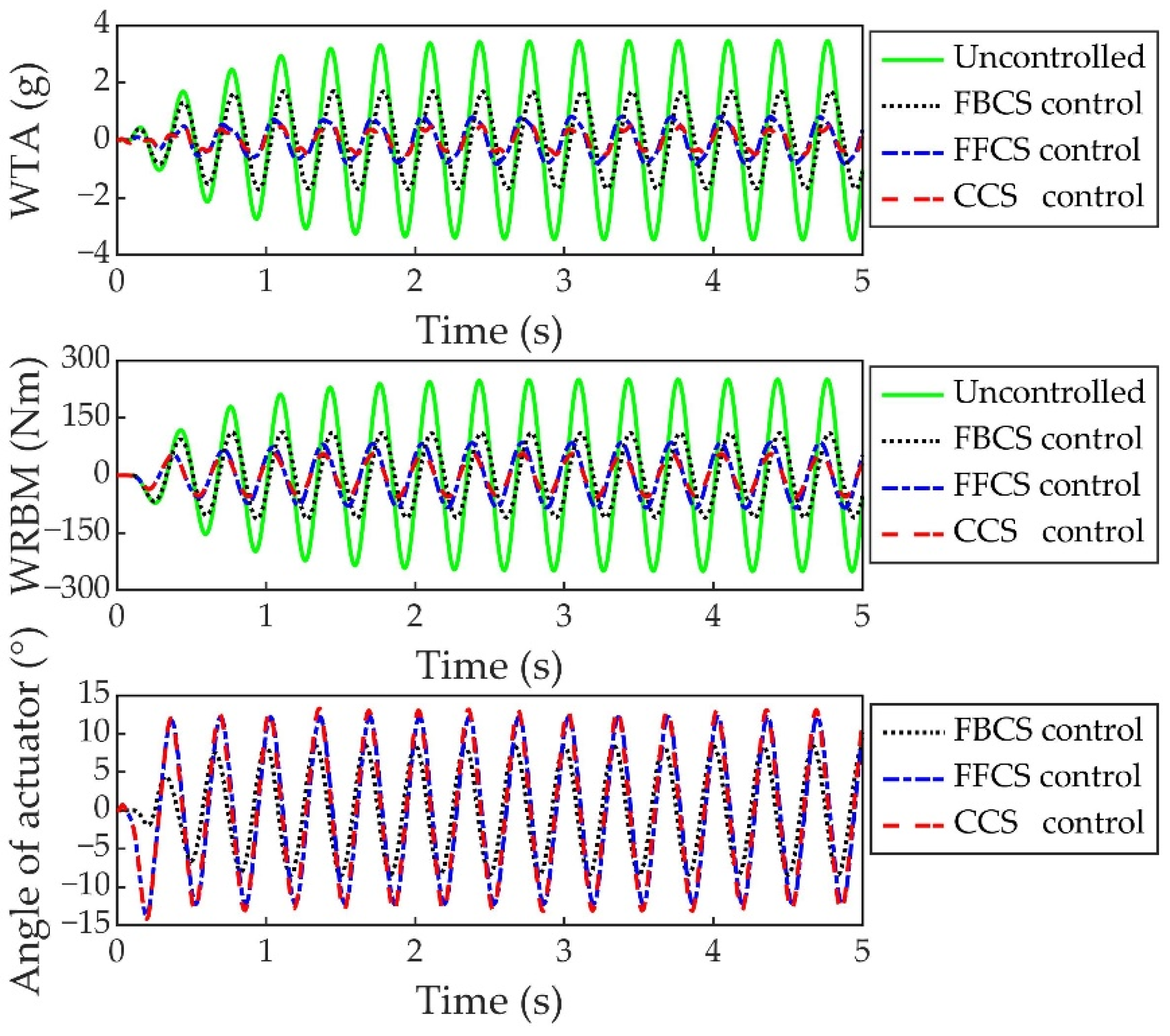
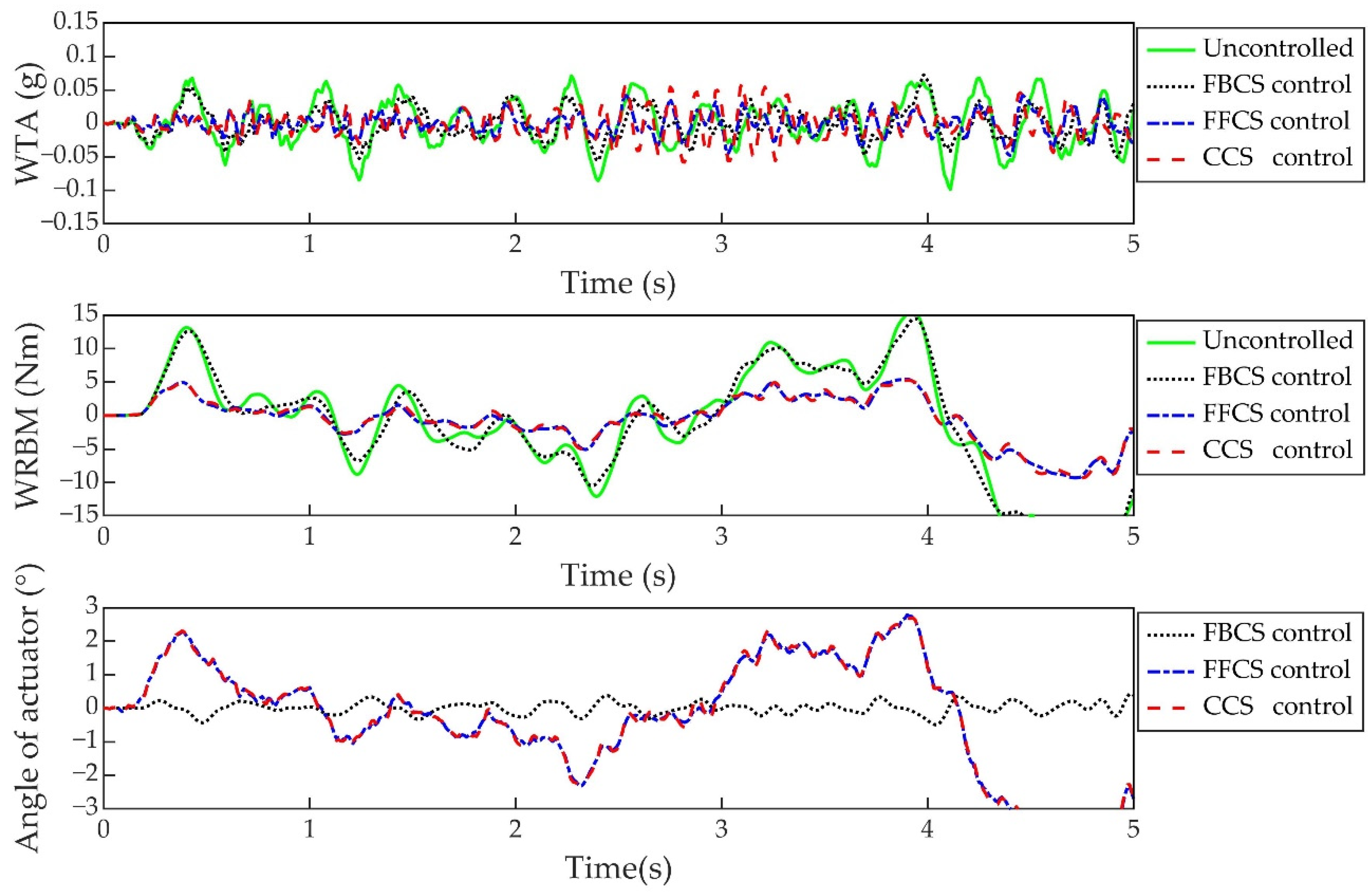
In the numerical simulation, three kinds of gusts, including continuous turbulence, 1-cos discrete gust and sine gust, are considered. The flight speed is 20.0 m/s, and the altitude is 0 km. The continuous turbulence scale is 530.0 m, and the root mean square of gust velocity is 5.0 m/s; the sine gust amplitude is 1.0 m/s and the frequency is 3.0 Hz (close to the wing’s first bending frequency 2.59 Hz); 1-cos gust amplitude is 1.0 m/s, and the gust scale is 5.0 m.
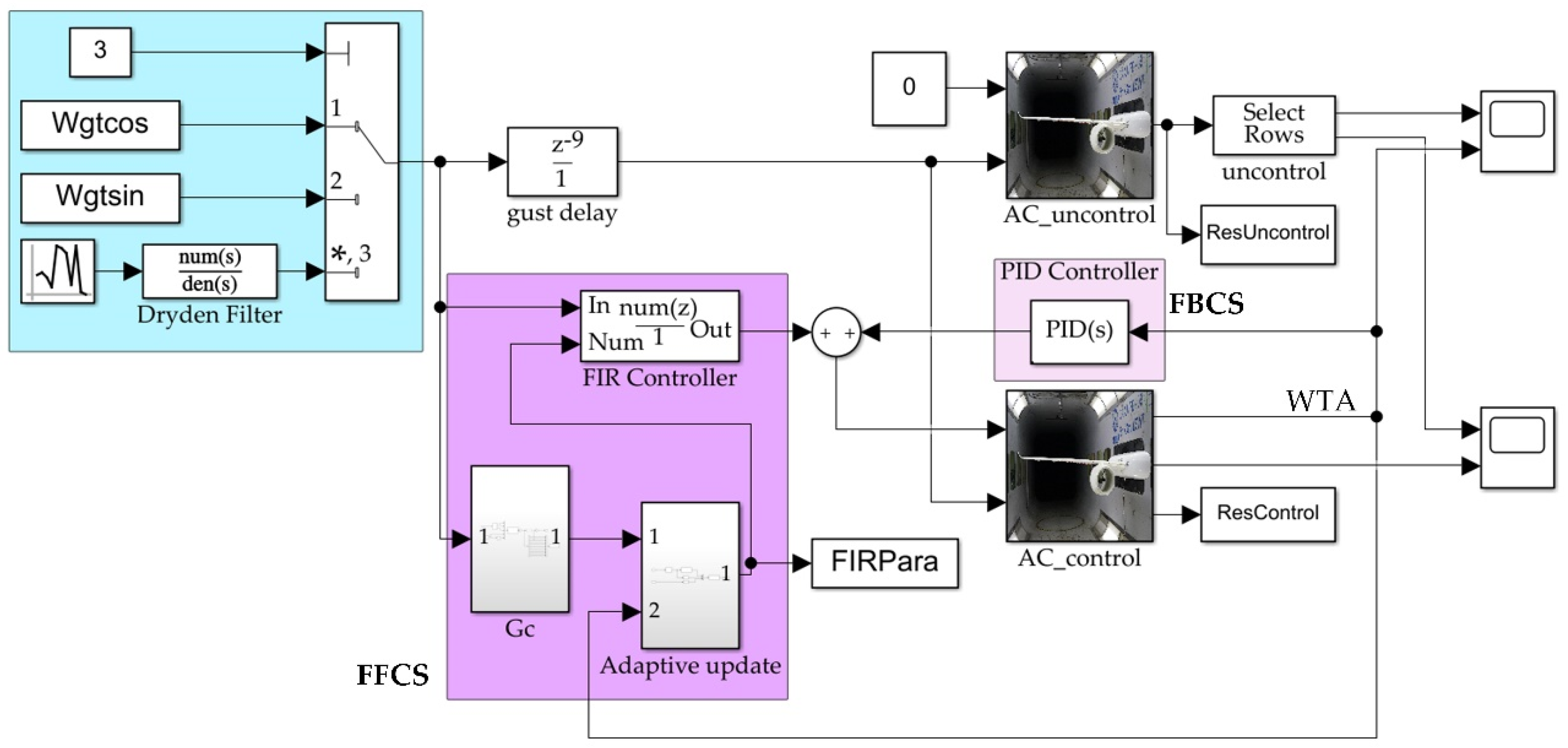
The control scheme is divided into three categories: (1) CCS, which is composed of the adaptive feedforward control system and the PID feedback control system, (2) FBCS, which is the feedback part of the CCS, (3) FFCS, which is the feedforward part of the CCS. The outer aileron is used as the control surface for all control systems. Figure 8 shows the simulation block diagram of the CCS. The gust response output signal of the wing is WTA, the adaptive block of the FFCS uses this signal as the input to update the parameters of the FIR controller, and the FBCS uses this signal as the input to calculate the feedback control signal. In terms of feedforward control, assuming that the gust signal is obtained by the ideal sensor and is used as the input of the FFCS; the gust delay module in the figure represents the time delay of the gust from gust sensor to the wing; the parameters of FFCS are updated online through the adaptive law. The FBCS is PI control. Two wing dynamics models are placed in the simulation environment for the comparison of controlled and uncontrolled gust responses.
The gust alleviation rate of the control system is defined as
where and are gust response values with control and without control, respectively. The response value is the peak value for 1-cos discrete gust and sine gust, and for turbulence, it is the root mean square value of the response.
The parameters of the FIR adaptive feedforward controller are obtained by adaptive law under continuous turbulence excitation, and the parameters of the feedback controller are determined by comprehensively considering the system stability requirements and gust alleviation effect. Figure 9, Figure 10 and Figure 11 show the comparison of the gust alleviation effects of the three control systems (CCS, FBCS, FFCS) under the excitation of 1-cos gust, sine gust and Dryden turbulence, respectively. The specific gust alleviation values are shown in Table 2. The results suggest that CCS has the best alleviation effect among all control systems. The WTA and WRBM are greatly reduced under three different forms of gust excitation. The FFCS also shows good robustness and alleviation effect. The FBCS has obvious alleviation effect on sine gust excitation with critical frequency, but the alleviation effect under continuous turbulence excitation and 1-cos gust excitation is weak, and the robustness is poor. At the same time, the alleviation effect of PI feedback control with acceleration as feedback on the bending moment is relatively poor. This is because the bending moment depends on the combined effect of aerodynamic force and inertial force, and the acceleration at the wing tip mainly represents the effect of inertial force, the FBCS mainly reduces the WRBM caused by inertial force.
5. Wind Tunnel Test Design
5.1. Test Model and Gust Generator
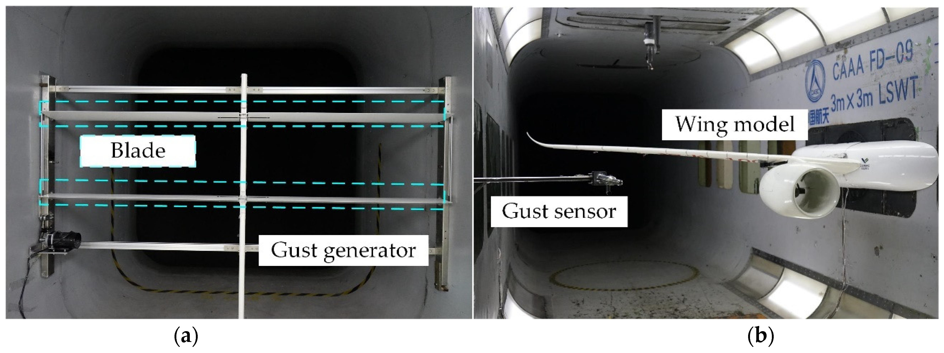
As shown in Figure 12, in the wind tunnel test, the wing model was fixed in the middle of the wind tunnel sidewall. A fairing fuselage is installed at the root of the wing, which is independent of the wing and has no effect on the stiffness of the wing. The detailed wing parameters are described in Section 4.1. The gust generator designed in the experiment is a two-stage, four-blade segmented device. The airfoil of the gust generator is NACA0015, and the chord length is 0.30 m. The span of each blade is 1.40 m. The blade deflection of the gust generator driven by a motor can produce sine gust in the wind tunnel flow field. The gust frequency range is 1.0 Hz–5.0 Hz. In the test wind speed (16.0 m/s–20.0 m/s), the gust amplitude range is 0.30 m/s–1.50 m/s. In the wind tunnel test, the gust generator is located at 5.3 m in front of the wing model, about 3.3 m away from the gust sensor. The gust alleviation test was completed in the FD-09 low-speed wind tunnel of the China Academy of Aerospace Aerodynamics.
5.2. Gust Detection
In order to carry out the feedforward gust alleviation test, it is necessary to measure the gust in the flow field as the input signal of the FFCS. When detecting gusts by using airflow angle sensors, the local airflow angle is measured by the airflow angle sensor, and the gust angle can be calculated by fusing the information measured by other sensors on the aircraft [45]:
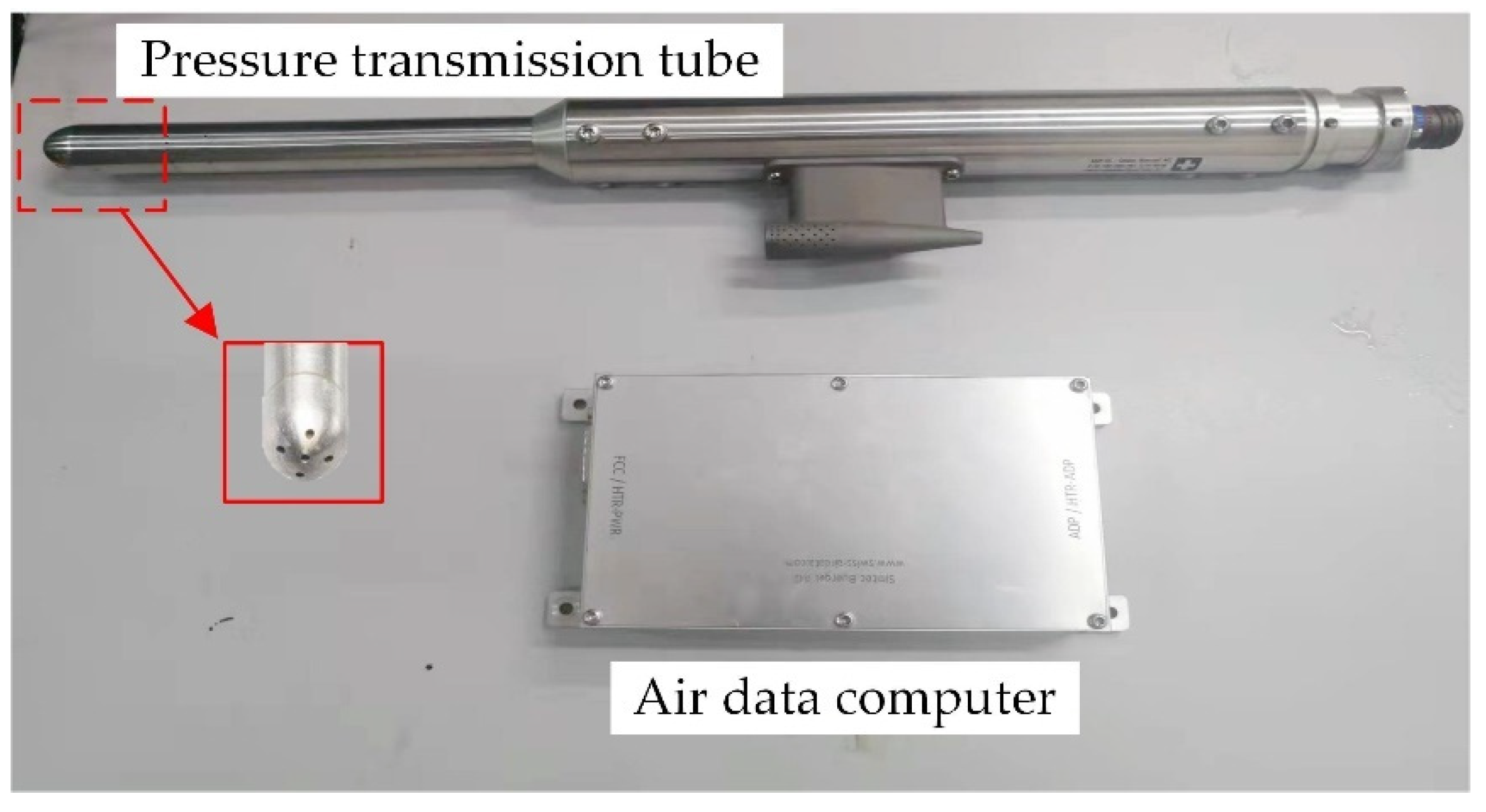
where is roll angle; is flight altitude; is pitch angle; is AOA; is AOS; is yaw angle rate; , and are the distance from the center of gravity to the AOA sensor and AOS sensor, respectively. In this study, the sensor measuring the gust angle is a five-hole probe (Figure 13) mounted on the wall of the tunnel, as shown in Figure 12. The test object is a fixed flexible wing without rigid freedom. All variables on the right of Equation (36) are zero, except , so the AOA measured by the fixed five-hole probe in the wind field is the gust angle. The five-hole probe used in the tunnel test can simultaneously measure the AOA, AOS and wind speed through the pressure difference ratio between the five holes at the head of the probe. The RS485 digital signal is output by the air data computer. The bandwidth of the five-hole probe is about 20.0 Hz, and the measurement delay is about 25.0 ms. The measurement range of AOA/AOS that can be reliably realized is from −25° to 25°.
5.3. Measurement and Control System Description
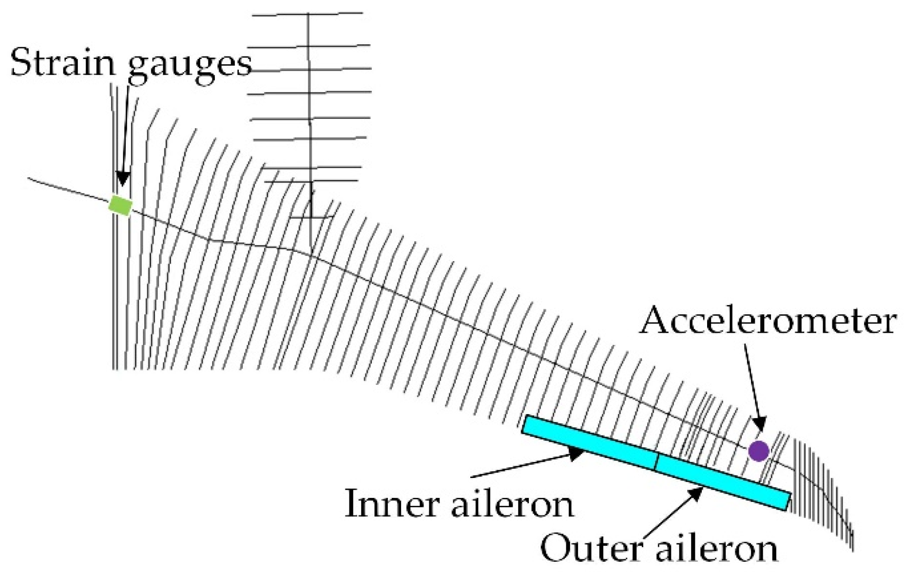
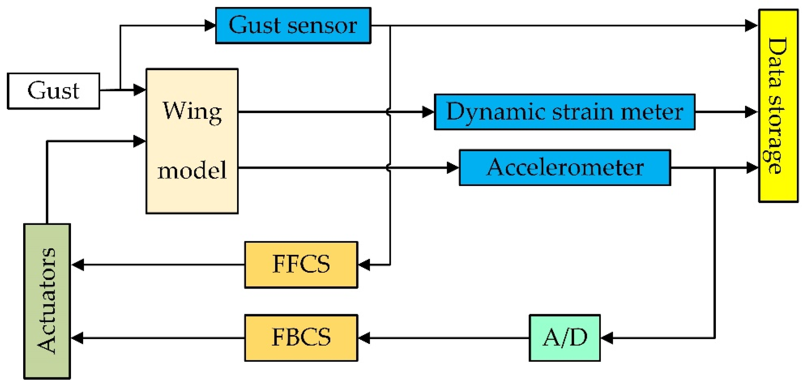
The measurement and control system of the wind tunnel test includes sensors, data acquisition equipment, control computer and actuator system. Strain gauges were pasted on the wing root to measure the WRBM. Accelerometer was installed on the wing tip to measure the WTA which is the feedback signal of the control system. Five-hole probe was used to measure the gust as the input of FFCS. The sensor signals were collected by the data acquisition equipment of the NI company and then input into the control system, in this process, PXIE-4309 was used to collect acceleration analog signal and realize the A/D conversion. The control commands obtained through the control system deflect the control surfaces to achieve gust alleviation. The actuator is the FUTABA brushless digital actuator. The speed of the actuator is 0.12 s/60°, the delay is about 100 ms, and the maximum torque is about 7.40 Nm. The structure of the measurement and control system is shown in Figure 14.
When implementing the wind tunnel test, for the sake of simplicity, the feedback control adopts PI control, and the control law is
where is the FBCS output; is the proportional coefficient; is the integral coefficient; and is the WTA. The FFCS is simplified to a first-order control system, and its control form is as follows:
where is the output of the FFCS; is the control system gain; is the transform operator; is the delay parameter whose value depends on the wind speed and delay of the test hardware; and is the gust angle.
6. Wind Tunnel Results and Discussion
6.1. Comparison between Experiment and Numerical Simulation
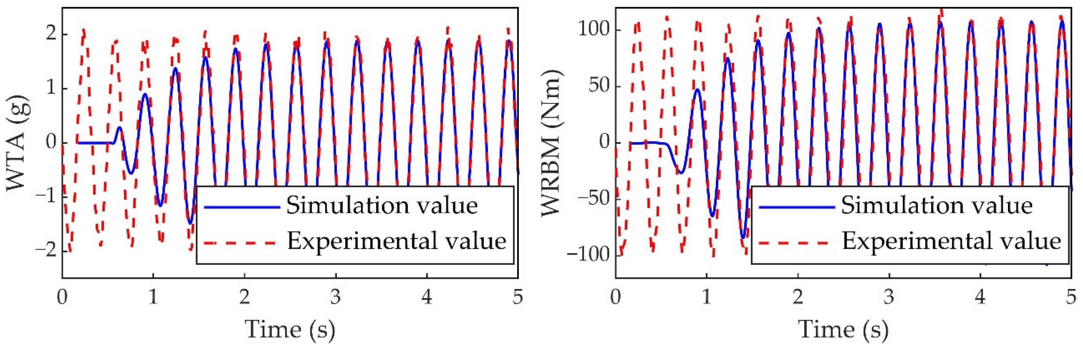
When the flight speed is 20.0 m/s, without control, the comparison between the experimental and simulation results (WTA and WRBM) under 3.0 Hz gust excitation is shown in Figure 15. The gust velocity used in the simulation is the experimental value. It can be seen from the figure that the simulation value is in good agreement with the experimental value. For the controlled situation, only the outer aileron is used as the control surface. The comparison between the experimental value and the simulation value of the alleviation rate of feedforward control and feedback control is shown in Table 3. It can be found that the experimental alleviation rate of the feedback control is close to the simulation value, but the simulation alleviation rate of the feedforward control is quite different from the experimental value. This is mainly because the delay of each hardware in the experiment cannot be accurately measured, so it cannot be accurately simulated in the numerical simulation, and the effect of the FFCS is affected by the delay time of the hardware.
6.2. Wind Tunnel Test Results at Different Wind Speeds and Key Frequency
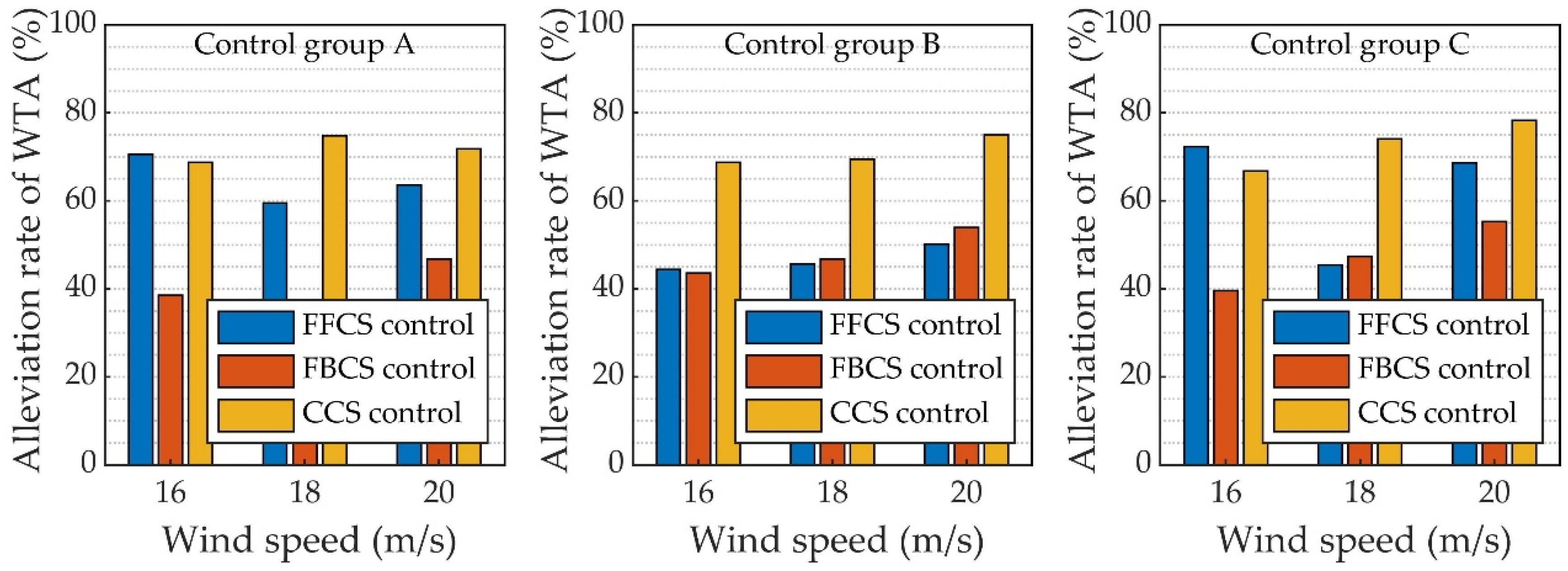
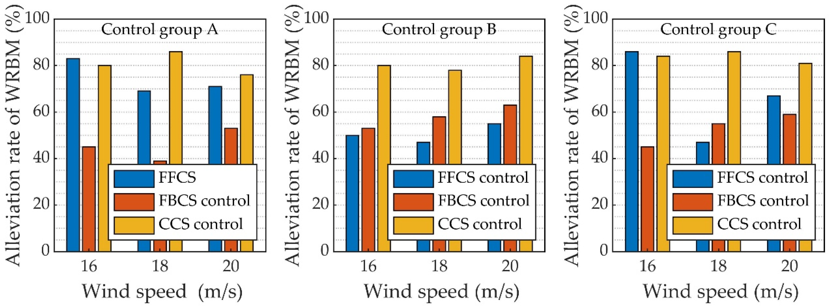
In the wind tunnel test, three group control schemes are designed according to the different control surface selections: (1) control group A: the control system (CCS or FFCS or FBCS) drives the inner and outer aileron together, and the two control surfaces deflect the same angle at any time; (2) control group B: the FFCS drives the inner aileron, and the FBCS drives the outer aileron. For the CCS, the inner and outer aileron deflect independently at the same time; (3) control group C: the FBCS drives the inner aileron, the FFCS drives the outer aileron, and the inner and outer control surfaces are deflected independently during the combined control.
For the above three group control schemes, gust alleviation tests were carried out under three different wind speeds (16.0 m/s, 18.0 m/s and 20.0 m/s), the frequency of the gust generator was fixed at 3.0 Hz, and the gust response under this excitation frequency is larger. It should be noted that in the same group, the control parameters of the FBCS remain unchanged under different wind speeds, and the delay parameters of the FFCS are adjusted with different wind speeds. Figure 16 and Figure 17 are the comparison of the alleviation rate of WAT and WRBM, respectively. It can be seen from the figure that, no matter which control scheme is adopted, the CCS is more likely to achieve higher gust alleviation rate, and for different wind speeds, the alleviation rate of WRBM can reach about 80%, while the alleviation rate of WTA can reach about 70%. Compared with FFCS and FBCS, FFCS achieves good gust alleviation effect more easily because the feedforward control belongs to the open-loop control mode, and the control parameters have no effect on the stability of the wing aeroservoelastic system, so it can take a relatively large control gain to achieve gust alleviation, and the control parameters of the FBCS directly affect the stability of the closed-loop aeroelastic system. The control system gain selected cannot be too large due to the requirements of system stability, so smaller gain affects the gust alleviation effect of the FBCS.
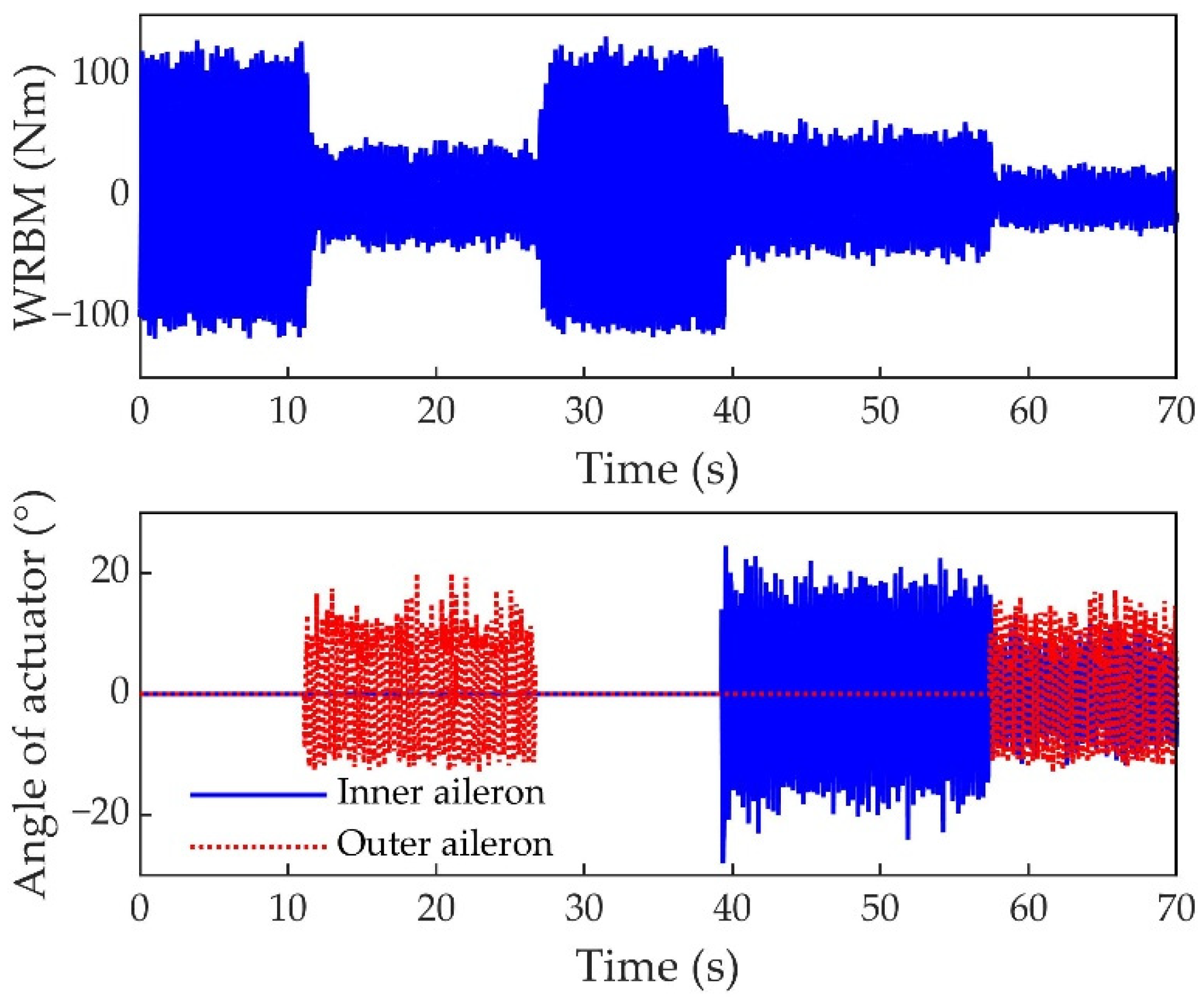
Figure 18 shows the time domain response curves of the WRBM and the deflection angles of the two control surfaces in the wind tunnel test of control group C at wind speed of 20.0 m/s. The wing is in an uncontrolled state from 0 s to 12 s; from 12 s to 28 s, the FFCS drives the outer control surface deflection to achieve gust alleviation; from 28 s to 40 s, the wing is in uncontrolled state again; from 40 s to 58 s, the FBCS drives the inner control surface deflection; 58 s to 70 s is the combined control stage, FFCS and FBCS are simultaneously activated to drive the deflection of the inner and outer control surfaces. It can be clearly seen from the figure that the WRBM is reduced to varying degrees under the action of the different control systems.
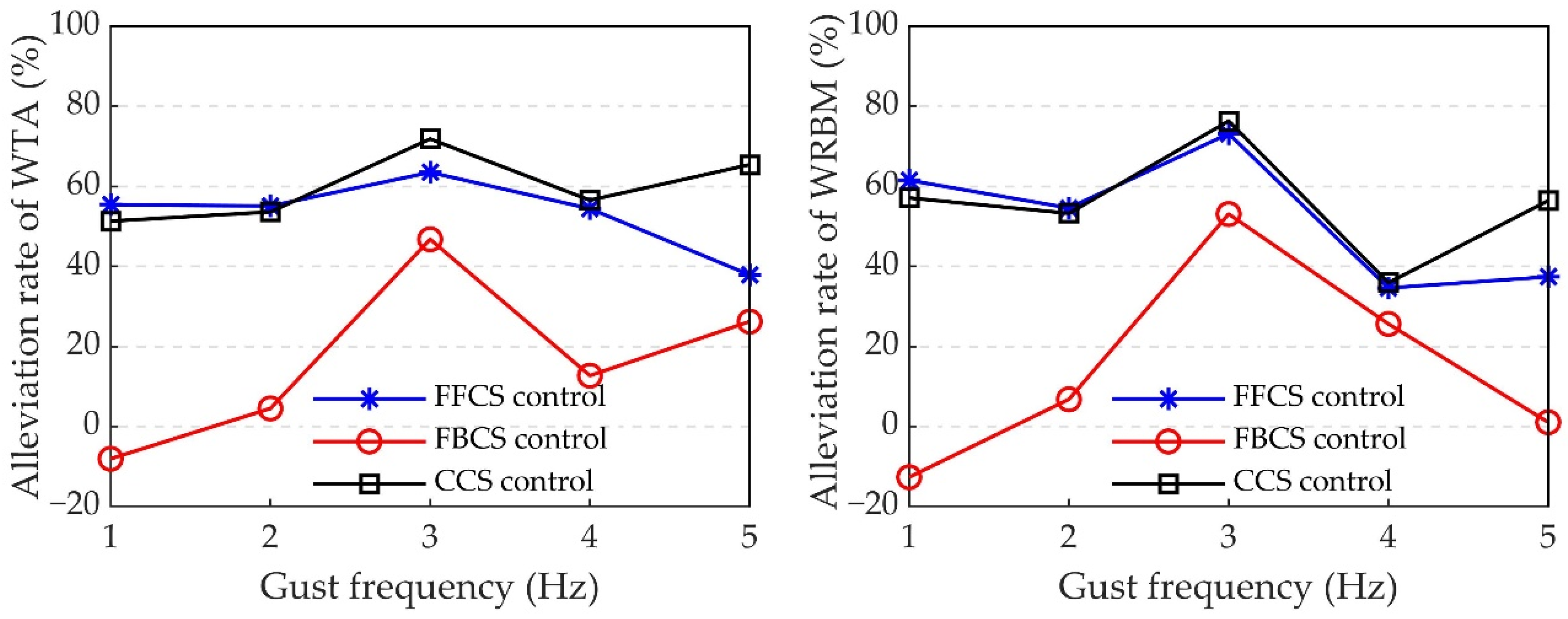
6.3. Wind Tunnel Test Results with The Same Wind Speed and Different Gust Frequencies
At wind speed of 20.0 m/s, gust frequency varies from 1.0 Hz to 5.0 Hz, and all control system parameters remain unchanged under different test conditions. Figure 19 shows the alleviation effect of each control system in control group A under gust excitation of different frequencies. It can be seen from the figure that the alleviation effect of FFCS, FBCS and CCS are good when the gust frequency is 3.0 Hz. FFCS at other frequencies still has more than 40% alleviation rate, and the robustness is good; the alleviation rate of FBCS at other gust frequencies are greatly reduced and the robustness is poor. In general, the alleviation effect of CCS combining feedforward and feedback control is the best.
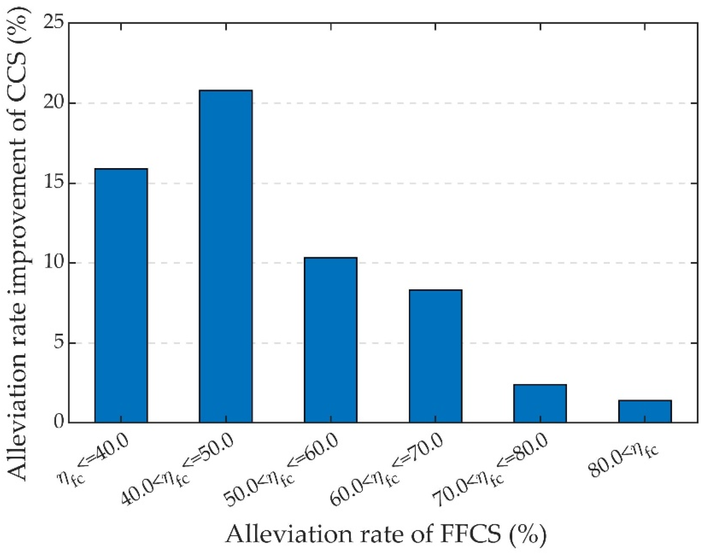
6.4. Improvement of Alleviation Rate by Combining Feedforward and Feedback Control
On the basis of FFCS, if the FBCS to be added to form the CCS, the improvement of gust alleviation rate will not always be ideal. After adding feedback control on the basis of feedforward control, the improvement of the alleviation rate of CCS is defined as
where is the alleviation rate of CCS and is the alleviation rate of FFCS.
All alleviation rate data of FFCS and CCS involved in the simulation and experiment in this paper are counted and compared. It can be found from Figure 20 that when the alleviation rate of the FFCS is low (for example, when there is only feedforward control, the alleviation rate is less than 50%), the alleviation rate can be effectively improved by adding the FBCS. If the alleviation rate of feedforward control is higher, it becomes more and more difficult to increase the control effect by adding feedback control on the FFCS. The reason for this phenomenon is that if the gust response of the wing has been effectively suppressed under the control of the FFCS, the control command signal that can be output by the FBCS using the gust response signal as the input will become smaller, so further improvement of the gust alleviation rate is relatively limited.
7. Conclusions
This study shows the process of gust alleviation by combining feedforward control and feedback control, taking a fixed supported flexible wing as research object, numerical simulation and wind tunnel test was carried out. Some conclusions can be obtained as follows: (1) Numerical simulation and wind tunnel test show that the CCS is more likely to achieve good gust alleviation effect. For example, the wind tunnel test results show that under CCS control, for different wind speeds and 3 Hz gust excitation, WRBM and WTA can be reduced by nearly 80% and 70%, respectively. (2) Compared with feedback control, feedforward control has better robustness and achieves good gust alleviation effect more easily. The selection of the parameters of FBCS is limited by the system stability requirement, which makes it difficult to obtain higher control effect. (3) Compared with single feedforward control, the improvement of the gust alleviation effect by adding feedback control is related to the original effect of FFCS, that is, the better the effect of FFCS, the more difficult it is to improve the control performance by adding feedback control. (4) The wind tunnel test results demonstrated that the gust detection method based on a five-hole probe still has good alleviation effect when the gust frequency is high (5.0 Hz), while the natural gust is dominated by low-frequency components, which indicates that the five-hole probe can be used to carry out the practical application of feedforward gust alleviation.
The research object of this paper is the fixed supported flexible wing without rigid body freedom. The gust response (WTA, WRBM, etc.) is mainly dominated by the flexible mode. In future research work, theoretical and experimental research on the complex full-aircraft model with rigid degrees of freedom will be further carried out.
Author Contributions
Conceptualization, Z.W.; methodology, Z.W. and Y.Z.; software, Y.Z.; validation, Z.W. and Y.Z.; formal analysis, Y.Z.; writing—original draft preparation, Y.Z.; writing—review and editing, Z.W.; supervision, C.Y.; project administration, C.Y. All authors have read and agreed to the published version of the manuscript.
Funding
This research received no external funding.
Institutional Review Board Statement
Not applicable.
Informed Consent Statement
Not applicable.
Data Availability Statement
Not applicable.
Conflicts of Interest
The authors declare no conflict of interest.
Nomenclature
| Gust response value with control | Gust response value without control | ||
| Damping matrix | Fitting polynomial coefficient matrix | ||
| Weighted cross-correlation vector | Fitting polynomial coefficient matrix | ||
| Gust frequency | Internal force | ||
| Transfer function from control surface deflection angle to aircraft | Gust shaping filter | ||
| Transfer function of control system | Control system weight coefficient vector | ||
| Objective function | Element stiffness matrix | ||
| Stiffness matrix | Control system gain | ||
| Kalman gain vector | Reduced frequency | ||
| Gust scale | Mass matrix | ||
| Inverse autocorrelation matrix | Generalized aerodynamic matrix | ||
| Yaw angle rate | Lag root coefficient matrix | ||
| Laplace variable | Input vector of the adaptive algorithm | ||
| Flight speed | Gusts velocity | ||
| Gust amplitude | Aerodynamic state function | ||
| State vector | Distance from center of gravity to AOA sensor | ||
| Distance from center of gravity to AOS sensor | Response caused by control system | ||
| Response caused by gust | Transform operator | ||
| Gust angle | Angle of attack | ||
| Angle of sideslip | Control surface deflection angle | ||
| Alleviation rate | Pitch angle | ||
| Weight coefficient | Air density | ||
| Roll angle | PSD of gust | ||
| Modal vector |
Abbreviations
| AOA | Angle of attack |
| AOS | Angle of sideslip |
| CCS | Combined control system |
| CCLMS | Circular leaky least mean square |
| GAS | Gust alleviation system |
| FBCS | Feedback control system |
| FFCS | Feedforward control system |
| FIR | Finite impulse response |
| LMS | Least mean square |
| LIDAR | Light detection and ranging |
| RLS | Recursive least square |
| WRBM | Wing root bending moment |
| WTA | Wing tip acceleration |
References
- Katnam, K.B.; Da Silva, L.F.M.; Young, T.M. Bonded repair of composite aircraft structures: A review of scientific challenges and opportunities. Prog. Aeosp. Sci. 2013, 61, 26–42. [Google Scholar] [CrossRef]
- Alam, M.; Hromcik, M.; Hanis, T. Active gust load alleviation system for flexible aircraft: Mixed feedforward/feedback approach. Aerosp. Sci. Technol. 2015, 41, 122–133. [Google Scholar] [CrossRef]
- Wu, Z.; Chen, L.; Yang, C.; Tang, C. Gust response modeling and alleviation scheme design for an elastic aircraft. Sci. China-Technol. Sci. 2010, 53, 3110–3118. [Google Scholar] [CrossRef]
- Karpel, M. Design for active flutter suppression and gust alleviation using state-space aeroelastic modeling. J. Aircr. 1982, 19, 221–227. [Google Scholar] [CrossRef]
- Liebst, B.S.; Garrard, W.L.; Farm, J.A. Design of a multivariable flutter suppression/gust load alleviation system. J. Guid. Control Dyn. 1988, 11, 220–229. [Google Scholar] [CrossRef]
- Dillsaver, M.J.; Cesnik, C.E.S.; Kolmanovsky, I.V. Gust load alleviation control for very flexible aircraft. In Proceedings of the AIAA Atmospheric Flight Mechanics Conference 2011, Portland, OR, USA, 8–11 August 2011. [Google Scholar] [CrossRef] [Green Version]
- Liu, X.; Sun, Q. Improved LQG method for active gust load alleviation. J. Aerosp. Eng. 2017, 30. [Google Scholar] [CrossRef]
- Zhang, J.; Li, Z.; Zhan, M.; Gao, Y. Application of LQG theory to gust load alleviation system. Flight Dyn. 2007, 61–64. [Google Scholar] [CrossRef]
- Cook, R.G.; Palacios, R.; Goulart, P. Robust gust alleviation and stabilization of very flexible aircraft. AIAA J. 2013, 51, 330–340. [Google Scholar] [CrossRef]
- Aouf, N.; Boulet, B.; Botez, R.M. Robust gust load alleviation for a flexible aircraft. Can. Aeronaut. Space J. 2000, 46, 131–139. [Google Scholar]
- Fu, J.; Wan, J.; Ai, J. Robust control of flexible aircraft for gust alleviation. Fudan J. 2016, 55, 329–335. [Google Scholar] [CrossRef]
- Haghighat, S.; Liu, H.H.T.; Martins, J.R.R.A. Model-predictive gust load alleviation controller for a highly flexible aircraft. J. Guid. Control Dyn. 2012, 35, 1751–1766. [Google Scholar] [CrossRef]
- Liu, J.; Hu, Z.; Zhang, W.; Xu, L.; He, Q. A MPC and control allocation method for gust load alleviation. J. Northwest. Polytech. Univ. 2017, 35, 259–266. [Google Scholar] [CrossRef]
- Liu, X.; Sun, Q.; Cooper, J.E. LQG based model predictive control for gust load alleviation. Aerosp. Sci. Technol. 2017, 71, 499–509. [Google Scholar] [CrossRef] [Green Version]
- Shao, K.; Wu, Z.; Yang, C.; Chen, L. Theoretical and experimental study of gust response alleviation using neuro-fuzzy control law for a flexible wing model. Chin. J. Aeronaut. 2010, 23, 290–297. [Google Scholar] [CrossRef]
- Shao, K.; Yang, C.; Wu, Z.; H, L.; B, W. Design of a gust-response-alleviation online control system based on neuro-fuzzy theory. J. Aircr. 2013, 50, 599–609. [Google Scholar] [CrossRef]
- Wu, Z.; Chen, L.; Yang, C. Study on gust alleviation control and wind tunnel test. Sci. China-Technol. Sci. 2013, 56, 762–771. [Google Scholar] [CrossRef]
- Matsuzaki, Y.; Ueda, T.; Miyazawa, Y.; Matsushita, H. Gust load alleviation of a transport-type wing: Test and analysis. J. Aircr. 1989, 26, 322–327. [Google Scholar] [CrossRef]
- Scott, R.C.; Castelluccio, M.A.; Coulson, D.A.; Heeg, J. Aeroservoelastic wind-tunnel tests of a free-flying, Joined-Wing SensorCraft model for gust load alleviation. In Proceedings of the 52nd AIAA/ASME/ASCE/AHS/ASC Structures, Structural Dynamics and Materials Conference, Denver, CO, USA, 4–7 April 2011; p. 1960. [Google Scholar] [CrossRef] [Green Version]
- Yang, J.; Wu, Z.; Dai, Y.; Ma, C.; Yang, C. Wind tunnel test of gust alleviation active control for flying wing configuration aircraft. J. Beijing Univ. Aeronaut. Astronaut. 2017, 43, 184–192. [Google Scholar] [CrossRef]
- Disney, T.E. C-5A active load alleviation system. J. Spacecr. Rocket. 1977, 14, 81–86. [Google Scholar] [CrossRef]
- Johnston, J.; Urie, D. Development and flight evaluation of active controls in the L-1011. In Proceedings of the Proceedings of CTOL Transport Technology Conference, Hampton, VA, USA, 28 February–3 March 1978; pp. 647–685. [Google Scholar]
- Britt, R.T.; Jacobson, S.B.; Arthurs, T.D. Aeroservoelastic analysis of the B-2 bomber. J. Aircr. 2000, 37, 745–752. [Google Scholar] [CrossRef]
- Regan, C.D.; Jutte, C.V. Survey of Applications of Active Control Technology for Gust Alleviation and New Challenges for Lighter-Weight Aircraft; NASA/TM-2012-216008; NASA—Dryden Flight Research Center: Edwards, CA, USA, 2012.
- Schmitt, N.P.; Rehm, W.; Pistner, T.; Zeller, P.; Diehl, H.; Navé, P. The AWIATOR airborne LIDAR turbulence sensor. Aerosp. Sci. Technol. 2007, 11, 546–552. [Google Scholar] [CrossRef]
- Wildschek, A.; Maier, R.; Hahn, K.-U.; Leissling, D.; Preß, M.; Zach, A. Flight test with an adaptive feed-forward controller for alleviation of turbulence excited wing bending vibrations. In Proceedings of the AIAA Guidance, Navigation, and Control Conference, Chicago, IL, USA, 10–13 August 2009; p. 6118. [Google Scholar] [CrossRef]
- Wildschek, A.; Maier, R.; Hoffmann, F.; Jeanneau, M.; Baier, H. Active wing load alleviation with an adaptive feed-forward control algorithm. In Proceedings of the AIAA Guidance, Navigation, and Control Conference and Exhibit, Keystone, CO, USA, 21–24 August 2006; p. 6054. [Google Scholar] [CrossRef]
- Zhao, Y.; Yue, C.; Hu, H. Gust load alleviation on a large transport airplane. J. Aircr. 2016, 53, 1932–1946. [Google Scholar] [CrossRef]
- Zeng, J.; Moulin, B.; de Callafon, R.; Brenner, M.J. Adaptive feedforward control for gust load alleviation. J. Guid. Control Dyn. 2010, 33, 862–872. [Google Scholar] [CrossRef]
- Fournier, H.; Massioni, P.; Pham, M.T.; Bako, L.; Vernay, R.; Colombo, M. Robust gust load alleviation of flexible aircraft equipped with lidar. J. Guid. Control Dyn. 2022, 45, 58–72. [Google Scholar] [CrossRef]
- Hamada, Y. Flight test results of disturbance attenuation using preview feedforward compensation. IFAC-PapersOnLine 2017, 50, 14188–14193. [Google Scholar] [CrossRef]
- Li, F.; Wang, Y.; Ronch, A.D. Flight testing adaptive feedback/feedforward controller for gust loads alleviation on a flexible aircraft. In Proceedings of the AIAA Atmospheric Flight Mechanics Conference, Washington, DC, USA, 13–17 June 2016; p. 3100. [Google Scholar] [CrossRef]
- Wildschek, A.; Maier, R.; Hoffmann, F.; Steigenberger, J.; Kaulfuss, K.-H.; Breitsamter, C.; Allen, A.; Adams, N.; Baier, H.; Giannopoulos, T. Wind tunnel testing of an adaptive control system for vibration suppression on aircraft. In Proceedings of the AIAA Guidance, Navigation and Control Conference and Exhibit, Hilton Head, SC, USA, 20–23 August 2007; p. 6331. [Google Scholar] [CrossRef]
- Hamada, Y.; Saitoh, K.; Kobiki, N. Gust alleviation control using prior gust information: Wind tunnel test results. Ifac Pap. 2019, 52, 128–133. [Google Scholar] [CrossRef]
- Karpel, M.; Moulin, B.; Chen, P.C. Dynamic response of aeroservoelastic systems to gust excitation. J. Aircr. 2005, 42, 1264–1272. [Google Scholar] [CrossRef]
- Karpel, M. Time-domain aeroservoelastic modeling using weighted unsteady aerodynamic forces. J. Guid. Control Dyn. 1990, 13, 30–37. [Google Scholar] [CrossRef]
- Moulin, B.; Karpel, M. Gust loads alleviation using special control surfaces. J. Aircr. 2007, 44, 17–25. [Google Scholar] [CrossRef]
- Rhode, R.V.; Lundquist, E.E. Preliminary Study of Applied Load Factors in Bumpy Air; NACA TN 374; NACA: Washington, DC, USA, 1931. [Google Scholar]
- Pratt, K.G. A Revised Formula for the Calculation of Gust Loads; NACA TN 2964; NACA: Washington, DC, USA, 1953. [Google Scholar]
- Von Kármán, T.; Lin, C.C. On the statistical theory of isotropic turbulence. Adv. Appl. Mech. 1951, 2, 1–19. [Google Scholar] [CrossRef]
- Liepmann, H.W. On the application of statistical concepts to the buffeting problem. J. Aeronaut. Sci. 1952, 19, 793–800. [Google Scholar] [CrossRef]
- Houbolt, J.C.; Steiner, R.; Pratt, K.G. Dynamic Response of Airplanes to Atmospheric Turbulence Including Flight Data on Input and Response; NASA TR R-199; NASA: Washington, DC, USA, 1964.
- Hoblit, F.M. Gust Loads on Aircraft: Concepts and Applications; AIAA: Washington, DC, USA, 1988. [Google Scholar]
- Haykin, S.S. Adaptive Filter Theory, 5th ed.; Pearson Education India: London, UK, 2014. [Google Scholar]
- Hahn, K.-U.; Schwarz, C. Alleviation of atmospheric flow disturbance effects on aircraft response. In Proceedings of the 26th Congress of the International Council of the Aeronautical Sciences, Anorchorage, AK, USA, 14–19 September 2008. [Google Scholar]
Figure 1.
Comparison of PSD of turbulence.

Figure 2.
Different types of gusts.

Figure 3.
Feedforward control principle of gust alleviation.

Figure 4.
FIR control system structure.

Figure 5.
Structure of combined control system.

Figure 6.
Finite element model of the wing.

Figure 7.
Interpolated structural modes on the aerodynamic model.

Figure 8.
Simulation block diagram of combined control.

Figure 9.
Comparison of gust alleviation effects of 1-cos gust.

Figure 10.
Comparison of gust alleviation effects of sine gust.

Figure 11.
Comparison of gust alleviation effects of Dryden turbulence.

Figure 12.
Wing model and gust generator in wind tunnel test: (a) gust generator; (b) wing model.

Figure 13.
Five-hole probe.

Figure 14.
Measurement and control system structure.

Figure 15.
Comparison between simulation and test of gust response (without control).

Figure 16.
Comparison of WTA alleviation rate in wind tunnel test.

Figure 17.
Comparison of WRBM alleviation rate in wind tunnel test.

Figure 18.
Gust response of WRBM and control surface deflection angle.

Figure 19.
Alleviation effect of each control system under different gust frequencies (20.0 m/s).

Figure 20.
Alleviation rate improvement by combining feedforward and feedback control.


Table 1.
Comparison between the experimental and theoretical values of wing modal frequency.
| Modal Name of Flexible Wing | Modal Frequency (Hz) | |
|---|---|---|
| Experimental Value | Theoretical Value | |
| First-order bending | 2.59 | 2.63 |
| Engine yaw | 4.97 | 4.99 |
| Engine pitch | 5.75 | 5.79 |
| Second-order bending | 8.29 | 7.82 |
Table 2.
Comparison of alleviation rate of different types of gusts (simulation results).
| Type of Control System | Alleviation Rate of WTA (%) Alleviation Rate of WRBM (%) | |||||
|---|---|---|---|---|---|---|
| 1-Cos | Sine | Dryden | 1-Cos | Sine | Dryden | |
| FBCS | 22.31 | 54.46 | 27.48 | 6.62 | 50.79 | 0.16 |
| FFCS | 67.04 | 66.00 | 52.31 | 54.17 | 75.74 | 60.45 |
| CCS | 76.45 | 77.19 | 55.11 | 53.49 | 85.98 | 60.46 |
Table 3.
Comparison between wind tunnel test and numerical simulation.
| Comparative Variables | Experiment | Numerical Simulation |
|---|---|---|
| WTA (g) | 1.95 | 1.88 |
| WRBM (Nm) | 110.00 | 107.05 |
| FFCS alleviation rate of WTA (%) | 52.11 | 80.80 |
| FFCS alleviation rate of WRBM (%) | 63.40 | 80.84 |
| FBCS alleviation rate of WTA (%) | 53.93 | 64.49 |
| FBCS alleviation rate of WRBM (%) | 63.45 | 60.75 |
Publisher’s Note: MDPI stays neutral with regard to jurisdictional claims in published maps and institutional affiliations. |
© 2022 by the authors. Licensee MDPI, Basel, Switzerland. This article is an open access article distributed under the terms and conditions of the Creative Commons Attribution (CC BY) license (https://creativecommons.org/licenses/by/4.0/).
Share and Cite
MDPI and ACS Style
Zhou, Y.; Wu, Z.; Yang, C. Gust Alleviation and Wind Tunnel Test by Using Combined Feedforward Control and Feedback Control. Aerospace 2022, 9, 225. https://doi.org/10.3390/aerospace9040225
AMA Style
Zhou Y, Wu Z, Yang C. Gust Alleviation and Wind Tunnel Test by Using Combined Feedforward Control and Feedback Control. Aerospace. 2022; 9(4):225. https://doi.org/10.3390/aerospace9040225
Chicago/Turabian StyleZhou, Yitao, Zhigang Wu, and Chao Yang. 2022. "Gust Alleviation and Wind Tunnel Test by Using Combined Feedforward Control and Feedback Control" Aerospace 9, no. 4: 225. https://doi.org/10.3390/aerospace9040225
Note that from the first issue of 2016, this journal uses article numbers instead of page numbers. See further details here.