
Stick-Free Flight Stability Problem Revisited: A Modeling and Simulation Approach


1
Aviation Institute, Istanbul Technical University, Istanbul 34469, Turkey
2
Aerospace Research Center, Istanbul Technical University, Istanbul 34469, Turkey
3
Faculty of Aeronautics and Astronautics, Istanbul Technical University, Istanbul 34469, Turkey
*
Author to whom correspondence should be addressed.
Aerospace 2023, 10(3), 234; https://doi.org/10.3390/aerospace10030234
Submission received: 8 December 2022
/
Revised: 16 February 2023
/
Accepted: 23 February 2023
/
Published: 27 February 2023
(This article belongs to the Section Aeronautics)
Abstract
:The stick-free flight stability is an old-fashioned and non-progressive issue; nevertheless, it is still existent and of significant importance to the design of aircraft whose control system is reversible. The existence of the problem necessitates a deep assessment of stick-free flight stability throughout the aircraft design. Up to now, this problem has been addressed using either analytical approaches, which are only related to the static stability evaluation, or performing flight tests. In this study, the problem is handled in its entirety, from static and dynamic flight stability assessment to design criteria with a comprehensive perspective. Moreover, it is also exhibited that, contrary to what has been generally proposed in the literature, the limitation of the problem of stick-free flight stability through static stability assessment is far from being the main challenge. As a brief scope, the derivation of the control surface dynamics, a stick-free trim algorithm, and assessment rationale of the stick-free static and dynamic flight stability using a simulation approach are proposed. As a consequence, the aim is to set a broad understanding for designers related to this phenomenon and add adjunct design criteria in the design optimization process by approaching it from a modeling, simulation, and flight test perspective.
1. Introduction
The reversible control system, which is still a prevalent option for light aircraft in the class of general aviation, is a structural mechanism that includes rods, cables, and pulleys that control aircraft by deflecting the control surfaces. A pilot can deflect a control surface as long as one withstands the force transferred to the stick/yoke or pedal. These forces are generated due to the aerodynamic hinge moment of the corresponding control surface. In addition, a pilot may be supposed to intervene by holding the stick with a certain amount of force to keep the control surface’s deflection. Unless the pilot prolongs holding the stick or the zero-hinge moment condition is satisfied, the available hinge moment causes a rotation of the related control surface. As a consequence, the control surface floats to a deflection that the hinge moment is zero. This phenomenon refers to the stick-free or hands-off flight and should not be confused with flutter. A zero hinge moment is almost impossible throughout a flight without a trim tab or trimming the aircraft under zero hinge moment conditions because of the imbalance of the pressure distribution over the control surface. In addition, note that even trim tabs are utilized to handle this problem by manipulating the hinge moment about the hinge axis of the corresponding control surface. Generally, however, they are electro-mechanical systems and inherently fault-prone; therefore, stick-free characteristics of the aircraft should be examined in detail. The float or rigid oscillation characteristics of the control surface during a stick-free flight may direct aircraft to a substantially different orientation and even may give an initiation of instability. For this reason, the examination of its effects on the flight stability is a must in terms of not only the flight safety but also certification requirements declared in both CS-23 and CS-VLA.
From the well-known perspective of the stick-fixed longitudinal flight stability, negative pitching stiffness derivative (), negative pitching damping derivative (), and positive static margin (SM) are necessary for longitudinal static stability [1]. Even if the same is the case for the stick-free flight, generally, a degradation in and SM in terms of magnitude is expected based on the control surface design [2,3]. The physics behind the degradation is easy to understand when neglecting additional supporter elements such as bob weight or spring, which may cause unexpected consequences [4]. If one assumes that an upward gust is encountered during a level flight, the angle of attack increases, which also forces the elevator to rotate the trailing edge up. Additionally, vice versa is valid. This behavior of the elevator generates a pitching up moment, although a pitching down moment is required to recover the aircraft. As a consequence of this fact, the comment of a decrease in the restorative moment means that a diminution in the stick-free static stability is pertinent. Consequently, a decrease in both and SM occurs. This phenomenon, however, cannot be restricted by solely examining this degradation and determining a stick-free neutral point for a safe center of gravity (CG) envelope as given in the previous literature [2,3], even if determining a safe CG envelope depending on the SM restrictions is crucial in accordance with allowance limitations. In terms of flight dynamics perspective, the control surfaces’ float dynamics have seriously significant effects on flight stability, and appropriate analysis methods using the recent engineering design technology must be developed. Furthermore, developed analysis methods should allow for observing what could not be examined by using traditional analytic methods at the preliminary design phase, e.g., stick-free dynamic stability. In addition, up to now, the most accurate decomposition of stick-fixed and stick-free flight characteristics could be achieved through flight tests, and to the best knowledge of the authors, there is an insufficiency in the literature in terms of using these reported flight tests as a basis to develop a better analysis approach in the early design phase.
The stick-free flight stability problem is handled merely in terms of neutral point calculation and deterioration in the static stability with analytical approaches in the esteemed well-known references such as [2,3,5,6]. Moreover, there are lots of comparison studies that state that the analytical approach has a good agreement with the flight tests, which are conducted and reported in numerous references [4,7,8], as well as having a weak agreement [9]. Not only analytical result comparison studies but also a semi-empirical result comparison study is available [10]. In [9], the weak agreement in the comparison of the neutral points in terms of analytical approach and flight test at such a high level may presumably cause a design review. Furthermore, in [9], thrust and high angle of attack effects are evaluated for a more accurate neutral point calculation in the analytical form; however, in the approach proposed here, neutral point determination can be accomplished more accurately owing to the high-fidelity aerodynamic database without the necessity of low-fidelity analytical solutions. In addition, in these sources, the dynamic flight stability perspective has not been addressed; however, based on the outputs of these approaches proposed here, the stick-free assessments should not be restricted to just these evaluations but should be extended for a broad understanding of the design stage. Besides these, there are plenty of studies that address the control surface buzz [11,12,13,14], free-play [15,16,17,18], or friction issues [18,19] in the aeroelasticity sense. However, there is no study about the problem of the coupling of the rigid body dynamics of the elevator with the aircraft motions and its analysis in terms of flight stability. The existence of insufficiency in the design literature about this problem notwithstanding, it is a known phenomenon in the flight test literature [20,21].
In the sense of aircraft design and optimization, Nicolosi et al. proposed a design rationale for a twin-engine general aviation aircraft. Although it is a comprehensive study, the stick-free assessment is not addressed at the design stage of the empennage [22]. However, it is believed that such a crucial part of the aircraft must be designed with all aspects such as concerning stick-free cases for a complete design process. In other words, an empennage and elevator sizing by taking the stick-free problem out of concern may lead to inaccurate or unexpected consequences. In addition, the existence of a trim tab should not confuse a designer in the assessment of the stick-free flight characteristics. Fault scenarios of the trim tab, such as run-away and hard-over, should be considered. Karpuk et al. presented a design methodology, and the stick-free phenomenon is used in solely creating a CG envelope by considering neutral points [23]. Rostami et al. proposed a probabilistic approach for the design of the empennage of the propeller-driven light aircraft, but without considering stick-free characteristics of the aircraft [24]. Silva et al. studied multi-disciplinary design optimization of the general aviation aircraft, but at the elevator sizing stage, the stick-free condition is kept out of consideration [25]. Castrichini et al. studied a folding wing tip mechanism and coupling of its aeroelastic behavior and its effects on the flight dynamics characteristics. In order to prevent a rigid body oscillation of the wing tips due to the generated hinge moment, a hinge mechanism is simulated that allows the wing tip to rotate only when the aerodynamic loads are greater than the predetermined threshold values. In addition, the study investigates the flying quality of the proposed design as well as the gust response [26]. Additionally, there are plenty of studies that investigate the effects of the aeroelastic behavior of the control surfaces on the flight dynamics such as [27,28]. However, these are prevalent for high-speed regime air vehicles, so they are not the case for the subsonic general aviation aircraft.
It is remarkable that benefiting recent high computational opportunities allows a designer to perform much more accurate calculations by considering effects that are ignored in traditional analytical approaches such as friction, coupling of control surface dynamics, nonlinear aerodynamic behaviour and thrust effects. Therefore, the paramount importance of this study is to address the issues corresponding to stick-free flight stability, in a comprehensive manner, with high-fidelity simulation approaches by taking the aforementioned parameters into account. The existence of a high-fidelity aerodynamic database of the baseline aircraft, which is derived using CFD methods, and a nonlinear flight dynamics model allows the development of a numerical control surface dynamics model. Subsequent to implementing a control surface dynamics model, the static and dynamic stick-free flight stability characteristics are more accurately obtained. Consequently, in this study, the derivation of the control surface dynamics and its implementation into the nonlinear flight dynamics model is presented. Furthermore, a stick-free level flight trim algorithm using particle-swarm optimization is proposed as a prior for the assessment of the static and dynamic stick-free flight stability. With regard to the static stick-free flight stability, stick-free static stability demonstrations besides the neutral point determination are handled using simulation with a flight test perspective. Moreover, maybe the most significant aspect of the study, stick-free dynamic stability is studied using simulation with a flight test perspective. Based on this assessment, presumable critical consequences of the coupling of elevator dynamics and aircraft dynamics are discussed in terms of flight safety, flying, and handling quality. To summarize, the substantial motivation and objective of the study are to handle the stick-free flight stability problem comprehensively with relatively high-fidelity approaches than esteemed traditional analytical methods. In addition, easily applicable and reliable methods are proposed in order to create awareness about probable static and dynamic flight stability, flying, and handling quality problems before flight tests, and to enable designers to achieve more thorough flight dynamics analysis. Note that the demonstrated results within the scope of this study are acquired only using flight simulation; however, as future tasks, the improvement and validation of the proposed methods will be addressed with flight tests.
The paper is organized as follows. In Section 2, the baseline aircraft is introduced. Technical drawings of the aerodynamic geometry with its control surfaces and the control system are shared. In Section 3, stick-free control surface dynamics derivation rationale with assumptions and omissions is discussed. For the sake of clarity, a block diagram of the model is represented with the implementation of the nonlinear aircraft model in Section 3.1. In addition, the necessities to construct an accurate model are detailed. Section 4 scrutinizes the necessity of such a trim algorithm, the cost function generation rationale with optimization variables, using particle-swarm optimization for trimming an aircraft, and an example trim condition with the utilized method. Section 5 outlines the assessment of the stick-free static stability of the aircraft with a simulation approach. Moreover, a neutral point detection algorithm is proposed with the inspiration of the flight test procedures. The outputs of the stated algorithm are compared to the traditional analytical solutions. Section 6 outlines the assessment of the stick-free dynamic stability of the aircraft using a simulation approach with a comparison of a stick-fixed case. The effects of the control surface oscillation on the flying and handling quality as well as flight safety are discussed. Furthermore, in Section 6.2, a different perspective is proposed for the stability of the aircraft using frequency analysis, and stick-free stability maps are introduced.
2. Brief Summary of the Baseline Aircraft
The baseline aircraft is a propeller-driven twin seated very light aircraft whose control system is reversible and subjected to the certification requirements of EASA CS-VLA [29], and it is designed for only civilian utility. The pilot commands the control surfaces using the stick instead of a yoke. Furthermore, due to the gearing ratio of each control mechanism, the generated hinge moment about the control surface is transferred to the stick with a multiplication, which is also the issue of the handling quality. Based on the scope of the study, some related properties and limitations are given in Table 1.
As a prior note for proceeding sections, the sign convention is set for elevator deflection as trailing-edge down (—) and trailing-edge up (+). The technical drawing of the aerodynamic design and elevator control system structural architecture of the aircraft is given in Figure 1, respectively.
Solely the elevator control system structural architecture is given because of the scope of the study, lateral and directional stick-free flight stability are out of topic. In addition, a high-fidelity 6-DoF nonlinear aircraft model has been developed thanks to the broad and CFD-based aerodynamic database. In other words, studied aerodynamic hinge moments, besides other aerodynamic parameters, are not derived using analytical or semi-empirical methods except dynamic stability derivatives. Due to confidentiality policy of the ongoing project, the aerodynamic characteristics are not presented in detail.
3. Stick-Free Control Surface Dynamics
Light aircraft, generally, are designed with conventional mechanical linkages, rods, and cables instead of fly-by-wire or fully hydraulic control systems concerning requirements and cost, even if there is an academic study to enhance the flying quality [30]. The reversible control system, which is of concern in this study, is directly affected by aerodynamic loads and motion-induced structural friction. Generated hinge moment, as well as structural friction, obtains importance in terms of handling quality since the pilot’s muscular activity is a necessity to direct control surfaces. The generated hinge moment about the hinge axis of the control surface is transferred to the pilot with a multiplication of the gearing ratio, which is completely dependent on the control system design. Therefore, the pilot should apply a certain amount of force to remain control surface deflected unless the hinge moment is zero. In other words, if the pilot flies hands-off under non-zero hinge moment circumstances, the generated hinge moment makes the control surface rotate and float to the deflection where the hinge moment is zero. It refers to stick-free flight and has non-ignorable effects on flight stability and flying quality. Because of the requirement of EASA CS-VLA [29], the demonstration of satisfactory flying quality and safe flight under stick-free conditions is a must. As a consequence, a control surface dynamics module is proposed to implement the nonlinear aircraft model allowing a comprehensive assessment of the stick-free flight stability and flying quality during the design stage. The mathematical expression of the control surface dynamics is derived by considering the following assumptions.
Assumption 1.
Aeroelastic effects and plastic deformation of the control surfaces are neglected. Consequently, the control surface dynamic is reduced to 1DoF rigid body motion.
The illustration of a simple elevator control mechanism with applied forces and moments is given in Figure 2.
The hypothetical elevator control mechanism shown in Figure 2 consists of simple rods and rotating parts to move the elevator with a pilot force. Applied external forces and moments are pilot force, aerodynamic hinge moment, the hinge moment generated by motion-induced structural friction, and the hinge moment generated by inertial forces acting on the elevator. Based on the illustration, deriving 1DoF rigid body motion of the elevator oscillation can be expressed using Lagrange mechanics, inspired from [31]. At first, let us define the generalized coordinate as , which is the rotation angle of the elevator, and derive the kinetic energy of the system, in (1).
where is the moment of inertia of the elevator control system architecture including each element in the architecture and is the elevator deflection rate. Potential energy of the system can be regarded as negligible because the gravity only effects the equilibrium position of the control surface slightly [31]. Furthermore, inherently, small translational displacements in the control system architecture allow for a pure rotational kinetic energy definition, thus translational kinetic energy can be neglected. The system is not conservative due to the existence of the friction. Furthermore, there is non-zero force or moment applied on the system; therefore, generalized force expression must be derived. Prior to the derivation of the generalized force and moments, let us define virtual work carried out by forces and moments as given in (2):
where are aerodynamic hinge moment, the hinge moment generated by inertial forces acting on the elevator, and the hinge moment generated by motion-induced structural friction, respectively. In addition, is the pilot force, is the stick deflection angle, and is the length of the stick. Afterwards, generalized forces can be expressed as given in (3):
The term of is the kinematic gearing, which is specific to the design and constant. Consequently, the equations of motion can be derived as given in (4),
In addition, the moments generated by aerodynamics, inertial forces, and motion-induced structural friction about the elevator hinge axis are given in (5).
where , and are the dynamic pressure, elevator projected area behind the hinge axis, elevator mean aerodynamic chord behind the hinge axis, and hinge moment coefficient, respectively. Note that the elevator hinge moment coefficient is a function of the angle of attack and the elevator deflection. Furthermore, are the mass of the elevator, the aircraft z-axis load factor, and the distance between the hinge axis and elevator mass center, respectively. Finally, is the friction coefficient.
Remark 1.
For the stick-free case, in which a pilot does not hold the stick, the pilot force is zero. It means that , and the related term is eliminated. Moreover, the mass center of the elevator overlaps the hinge axis due to mass-balance component mounted in the baseline aircraft’s elevator; therefore, any moment generated by inertial forces is not expected in the scope of this study. It means that , and the related term is eliminated. Hence, the expression in (4) can be reduced to the form given in (6),
Remark 2.
In addition, because of the lack of experimental data about the friction coefficient, which is specific to the design, the hinge moment generated by motion-induced structural friction is also omitted, which means that . Consequently, in this study, only the aerodynamic hinge moment is considered as given in (7).
3.1. Block Diagram Representation
The block diagram representation is given in Figure 3 for the sake of clarity and its implementation in the nonlinear aircraft model. For completeness, all moments () were considered in the block diagram. The construction and implementation of the nonlinear aircraft model with the stick-free module are carried out in the MathWorks’ MATLAB® Simulink environment.
Based on the derivation of the control surface dynamics, the implementation of the elevator dynamics to the flight dynamics is presented. Each term in the control surface dynamics formulation is influenced by the aircraft states such as angle of attack, dynamics pressure, and load factor. Furthermore, vice versa is valid, and the elevator dynamics have a direct effect on the flight dynamics. In brief, the control surface dynamics are coupled with the flight dynamics; therefore, a closed-loop architecture must be established.
In detail, recall that the elevator oscillation is a result of a non-zero hinge moment, and the non-zero hinge moment is a result of a combination of the angle of attack and elevator deflection. In other words, the elevator oscillation stimulates a different orientation of the aircraft, and a different orientation triggers a hinge moment that may be non-zero. This fact requires a closed-loop structure to construct the stick-free model. Therefore, basically, the elevator oscillation is linked to the aircraft dynamics, whereas the conclusions of the elevator oscillation are also linked to the hinge moment derivation. Consequently, the stick-free behavior of the aircraft can be analyzed with a closed-loop architecture.
In addition, the proposed architecture is run using a continuous time 4th order Runge–Kutta integration scheme with the frequency of 100 Hz in MATLAB® Simulink environment, and the workstation is a quad-core computer running at 3.3 GHz. Concerning the computational cost of the proposed architecture, it is highly applicable to a standard workstation. Because of the versatile, comprehensive, and computationally effective architecture, the proposed method can be implemented for design optimization. The possible use in the design optimization will be given briefly in Section 7 as a conclusive remark based on the considerations of the study.
3.2. Aircraft Dynamic Model
A previously demonstrated aircraft dynamics block in Figure 3 consists of the equations of motion of the aircraft. The equations of motion of the aircraft are derived using Newton’s second law and with respect to both the body frame and wind frame of the aircraft. The body and wind frames are demonstrated in Figure 4.
The equations of translational dynamics are given with respect to the wind frame of the aircraft in (8):
The equations of rotational dynamics are given with respect to the body frame of the aircraft in (9):
Finally, the necessary rotational kinematics are given in (10):
4. Stick-Free Level Flight Trim Algorithm
Combining appropriate control surface deflections and aircraft states to allow the aircraft to carry out the specified flight task can be a definition of trimming an aircraft [32]. The aircraft trim problem has been solved using an optimization approach for years and is still discussed with various optimization methods as well as under different flight circumstances [33,34,35,36,37]. However, the stick-free level flight trim algorithm has been never discussed, and no open public study exists. To execute stick-free static and dynamic flight stability analyses, a stick-free level flight rationale must be constructed. Note that the algorithm proposed in this study does not cover the case of a trim tab mounted on the elevator. In case of the inclusion of a trim tab in the trim problem, it must be added as an adjunct optimization variable. In addition, it necessitates the existence of the trim tab aerodynamic database including the trim tab hinge moments about the elevator hinge axis. (The preceding requirement is sufficient if the trim tab is controlled by an actuator; otherwise, the trim tab hinge moment about its hinge axis is also required. In that case, the trim tab also must be restricted against the rotation using the trim algorithm). Moreover, the trim algorithm is constructed based on particle-swarm optimization by virtue of its high reliability and satisfactory convergence performance.
Using Particle-Swarm Optimization Algorithm for Aircraft Trim
Particle-swarm optimization (PSO) is a biologically inspired evolutionary algorithm that mimics the collaborative behavior of the animals sustaining their lives in a swarm [38]. The search rationale of the algorithm is population-based, which means that the population moves from one set of points to another in consecutive iterations using deterministic and probabilistic rules. Furthermore, solving highly nonlinear optimization problems with a relatively low computational cost compared to another evolutionary algorithm, such as the genetic algorithm, is discussed in [38]. PSO is utilized for numerous applications related to solving highly nonlinear and complex engineering problems such as [39,40,41]. In this study, it is preferred to solve the stick-free level flight trim problem.
The main reason behind the stick-free level flight trim algorithm is to keep the aircraft wings level, , altitude and velocity constant, angular rates are zero, , , and , but apart from all of these, the hinge moment of the elevator must be zero as the adjunct term to be satisfied in the cost function. In the stick-fixed level flight trim, the specifications should be velocity, altitude, and CG position. Based on these specifications, an appropriate set of combinations of the control surface deflections besides necessary aircraft states, which are utilized as optimization variables, can be concluded using any optimization algorithms. However, in a stick-free flight case, the above presented approach does not work since the velocity specification may not presumably be a proper value for a stick-free flight. The underlying meaning of the preceding statement is the fact that possibility of the irrelevancy of necessary velocity value which satisfies both the level flight and zero-hinge moment. User-defined velocity, which is given at the beginning of the optimization, must give an output that includes an angle of attack and an elevator deflection; however, one cannot claim that this combination yields a zero-hinge moment. Therefore, in this developed algorithm, the velocity must be added as an optimization variable, which indeed is the major distinction between the stick-fixed and stick-free level flight trim algorithm approach as the velocity utilization in the optimization process.
Remark 3.
The aircraft is assumed to be symmetric with respect to the plane; in addition, propeller-driven effects such as torque effect and slipstream effect are ignored because of their negligible impact on the aerodynamics of the baseline aircraft.
Consequently, the stick-free level flight objective function can be expressed as in (11).
The objective function consists of the translational dynamics on the wind axis (), rotational dynamics in the body axis (), translational kinematics (), and hinge moment of the elevator (). Only the following states in (12) should be specified.
Although the specifications are given as such, the , , and must be by definition. Depending on the objective function and the specifications, optimization variables should be given in (13):
Note that the boundaries are the physical limitations of the control surfaces and appropriate search space in accordance with the characteristics of the aircraft for states, and . It should be also added that the hyper-parameters of , , , and are inertia factor, self-confidence factor, swarm-confidence factor, and constant time step, respectively, are tuned with respect to the modal analyses carried out. Values that satisfy the best convergence characteristics in terms of iteration number and accuracy are selected and tabulated in Table 2.
For the sake of validation of the proposed trim algorithm, an example case’s trim and simulation processes are carried out. The specified states are with flap extended at take-off position and CG at the most-aft position. The optimization convergence map is given in Figure 5.
In the convergence trajectory demonstration, the initial assignments of variables, their variation with iterations, and, to be sure of the convergence, corresponding variation rates are given. A definite convergence is caught for both optimization variables and objective function, which is specified as . Outputs of the optimization are given in Table 3.
As a cross-check, a simulation is run with obtained control surface deflections and states, and a trajectory of the aircraft throughout the simulation is given in Figure 6.
After cross-checking, it can be concluded that the proposed trim algorithm works accurately depending on the aircraft response. As one of the key parameters, the hinge moment could be minimized towards zero while other parameters in the objective function are also minimized towards zero. Consequently, the trim algorithm can be regarded as an accurate backbone for both static and dynamic stability assessments.
5. Stick-Free Static Stability Assessment
Stick-free static stability has been handled with a neutral point calculation approach so far [2,3]. Neutral point calculation allows an interpretation of whether the aircraft can generate restorative moments in case of a disturbance or not. However, instead of being sure of reserve moments with analytical approaches, more sophisticated analysis methods can be developed under the condition of the existence of a high-fidelity aerodynamic database of the aircraft. In this section, a simulation approach is proposed to investigate the static stability.
5.1. A Simulation Approach for Static Stability Demonstration
Without leaving the main philosophy of the static stability, a quite simple simulation approach can be proposed. For instance, during an equilibrium flight, the aircraft is exposed to a disturbance; as a consequence of the disturbance, generated moments can be tracked, which is an indicator of the static stability. Disturbance can be given as a vertical gust, upward or downward, for longitudinal static stability investigation. In this section, after establishing a stick-free level flight trim under desired circumstances for different CG positions, one sine-wave upward gust with 10 m/s magnitude hits the aircraft at the third second of the simulation. Afterwards, the generated pitching moment is observed in Figure 7, and the resultant trajectory of the aircraft for one sample case is given in Figure 8.
The initial specifications are the same for the demonstrated cases; the same altitude, flap extension, and flight path angle; however, to demonstrate the degradation in the stick-free static stability, the CG is moved backward from 36% to 38% while keeping the mass constant. The trim optimizations’ accuracy can be observed with the constant behavior of the aircraft for the first 3 s up to the gust encounter. After the gust, the angle of attack increases because the gust is applied upward. If the aircraft’s static stability is established, a pitch-down restorative moment is expected to suppress the increasing angle of attack. When one tracks the pitching moment variation during the simulation, despite backward moving CG, the aircraft generates a pitch down moment and has a tendency to return to the original position. However, with a detailed look at the restorative moments, it can be plainly visible that the backward-moving CG also reduces the magnitude of the restorative moment, which can be defined as the diminution of the static stability. Additionally, is derived at each step of the simulation by utilizing the central difference approach, and the magnitude of reduces as CG moves backward. In addition to the preceding, elevator oscillation due to the gust as well as elevator and gust-induced angle of attack variations are demonstrated. Based on this admission, the elevator tends to rotate trailing-edge up after gust encounter, which is expected. In addition, this flapping behavior of the control surface around its hinge axis refers to the elevator short-period in the flight test literature [20,21]. Based on the design of the elevator, it is expected to die out in a very short time interval; however, for the designs that include both stabilator and elevator, this flapping behavior may prolong, or even show a poorly/neutrally damped oscillation [21], just as presented in Figure 7. Simulation results confirm previously presented [21] as plausible. What differentiates stick-free static stability from stick-fixed is its dependency on elevator behavior. That is to say, undamped or uncontrolled elevator oscillation may trigger hazardous oscillations of the aircraft, which cannot be regarded as a stable attitude. In case of a gust encounter, if the elevator oscillation magnitudes grow, such deflections that may diminish the restorative moments generated by other components of the aircraft, then the aircraft cannot be accepted as statically stable. The elevator oscillation characteristics and their influences on the dynamic flight stability will be scrutinized in the proceeding sections. Furthermore, a sample case for a stick-fixed and stick-free gust response comparison is shown in Figure 9, the gust input is identical to the demonstrated in Figure 7 in terms of both time and magnitude.
As shown in Figure 9, the comparison of the stick-free and stick-fixed cases is shown under the same flight conditions, i.e., the dynamic pressure, the angle of attack, and the control surface deflections are the same. After a gust encounter, the related dynamics and kinematics are observed besides to demonstrate the degradation of the static stability in terms of stability derivatives. The most salient output is the difference in the behavior of . As expected, the stick-free is less than the stick-fixed in magnitude. However, it emerges if and only if the steadiness of the flight is perturbed. This is because the pressure distribution over the whole aircraft can be regarded as the same for these two balanced flights, since the flight condition, states, and control surface deflections of the aircraft are the same. If the initial pressure distribution over the aircraft is the same, then the initial center of pressure of the aircraft is also the same for these two distinct cases. As a consequence, the stick-free characteristics cannot be observed unless this steady-state case is perturbed, and the difference between the stick-fixed trim and the stick-free trim is caused by the oscillation of the elevator after a disturbance. Finally, this is the reason why if there is no elevator oscillation tendency observed, there is no difference between the stick-free and stick-fixed cases, as shown in Figure 9 before the gust encounter. It can also be concluded that each stick-free level flight trim is also the stick-fixed level flight trim; however, each stick-fixed level flight trim is not necessary to be the stick-free level flight trim. Therefore, stick-free level flight trim is a subset of the stick-fixed level flight trim space. Thus, indeed, the stick-free module implemented in the nonlinear aircraft model allows for observing the change in the attitude for stick-free cases accurately.
5.2. A Simulation Approach for Stick-Free Neutral Point Detection
The positive static margin is a guarantee for the restorative moment as a demonstrator of the static stability, and it is the distance between the aircraft CG and the neutral point in terms of the mean aerodynamic chord. Neutral point varies concerning various parameters such as lift coefficient, hereby the angle of attack, and stick-fixed or free flight. Generally, as mentioned in the literature such as [2,3,5], the CG envelope determination is carried out with both stick-fixed and free cases, but the restrictive one for the determination of the most-aft allowable CG is the stick-free flight. The preceding statement may reverse depending on the flight control system design [4]; however, by ignoring such designs, degradation of the static stability can be interpreted according to the physical behavior of the aircraft as mentioned previously. In the mathematical form, the stick-free neutral point calculation is given as in (14), which is derived in [2]:
This analytical form does not include the effects of the thrust, control mechanism’s friction, and inherent nonlinear characteristics of aerodynamics; in addition, its agreement depends on the flight test reports in the literature. If a high-fidelity aerodynamic database exists as well as an accurate engine model and experimental data such as control mechanism friction, with the proposed architecture, stick-free neutral points can be determined more accurately because the derived control surface dynamics and its implementation in the previous section include these stated considerations. Furthermore, the analytical derivations of the hinge moments are indicated as low-fidelity in [2]; therefore, using analytical derivations of hinge moments instead of CFD methods presumably is the reason for an inaccurate calculation. Thus, the proposed architecture, which is fed by CFD-based hinge moments in this study, allows a high-fidelity calculation of the neutral point.
The procedure is quite simple to construct: at first, the aircraft is trimmed at the desired altitude and flap position under stick-free level flight conditions; subsequently, the CG is shifted backward at a constant rate at each iteration of the simulation. In addition, one sine-wave or a cycling sine-wave vertical gust is given to excite the elevator oscillation. At each iteration, , which is derived using a central difference approach, is assessed if it is equal to or greater than zero. If the condition is satisfied, the simulation is terminated automatically. Consequently, the CG position at the simulation termination time is the stick-free neutral point. To clarify the procedure, a flowchart is given in Figure 10. Note that lateral and directional oscillations should be suppressed to obtain more accurate results. This requirement can be satisfied by controlling aircraft using the aileron and the rudder to achieve the wings-level position besides the sideslip-free flight. Using this procedure, several stick-free neutral point assessments are accomplished and compared to the analytical results in Figure 11. By changing the rate of CG move, neutral points at different angles of attack values are captured and gathered. Not only cruise configurations but also flaps at take-off and landing position configurations are considered for a wide assessment.
The agreement observed in the trend of the simulation-output neutral points relative to the analytical-output neutral points is noteworthy, with a low error level. According to the results, the simulation outputs are more conservative; as a consequence of this, a significant impact on the empennage design can occur. The authors believe that the simulation outputs are more accurate because of the utilization of a high-fidelity nonlinear aerodynamic database and including thrust effects in the simulation. Moreover, the analytical calculations of downwash gradient and ignoring coupling of elevator and aircraft dynamics may also trigger an inaccurate solution; however, the proposed architecture includes all of them; hence, the simulation outputs have a high potential of being true.
6. Stick-Free Dynamic Stability Assessment
Dynamic stability is one of the most vital analyses which must be assessed within the flight envelope of the aircraft; furthermore, static stability does not guarantee dynamic stability; therefore, special care must be taken [1,20]. Investigation of the dynamic stability highly corresponds to the flying quality and safety. Moreover, in the certification requirements of EASA CS-VLA, the dynamic stability must be investigated under both stick-fixed and stick-free circumstances [29]. Stick-fixed dynamic stability analysis methods are well-understood and widely-applied, but stick-free dynamic stability has not been addressed so far except flight test reports, to the best knowledge of the authors. In this study, the stick-free dynamic stability will be handled in terms of examination of the short-period mode with frequency domain analysis besides the flight test perspective. The reason for the preference of these approaches is observing the impacts of the oscillation frequency and amplitude of the control surface on the flight dynamics. The guidelines for the assessment of the dynamic stability are taken from the Advisory Circular of FAA [42]. In addition to these, in this study, a different dynamic stability examination is introduced based on the oscillation frequencies and the longitudinal modes’ natural frequencies under various flight conditions.
6.1. A Simulation Approach for Dynamic Stability Demonstration
When it comes to dynamic stability assessment, high-fidelity nonlinear models gain importance due to the safety considerations. Evaluation of each possible point inside the space of the flight envelope must be carried out using a computational environment before flight tests; otherwise, hazardous consequences may occur and conclude with fatal crashes. In terms of the flying quality and safety evaluation criteria, there are pilot-evaluation-based charts such as Cooper–Harper ratings or Gibson criterion [2,3,5]. As well as these ratings, a simulation-based examination can be conducted in accordance with the guidelines dictated in the [42]. In addition, the short-period assessment plays a vital role in the safety and flying quality since it is more critical than the phugoid mode [1]. Instability in the short-period mode does not provide sufficient time to be recovered by the pilot.
The nonlinear model, which has been developed in MATLAB® and Simulink environment, is utilized for dynamic stability assessments. At first, the stick-free level flight trim must be established; afterwards, a correct dynamic stability analysis can be carried out. A doublet input is recommended to suppress the phugoid oscillation; herewith, a short-period oscillation can be excited with a trivial deviation in the velocity and altitude [5,21]. The change in the velocity and the altitude must be kept small to obtain a pure short-period oscillation; otherwise, a phugoid short-period coupled longitudinal motion is obtained, which does not lead to an accurate interpretation of the short-period characteristics of the aircraft. However, the key property of the short period excitement in the simulation environment is stated in [42], which is the relation between the input frequency and the short period natural frequency. In order to achieve the maximum response amplitude, the frequency of the doublet input should be equal to the short period natural frequency corresponding to the trim conditions. A rapid stick push and pull procedure should be applied to obtain a short-period oscillation. The reverse of the preceding statement is also valid; however, it yields less than 1 G load, which is uncomfortable for the pilot, so it is not preferred [42].
Eventually, under the same trim conditions, both stick-free and stick-fixed short-period simulations have been accomplished and compared to each other in Figure 12.
In this case, flaps are at the take-off position with stick-free level flight trim. Under the same circumstances, simulations are conducted as such: (1) Stick -fixed: A doublet input is given at the equivalent frequency of short-period natural frequency and the amplitude that does not yield a high deviation in the velocity and altitude to obtain accurate short-period characteristics; afterwards, the stick is released to the trim position and it is held at that position. (2) Stick-free: Again, a doublet input is given at the equivalent frequency of short-period natural frequency and the amplitude that does not yield a high deviation in the velocity and altitude to obtain accurate short-period characteristics; afterwards, the stick is released to the trim position and it is not held; therefore, the elevator is free to rotate.
In the simulation results, the elevator oscillation behavior besides its influences on the flight dynamics is demonstrated. The elevator response in the stick-free case is as expected because of a non-zero hinge moment. The generated hinge moment of the elevator hinge axis allows a rotation, and the elevator oscillation, eventually, dies out. In addition, because of the omission of the structural friction effect, the elevator tends to return back to its original position after the process in the stick-free case. Furthermore, the deviations of the velocity and altitude are at a level that can be ignored for stick-fixed simulation. In the stick-fixed examination, a highly-damped short-period behavior is observed for and . During the process, the limit ultimate load factor for the flap extended condition, which is specified in [29], is not violated. Therefore, it can be concluded that a safe short-period analysis is accomplished appropriately for the flight test procedures. However, the stick-free case is rather salient compared to the stick-fixed case as presented in Figure 12. The elevator-induced oscillations in and are at such a level that the short-period damping ratio is degraded considerably. Furthermore, these lowly-damped and Q oscillations trigger a greater load factor than what it ultimately must be, which can be regarded as a safety-critical consequence. The summation of the overshoots and undershoots in the time interval of the oscillation is greater than 3; therefore, the log-decrement method can be utilized to calculate the short-period damping ratio [5]. However, one should be careful while obtaining an accurate short-period characteristic because, after 10 s, the altitude deviates from the original position with a non-trivial behavior. Therefore, when the short-period damping ratio is determined, evaluation of the first 10 s allows more accurate interpretations. Moreover, the most remarkable output is the violation of the ultimate load factor limit during the process. Note that the elevator deflection is just in the doublet input, and with such a small deflection, the safety boundaries are violated because of the behavior of the elevator. The existence of such an elevator design with its control system would call for an oversize aircraft to ensure safety during a flight, and of course, this would have a definite adverse impact on the flight performance. Such interesting results should be reviewed during the design stage of the control surfaces.
It is known that subsonic aircraft can be weakly-damped in stick-free short-period oscillations, and even these coupled oscillations may be unstable [21]. Therefore, a high amount of attention must be given to the design of the control surfaces and their control system architectures. Additionally, to review in terms of the flying quality, damping ratios are derived using the log-decrement method for stick-free cases. By meshing 25 different altitudes, which cover the whole flight envelope of the aircraft, and 5 different CG positions, 125 trim conditions are assessed with flaps at the take-off position, and stick-free short-period damping ratios are compared to the stick-fixed damping ratios in Figure 13.
As a reminder prior to the evaluation of the short-period damping ratio conclusions, based on the MIL-F-8785C specifications, the short-period damping ratio should be greater than 0.3 for Level-1 flying quality in Category-B flight [43], which is the case. In addition, the other level classifications are specified in Figure 13. In the analysis given, by keeping the aircraft mass constant, the CG is moved backward and trimmed. Stick-free damping ratios are obtained with the simulation approach, in which these simulations are performed with a unit input that has an equivalent frequency to short-period natural frequency, whereas the stick-fixed short-period damping ratios are obtained using the classical linear approach. At first glance, the stick-fixed cases’ damping ratios are greater than the specified Level-1 boundary, which means that the aircraft has a satisfactory flying quality. However, the same comment is not prevalent for stick-free cases. None of the stick-free cases’ short-period damping ratios are eligible for Level-1 quality, even though the flying quality is worse than Level-3; consequently, poor flying characteristics are observed for stick-free cases of the baseline aircraft. It is also notable that the trend of the short-period damping ratios corresponding to the same trim conditions is not the same for stick-fixed and stick-free cases. As velocity increases, the stick-fixed short-period damping ratios decrease, whereas the stick-free damping ratios increase. To understand the underlying cause of this phenomenon, the short-period approximation for the damping ratio and natural frequency can be utilized as given in (15), which is derived in [5]:
Indeed, the angle of attack and elevator deflection values are identical for each trim condition in a CG set given in Figure 13, and so is the dynamic pressure. Because of the uniqueness of the solution, which satisfies both and in accordance with the rationale of stick-free level flight trim, there is a unique combination of and , even if the altitude specification is altered. As a consequence of this reality, the altitude variation only affects the velocity to keep the dynamic pressure constant, which is necessary to generate sufficient lift force, so it affects the throttle command. Therefore, the stability parameters of and in (15) are identical at each trim point because of the same dynamic pressure and stability derivatives. The major elements that create the variations in frequency and damping are the velocity values, not the stability parameters, so an increase in the velocity causes a decrease in both the damping ratio and natural frequency of stick-fixed cases. What is engrossing is the strong correlation between the elevator oscillation damping ratio and the stick-free short-period damping ratio, i.e., as the elevator oscillation damping ratio increases, the stick-free short-period damping ratio increases as well. It is a pure indicator that, in order to achieve a highly-damped short-period response in a stick-free flight, the elevator behavior should be likened to the stick-fixed behavior, which means that the stick-fixed behavior is the ideal condition for a stick-free flight. As a consequence, unless the elevator oscillation is heavily damped, the stick-free short-period flying quality cannot be enhanced. In addition, the concerned parameter for dynamic stability is not only the elevator oscillation damping ratio but also the elevator oscillation frequency because the oscillation frequency affects the safety of the system, which will be scrutinized in the succeeding section.
6.2. A Different Perspective for Stick-Free Dynamic Stability
Remember that the input frequency is set to be equivalent to the short-period natural frequency in the simulation to excite the maximum response amplitude based on the guidelines of [42]. In the frequency domain, it has a meaning, dynamic magnification. If an input with a frequency that overlaps with the natural frequency of one of the corresponding modes is given to the system, the magnitude of the response increases; even the resonance is stimulated for the zero damping ratio of the system (). The same is also prevalent for the aircraft; for instance, if the aircraft is exposed to a permanent periodic elevator input with a frequency that is the same as the natural frequency of one of the longitudinal modes of the aircraft, the response of the aircraft magnifies. Moreover, if the damping ratio of the corresponding mode is zero, resonance occurs and the aircraft’s motion diverges in an oscillatory manner because energy is added to the system, and negative damping is yielded [20].
The frequency response of an aircraft can be analyzed with both linear and nonlinear methods. In the classical linear approach, Bode diagrams are plotted, and gains and phase degrees are beheld with respect to the input frequency. However, in highly nonlinear systems such as agile aircraft under the high angle of attack maneuver circumstances, the classical approaches do not work sufficiently and accurately; therefore, plenty of studies focused on this problem [44,45]. However, the baseline aircraft cannot be included in this classification due to its flight envelope, aerodynamic characteristics, and maneuver capabilities; hence, the classical linear approach yields sufficient accuracy. Consequently, prior to the evaluation of the elevator oscillation frequency, the frequency response of the aircraft for various stick-free level flight trim conditions is assessed with Bode diagrams. After trimming the aircraft for different CG locations, a numerical linearization scheme is utilized in [32]. Following that, necessary transfer functions are derived. Finally, their Bode diagrams are plotted in Figure 14.
Natural frequencies of the short-period and phugoid modes can be distinguished with a sight at Bode diagrams. Based on the frequency response of three example cases, there is a peak amplitude response at the phugoid natural frequency and a magnitude decrease after the short-period natural frequency. Thus, indeed, the peak amplitude response for the short-period mode is observed at its natural frequency value; therefore, if the aircraft is exposed to a periodic input at its natural frequency, an overload or uncontrollable oscillation may occur. In order to examine the possibility of coincidence of the elevator oscillation frequency with aircraft longitudinal modes’ natural frequency, stability maps are developed in Figure 15 by meshing the circumstances of three critical CG locations, the velocity between and , and the altitude between sea-level and 2500 m.
While assessing the overlapping of the frequencies, not the stick-free level flight trim, but stick-fixed level flight trim is established. The purpose is to consider the elevator oscillation characteristics just after the pilot releases the stick during a stick-fixed level trim flight. Hereby, the excitation possibility of the related mode by the hinge moment generated under corresponding trim circumstances can be analyzed. The selected CG locations are crucial since it is known that the lowest short-period natural frequency values belong to these CG positions. Furthermore, light-aft CG has an extra consideration that it corresponds to the minimum structural weight; therefore, the overload possibility is higher than for others. In addition to the preceding statements, phugoid natural frequency values are considerably lower than the elevator oscillation frequency; therefore, the peak amplitude of the phugoid mode cannot be excited with the elevator oscillation based on the characteristics of the baseline aircraft.
In Figure 15a, a significant overlap up to the velocity of slightly over 51 m/s attracts attention. Inside the flight envelope in terms of both altitude and velocity, heavy-aft CG configuration poses a risk of high-amplitude oscillations or overload. After the velocity of roughly over 51 m/s, a distinction occurs in the frequency values, which corresponds to the regime higher than the cruise velocity. It can be concluded for this CG position that, under the cruise velocity regime, the stick-free short-period mode should be taken care of. Compared to the heavy-aft CG, most aft CG has overlaps inside the flight envelope, but these are narrower coincidence regions than the coincidence regions of heavy-aft configuration. Approximately, elevator oscillation frequency values match with the short-period natural frequency values at the velocity of 51 m/s and its close regions. In addition, below the altitude of 1000 m and at the low-velocity values, an overlap continues. Contrary to what has been observed in heavy-aft and most-aft CG locations, in the assessment of the light-aft CG, any coincidence is not sighted; therefore, peak amplitude response in short-period mode excitation would not be realized under those circumstances, which is desired. As the most sensitive CG configuration of the aircraft, an overload is quite simple with a driving force.
Based on the outputs for the dynamic stability assessment up to now, there are numerous design challenges in terms of aero-flight dynamics and structural design. The control system’s structural architecture and aerodynamic sizing of the control surface, besides mechanical equipment such as spring and bob weight or electro-mechanical systems such as trim tabs, come into prominence.
7. Conclusions and Future Work
In this study, the stick-free flight stability problem is discussed along with sophisticated and distinct methods to contribute to the control surface or empennage design or optimization studies. The necessity of these alternate methods for stick-free flight stability assessment arises because of the insufficiency of the proposed evaluation perspectives and methods in the design literature. In addition, the impacts of this phenomenon on flight safety are argued. Prior to all assessments, a stick-free control surface dynamics module derivation and implementation to the nonlinear aircraft model are given. Note that the modeling is accomplished only considering the aerodynamic hinge moment, but the proposed architecture enables it to be intervened to add extra terms in the control surface dynamics. As a second step to allow all assessments, the stick-free level flight trim algorithm using the particle swarm optimization method is proposed, and the accuracy of the trim algorithm is checked using simulation. Subsequently, the stick-free static stability is handled through simulation instead of analytical methods, and static stability demonstration and neutral point detection are fulfilled using simulation. Based on the comparison of neutral point outcomes of both analytical and simulation results, the simulation approach is promising. Furthermore, the stick-free dynamic stability is scrutinized through both a well-known aspect and a never-studied aspect. The elevator oscillation impacts on the aircraft’s longitudinal modes are investigated, and it is detected that the short-period mode can be excited hazardously because of an inaccurate design of the elevator and its control system. It is proved that the aircraft may be led to an overload situation under stick-free circumstances, and also stability maps for three critical CG locations are introduced to examine whether an overlap exists between the elevator oscillation frequency and the short-period natural frequency. As a consequence, all details are argued with salient results that a designer must consider during a control surface or empennage design and optimization. As a summary of the contributions,
- In this study, taking only the aerodynamic hinge moment into account, the stick-free flight stability problem is ex novo argued. The study proposes distinct aspects to the stick-free flight stability regarding static stability examination and neutral point detection using a simulation approach besides dynamic stability investigation through a flight test perspective. The results of each section provide a glimpse into the utilization of these assessments in an empennage or control surface design concerning certification requirements; additionally, they signify the necessity of reshaping control surface design and optimization methodologies for light aircraft studies.
- Underline that the stick-free control surface dynamics modeling is constructed using only aerodynamic hinge moment; however, without disregarding the structural phenomena, a more realistic corollary would be obtained. In addition, a stick-free level flight trim algorithm using the particle swarm optimization method, allowing all other assessments, is proposed with nuance compared to other well-known trim algorithms;
- Furthermore, the static stability investigation can be accomplished using more sophisticated methods such as flight simulation through proposed approaches; for an instance, the neutral point detection algorithm can be utilized instead of analytical approaches. However, the comparison of the neutral point outputs should be validated through flight tests;
- Demonstrated frequency response, as well as dynamic stability evaluation of the aircraft, indicates that the stick-free flight may stimulate hazardous consequences under appropriate circumstances with an inaccurate engineering design. That is, if the control surface permanently oscillates with a frequency that is equivalent to the short-period natural frequency, this situation may conclude with an overload of the aircraft;
- Another critical output that should be emphasized is the elevator damping ratio and stick-free short-period damping ratio relation. Subsequent to finding this correlation, it can be definitely noted that, unless the stick-free elevator response is likened to the stick-fixed elevator response somehow, by either aerodynamic and structural sizing or considering supporter mechanical solutions, the stick-free short-period flying quality cannot be enhanced and heavily-damped.
As a corollary, this study is expected to affect the control surface or empennage design or optimization studies of light aircraft through its comprehensive facets which shed light on the stick-free flight stability problem in detail. In addition, using distinct and relatively more sophisticated methods, instead of traditional and analytical methods with a relatively narrow viewpoint, would result in better designs or decrease the iteration number to achieve the optimum designs. In addition, note that the proposed approach is feasible in an advanced state of the preliminary design, where the baseline aircraft is mostly frozen and the database of hinge moments derivative is available. Furthermore, the study permits interventions of designers due to the clarity and actionability of the proposed methods and architectures. Based on this study, as future works, a multidisciplinary design optimization of a control surface and horizontal tail of a light aircraft concerning this study’s considerations is planned such as a neutral point and short-period damping ratio by constructing an appropriate optimization cost function, which is fed by the proposed modeling and simulation architecture. Furthermore, with experimental data, the control surface dynamics modeling is intended to be advanced, and the structural friction effect will be implemented. As a consequence of these future works, it is expected that the empennage design optimization studies would be taken one step further.
Author Contributions
Conceptualization, methodology, software, and writing—original draft preparation, E.C.A.; writing—review and editing, I.O. All authors have read and agreed to the published version of the manuscript.
Funding
The APC was funded by Turkish Aerospace Inc.
Institutional Review Board Statement
Not applicable.
Informed Consent Statement
Not applicable.
Data Availability Statement
The data presented in this study are available on request from the corresponding author. The data are not publicly available due to confidentiality issues.
Acknowledgments
The studied aircraft is the project of Turkish Aerospace Inc., which is still ongoing and will be manufactured very soon. This study is expected to contribute to the aircraft projects of Turkish Aerospace Inc. in the scope of light aircraft certifications. Furthermore, the authors gratefully acknowledge the financial support of Turkish Aerospace Inc.
Conflicts of Interest
The authors declare no conflict of interest.
Abbreviations
The following abbreviations are used in this manuscript:
| CFD | Computational Fluid Dynamics |
| CG | Center of Gravity |
| EASA | European Union Aviation Safety Agency |
| HM | Hinge Moment |
| MTOM | Maximum Take-off Mass |
Nomenclature
| Greek symbols | ||
| = | Euler angles, deg | |
| = | angle of attack, sideslip and flight path angle, deg | |
| = | downwash gradient | |
| = | elevator and stick positions, deg | |
| Φ | = | generalized forces |
| = | throttle position, % | |
| Roman symbols | ||
| = | aircraft mass, kg | |
| = | aircraft moment of inertia, kgm | |
| = | aircraft velocity, m/s | |
| = | aircraft z-axis load factor, G | |
| = | angular velocities in aircraft body frame, deg/s | |
| = | drag, cross, and lift forces, N | |
| = | elevator mean aerodynamic chord length behind its hinge axis, m | |
| = | elevator projected area behind its hinge axis, m2 | |
| = | hinge moment generated by aerodynamics, N·m | |
| = | hinge moment generated by inertial forces, N·m | |
| = | hinge moment generated by motion-induced structural friction, N·m | |
| = | length of the stick, m | |
| = | mass moment of inertia of the elevator control system, kg·m2 | |
| = | mass of the elevator, kg | |
| = | partial derivatives of hinge moment coefficient, 1/rad | |
| = | partial derivatives of pitching moment and lift coefficient, 1/rad | |
| = | pitch angular acceleration per unit angle of attack, 1/s2 | |
| = | pitch angular acceleration per unit pitch rate, 1/s | |
| = | pitch angular acceleration per unit rate of change of angle of attack, 1/s | |
| = | roll, pitch, and yaw moments due to the gyroscopic precession, N·m | |
| = | roll, pitch, and yaw moments due to the thrust, N·m | |
| = | stall and cruise velocity, knot | |
| = | stick-fixed and free neutral points, % | |
| = | the distance between the hinge axis and mass center of the elevator | |
| = | thrust forces in x-, y- and z-axes, N | |
| = | time derivative, 1/s | |
| = | trim velocity, m/s | |
| = | vertical acceleration per unit angle of attack, m·rad/s2 | |
| = | virtual work carried out by forces and moments, N·m | |
References
- Altunkaya, E.C.; Ozkol, I. Multi-parameter Aerodynamic Design of a Horizontal Tail Using an Optimization Approach. Aerosp. Sci. Technol. 2022, 121, 107310. [Google Scholar] [CrossRef]
- Roskam, J. Airplane Flight Dynamics and Automatic Flight Controls; DARcorporation: Lawrence, KS, USA, 1995. [Google Scholar]
- Nelson, R.C. Flight Stability and Automatic Control; WCB/McGraw Hill: New York, NY, USA, 1998; Volume 2. [Google Scholar]
- Lenox, G.W.; Lindell, C.A. A Flight Test Determination of the Static Longitudinal Stability of the Cessna 310d Airplane. Ph.D. Thesis, Princeton University, Princeton, NJ, USA, 1961. [Google Scholar]
- Bossert, D.E.; Morris, S.L.; Hallgren, W.F.; Yechout, T.R. Introduction to Aircraft Flight Mechanics: Performance, Static Stability, Dynamic Stability, and Classical Feedback Control; American Institute of Aeronautics and Astronautics: Reston, VA, USA, 2003. [Google Scholar]
- Pamadi, B.N. Performance, Stability, Dynamics, and Control of Airplanes; American Institute of Aeronautics and Astronautics: Reston, VA, USA, 2004. [Google Scholar]
- Siren, W.H. A Flight Test Determination of the Static and Dynamic Longitudinal Stability of the Cessna 310H Aircraft; Technical Report; Naval Postgraduate School Monterey Calif: Monterey Calif, CA, USA, 1975. [Google Scholar]
- Bromfield, M.; Gratton, G. Factors Affecting the Apparent Longitudinal Stick-free Static Stability of a Typical High-wing Light Aeroplane. Aeronaut. J. 2012, 116, 467–499. [Google Scholar] [CrossRef] [Green Version]
- Milenković-Babić, M.; Samardžić, M.; Stojaković, P.; Rašuo, B. Stability Characteristics of the Single-engine Tractor Propeller Airplane in Climb. Aerosp. Sci. Technol. 2015, 46, 227–235. [Google Scholar] [CrossRef]
- Milenković-Babić, M.; Samardžić, M.; Antonić, V.; Marjanović, M.; Stefanović-Gobeljić, V. Longitudinal Stability Characteristics of the LASTA Airplane. Aircr. Eng. Aerosp. Technol. 2017, 89, 911–919. [Google Scholar] [CrossRef]
- Gao, C.; Zhang, W. Transonic Aeroelasticity: A New Perspective from the Fluid Mode. Prog. Aerosp. Sci. 2020, 113, 100596. [Google Scholar] [CrossRef] [Green Version]
- Chen, W.; Gao, C.; Gong, Y.; Zhang, W. Shape Optimization to Improve the Transonic Fluid-structure Interaction Stability by an Aerodynamic Unsteady Adjoint Method. Aerosp. Sci. Technol. 2020, 103, 105871. [Google Scholar] [CrossRef]
- Kwon, J.R.; Vepa, R. Feedback Control of Limit Cycle Oscillations and Transonic Buzz Using the Nonlinear Transonic Small Disturbance Aerodynamics. J. Vib. Control 2023, 29, 772–783. [Google Scholar] [CrossRef]
- Lambourne, N.C. Control-Surface Buzz; Technical Report; Aeronautical Research Council Reports and Memoranda No. 3364; Aeronautical Research Council: London, UK, 1962.
- Panchal, J.; Benaroya, H. Review of Control Surface Freeplay. Prog. Aerosp. Sci. 2021, 127, 100729. [Google Scholar] [CrossRef]
- Sibilski, K.; Wroblewski, W. The Influence of Free-Play and Friction in Elevator Control System on Aircraft Dynamics. In Proceedings of the 48th AIAA Aerospace Sciences Meeting Including the New Horizons Forum and Aerospace Exposition, Orlando, FL, USA, 4–7 January 2010; p. 488. [Google Scholar]
- Kholodar, D.B. Aircraft Control Surface and Store Freeplay-induced Vibrations in Aeroelastic Stability Envelope. J. Aircr. 2016, 53, 1538–1548. [Google Scholar] [CrossRef]
- Eller, D. Friction, Freeplay and Flutter of Manually Controlled Aircraft. In Proceedings of the International Forum on Aeroelasticity and Structural Dynamics 2007, Stockholm, Sweden, 18–21 July 2007. [Google Scholar]
- Lu, J.; Wu, Z.; Yang, C. High-Fidelity Fin–Actuator System Modeling and Aeroelastic Analysis Considering Friction Effect. Appl. Sci. 2021, 11, 3057. [Google Scholar] [CrossRef]
- Hurt, H.H. Aerodynamics for Naval Aviators; Office of the Chief of Naval Operations, Aviation Training Division: Washington, DC, USA, 1965. [Google Scholar]
- Kimberlin, R.D. Flight Testing of Fixed Wing Aircraft; American Institute of Aeronautics and Astronautics: Reston, VA, USA, 2003. [Google Scholar]
- Nicolosi, F.; Della Vecchia, P.; Corcione, S. Design and Aerodynamic Analysis of a Twin-engine Commuter Aircraft. Aerosp. Sci. Technol. 2015, 40, 1–16. [Google Scholar] [CrossRef]
- Karpuk, S.; Elham, A. Influence of Novel Airframe Technologies on the Feasibility of Fully-electric Regional Aviation. Aerospace 2021, 8, 163. [Google Scholar] [CrossRef]
- Rostami, M.; Bardin, J.; Neufeld, D.; Chung, J. A Multidisciplinary Possibilistic Approach to Size the Empennage of Multi-Engine Propeller-Driven Light Aircraft. Aerospace 2022, 9, 160. [Google Scholar] [CrossRef]
- Silva, H.L.; Resende, G.J.; Neto, R.; Carvalho, A.R.; Gil, A.A.; Cruz, M.A.; Guimarães, T.A. A Multidisciplinary Design Optimization for Conceptual Design of Hybrid-electric Aircraft. Struct. Multidiscip. Optim. 2021, 64, 3505–3526. [Google Scholar] [CrossRef]
- Castrichini, A.; Wilson, T.; Saltari, F.; Mastroddi, F.; Viceconti, N.; Cooper, J.E. Aeroelastics Flight Dynamics Coupling Effects of the Semi-aeroelastic Hinge Device. J. Aircr. 2020, 57, 333–341. [Google Scholar] [CrossRef]
- Hua, R.; Ye, Z.; Wu, J. Effect of Elastic Deformation on Flight Dynamics of Projectiles with Large Slenderness Ratio. Aerosp. Sci. Technol. 2017, 71, 347–359. [Google Scholar] [CrossRef]
- Hua, R.; Yuan, X.; Tang, Z.; Ye, Z. Study on Flight Dynamics of Flexible Projectiles based on Closed-loop Feedback Control. Aerosp. Sci. Technol. 2019, 90, 327–341. [Google Scholar] [CrossRef]
- EASA. Easy Access Rules for Very Light Aeroplanes (CS-VLA) (Initial Issue); EASA: Cologne, Germany, 2018. [Google Scholar]
- Heller, M.; Schuck, F.; Peter, L.; Holzapfel, F. Hybrid Control System for a Future Small Aircraft. In Proceedings of the AIAA Guidance, Navigation, and Control Conference, Portland, OR, USA, 8–11 August 2011; p. 6635. [Google Scholar]
- Etkin, B. Dynamics of Atmospheric Flight; John Wiley and Sons Inc.: New York, NY, USA, 1972. [Google Scholar]
- Stevens, B.L.; Lewis, F.L.; Johnson, E.N. Aircraft Control and Simulation: Dynamics, Controls Design, and Autonomous Systems; John Wiley & Sons: New York, NY, USA, 2015. [Google Scholar]
- De Marco, A.; Duke, E.; Berndt, J. A General Solution to the Aircraft Trim Problem. In Proceedings of the AIAA Modeling and Simulation Technologies Conference and Exhibit, Hilton Head, SC, USA, 20–23 August 2007; p. 6703. [Google Scholar]
- Millidere, M.; Karaman, U.; Uslu, S.; Kasnakoglu, C.; Çimen, T. Newton-Raphson Methods in Aircraft Trim: A Comparative Study. In Proceedings of the AIAA Aviation 2020 Forum, Online, 15–19 June 2020; p. 3198. [Google Scholar]
- Ozdemir, U. Comparison of the Newton–Raphson Method and Genetic Algorithm Solutions for Nonlinear Aircraft Trim Analysis. Proc. Inst. Mech. Eng. Part G J. Aerosp. Eng. 2022, 237, 725–740. [Google Scholar] [CrossRef]
- Yigit, T.; Millidere, M. The Local Search-Based Genetic Algorithm in Aircraft Trim. In Proceedings of the AIAA Aviation 2021 Forum, Online, 2–6 August 2021; p. 2999. [Google Scholar]
- Dursun, A.; Erturk, S.A. Touch-and-go Generation with Trim-based Maneuver Algorithm. In Proceedings of the AIAA Scitech 2022 Forum, San Diego, CA, USA, 3–7 January 2022; p. 2101. [Google Scholar]
- Hassan, R.; Cohanim, B.; De Weck, O.; Venter, G. A Comparison of Particle Swarm Optimization and the Genetic Algorithm. In Proceedings of the 46th AIAA/ASME/ASCE/AHS/ASC Structures, Structural Dynamics and Materials Conference, Austin, TX, USA, 18–21 April 2005; p. 1897. [Google Scholar]
- Tao, J.; Sun, G. Application of Deep Learning based Multi-fidelity Surrogate Model to Robust Aerodynamic Design Optimization. Aerosp. Sci. Technol. 2019, 92, 722–737. [Google Scholar] [CrossRef]
- Manikandan, M.; Pant, R.S. Design Optimization of a Tri-lobed Solar Powered Stratospheric Airship. Aerosp. Sci. Technol. 2019, 91, 255–262. [Google Scholar] [CrossRef]
- Tao, J.; Sun, G.; Wang, X.; Guo, L. Robust Optimization for a Wing at Drag Divergence Mach Number based on an Improved PSO Algorithm. Aerosp. Sci. Technol. 2019, 92, 653–667. [Google Scholar] [CrossRef]
- Federal Aviation Administration. AC23, F. 8B” Flight Test Guide For Certification of Part 23 Airplanes; Federal Aviation Administration: Washington, DC, USA, 2003.
- Moorhouse, D.J.; Woodcock, R.J. Background Information and User Guide for MIL-F-8785C, Military Specification-Flying Qualities of Piloted Airplanes; Technical Report; Air Force Wright Aeronautical Labs Wright-Patterson AFB OH: Dayton, OH, USA, 1982. [Google Scholar]
- Nguyen, D.H.; Lowenberg, M.H.; Neild, S.A. Frequency-domain Bifurcation Analysis of a Nonlinear Flight Dynamics Model. J. Guid. Control Dyn. 2021, 44, 138–150. [Google Scholar] [CrossRef]
- Morelli, E.A.; Grauer, J.A. Practical Aspects of Frequency-domain Approaches for Aircraft System Identification. J. Aircr. 2020, 57, 268–291. [Google Scholar] [CrossRef]
Figure 1.
Aircraft technical drawings: (a) aerodynamic geometry of the aircraft: top, front, and side view; (b) elevator control system structural architecture.
Figure 1.
Aircraft technical drawings: (a) aerodynamic geometry of the aircraft: top, front, and side view; (b) elevator control system structural architecture.

Figure 2.
Free-body diagram of a hypothetical elevator control architecture: applied moments and forces.
Figure 2.
Free-body diagram of a hypothetical elevator control architecture: applied moments and forces.

Figure 3.
Block diagram of the stick-free module with its implementation to the nonlinear aircraft model.
Figure 3.
Block diagram of the stick-free module with its implementation to the nonlinear aircraft model.

Figure 4.
Demonstration of the body and wind frames on the aircraft.

Figure 5.
Particle—swarm optimization convergence trajectory, optimization variables, and objective function.
Figure 5.
Particle—swarm optimization convergence trajectory, optimization variables, and objective function.

Figure 6.
Aircraft stick-free level flight trajectory.

Figure 7.
Gust response of the aircraft at different CG locations.

Figure 8.
Aircraft trajectory with gust encounter.

Figure 9.
Stick -fixed versus stick-free: A gust response comparison.

Figure 10.
Procedure of determining a stick-free neutral point with a simulation approach.

Figure 11.
Simulation versus analytical calculation: neutral point comparison.

Figure 12.
Short -period characteristics comparison: stick-fixed versus stick-free.

Figure 13.
Short-period damping ratio comparison: stick-fixed versus stick-free.

Figure 14.
Bode diagrams for different CG locations under stick-free level trim flight circumstances.
Figure 14.
Bode diagrams for different CG locations under stick-free level trim flight circumstances.

Figure 15.
Stability maps for detecting the frequency coincidence: (a) heavy-aft CG; (b) most-aft CG; and (c) light-aft CG.
Figure 15.
Stability maps for detecting the frequency coincidence: (a) heavy-aft CG; (b) most-aft CG; and (c) light-aft CG.


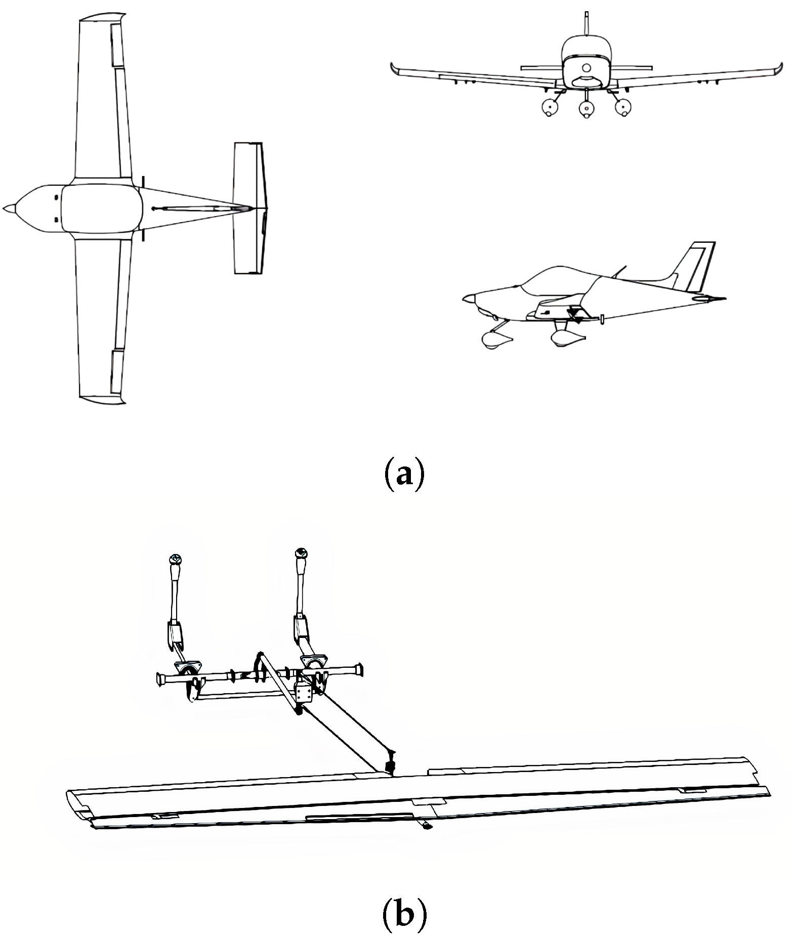
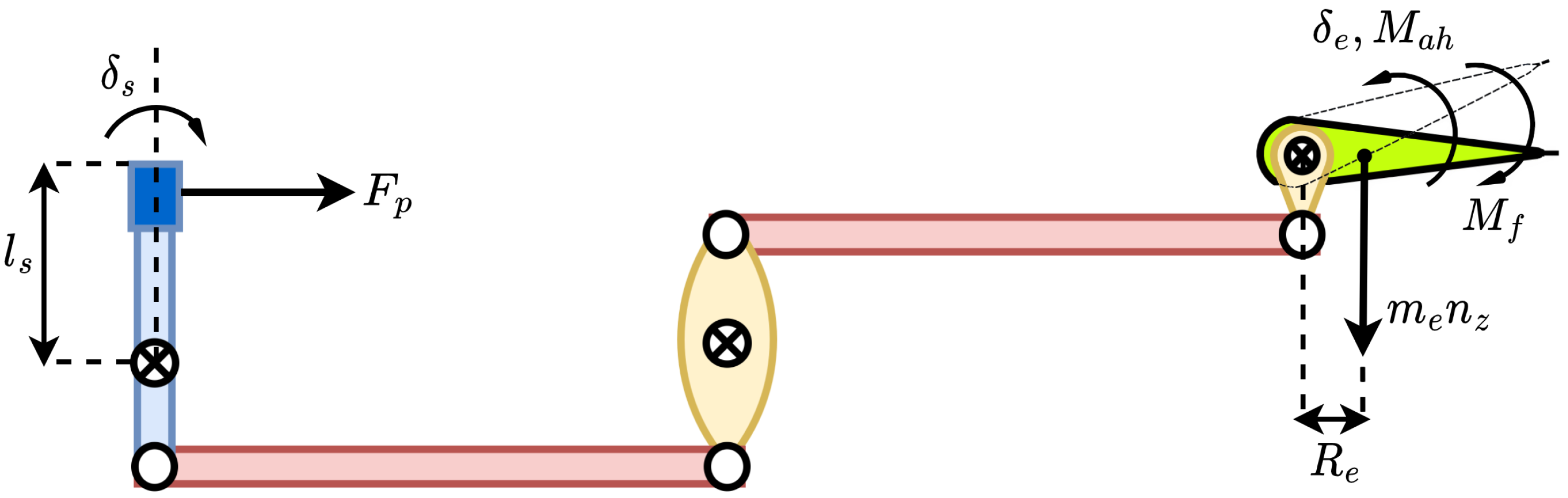
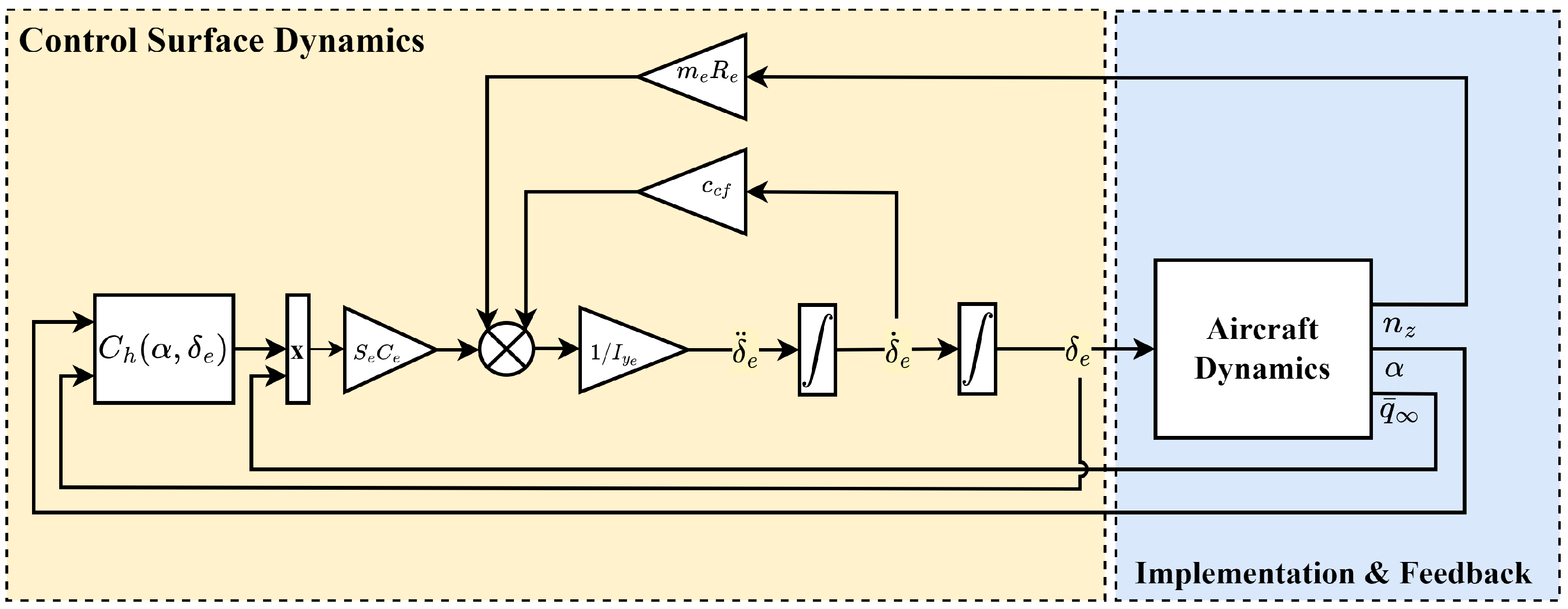
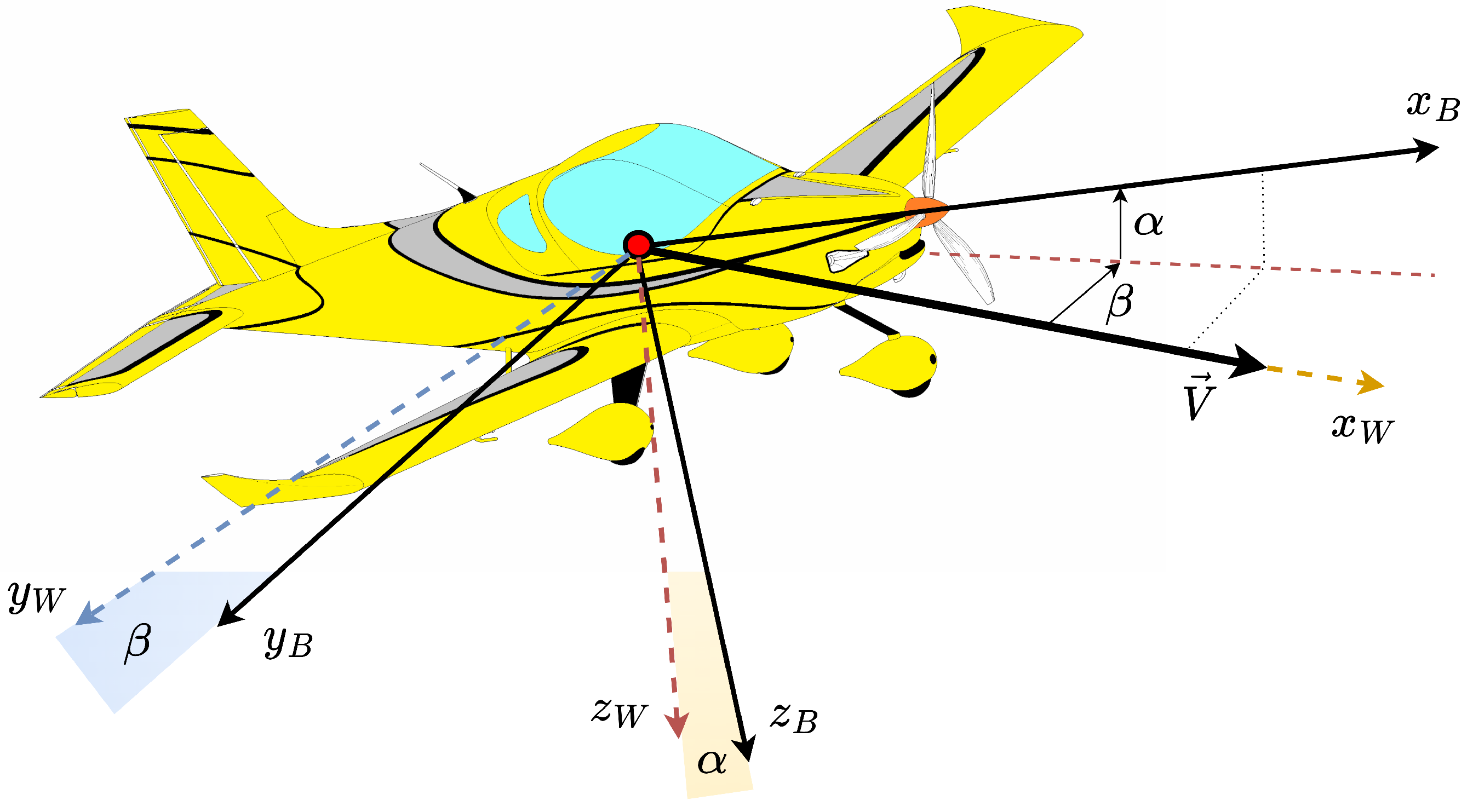
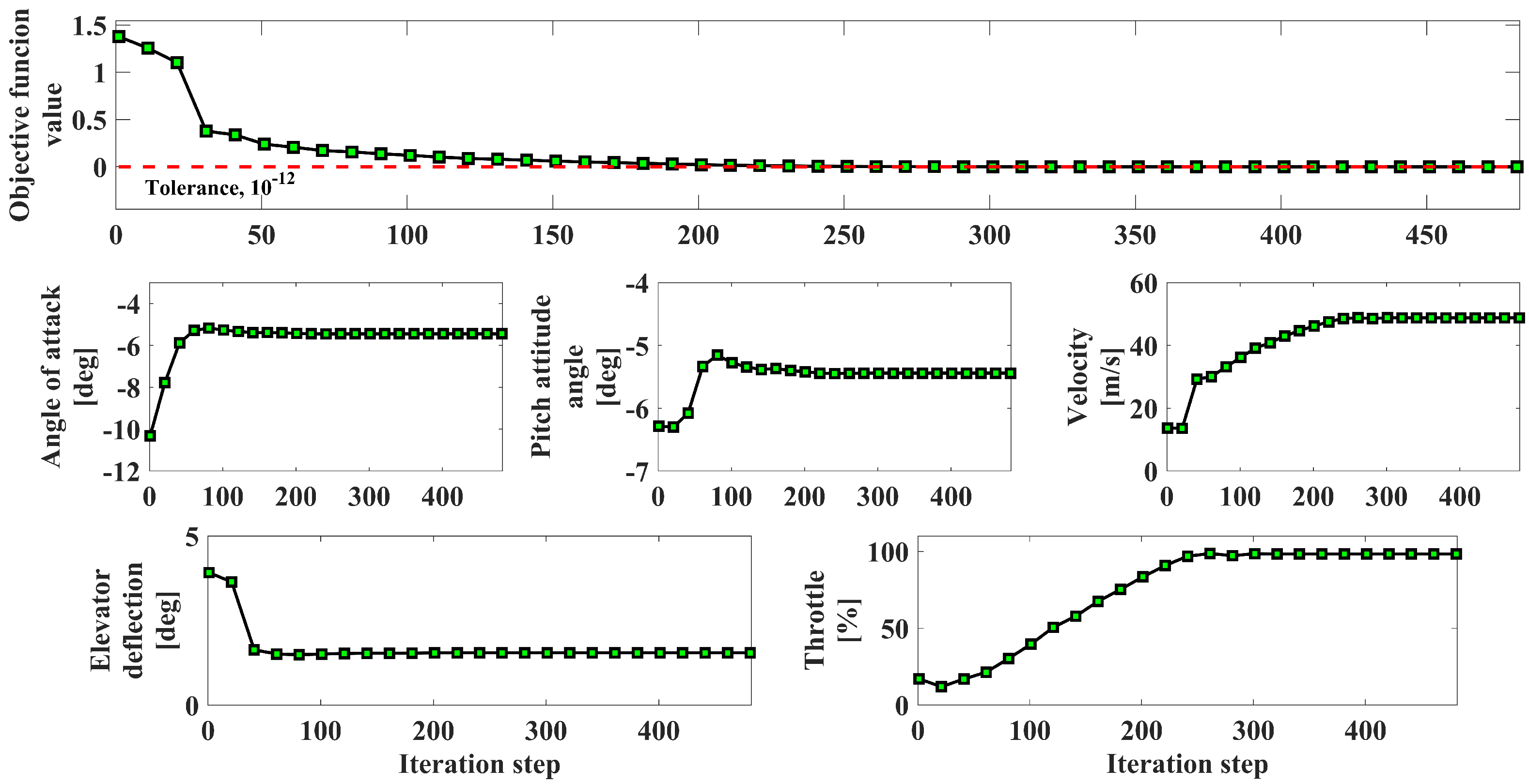
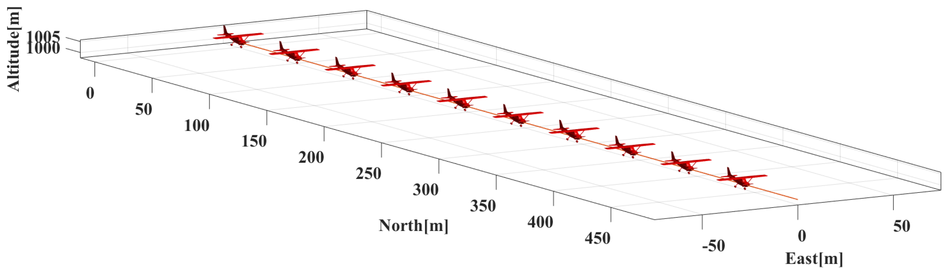
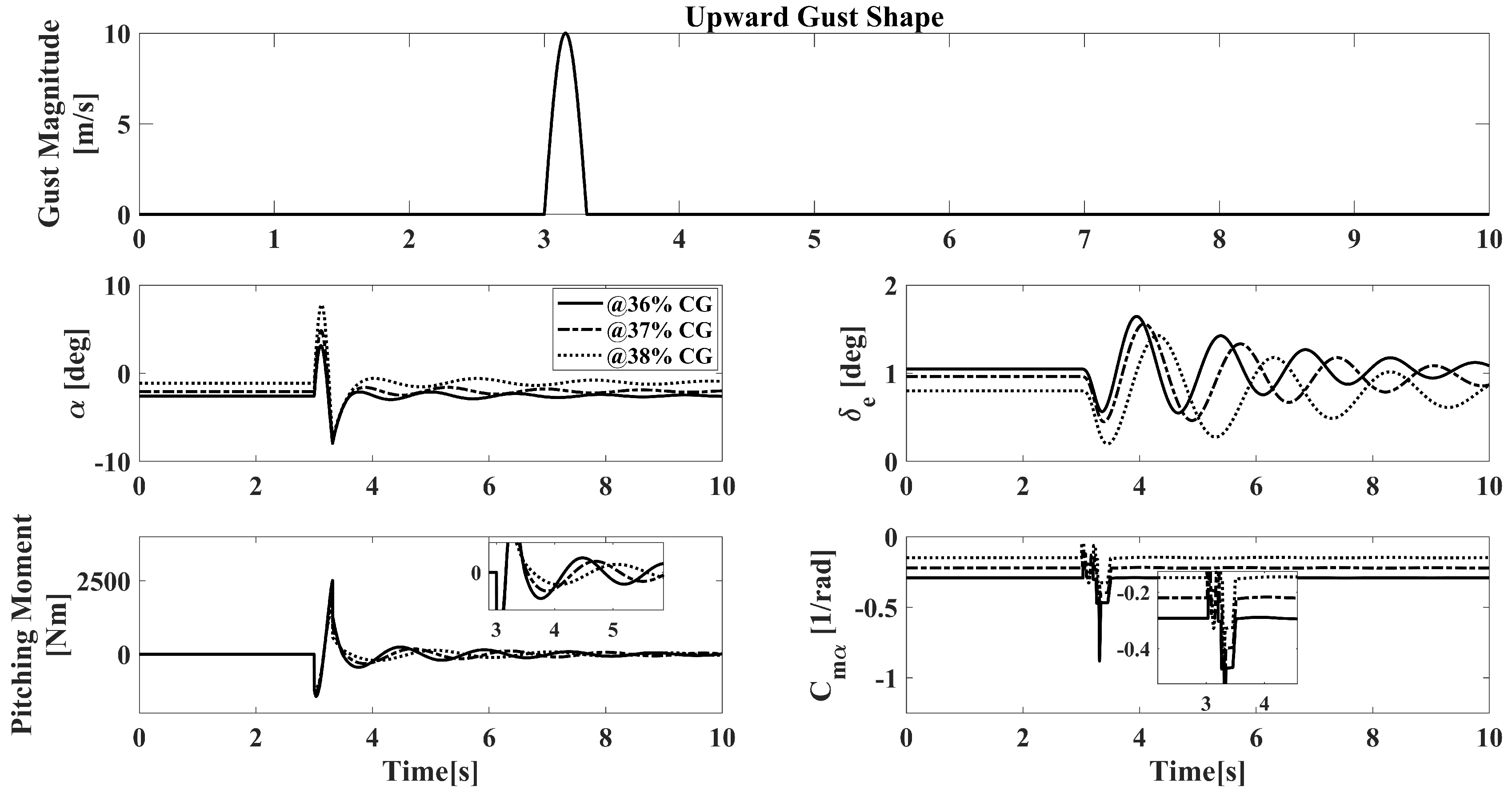
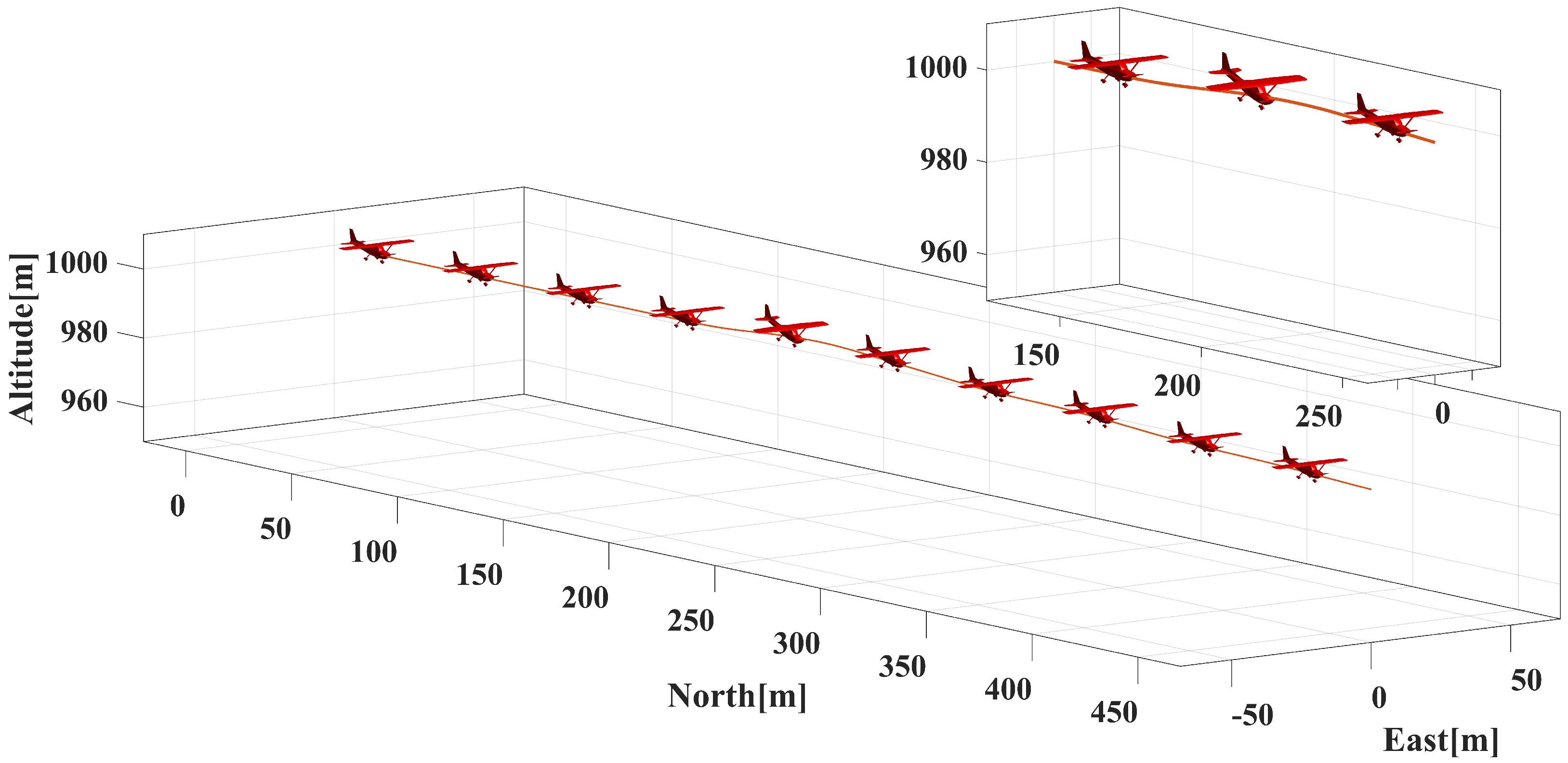
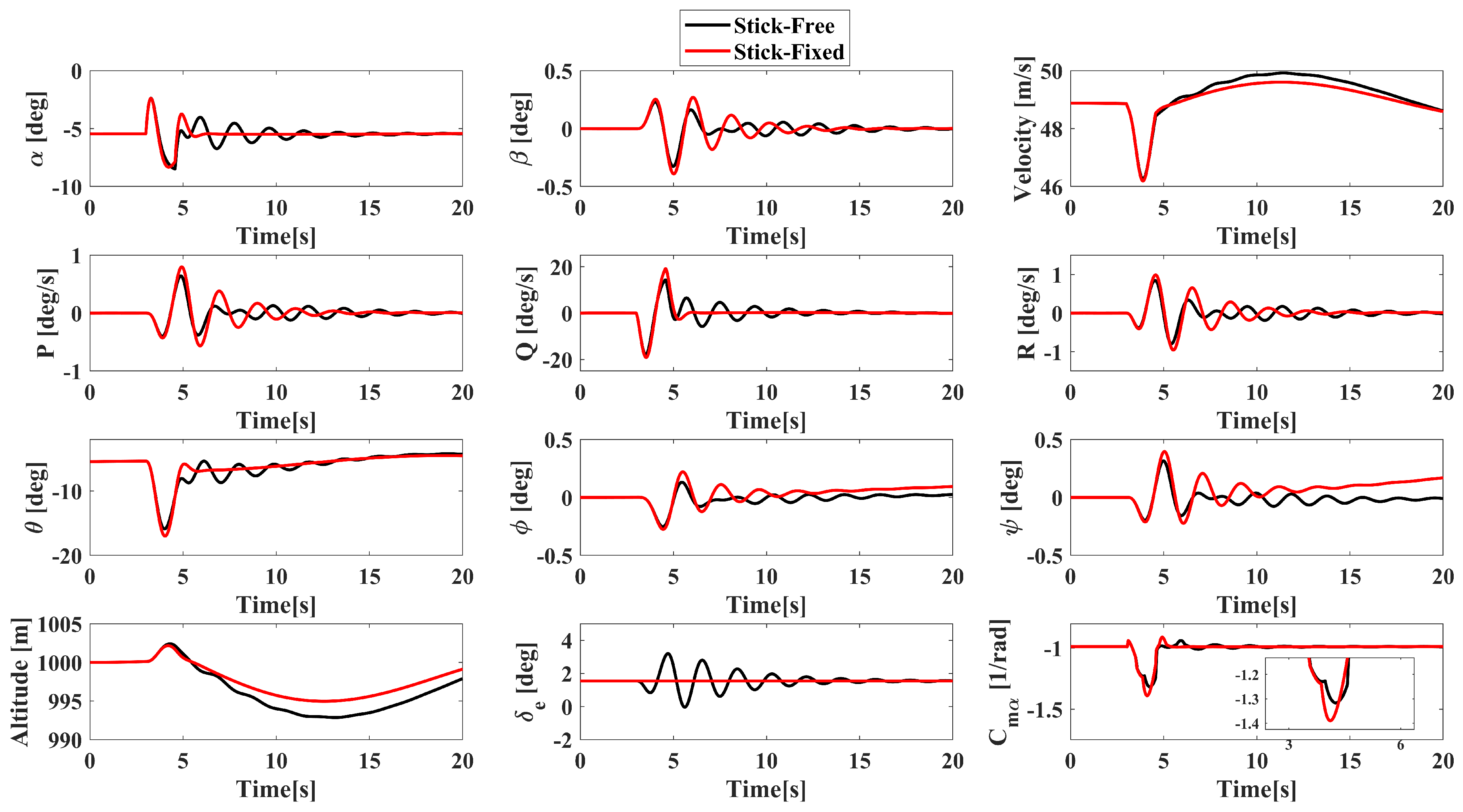
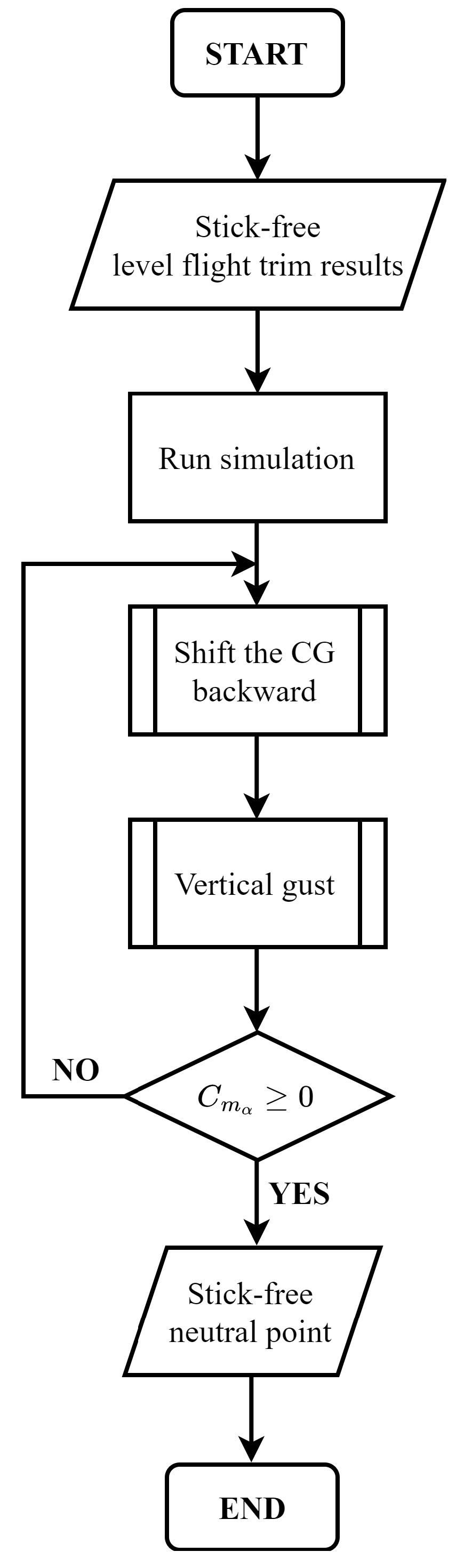
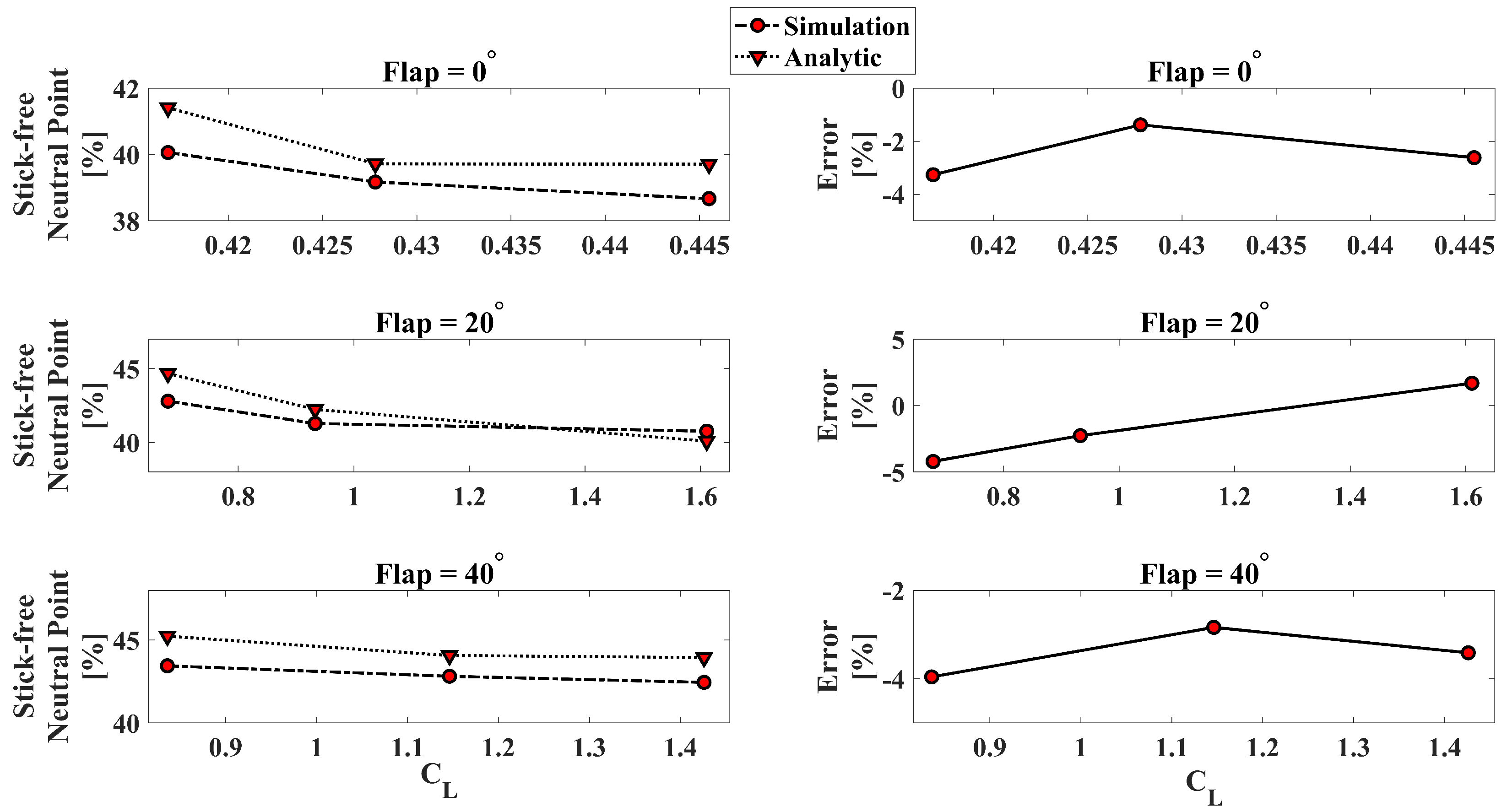
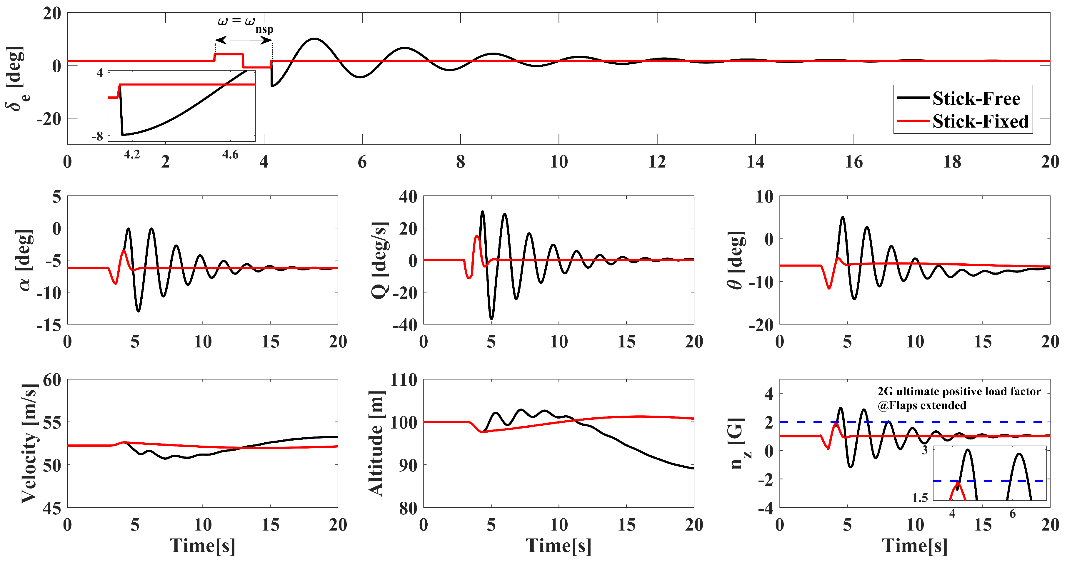
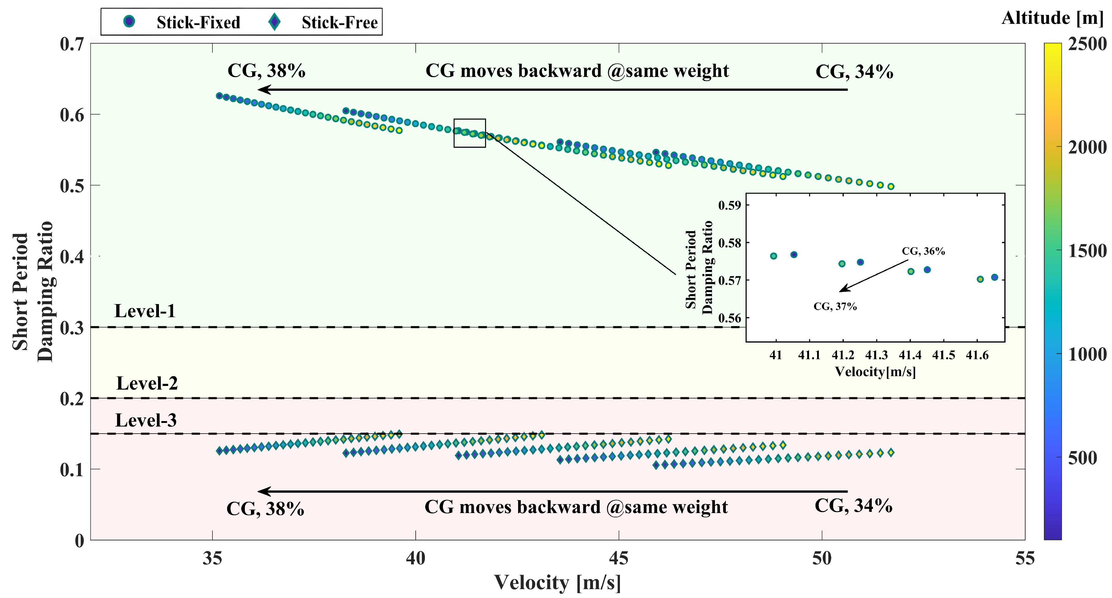
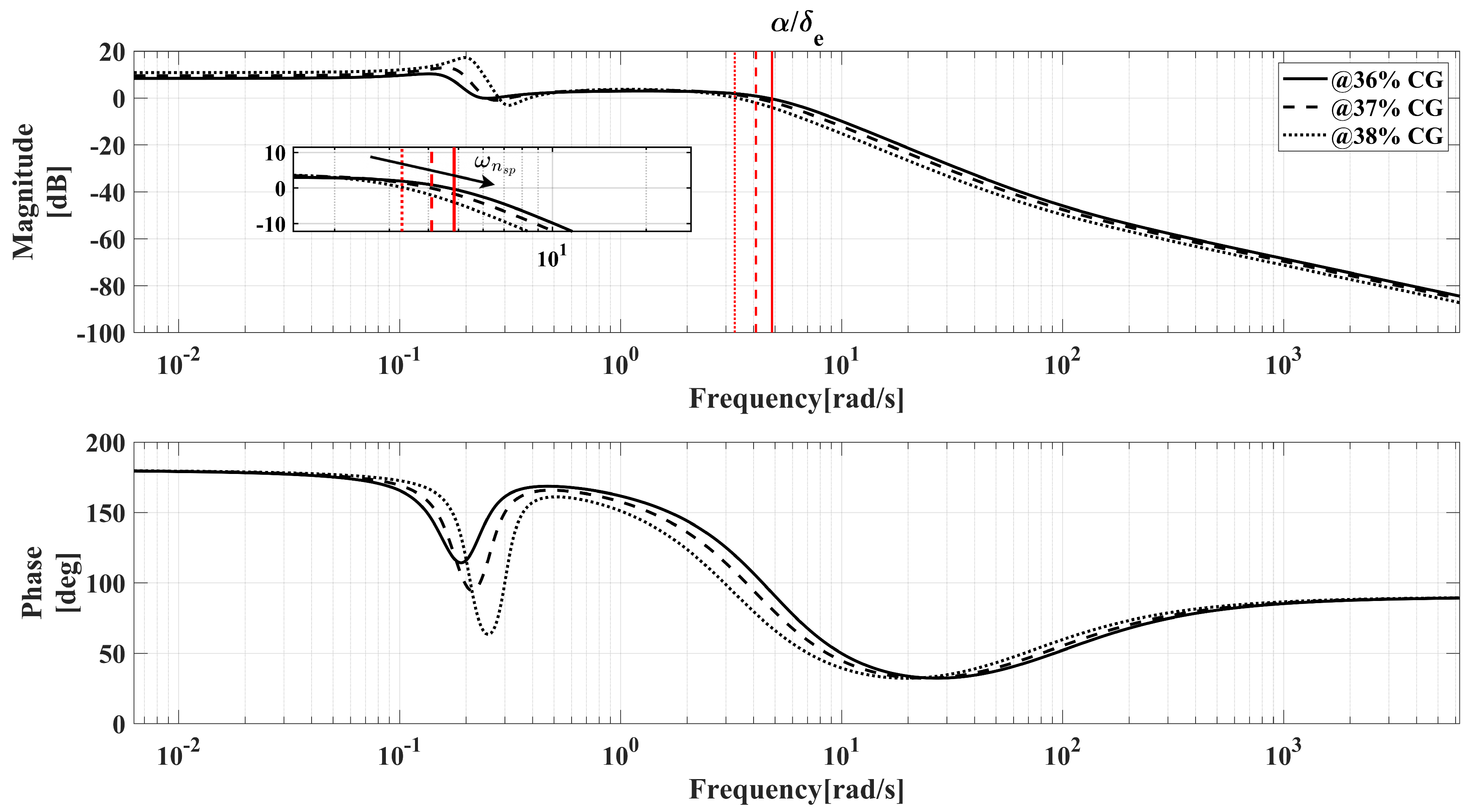
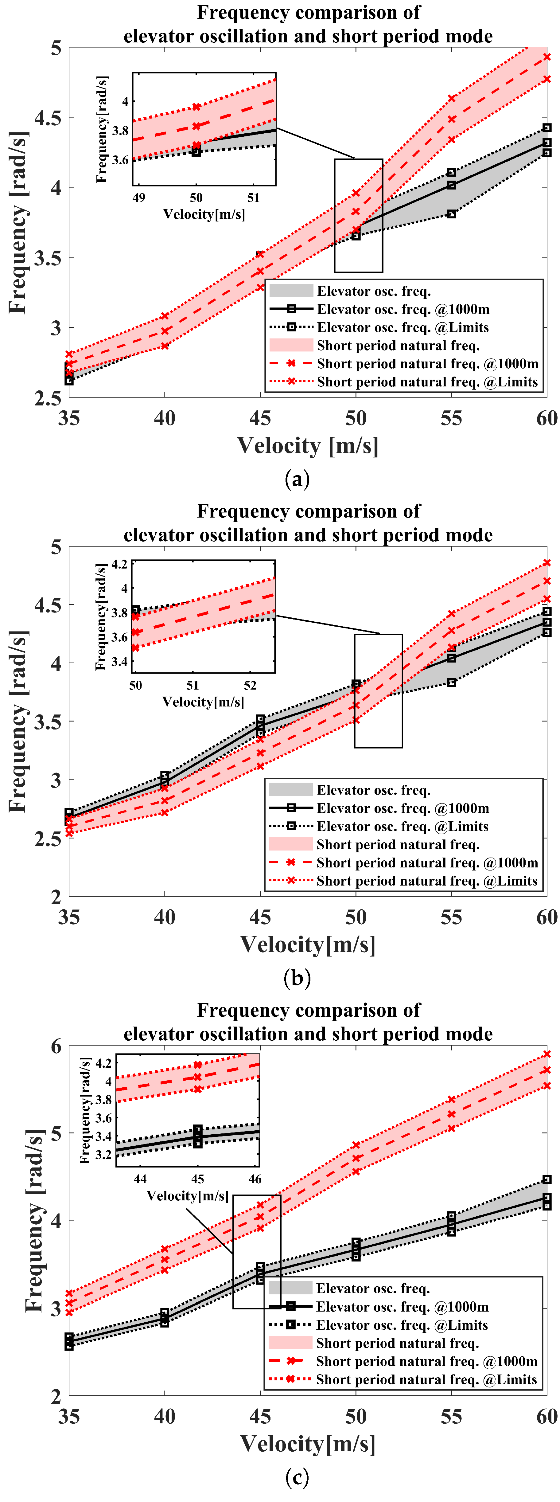
Table 1.
Fundamental properties of the baseline aircraft.
| Mass | Design Velocities | Physical Limitations | Altitude | |
|---|---|---|---|---|
| MTOM, kg | , knot | , knot | , deg | , ft |
| 750 | 45 | 120 | [, ] | 8000 |
Table 2.
Tuned hyper-parameter values.
| w | t | ||
|---|---|---|---|
| 0.4 | 1.8 | 2.5 | 0.1 |
Table 3.
Outputs of the optimization variables.
| Control Deflections | States | |||
|---|---|---|---|---|
| , deg | , % | , deg | , deg | , m/s |
| 1.55 | 98.88 | −5.44 | −5.44 | 48.88 |
Disclaimer/Publisher’s Note: The statements, opinions and data contained in all publications are solely those of the individual author(s) and contributor(s) and not of MDPI and/or the editor(s). MDPI and/or the editor(s) disclaim responsibility for any injury to people or property resulting from any ideas, methods, instructions or products referred to in the content. |
© 2023 by the authors. Licensee MDPI, Basel, Switzerland. This article is an open access article distributed under the terms and conditions of the Creative Commons Attribution (CC BY) license (https://creativecommons.org/licenses/by/4.0/).
Share and Cite
MDPI and ACS Style
Altunkaya, E.C.; Ozkol, I. Stick-Free Flight Stability Problem Revisited: A Modeling and Simulation Approach. Aerospace 2023, 10, 234. https://doi.org/10.3390/aerospace10030234
AMA Style
Altunkaya EC, Ozkol I. Stick-Free Flight Stability Problem Revisited: A Modeling and Simulation Approach. Aerospace. 2023; 10(3):234. https://doi.org/10.3390/aerospace10030234
Chicago/Turabian StyleAltunkaya, Ege Cagri, and Ibrahim Ozkol. 2023. "Stick-Free Flight Stability Problem Revisited: A Modeling and Simulation Approach" Aerospace 10, no. 3: 234. https://doi.org/10.3390/aerospace10030234
Note that from the first issue of 2016, this journal uses article numbers instead of page numbers. See further details here.