Experimental Research on the Hysteretic Behaviour of Pressurized Artificial Muscles Made from Elastomers with Aramid Fibre Insertions


1
SC Geometric SRL Brasov, 500386 Brasov, Romania
2
Department of Industrial Engineering and Management, Transilvania University of Brasov, 500036 Brasov, Romania
*
Author to whom correspondence should be addressed.
Actuators 2020, 9(3), 83; https://doi.org/10.3390/act9030083
Submission received: 21 August 2020
/
Revised: 6 September 2020
/
Accepted: 10 September 2020
/
Published: 11 September 2020
(This article belongs to the Special Issue Pneumatic Soft Actuators)
Abstract
:Inherent hysteresis behaviour of pressurized artificial muscles is complicated to understand and handle, calling for experimental research that allows the modelling of this phenomenon. The paper presents the results of the experimental study of the hysteretic behaviour of a small-size pneumatic muscle. The specific hysteresis loops were revealed by isotonic and isometric tests. Starting from hypothesis according to that the tube used for the pneumatic muscle is made entirely of aramid fibres enveloped by an elastomer material that merely ensures their airtightness, the paper presents the hysteresis curves that describe the radial and axial dimensional modifications as well as the variation of the developed forces for different feed pressures. The obtained third-degree polynomial equations underlie the configuration of high-performance positioning systems.
1. Introduction
Pressurized artificial muscles (PAM) are contractile actuators operated by means of liquid or gas mediums. Their role is to allow controlled linear or angular displacements of a magnitude depending on the pressure of the working fluid.
Directing the linear or angular deformation of a pressurizes artificial muscle by certain directions is possible by adopting an optimised geometry and by selecting adequate materials. Certain types of synthetic fibre reinforced elastomers lend themselves for building pressurized artificial muscles capable of a performance that exceeds that of a number of pneumatic cylinders.
The first known version of synthetic pneumatic muscle was developed in 1872 by Professor Franz Reuleaux and is described as a flexible pneumatic actuator for medical applications [1]. In 1930 the Russian inventor S. Garasiev put forward a new constructive variant of a pneumatic muscle [2], followed in 1950 by J.L. McKibben who built a new version of an actuator designed to operate a pneumatic orthesis [3]. McKibben muscles are made of a hyper-elastic bladder covered by a braided fibre sleeve.
In 1953 A.H. Morin patented the reinforcing of pneumatic muscle elastic envelopes with textile fibres [4]. The role of such fibre insertions was to limit radial muscle deformation in favour of axial displacement. The years to follow saw the development of numerous other constructive solutions of pneumatic muscles, such as the ones put forward by Yarlott and Mass [5], Takagi and Sakaguchi [6], Kukolj [7], Paynter [8], or Daerden [9].
The study discussed in this paper is focused on linear pneumatic muscles whose operation entails the deformation of an elastic membrane under the action of compressed air. Pneumatic Artificial Muscles (PAMs) are actuators that resemble human muscles. An element that supports this statement is for example the loose-weave nature of the outer fibre shell, which enables pneumatic muscles to be flexible and to mimic biological systems. Another argument is that the relationship between force and extension in pneumatic muscles mirrors what is seen in the length–tension relationship in biological muscle systems [10]. Another common characteristic of the two types of muscles is the adjustable compliance, the inverse of rigidity, resulting from the non-linear dependency between the force developed by the muscle and the stroke that is carried out. The static force developed by biological muscles is generated by the nervous impulses produced by the alpha motor neurons. These come into contact with the muscle fibre by means of the neuromuscular junctions the role of that is to transmit a unidirectional action command at a frequency and amplitude set by the nervous system. In the case of pneumatic muscles, the axial contraction is determined by the air pressure, the precision, and control over muscle behaviour being at a lesser level compared to biological muscles.
Similarly to the human muscle fibre they mimic, PAMs draw upon from a number of beneficial features, such as the capacity to absorb and resist shocks, low weight and volume (a high power-to-volume ratio: 1.1 W/cm3) [11], a high power-to-mass ratio (500 W/kg–2 kW/kg) [12], elasticity, compliance, easy connectivity, and safe operation.
The deployment of pneumatic muscles has, however, certain disadvantages, for example the necessity of using in mobile applications sometimes large and heavy pneumatic components, such as the phenomenon of hysteresis and a threshold pressure that is the pressure value that has to be overcome so that the actuator will deform axially. The availability of miniaturized pneumatic control apparatus and the possibility of using non-conventional sources of compressed air [13] allow the elimination of the first mentioned disadvantage, thus hysteresis remains the major disadvantage of pneumatic muscles that renders them unsuitable for accurate positioning systems.
The phenomenon of hysteresis was traced experimentally by plotting the curves describing the dependency of the muscle’s deformation or of the force developed by it on the feed pressure. The occurrence of hysteresis is explained by internal tensions generated in the material of the elastic tube, while it deforms when subjected to the pressure of compressed air, but also by internal friction between the inserted fibres and by the friction between these fibres and their enveloping elastic material. These are the causes responsible also for the inertia that occurs at the motion onset of the pneumatic muscle’s free end, a phenomenon that can be quantified by the so-called threshold pressure. This inertia manifests at the initiation time of the motion by zero axial deformation of the pneumatic muscle despite the growing feed pressure.
Hysteresis in pneumatic muscles is described by several mathematical models. Minh et al. [14] and Yeh et al. [15] developed a hysteresis model by applying a Maxwell-slip model. Van Damme et al. [16] proposed a Preisach-based hysteresis model, while Zang et al. [17] and Xie et al. [18] base their studies on a modified generalized Prandtl–Ishlinskii (GPI) model. The disadvantage of the known models is that they are specific only for the categories of muscles they were developed for and consequently are not suitable for generalisation.
Several researchers, such as Zhao et al. [19], Zhu et al. [20], or Schreiber et al. [21] studied the possibilities of compensating the specific non-linearities of systems actuated by pneumatic muscles caused by hysteresis. These studies led to the identification of extremely complex problems related to the control of the systems including pneumatic muscles. Such complexity is determined by the presence of numerous parameters that are difficult to quantify.
The latest generations of pressurized artificial muscles are made of an elastomer tube reinforced with synthetic fibre insertions. The elastomers are latex rubber, silicone rubber, and other synthetic rubbers, while the fibres can be made of metal, nylon, carbon fibre, glass fibre, and other synthetic high-strength fibres [22]. Research conducted so far on the materials used for pneumatic muscles were focused on the non-linearity of the tube material and on the geometric non-linearity and reorientation of the inserted fibres. Known studies in this context are authored by Kydoniefs [23], followed by Matsikoudi-Iliopoulou [24], and Liu and Rahn [25].
An analysis of the research conducted to date yields the conclusion that, despite a major interest in such actuators, no definitive static model has been established. The difficulty in developing such a model can be explained by the “soft” character of the artificial muscle, combining elastomer physics with textile physics [26].
Given the known occurrence of hysteresis in the operation of pneumatic muscles this paper proposes a study of this phenomenon starting from the constructive structure of the muscles. The study was conducted on pneumatic muscles manufactured by Festo AG. & Co, Esslingen, Germany, frequently used in modern pneumatic actuations.
The structure of the paper includes a second section that describes the construction of Festo pneumatic muscles with an emphasis on the reinforcement of the elastic tube with aramid fibre insertions. Further, it summarizes the values of the significant characteristics of the polymer materials used for the elastic tube and the reinforcing fibre insertions. The third section of the paper presents the theoretical and experimental results of the research conducted on the hysteretic behaviour of the studied pneumatic muscle. This section also presents the experimental installation, the measured data, the hysteresis loops, and the resulting regression functions. The last section of the paper comprises the conclusions of the study.
2. Construction of Pneumatic Muscles
In recent years, several manufacturers have taken an interest in linear pneumatic muscles. Thus, for example, the Bridgestone rubber company (Japan) commercialized the idea in the 1980s under the name of Rubbertuators. Shadow Robot Company (London, UK) put forward the Shadow Air Muscle (SAM) that can contract by up to 37% of its original length [27].
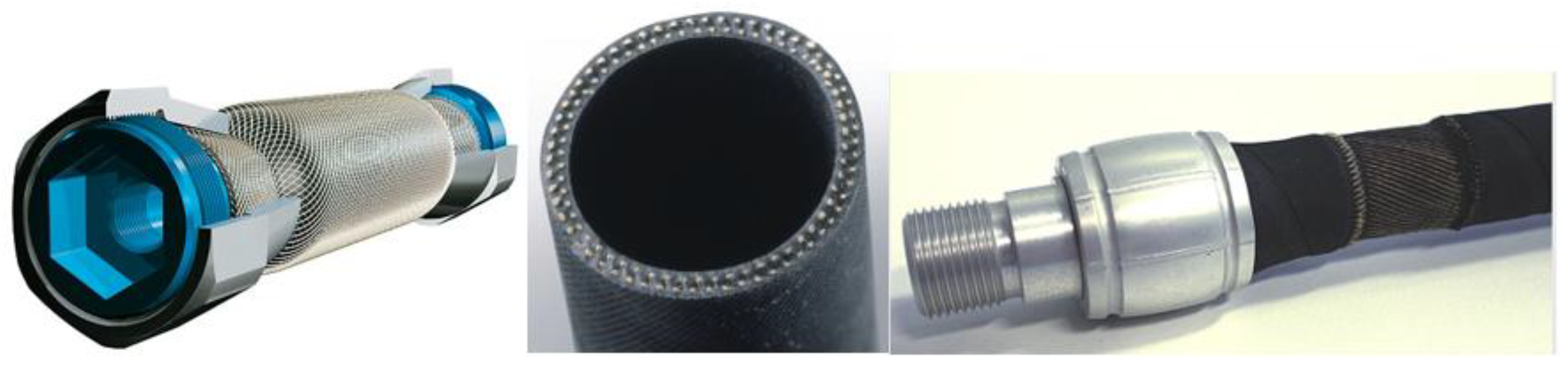
The main industrial manufacturer of pressurized artificial muscles is Festo AG & Co, Esslingen, Germany. The central element of these pneumatic muscles is a flexible tube made of an aramid fibre-reinforced rubber composite material. The elastomer is a chloroprene rubber and forms a matrix that integrates a 3D mesh of inelastic aramid fibres laid out in a diamond pattern (Figure 1) [28,29].
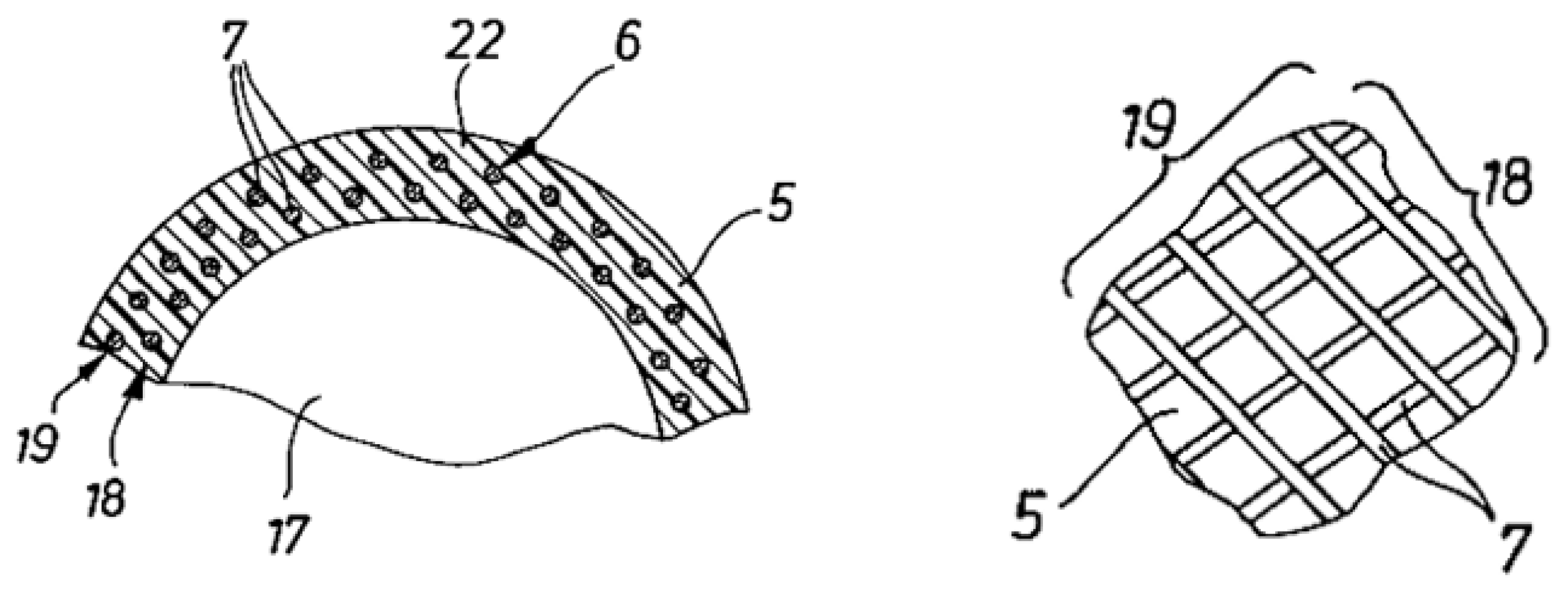
The idea of reinforcing the flexible tube with a 3D mesh of synthetic fibres emerged as a solution to improve behavioural characteristics, such as inhibiting radial in favour of axial deformation and increasing the flexibility and durability of the entire assembly. The concept was borrowed from the structure of motor vehicle tyres and improved by the more precise positioning of each aramid fibre, so that despite the greater number of fibres none of them touches the other. Figure 2 presents the layout patterns of the aramid fibres in the tube, patented by Festo [30].
Embedded in the wall of the elastic tube are two layers of fibres not in contact with one another (denoted by 18 at the interior and 19 at the exterior, respectively) and following a diamond layout. The angle between the fibres of the two layers varies with the axial deformation of the entire assembly when compressed air is fed to the pneumatic muscle. The material of the elastic tube (22) separates each fibre (7) individually and each layer so that they never touch. The separation of the fibres by embedding them into the elastomer mass (the tube wall) ensures that the possibility of internal friction between neighbouring fibres or layers is eliminated.
The elastic tubes of Festo pneumatic muscles are manufactured in a range of interior diameters of 10, 20, or 40 mm, the thickness of the chloroprene wall varying between one and two millimetres. In small diameter muscles, the number of fibres is 60, laid out in two layers. In larger diameter muscles, the number of fibres can be as high as 240. The diameter of each fibre varies from 0.1 to 0.3 mm [31,32].
When fed compressed air, the Festo pneumatic muscles contracts swiftly and generates a traction force along its longitudinal axis. The force reaches its maximum value as soon as the contraction starts, while at the end of stroke the developed force is null. At the same time, with the generation of that force, the muscle shortens proportionally with the increase in the internal pressure, its maximum contraction being approximately 20% of its initial length.
Pneumatic muscle performance is determined inter alia, by the main characteristics of the materials the flexible tube and the fibre insertions are made of. In the case of the tube made of chloroprene rubber, important qualities are elasticity, fatigue strength, and loss by hysteresis under variable strain. It is the elasticity of the tube material that causes the inherent hysteretic behaviour of the Festo muscle. In combination with fibres, such as aramid fibres, the tensile strength is increased considerably with a reduction in extendibility.
Embedded in the elastic material of the tube are the aramid fibres (aromatic polyamide); this is a material standing out by a high strength-to-weight ratio, good resistance to abrasion and cutting, stiffness, excellent dimensional stability, and heat-resistance properties. These unique characteristics derive from the combination of stiff polymer molecules and a strong crystal orientation, as well as from the close interaction between the polymer chains due to the hydrogen bonds.
Table 1 features the values of the main characteristics of the polymer materials used for the elastic tube and the fibre insertions.
3. Experimental Research Concerning the Hysteresis of Pneumatic Muscles
The studies on pneumatic muscle hysteresis have identified several possible causes for the occurrence of this phenomenon, the most important ones being (i) the friction between the reinforcing fibre insertions and the material of the elastic tube, and (ii) the inherent hysteresis of the elastic tube material caused by its straining once the muscle volume is modified [26,33].
With regard to the first mentioned cause, it is known that an elastomer of chloroprene type is capable of adhering to most other materials, enabling different hybrid constructions. The static friction coefficient between chloroprene rubber and aramid is high and, thus, impedes a relative displacement between the fibres and the surrounding material. The fibres adhere to the tube and consequently no relative motion occurs; hence the hysteresis generated from this cause is practically non-existent.
Thus, it follows that responsibility for the occurrence of hysteresis is the second previously mentioned cause. Feeding compressed air to the elastic tube strains deforms its walls, meaning that part of the work expended is converted into elastic deformation energy. This energy is responsible for the tube reverting to its (approximate) initial form and dimensions once the load disappears. Another part of the work is converted into heat and this loss of energy determines the occurrence of the hysteresis phenomenon.
Further on presented are the results of the isotonic and isometric tests conducted on a small pneumatic muscle (MAS-10-45N-AA-MC-O-ER-EG) manufactured by Festo. The dimensional and operational characteristics of this muscle are interior diameter of the tube: 10 mm, exterior diameter of the muscle: 13.67 mm, length of the active part: 45 mm, maximum working pressure: 8 bar, largest possible axial contraction: 9 mm, maximum force that can be generated: 600 N.
3.1. Evaluation of the Hysteresis of the Muscle Radial Deformations
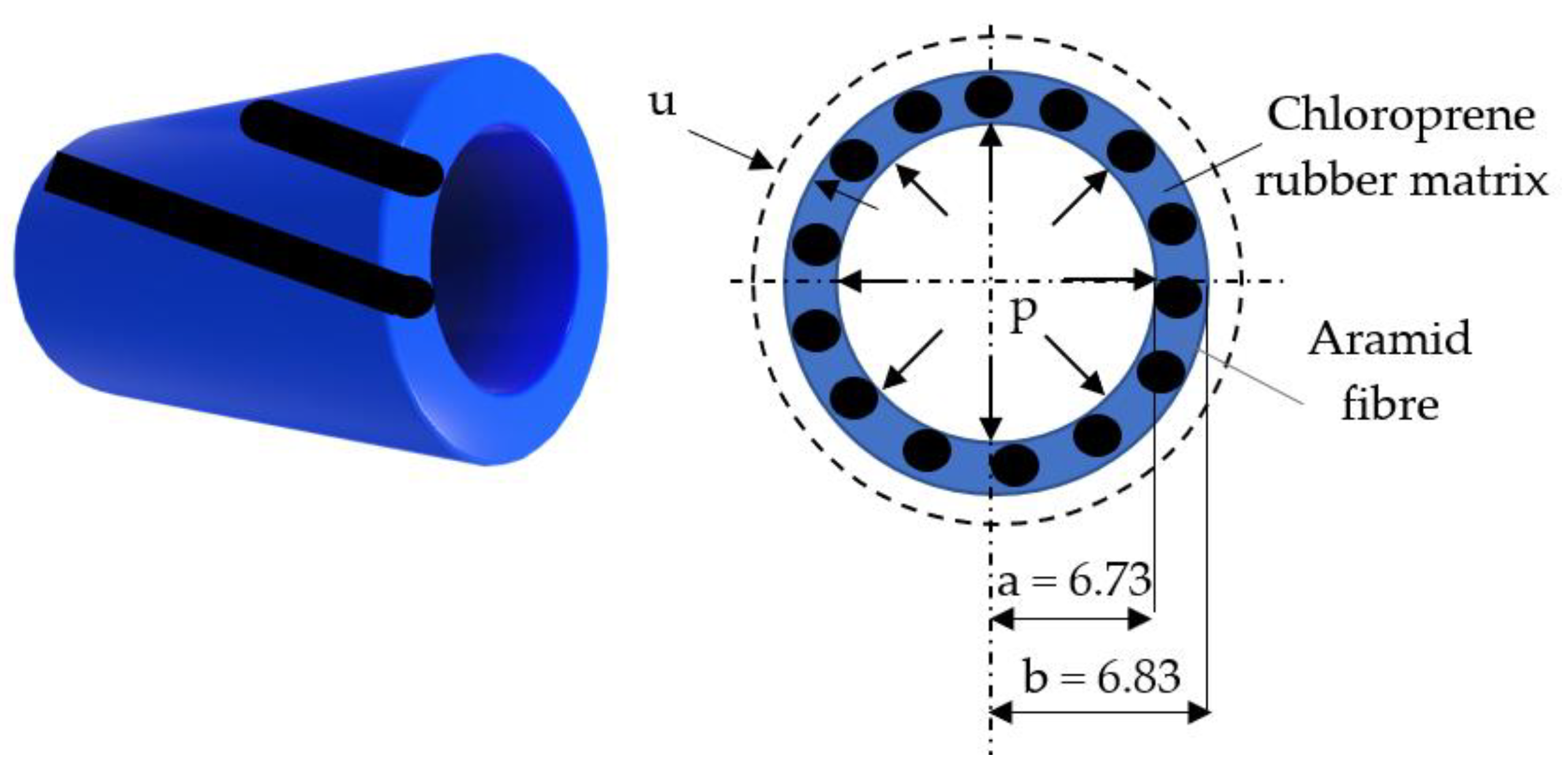
The theoretical study was focused on the manner of the muscle’s radial deformation based on a model of a thin-walled tube loaded with an internal pressure p. The role of a pneumatic muscle is to contract axially rather than radially for which purpose aramid fibres were inserted. Table 1 shows that Young’s Modulus of aramid fibres is significantly greater than that of chloroprene rubber for which reason aramid will be assumed as the material of the thin-walled tube in calculations. This assumption is acceptable even if in fact the aramid fibres form a permeable mesh incapable of retaining compressed air. This mesh, however, is integrated in the elastic material of the tube, and it is the latter that renders the assembly impermeable to air, while not altering its deformation behaviour. Figure 3 shows the dimensions of the tube.
Upon being fed compressed air the tube shortens axially and increases its exterior diameter by 2∙u, where the radial deformation u is computed by Equation (1):
with the following notations: a, b—interior/exterior radii of the undeformed tube, p—compressed air pressure, and E is Young’s Modulus of the tube material (aramid fibres).
The exterior diameter of muscle deformed by compressed air is computed by Equation (2):
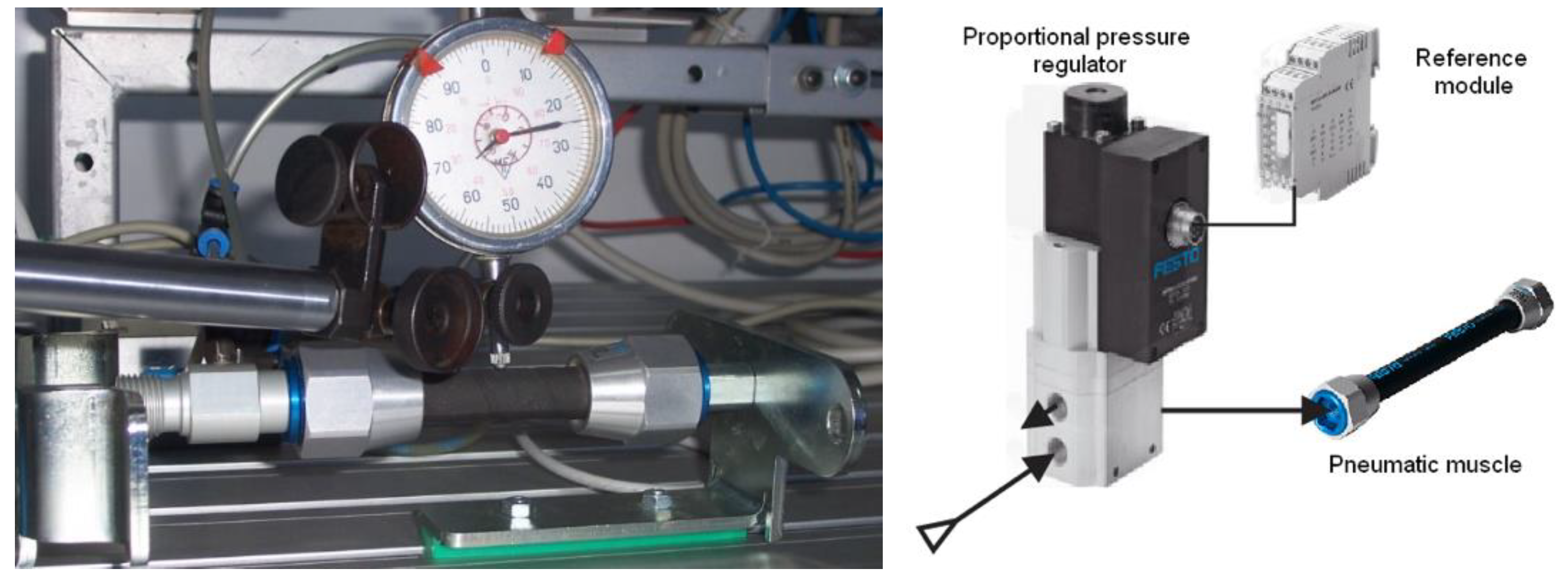
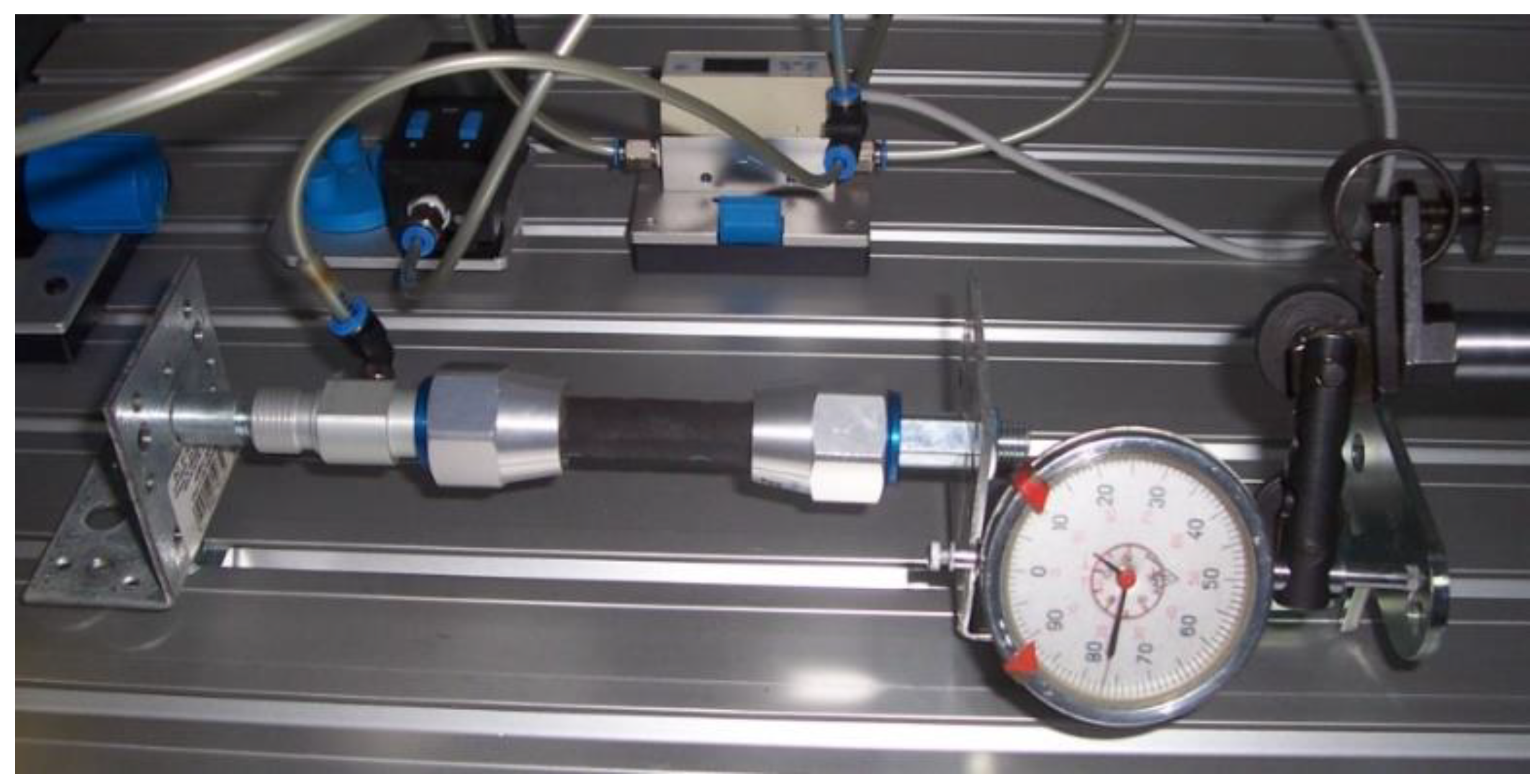
The modification of the pneumatic muscle’s exterior diameter when charged with compressed air and discharged, respectively, was studied by means of isotonic contraction tests, when the muscle carries out work consequently to modifying its length. Measurements were conducted with a dial indicator fitted, as shown in Figure 4.
Compressed air is fed to the muscle through an MPPES-3-1/4-6-010 proportional pressure regulator controlled by an MPZ-1-24DC-SGH-6-SW reference module (produced by Festo AG & Co Esslingen, Germany). This control diagram enables the slow and uniform charging of the pneumatic muscle without introducing shocks.
The diameter values of the inflating muscle resulted by adding the radial deformation values shown by the dial indicator times 2 to the initial value of the diameter in the relaxed state of the muscle at 0 bar pressure. The diameter values of the deflating muscle were resulted by subtracting from the diameter value at 6 bar pressure the radial deformation values shown by the dial indicator times 2. The measurements were repeated five times and five cycles of inflation/deflation with air of the pneumatic muscle were conducted. The five sets of values presented in the tables do not pertain to tests carried out successively; each test was performed at different moments far apart in time. This working method was necessary in order to reveal any possible modification of the hysteresis curves with the ageing of the muscle.
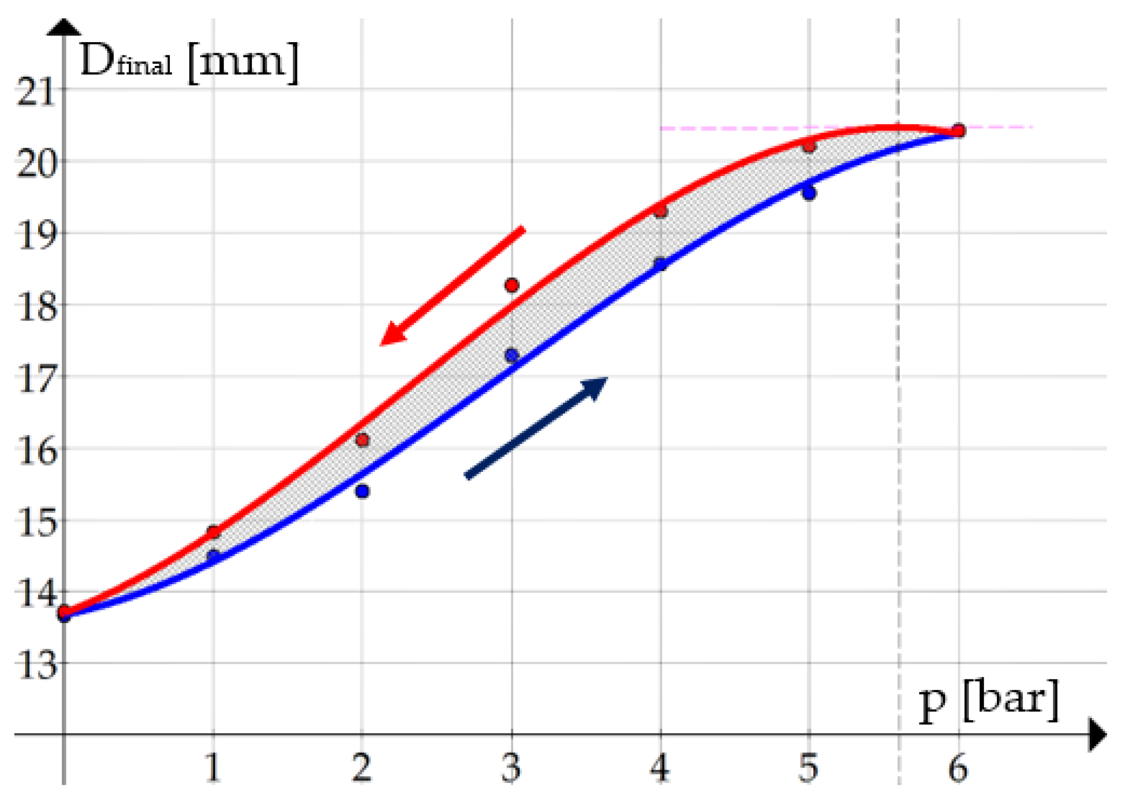
The experiment worked with incremental pressure levels of one bar, from 0 to 6 bar. Upon reaching each level of the charging pressure, the measurement was performed after one minute stabilizing time of the muscle form. Table 2 and Figure 5 show the results obtained in the five working cycles.
In Table 2, the arithmetic mean and the standard deviation illustrate the statistical dispersion of the measured values. The values of the standard deviation are noticeably small, close to zero, and indicate a low uncertainty of the measurements.
The measurements show that for any given value of the pressure, the muscle diameter is greater at deflation than at inflation. The greatest difference of 0.98 mm between the measured diameters at inflation and deflation, respectively, occurs at a pressure of 3 bar.
In the above graph, the dots represent the measured muscle diameters, while the continuous lines correspond to the polynomial regression curves obtained by the Graph application. The functions that describe with the best accuracy the muscle diameters at inflation and deflation, respectively, at pressures varying from 0 to 6 bar are the following:
Pressure p is the argument of the obtained third-degree polynomial equations. The variation of this quantity (the pressure) causes the different contractions and/or forces developed by the muscles. It is important to know these functions when the proportional pressure regulator is to be controlled by means of the reference module MPZ-1-24DC-SGH-6-SW. A specially developed computer programme based on the experimentally determined polynomial equations is loaded to a PLC (Programmable Logic Controller). By means of the external setpoint input of the reference module the PLC sends an electric signal to the proportional pressure regulator whose voltage is continuously modified according to the experimentally obtained polynomial functions. This affects the desired variation of air pressure in the pneumatic muscle and consequently the desired contractions and forces.
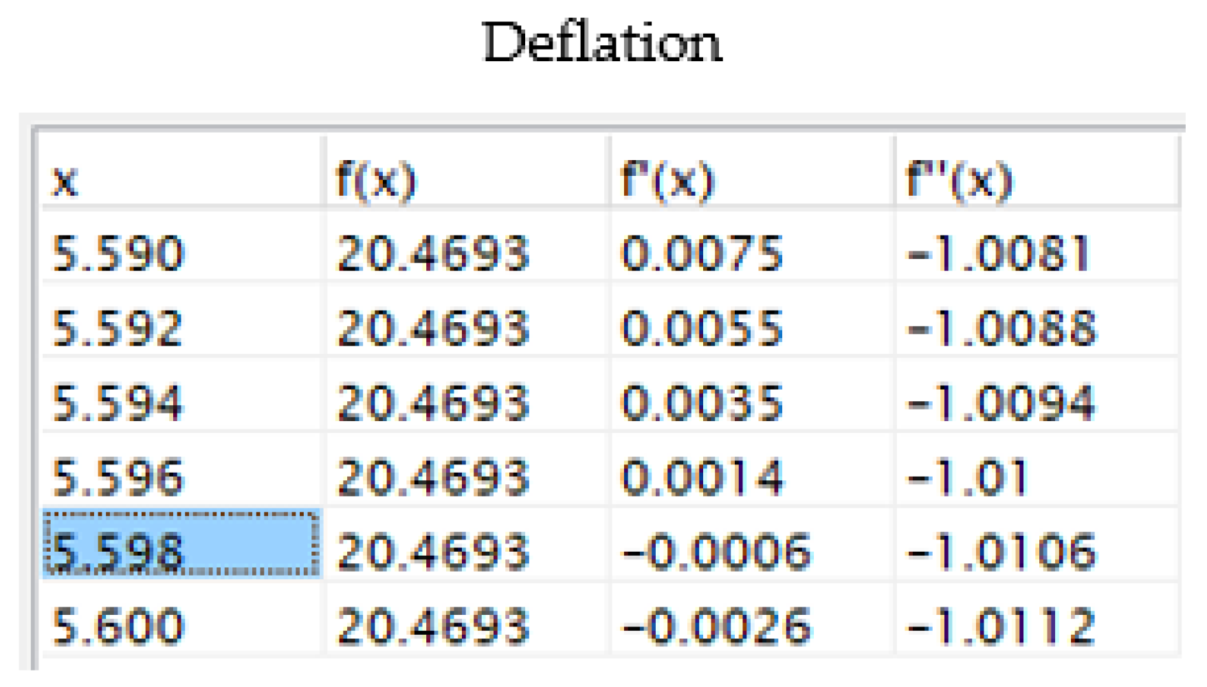
An analysis of the above curves reveals that at the inflation of the muscle in no section the tangent to the curve has a zero slope, hence there is no threshold pressure. On the deflation curve, however, a zero slope of the tangent to the curve can be noticed for p = 5.597 bar. This is considered to be a threshold pressure, because muscle relaxation starts only from this value downwards. The explanation of this phenomenon consists in the fact that feeding compressed air causes internal tensions in the material of the elastic tube that deform its walls. The work is partially transformed into elastic deformation energy and the rest into heat. The energy loss by heat emission determines the occurrence of the threshold pressure that inhibits the precise control of force and displacement. A high value of the threshold pressure delays the actuation, so that the contraction of the pneumatic muscle becomes perceivable only once this value has been exceeded.
For the rest of the working pressure (<5.597 bar) the slope of the tangent to the curve is different from zero, as shown by the data in Figure 6 (the first order derivative of the function is different from zero).
3.2. Evaluation of the Hysteresis of the Muscle Axial Deformations
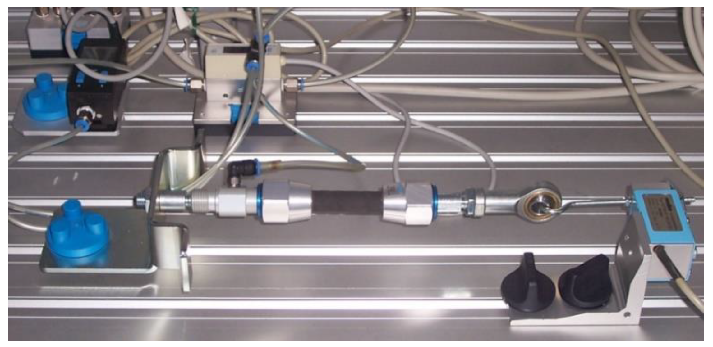
In the second phase of experimental research, the axial displacement of the pneumatic muscle’s free end was measured. Figure 7 shows the experimental set-up used for data collection [34].
The length values of the inflating muscle resulted by subtracting the axial contraction values shown by the dial indicator from the initial muscle length in a relaxed state (45 mm) at 0 bar pressure. The length values of the deflating muscle (when decreasing the pressure), resulted by adding the axial deformation values shown by the dial indicator to the muscle length at 6 bar pressure.
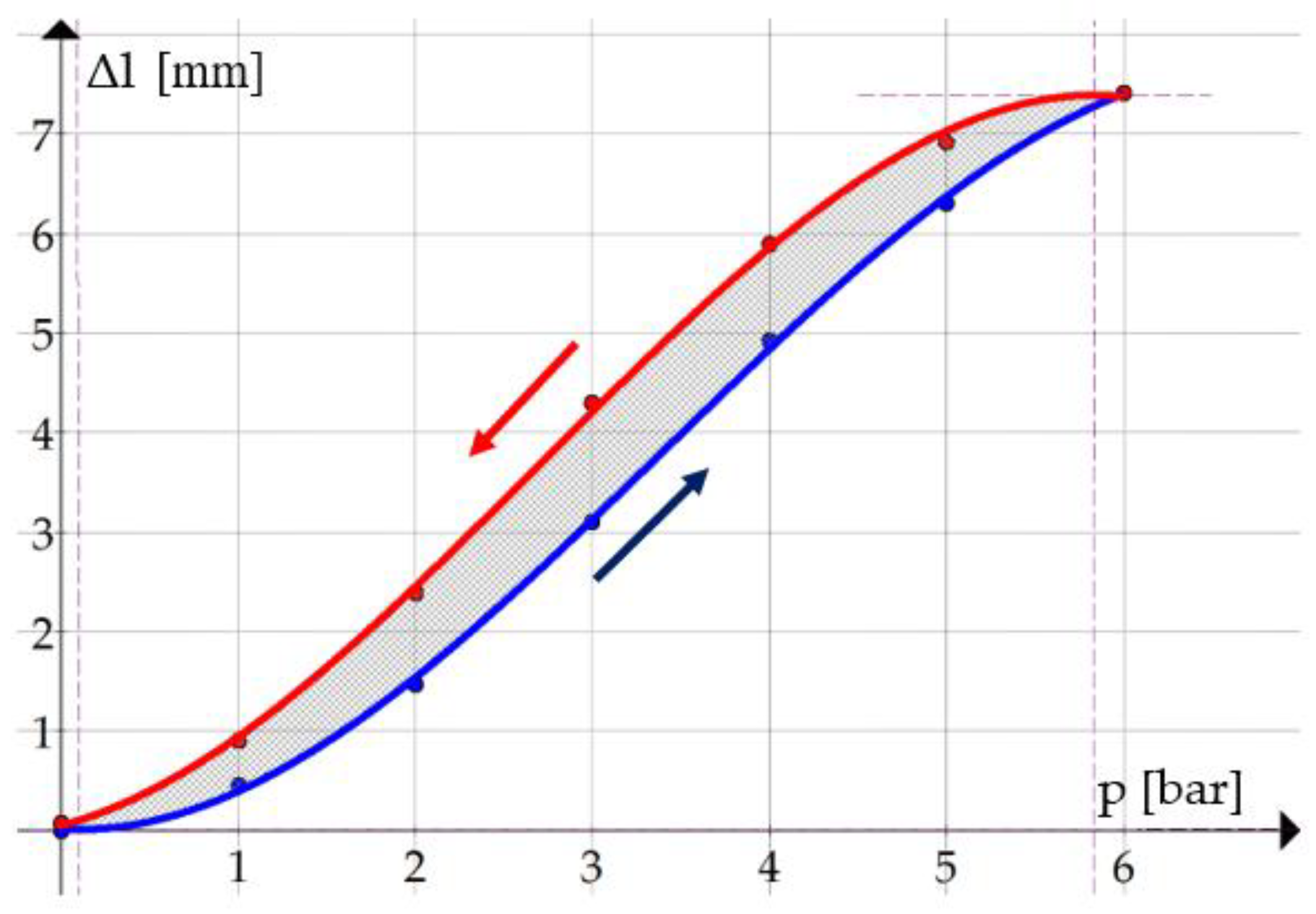
Table 3 shows the data that relate the axial contractions of the muscle to the values of air pressure, and Figure 8 presents the corresponding graph of axial contraction versus pressure. Similarly to the determinations of the muscle diameter values, in this case as well, five inflation/deflation cycles were conducted. After each pressure level was reached, prior to performing the measurement, a minute of rest was allowed in order for the muscle length to stabilize.
In this case as well, the values of the standard deviation show a low measurement uncertainty.
Figure 8 shows that the measured values are greater at deflation than at inflation. The greatest difference of 1.2 mm between the axial contraction of the muscle measured at deflation and inflation, respectively, occurs at a pressure of 3 bar.
The functions that describe the variation of the axial contraction of the pneumatic muscle at inflation and deflation, respectively, at pressures varying from 0 to 6 bar are the following:
For these two functions the coefficients of determination (r2) have the values 0.9996 and 0.9994, respectively, which confirms that they describe the studied phenomenon with high fidelity.
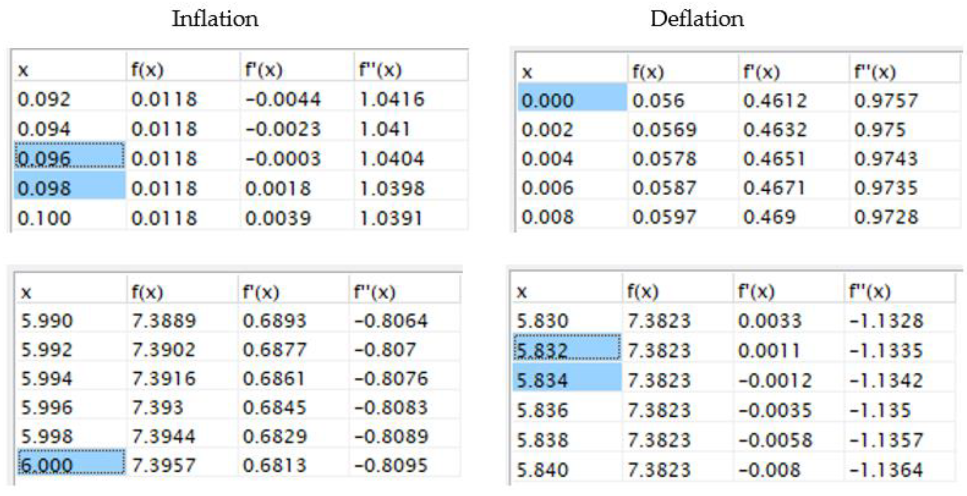
An analysis of the above curves plotted by means of the Graph application reveals that at the inflation of the muscle at a pressure of 0.097 bar the slope of the tangent to the curve is zero. The tangent to the deflation has a zero slope at a pressure of p = 5.833 bar.
These values are considered threshold pressures that mark the onset of the contraction and the relaxation of the muscle, respectively. For the rest of the working pressure values the slope of the tangent to the curve is different from zero, as shown by the data in Figure 9 (the first order derivative of the function is different from zero).
3.3. Evaluation of the Hysteresis of the Forces Developed by the Pneumatic Muscle
Isometric tests were used to measure the forces developed by the pneumatic muscles. In this case, the length of the pneumatic muscle remains unchanged, as it does not carry out external work. Figure 10 shows the experimental set-up used for determining the forces developed by the pneumatic muscle while it was fed air at different pressures.
Five inflation/deflation cycles of the muscle were performed. Upon reaching each pressure level (by 1 bar increments), the force was measured after a minute of rest to allow for the muscle’s form to stabilize.
The force sensor used in the experiments has, according to the Festo catalogue, the following characteristics: measuring range: 0–2 kN; supply voltage: 24 V dc; output signal: 0–10 V.
Table 4 presents the measured values, and Figure 11 shows the variation of the forces developed by the pneumatic muscle while charged with compressed air and discharged, respectively.
The values obtained for the standard deviation reveal a low measurement uncertainty.
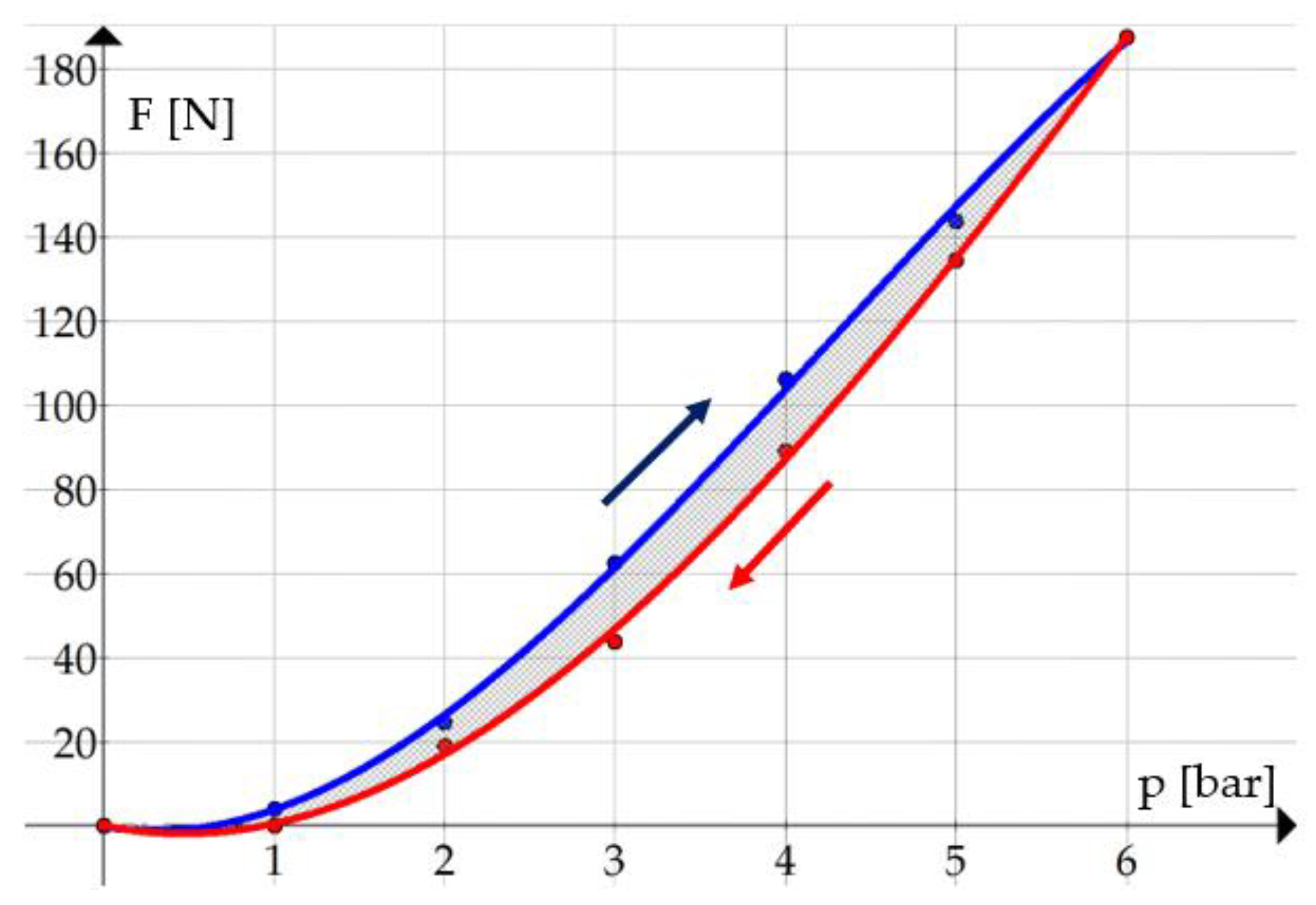
In this case as well, it can be noticed that the forces developed by the pneumatic muscles have different values when fed with compressed air at increasing or decreasing pressures, revealing a hysteretic behaviour. The graph shows that the forces developed by the pneumatic muscle are greater when fed compressed air by increasing pressure.
The equations that describe the variation of the forces versus pressure are as follows:
In the pressure range from 2 to 6 bar the forms of the two curves can be appreciated as linear.
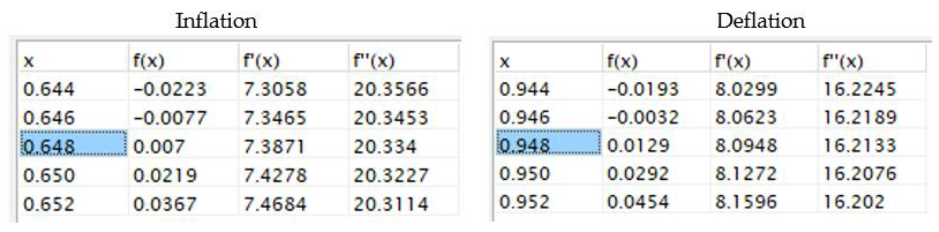
In this case as well, the threshold pressures can be determined up to/from that the pneumatic muscle does not develop any force. For the inflation of the pneumatic muscle, the resulting threshold pressure is of 0.647 bar, meaning that up to this value the muscle does not develop any force. In the case of deflation, the threshold pressure is of 0.947 bar from which downward F = 0 N (Figure 12).
4. Conclusions
Pressurized artificial muscles (PAMs) made from elastomers with aramid fibre insertions represent an innovative solution for applications where positioning precision is not an essential requirement (for example, medical rehabilitation equipment). They can be regarded as an alternative to classical pneumatic cylinders.
The experimental research presented and discussed in the paper was aimed at highlighting the occurrence of the hysteresis phenomenon in a small-size pneumatic muscle manufactured by Festo AG. & Co Esslingen, Germany. By the isotonic and isometric tests conducted for this purpose, the dimensional modifications of this muscle were measured on radial and axial direction, as well as the variation of the developed forces in relation to the pressure of the compressed air fed to the muscles. The hysteresis phenomenon was revealed by the repeated application of charging/discharging cycles of the muscle with compressed air. The variation versus pressure of these dimensional characteristics and of the force are adequately described by third-degree polynomial equations that can be used for configuring the control systems. The obtained equations cannot, however, be generalized, as they are specific to each size of pneumatic muscle. Hence, for each concrete application that uses pneumatic muscles, these polynomial functions have to be determined experimentally.
The conducted measurements led to the identification of threshold pressures, i.e., when the slopes of the tangents to the curves is zero. Their presence is an inconvenience for the utilisation of pneumatic muscles and consequently knowing their values is of the essence.
The conducted experimental research allowed the quantification of the hysteretic behaviour of the studied pneumatic muscle, and the obtained relationships have a high utility potential for the endeavours of improving the controllers for high-performance positioning systems.
Author Contributions
O.F. devised Chapter 1; T.D. and A.D. devised Chapters 2 and 4; O.F. conducted the experiments—Chapter 3. All authors contributed to the writing and revision of the document. All authors have read and agreed to the published version of the manuscript.
Funding
This research received no external funding.
Conflicts of Interest
The authors declare no conflict of interest.
References
- Moon, F.C. The Machines of Leonardo Da Vinci and Franz Reuleaux: Kinematics of Machines from the Renaissance to the 20th Century; Springer Science & Business Media: Dordrecht, The Netherlands, 2007; pp. 268–270. [Google Scholar]
- Palko, A.; Smrček, J. The use of pneumatic artificial muscles in robot construction. Ind. Robot 2011, 38, 11–19. [Google Scholar] [CrossRef]
- Baldwin, H.A. Realizable Models of Muscle Function. In Biomechanics; Bootzin, D., Muffley, H.C., Eds.; Springer: New York, NY, USA, 1969; pp. 139–147. [Google Scholar]
- Morin, A.H. Elastic Diaphragm. U.S. Patent 2,642,091, 16 June 1953. [Google Scholar]
- Yarlott, J.M.; Mass, H. Fluid Actuator. U.S. Patent 3,645,173, 29 February 1972. [Google Scholar]
- Takagi, T.; Sakaguchi, Y. Pneumatic Actuator for Manipulator. U.S. Patent 4,615,260, 7 October 1986. [Google Scholar]
- Kukolj, M. Axially Contractible Actuator. U.S. Patent 4,733,603, 29 March 1988. [Google Scholar]
- Paynter, H.M. Hyperboloid of Revolution Fluid-Driven Tension Actuators and Method of Making. U.S. Patent 4,721,030, 26 January 1988. [Google Scholar]
- Daerden, F. Conception and Realization of Pleated Pneumatic Artificial Muscles and Their Use as Compliant Actuation Elements. Ph.D. Thesis, Vrije Universiteit Brussels, Brussels, Belgium, 1999. [Google Scholar]
- Pneumatic Artificial Muscles. Available online: https://en.wikipedia.org/wiki/Pneumatic_artificial_muscles (accessed on 3 September 2020).
- Chou, C.-P.; Hannaford, B. Static and dynamic characteristics of McKibben pneumatic artificial muscles. In Proceedings of the 1994 IEEE International Conference on Robotics and Automation, San Diego, CA, USA, 8–13 May 1994; pp. 281–286. [Google Scholar]
- Caldwell, D.G.; Tsagarakis, N.; Medrano-Cerda, G.A. Bio-mimetic actuators: Polymeric Pseudo Muscular Actuators and pneumatic Muscle Actuators for biological emulation. Mechatronics 2000, 10, 499–530. [Google Scholar] [CrossRef]
- Mirvakili, S.M.; Sim, D.; Hunter, I.W.; Langer, R. Actuation of untethered pneumatic artificial muscles and soft robots using magnetically induced liquid-to-gas phase transitions. Sci. Robot. 2020, 5, 1–9. [Google Scholar] [CrossRef]
- Minh, T.V.; Tjahjowidodo, T.; Ramon, H.; Van Brussel, H. Control of a pneumatic artificial muscle (PAM) with model-based hysteresis compensation. In Proceedings of the IEEE/ASME International Conference on Advanced Intelligent Mechatronics, Singapore, 14–17 July 2009; pp. 1082–1087. [Google Scholar]
- Yeh, T.J.; Wu, M.-J.; Lu, T.-J.; Wu, F.-K.; Huang, C.-R. Control of McKibben pneumatic muscles for a power-assist, lower-limb orthosis. Mechatronics 2010, 20, 686–697. [Google Scholar] [CrossRef]
- Van Damme, M.; Beyl, P.; Vanderborght, B.; Van Ham, R.; Vanderniepen, I.; Versluys, R.; Daerden, F.; Lefeber, D. Modeling Hysteresis in Pleated Pneumatic Artificial Muscles. In Proceedings of the 2008 IEEE Conference on Robotics, Automation and Mechatronics, Chengdu, China, 21–24 September 2008; pp. 471–476. [Google Scholar]
- Zang, X.; Liu, Y.; Heng, S.; Lin, Z.; Zhao, J. Position control of a single pneumatic artificial muscle with hysteresis compensation based on modified Prandtl-Ishlinskii model. Biomed. Mater. Eng. 2017, 28, 131–140. [Google Scholar] [CrossRef] [PubMed]
- Xie, S.; Liu, H.; Wang, Y. A method for the length-pressure hysteresis modeling of pneumatic artificial muscles. Sci. China Technol. Sci. 2020, 63, 829–837. [Google Scholar] [CrossRef]
- Zhao, J.; Zhong, J.; Fan, J. Position Control of a Pneumatic Muscle Actuator Using RBF Neural Network Tuned PID Controller. Math. Probl. Eng. 2015. [Google Scholar] [CrossRef]
- Zhu, L.; Shi, X.; Chen, Z.; Zhang, H.; Xiong, C. Adaptive Servomechanism of Pneumatic Muscle Actuators With Uncertainties. IEEE Transac. Ind. Electron. 2017, 64, 3329–3337. [Google Scholar] [CrossRef]
- Schreiber, F.; Sklyarenko, Y.; Runge, G.; Schumacher, W. Model-based controller design for antagonistic pairs of fluidic muscles in manipulator motion control. In Proceedings of the IEEE 17th International Conference on Methods and Models in Automation and Robotics (MMAR), Miedzyzdrojie, Poland, 27–30 August 2012; pp. 499–504. [Google Scholar]
- Zhang, Z. Modeling, Analysis, and Experiments of Inter Fiber Yarn Compaction Effects in Braided Composite Actuators. Ph.D. Thesis, Virginia Polytechnic Institute, Blacksburg, VA, USA, 2012. [Google Scholar]
- Kydoniefs, A.D. Finite Axisymmetric Deformations of An Initially Cylindrical Membrane Reinforced with Inextensible Cords. Q. J. Mech. Appl. Math. 1970, 23, 481–488. [Google Scholar] [CrossRef]
- Matsikoudi-Iliopoulou, M. Finite axisymmetric deformations with torsion of an initially cylindrical membrane reinforced with one family inextensible cords. Int. J. Eng. Sci. 1987, 25, 673–680. [Google Scholar] [CrossRef]
- Liu, W.; Rahn, C.R. Fiber-reinforced membrane models of McKibben actuators. Transac. ASME J. Appl. Mech. 2003, 70, 853–859. [Google Scholar] [CrossRef]
- Tondu, B. Modelling of the McKibben artificial muscle: A review. J. Intell. Mater. Syst. Struct. 2012, 23, 225–253. [Google Scholar] [CrossRef]
- Shadow Robot Company. Shadow 30 mm Air Muscle-Specification. Available online: https://www.shadowrobot.com/downloads/datasheet_30mm_sam.pdf (accessed on 14 June 2020).
- Fluidic Muscle DMSP/MAS, Festo Product Flyer. 2015. Available online: https://www.festo.com/net/SupportPortal/Files/340809/Muskel_Flyer_en.pdf (accessed on 14 June 2020).
- Petre, I.; Deaconescu, A.; Rogozea, L.; Deaconescu, T. Orthopaedic Rehabilitation Device Actuated with Pneumatic Muscles. Int. J. Adv. Robot. Syst. 2014, 11, 1–8. [Google Scholar] [CrossRef] [Green Version]
- Bergemann, D.; Lorenz, B.; Thallemer, A. Actuating means. U.S. Patent US6349746B1, 26 February 2002. [Google Scholar]
- Festo: Precisely to the Point: Membrane Technology. 2014. Available online: https://www.festo.com/cms/en_corp/14047.htm (accessed on 15 June 2020).
- Santora, M. Membrane Technology Flexes Its Muscle-Precisely, Pneumatic Tips, 2015. Available online: http://www.pneumatictips.com/3970/2015/05/featured/membrane-technology-flexes-its-muscle-precisely/ (accessed on 15 June 2020).
- Vo-Minh, T.; Tjahjowidodo, T.; Ramon, H.; Van Brussel, H. A New Approach to Modeling Hysteresis in a Pneumatic Artificial Muscle Using the Maxwell-Slip Model. IEEE/ASME Transact. Mechatron. 2011, 16, 177–186. [Google Scholar] [CrossRef]
- Deaconescu, T.; Deaconescu, A. Study concerning the Hysteresis of Pneumatic Muscles. Appl. Mech. Mater. 2016, 841, 209–214. [Google Scholar] [CrossRef]
Figure 1.
Construction and structure of a Festo pneumatic muscle.

Figure 2.
Layout of the aramid fibre mesh.

Figure 3.
Model of the thin-walled tube.

Figure 4.
Measuring the radial deformations of the pneumatic muscle.

Figure 5.
Evolution of the pneumatic muscle diameter versus air pressure.

Figure 6.
Evaluation of the slope of the tangent to the curve defined by Equation (4).

Figure 7.
Experimental set-up for determining the hysteresis of muscle axial displacement.

Figure 8.
Evolution of the pneumatic muscle axial contraction versus air pressure.

Figure 9.
Evaluation of the slope of the tangent to the curves defined by Equations (5) and (6).

Figure 10.
Measuring the forces developed by the pneumatic muscle.

Figure 11.
Variation of the forces developed by the pneumatic muscle versus pressure.

Figure 12.
Evaluation of the slopes of the tangents to the curves defined by Equations (7) and (8).


Table 1.
Characteristics of the materials of a pneumatic muscle.
| Material | Density | Tensile Strength at Break | Elongation at Break | Young’s Modulus |
|---|---|---|---|---|
| [g/cm3] | [MPa] | [%] | [MPa] | |
| Elastic tube (chloroprene rubber) | 1.23 | 19 | 800 | 1.65 |
| Fibre insertions (aramid fibres) | 1.43 | 2757 | 3.6 | 70500 |
Table 2.
Muscle diameters for zero external load.
| Pressure [bar] | Inflation/Deflation Cycle | Arithmetic Mean | Standard Deviation | Theoretical Diameter Calculated by Equation (2) [Mm] | |||||
|---|---|---|---|---|---|---|---|---|---|
| 1 | 2 | 3 | 4 | 5 | |||||
| Inflation | 0 | 13.65 | 13.64 | 13.69 | 13.68 | 13.69 | 13.67 | 0.02345 | 13.5 |
| 1 | 14.75 | 14.77 | 14.74 | 14.77 | 14.77 | 14.76 | 0.01414 | 14.76 | |
| 2 | 16.02 | 16.04 | 16.04 | 16.03 | 16.02 | 16.03 | 0.01 | 16.03 | |
| 3 | 17.29 | 17.3 | 17.31 | 17.27 | 17.28 | 17.29 | 0.01581 | 17.29 | |
| 4 | 18.54 | 18.57 | 18.58 | 18.56 | 18.55 | 18.56 | 0.01581 | 18.56 | |
| 5 | 19.8 | 19.81 | 19.83 | 19.83 | 19.83 | 19.82 | 0.01414 | 19.82 | |
| 6 | 21.08 | 21.06 | 21.1 | 21.09 | 21.07 | 21.08 | 0.01581 | 21.08 | |
| Deflation | 5 | 20.19 | 20.21 | 20.23 | 20.2 | 20.22 | 20.21 | 0.01581 | 19.82 |
| 4 | 19.3 | 19.33 | 19.3 | 19.31 | 19.31 | 19.31 | 0.01224 | 18.56 | |
| 3 | 18.25 | 18.27 | 18.25 | 18.29 | 18.29 | 18.27 | 0.02 | 17.29 | |
| 2 | 16.14 | 16.1 | 16.1 | 16.13 | 16.13 | 16.12 | 0.0187 | 16.03 | |
| 1 | 14.85 | 14.83 | 14.84 | 14.8 | 14.83 | 14.83 | 0.0187 | 14.76 | |
| 0 | 13.72 | 13.71 | 13.71 | 13.71 | 13.75 | 13.72 | 0.01732 | 13.5 | |
Table 3.
Axial contraction of the pneumatic muscle for zero external load.
| Pressure [bar] | Inflation/Deflation Cycle | Arithmetic Mean | Standard Deviation | |||||
|---|---|---|---|---|---|---|---|---|
| 1 | 2 | 3 | 4 | 5 | ||||
| Inflation | 0 | 0 | 0 | 0 | 0 | 0 | 0 | 0 |
| 1 | 0.45 | 0.44 | 0.48 | 0.48 | 0.45 | 0.46 | 0.0187 | |
| 2 | 1.48 | 1.46 | 1.44 | 1.48 | 1.48 | 1.468 | 0.01788 | |
| 3 | 3.09 | 3.08 | 3.12 | 3.11 | 3.1 | 3.1 | 0.01581 | |
| 4 | 4.92 | 4.9 | 4.93 | 4.93 | 4.92 | 4.92 | 0.01224 | |
| 5 | 6.28 | 6.3 | 6.28 | 6.32 | 6.32 | 6.3 | 0.02 | |
| 6 | 7.39 | 7.4 | 7.41 | 7.43 | 7.42 | 7.41 | 0.01581 | |
| Deflation | 5 | 6.89 | 6.9 | 6.9 | 6.93 | 6.93 | 6.91 | 0.0187 |
| 4 | 5.88 | 5.89 | 5.88 | 5.89 | 5.91 | 5.89 | 0.01224 | |
| 3 | 4.28 | 4.31 | 4.3 | 4.31 | 4.3 | 4.3 | 0.01224 | |
| 2 | 2.37 | 2.4 | 2.41 | 2.39 | 2.38 | 2.39 | 0.01581 | |
| 1 | 0.9 | 0.89 | 0.94 | 0.91 | 0.91 | 0.91 | 0.0187 | |
| 0 | 0.07 | 0.08 | 0.09 | 0.08 | 0.08 | 0.08 | 0.00707 | |
Table 4.
Correspondence between the developed force and the charging pressure.
| Pressure [bar] | Inflation/Deflation Cycle | Arithmetic Mean | Standard Deviation | |||||
|---|---|---|---|---|---|---|---|---|
| 1 | 2 | 3 | 4 | 5 | ||||
| Inflation | 0 | 0 | 0 | 0 | 0 | 0 | 0 | 0 |
| 1 | 3.84 | 3.86 | 3.85 | 3.91 | 3.89 | 3.87 | 0.02915 | |
| 2 | 24.59 | 24.6 | 24.62 | 24.62 | 24.62 | 24.61 | 0.01414 | |
| 3 | 62.38 | 62.4 | 62.4 | 62.43 | 62.39 | 62.4 | 0.0187 | |
| 4 | 105.9 | 105.9 | 106.2 | 106.1 | 105.9 | 106 | 0.14142 | |
| 5 | 143.7 | 143.8 | 143.8 | 143.9 | 143.8 | 143.8 | 0.07071 | |
| 6 | 187.4 | 187.3 | 187.6 | 187.4 | 187.3 | 187.4 | 0.12247 | |
| Deflation | 5 | 134.1 | 134.4 | 134.4 | 134.4 | 134.2 | 134.3 | 0.14142 |
| 4 | 88.92 | 88.95 | 88.97 | 88.96 | 88.95 | 88.95 | 0.01870 | |
| 3 | 43.5 | 43.4 | 43.6 | 43.8 | 43.7 | 43.6 | 0.15811 | |
| 2 | 18.99 | 18.98 | 18.99 | 18.98 | 19.01 | 18.99 | 0.01224 | |
| 1 | 0.09 | 0.09 | 0.1 | 0.12 | 0.1 | 0.1 | 0.01224 | |
| 0 | 0 | 0 | 0 | 0 | 0 | 0 | 0 | |
© 2020 by the authors. Licensee MDPI, Basel, Switzerland. This article is an open access article distributed under the terms and conditions of the Creative Commons Attribution (CC BY) license (http://creativecommons.org/licenses/by/4.0/).
Share and Cite
MDPI and ACS Style
Filip, O.; Deaconescu, A.; Deaconescu, T. Experimental Research on the Hysteretic Behaviour of Pressurized Artificial Muscles Made from Elastomers with Aramid Fibre Insertions. Actuators 2020, 9, 83. https://doi.org/10.3390/act9030083
AMA Style
Filip O, Deaconescu A, Deaconescu T. Experimental Research on the Hysteretic Behaviour of Pressurized Artificial Muscles Made from Elastomers with Aramid Fibre Insertions. Actuators. 2020; 9(3):83. https://doi.org/10.3390/act9030083
Chicago/Turabian StyleFilip, Ovidiu, Andrea Deaconescu, and Tudor Deaconescu. 2020. "Experimental Research on the Hysteretic Behaviour of Pressurized Artificial Muscles Made from Elastomers with Aramid Fibre Insertions" Actuators 9, no. 3: 83. https://doi.org/10.3390/act9030083
Note that from the first issue of 2016, this journal uses article numbers instead of page numbers. See further details here.