

A Self–Tuning Intelligent Controller for a Smart Actuation Mechanism of a Morphing Wing Based on Shape Memory Alloys


1
École de Technologie Supérieure in Montréal, LARCASE—Laboratory of Active Controls, Aeroservoelasticity and Avionics, Montreal, QC H3C 1K3, Canada
2
Faculty of Aerospace Engineering, University Politehnica of Bucharest, 060042 Bucharest, Romania
*
Author to whom correspondence should be addressed.
Actuators 2023, 12(9), 350; https://doi.org/10.3390/act12090350
Submission received: 24 April 2023
/
Revised: 13 August 2023
/
Accepted: 29 August 2023
/
Published: 31 August 2023
(This article belongs to the Special Issue Actuators in 2022)
Abstract
:The paper exposes some of the results obtained in a major research project related to the design, development, and experimental testing of a morphing wing demonstrator, with the main focus on the development of the automatic control of the actuation system, on its integration into the experimental developed morphing wing system, and on the gain related to the extension of the laminar flow over the wing upper surface when it was morphed based on this control system. The project was a multidisciplinary one, being realized in collaboration between several Canadian research teams coming from universities, research institutes, and industrial entities. The project’s general aim was to reduce the operating costs for the new generation of aircraft via fuel economy in flight and also to improve aircraft performance, expand its flight envelope, replace conventional control surfaces, reduce drag to improve range, and reduce vibrations and flutter. In this regard, the research team realized theoretical studies, accompanied by the development and wind tunnel experimental testing of a rectangular wing model equipped with a morphing skin, electrical smart actuators, and pressure sensors. The wing model was designed to be actively controlled so as to change its shape and produce the expansion of laminar flow on its upper surface. The actuation mechanism used to change the wing shape by morphing its flexible upper surface (manufactured from composite materials) is based on Shape Memory Alloys (SMA) actuators. Shown here are the smart mechanism used to actuate the wing’s upper surface, the design of the intelligent actuation control concept, which uses a self–tuning fuzzy logic Proportional–Integral–Derivative plus conventional On–Off controller, and some of the results provided by the wind tunnel experimental testing of the model equipped with the intelligent controlled actuation system. The control mechanism uses two fuzzy logic controllers, one used as the main controller and the other one as the tuning controller, having the role of adjusting (to tune) the coefficients involved in the operation of the main controller. The control system also took into account the physical limitations of the SMA actuators, including a software protection section for the SMA wires, implemented by using a temperature limiter and by saturating the electrical current powering the actuators. The On–Off component of the integrated controller deactivates or activates the heating phase of the SMA wires, a situation when the actuator passes into the cooling phase or is controlled by the Self–Tuning Fuzzy Logic Controller.
1. Introduction
The last two decades have proven to be the most prolific from the point of view of technological progress in all fields of activity, but especially in the area of top industries, which also includes the aerospace industry. This explosive technological advance sent to the experimental area of aviation a multitude of concepts that a few decades ago seemed dedicated only to the theory. The important advances in the area of the aerospace industry were largely generated due to the need to solve some increasingly acute problems, noticed both at the level of the companies producing aircraft and also at the level of those who exploit them. From this point of view, the development of new aeronautical systems that protect the environment is a worldwide desire, a desire that is somehow corroborated by the acute need of the aviation industry to reduce total operating costs, which is an important component of the costs related to fuel. The increase in fuel costs leads to a decrease in the aerospace industry activity, thus stimulating the research activity to find methods and technological solutions that involve achieving fuel economy. A direction of research that is more and more approached is that the reduction in fuel consumption is pursued by reducing the drag force of aircraft during flight, which is directly related to the airflow type around the aircraft body. The drag force magnitude for a body included in a fluid that flows is influenced by the laminarity of the flow around the body, and it is smaller, the larger the laminar flow area is, that is, the position of the transition area between laminar and turbulent flows is closer to the trailing edge of the aerodynamic surface of the body. From another perspective, if we refer to an aircraft wing, this transition between laminar and turbulent depends strongly by the wing airfoil shape. Therefore, a way to extend the laminar flow over the wing is to change the wing shape, with a direct implication in the decrease in the drag force. In this trend, worldwide industrial entities have started a series of initiatives aiming at the acceleration of technological progress at the level of aeronautical systems by increasing the collaboration level with the research entities but also with the university area. On the other hand, many studies with outstanding results, both theoretical and experimental, were carried out only at the level of university research teams.
Such an initiative is the AWiTech (Adaptive Wing Technologies) project started in 2002 by DLR Institutes of Structural Mechanics and Design Aerodynamics and by the Institute of Aeroelasticity of the University of Aachen, pursuing the design of a wing for a transport aircraft with an aerodynamically optimized shape for large parts of the cruise flight [1]. In 2003, DARPA, in collaboration with the Air Force Research Laboratory (AFRL), proposed the Morphing Aircraft Structure (MAS) program. It aimed at the development of active morphing wing structures with variable shapes and of morphing flight vehicles able to change their geometry in flight to obtain better aerodynamic performance not possible with conventional aircraft structures [2,3]. In the laboratory of Texas A&M University–Kingsville, has been experimented a simple way to realize a morphing wing by using elastomeric composites as skins and actuators [4]. The researchers from the University of Maryland performed an analysis related to the potential application of the pneumatic artificial muscles they developed in the morphing wing field; two actuation schemes are targeted: (i) a morphing cell for a wing section and (ii) trailing edge flaps for wings or rotorcraft blades [5]. In the SMorph—Smart Aircraft Morphing Technologies project, a collaborative research project between three university partners from the UK, Portugal, and Italy, the team studied several morphing aeroelastic structures [6]. In the SmartLED project, DLR developed and tested, in 2009, a smart leading–edge device for commercial transportation aircraft in partnership with Airbus, EADS–IW, and EADS–MAS [7,8]. Between September 2011 and February 2015, the EU funded the NOVEMOR project, coordinated by Instituto Superior Tecnico from Portugal, in collaboration with seven other partners from Italy, the UK, Sweden, Germany, South Africa, and Brazil. The project proposed, among others, to provide new concepts and solutions for morphing wings in order to improve the performance characteristics in terms of drag, loads, weight, and noise impact reduction [9]. Airbus operations GMBH, as coordinator, together with another 68 partners, initiated and realized, between 2011 and 2015, the Smart Intelligent Aircraft Structures (SARISTU) project, were aircraft’s weight and operational cost reductions as well as the improvement in the flight profile specific aerodynamic performance were addressed by integration of various smart structural concepts [10,11,12]. The CHANGE project, funded by the EU between 2012 and 2015 and developed in collaboration between partners from Portugal, Germany, the United Kingdom, Turkey, and the Netherlands, proposed to investigate and to create a novel morphing system that integrates up to four different morphing mechanisms into a single wing. As communicated results, the research team proposed six technologies and tested five in wind tunnels, but also combined several systems on a few morphing wings equipping UAV systems [13]. Within the Joint European Initiative on Green Regional Aircraft frame, ONERA researchers, in collaboration with Alenia (now Leonardo), studied the gust load alleviation for different control laws used for control surface deflection [14]. In the same project, CIRA, in cooperation with the University of Naples, tested a technology based on Shape Memory Alloy (SMA) to actuate various morphing wing architectures [15,16]. In 2014, during the Adaptive Compliant Trailing Edge (ACTE) project, NASA and the U.S. Air Force Research Laboratory tested in flight flexible trailing–edge wing flaps built by FlexSys, Inc. to evaluate their viability in the reduction in the takeoffs and landings noise, but also in the improvement in aerodynamic efficiency [17]. A collaborative team, with researchers from three Italian, Spanish, and Australian universities, developed and experimentally tested a new wing morphing concept with the aim of comparing its performance with the conventional wing–flap configuration [18]. In China, at the School of Aeronautical Science and Engineering, Beihang University, Beijing, the structural design and testing of an adaptive variable camber wing were realized in collaboration with researchers from the University of Leeds, UK [19]. Various studies related to this concept were also realized by researchers from the Military Technical Academy in Romania [20,21,22]. The Indian Institute of Technology Madras studied, from structural and aerodynamic perspectives, various wing configurations for morphing [23,24]. In 2017, the EU started the project Smart Morphing and Sensing (SMS), coordinated by Institut National Polytechnique de Toulouse from France and realized in collaboration with ten other partners from France, Italy, Greece, Poland, Germany, and Switzerland. The project tested the new technologies related to electro–active actuators and sensors in morphing applications to increase aerodynamic efficiency and attenuate vibrations and noise [25]. A research team from the French Aerospace Lab—ONERA in France is actively involved in the theoretical and experimental study of morphing wing applications, part of them developed under major EU–funded projects [26,27,28]. In Japan, many studies related to the design, manufacturing, and experimental testing of the morphing wings were developed by the Japan Aerospace Exploration Agency and by the University of Tokyo; a collaborative study between the two entities was concretized in the development and testing of variable geometry morphing airfoil using corrugated structures [29]. The University of Washington Aeronautical Laboratory (UWAL) has designed, developed, and wind tunnel tested a flexible wing configuration with a variable camber continuous trailing edge flap, with three chordwise camber segments and five spanwise flap sections [30]. With the aim to investigate the feasibility of developing, manufacturing, and testing a multi–objective technology (integration of smart sensing, smart actuation, and smart control methodologies) for smart structures with aeronautical applications, the Delft University of Technology realized the SmartX project [31]. A collaboration between the Technical University of Denmark and the Italian Aerospace Research Centre—CIRA, in the Interactive, Non–linear, High–Resolution Topology Optimization (InnoTop) project (2017–2023), which aims, between various applications, to develop interactive and high–resolution design tools used for the design of airplane structures with significant weight savings, reduced costs, and lower energy consumption, provided a systematic topology optimization approach for simultaneously designing the morphing functionality and actuation in three–dimensional wing structures [32].
The literature also reveals a series of review articles in the field, analyzing the application of morphing structures in aviation [2,33,34,35,36,37,38,39,40]. The analysis conducted to a logical conclusion: to develop an experimental morphing wing model, the control system, the actuation mechanism used to morph the structure, and the flexible skin design should meet the morphing requirements of the wing and should be able to work together as a whole in all the required flight conditions. Therefore, there are still many challenges in the used technologies at the level of the used materials, actuation systems, and control systems. The intrinsic properties of the materials and structures impose the deformation limits in the morphing process. The already developed morphing wing structures used various types of flexible materials, moving mechanisms, and corrugated structure skins, but, nevertheless, those are contradictory in weight, load capacity, and deformation capacity as a whole. The flexible materials are characterized by a high degree of deformation and air tightness but are seriously limited at the level of the load capacity, while the moving mechanisms can be highly loaded but have serious problems with the air tightness and when it is necessary to provide a smooth surface. As a consequence, there are still open issues related to the development of high–quality materials and structures to be used in morphing aircraft applications. At the level of the automatic control systems used in these kinds of applications, from the theoretical point of view, any control method can be used, but, having in mind the complexity of the controlled systems, there are many limitations, especially when the linear control methods are used. The controlled structures usually have a strongly nonlinear character; therefore, with the linear control methods, it is difficult to obtain a high–performance controlled system at the global level, covering the entire envelope of system operation. As a consequence, in these situations, it is recommended to use the control systems based on nonlinear methods, but the obtained results in terms of control accuracy and robustness are highly influenced by the controlled dynamic model. As a suitable and more accurate alternative, the literature proposes the using of artificial intelligence–based control methods for these kinds of applications [2,33,34,35,36,37,38,39,40].
In this context, in a major Canadian research project related to morphing wing, which was financed by the CRIAQ (Consortium for Research and Innovation in Aerospace in Quebec), our research team from the Ecole de Technologie Supérieure (ETS), Research Laboratory in Active Controls, Avionics and Aeroservoelasticity (LARCASE), Montréal, Canada, designed, optimized, manufactured, and tested a morphing wing experimental model, actuated by using with SMA (Shape Memory Alloys) wires. The project, called CRIAQ 7.1— Laminar flow improvement on an aeroelastic research wing, was a multidisciplinary one, being realized in a collaboration between several Canadian research teams coming from universities, research institutes and industrial entities, such as ETS in Montreal (two research teams coming from two laboratories in ETS: LAMSI (Laboratory of Memory Alloys and Intelligent Systems) and LARCASE), École Polytechnique de Montréal, Institute for Aerospace Research from National Research Council of Canada (NRC–IAR), Bombardier Aerospace and Thales Canada. The research team realized theoretical studies, accompanied by the development and wind tunnel experimental testing of a rectangular wing model equipped with a morphing skin, electrical smart actuators, and pressure sensors. The wing model was designed to be actively controlled so as to change its shape and produce the expansion of laminar flow on its upper surface. The actuation mechanism used to change the wing shape by morphing its flexible upper surface (manufactured from composite materials) is based on Shape Memory Alloy actuators.
The results shown here are obtained during this project, the paper exposing the smart mechanism used to actuate the upper surface of the wing, the design of the intelligent actuation control concept, which uses a self–tuning fuzzy logic Proportional–Integral–Derivative plus conventional On–Off controller, and the results obtained during the wind tunnel testing of the morphing wing equipped with the intelligent controlled actuation system. Two fuzzy inference systems were designed and implemented in the self–tuning fuzzy logic controller, both of them using s–functions, π–functions, and z–functions as shapes for the included membership functions. The MATLAB/Simulink software has been used in the design, simulation, and tuning of the control system for the actuation mechanism, while its experimental testing was conducted in the wind tunnel tests simultaneously with the experimental evaluation of the aerodynamic part of the morphing wing model. The main contributions of the paper are the development of the control system for the SMA actuation lines, its integration into the experimental developed morphing wing system, and the gain related to the extension of the laminar flow over the wing upper surface when it was morphed based on this control system. Our research team developed and tested various control systems for the actuation mechanism used in this project. During the tests, the team observed that the presented control system allows the actuation lines to work at lower temperatures in comparison with other situations where the actuation lines are similarly loaded but are controlled with other control systems. Additionally, the team concluded that another advantage of this control system is the reduction in the oscillation amplitude of the controlled actuation distance around the desired position, seen as a combination of the noise and the controlled cooling/heating and heating/cooling switch.
This paper is organized as follows: Section 2 briefly presents the morphing wing project context and describes the architecture of the actuation mechanism used to morph the wing; Section 3 presents the general architecture of the actuation lines control system and the operation mechanisms behind the On–Off plus Self–Tuning Fuzzy Logic integrated controller; Section 4 exposes the experimental results obtained during the wind tunnel testing of the actuation lines control system, while Section 5 is dedicated to the conclusions, highlighting the analysis and the interpretation of the numerical end experimentally results obtained during the design, implementation, and validation phases of the control system.
2. Morphing Wing Project Context and Description of the Actuation Mechanism
Very complex and categorized by the scientific community as inter and multidisciplinary studies, theoretical and experimental studies related to morphing wings continue to “push” the knowledge to the extreme limits of the general technologies, but also of mathematics, physics, and chemistry, as fundamental sciences. The analysis of the worldwide already developed systems in the field, correlated with the general needs imposed by such an application, leads to the conclusion that such studies require advanced knowledge in the following disciplines: aerodynamics and computational fluid dynamics, aero–elasticity, automatic control, smart materials and special materials, actuation systems (smart and classical, with a high miniaturization degree and with outstanding performance in terms of power/weight or power/volume ratio), wind tunnel and flight testing, instrumentation and signal detection by using the latest miniaturized sensors, data acquisition and signal processing, high computer–time calculations—these signals include high–frequency components requiring very high computing processing speeds that raise serious problems for the existing computing technology.
Inter and multidisciplinary nature of the project required the formation of a collaborative research team capable of satisfying all the research directions involved in the project development. Therefore, the involved research teams solved various tasks during the project development, depending on the scientific background of their researchers. The team from the Shape Memory Alloys and Intelligent Systems Laboratory (LAMSI) in ETS designed and manufactured the actuators used to morph the wing but also designed the internal structure of the morphing wing experimental model. Starting from a reference airfoil, the research team from the École Polytechnique performed some optimization studies for various flow conditions, based on CFD codes, to find the configuration of the airfoil (associated with each flow condition) providing, from the aerodynamic point of view, the best position along the chord of the transition point between the laminar and turbulent flow. Our team from LARCASE realized the integration of the whole morphing wing system, including the software and the hardware developed components, but also designed, tested, and validated, numerically and experimentally, the control system and the instrumentation used to monitor the experimental model. The NRC–IAR team, which specialized in wind tunnel tests, was the one that, among other activities, organized, carried out, and supervised all the wind tunnel tests.
As a starting point for the aerodynamics part of the research project, the team used a WTEA–TE1 reference airfoil. Based on this airfoil, has been designed and manufactured a rectangular morphing wing experimental model, with 0.5 m of chord and 0.9 m of span. The wing model incorporated two parts (Figure 1): (i) a rigid one, which was built in aluminum, with the role to sustain all the forces acting during the actuation and wind tunnel tests; and (ii) a flexible one, which is the upper surface of the model consisting in a flexible skin made from a composite material which included a resin matrix, Kevlar fibers, and layers of carbon. The NRC–IAR team designed and manufactured the rigid part of the model, taking into account the need for space to put inside the wing the actuation system and the instrumentation parts [41].
The flexible skin on the upper surface was manufactured in a four–ply laminate structure in a polymer matrix: two inner plies with unidirectional carbon fibers and two outer plies with hybrid Kevlar®/carbon fibers. Having in mind that the designed morphing wing needed to change its shape as a function of different flow conditions, the skin required high flexibility in the chordwise direction, and, as a consequence, the design team chose to use the hybrid Kevlar®/carbon fibers on this direction. Additionally, because in the spanwise direction, the design requirements imposed to have low elasticity, considering the chosen way to actuate the wing shape, the unidirectional carbon fibers were used here. It resulted in a flexible skin with 1.3 mm thickness and a total Young modulus of 60 GPa. Additionally, the skin properties revealed a 0.12 Poisson ratio for carbon/Kevlar® hybrid fibers and 0.25 for unidirectional carbon fibers [42,43]. In this architecture, the wing model was able to change its shape in order to move the position of transition from laminar to turbulent flow by using some smart actuators, which were mounted on two actuation lines in real–time and controlled by an active controller. The LARCASE team instrumented the model, the first step being the mounting of 32 pressure sensors on the flexible skin (16 between them based on optical phenomena (Fiber Bragg Grating (FBG) based high–accuracy pressure sensors) and 16 microphone type sensors, manufactured by Kulite). The pressure sensors were installed on two lines, disposed at an angle of 15 degrees, as in Figure 2, and were used to estimate the position along the chord of the transition between laminar and turbulent flow during the wind tunnel testing of the model [44].
To fulfill the aerodynamic objective of the project, at the first step of the studies, the researchers from the École Polytechnique performed some optimization studies by using CFD codes starting from the reference airfoil of the wing. The optimization aimed at determining the shape of the airfoil offering the best position along the chord (near the trailing edge) of the transition between laminar and turbulent flow associated with a flow condition identified in terms of Mach number and angle of attack.
During this optimization were performed studies for 35 different flow conditions, obtained combining five Mach numbers (between 0.2 and 0.3, with a 0.025 step) and seven attack angles (between -1° and 2°, with a 0.5° step) [45]. The obtained optimized airfoil shapes provided the necessary initial data (Figure 3) to start the design of the actuation system. The laminar WTEA–TE1 reference airfoil used as a starting point for the aerodynamics part of the research project was provided by the NRC–IAR team [46,47]. Additionally, the obtained optimized shapes were stored in a computer database and further used during the project development.
To achieve each of the 35 optimized airfoils, the flexible skin needs to change its shape by using the actuation system, which acts in two points along the airfoil chord (at 25.3% of the chord and at 47.6% of the chord) (Figure 3).
The actuators include two oblique cams with sliding rods converting the horizontal displacement in the spanwise direction (x direction) into a vertical displacement, following a direction perpendicular to the chord (z direction) (Figure 4). The cam converts the displacement in the horizontal plane of each actuator into a displacement in the vertical plane at a rate of 3:1, i.e., x/z = 3. Therefore, we can define the cam factor with the relation cf = z/x = 1/3. The correlation between the 35 optimized airfoil shapes, the actuation lines position along the chord, and the reference airfoil shape provided a maximum vertical displacement of the rods (in the actuation lines positions) of approximately 8 mm, which means that a 24 mm maximum horizontal distance needs to be actuated.
The horizontal positions of the two actuators are established under the mechanical equilibrium between the forces developed by the SMA wires, acting on the sliding rods, and the force developed by the gas springs pulling the sliding rods in the same direction but in a reverse sense. Additionally, the gas springs have the mission to compensate for the effect produced by the aerodynamic forces that act over the model’s upper surface when the air flows around the wing and the SMA wires are not activated. The SMA wires used in our morphing wing application were made of nickel—titanium and had the property to contract like muscles when electrically driven. This property of shortening or flexing characterizes some alloys which, at a specified temperature, dynamically change their internal structure. These alloys are materials in which large deformations can be stimulated and regained via changes in temperature or stress, exhibiting phase changes from martensite to austenite, as shown in Figure 5 [48,49].
Loading the actuator changes the interaction forces between the atoms in the crystalline network, changing their position in the crystals and thus producing the elongation of the wires; this “initial phase” is called SMA activation. On the other hand, when the wires are fed with an electric current, they heat up, which leads to the realignment of the atoms in the crystalline network and forces the actuator to regain its initial shape. Consequently, any change in the internal temperature of the alloy changes its crystalline structure and the external shape of the wire, a property that is used for actuation purposes. Another very important reason for using this alloy is that it is the most resistant material to repeated heating and cooling cycles without showing a fatigue phenomenon [48,49].
In addition to the mentioned advantages, SMAs also have a number of disadvantages. A major disadvantage is their need to be fed at a high electric current in order to quickly reach the transformation temperature. Since they maintain their volume unchanged throughout the transformation process (a decrease in length being accompanied by an increase in wire thickness), they are problematic in their attachment to other structures, not being able to be glued to these structures because after several operating cycles, the attachment it would break. Additionally, overheating or overloading are factors that lead to the reduction in the reliability of an SMA wire, the number of operating cycles being drastically reduced if these factors occur accidentally, or the wire can even be destroyed if the respective factors are exercised over a longer period of time [48,49].
For our project, the structural components of the actuation system had to be designed to obtain a stable system capable of maintaining a balance between the forces required to be developed and the distances imposed to be actuated. In this concern, the wires were designed by the LAMSI research team, the material selected to manufacture the SMA being a Ø 1 mm Ti–50.26 at. % Ni wire, supplied by Special Metals Corp. NY, subjected to 30% cold work by cold rolling and post–deformation annealing at 300 °C for 1 h. The cross–section of the SMA wire after cold rolling was reduced to 0.7 mm2. To evaluate this material, the LAMSI team developed an experimental bench for testing, the setup of which, together with all testing results regarding the SMA wires used as actuators in our application, were presented in detail by our colleagues from LAMSI in the papers published on this subject [42,50]. The material constants used for SMA actuator modeling were: length 1.8 m; cross–section (6 wires, 0.7 mm2 each) 4.2 × 10⁻⁶ m2; martensite start (finish) temperature Ms (Mf) 58 (5) °C; Austenite start (finish) temperature As (Af) 30 (85) °C; Clausius–Clapeyron coefficient 7 × 10⁶ Pa/°C; maximum phase transformation strain 0.1045 m/m; Young’s modulus of austenite (martensite) EA (EM) 52 (22) GPa; resistivity of austenite (martensite) 8.2 (7.6) × 10−7 Ω × m; density 6450 kg/m3; latent heat of phase transformation QPT 100 × 106 J/m3; specific heat CP 320 J/kg/°C; convection coefficient 18 W/m2/°C [50].
Three parallel SMA wires (1.8 m in length) actuate each sliding rod, which means six wires are acting together. The electrical powering of the SMA wires has been performed by using two controllable AMREL SPS power supplies. The pulling force developed by the gas spring retracts the flexible skin in the un–morphed (reference) airfoil position, while the pulling force developed by the SMA wires drives the actuators into load mode, which means the morphing of the reference airfoil until the optimized airfoil shape is obtained. The gas springs used in the bench tests at ETS were preloaded at 1000 N. A more detailed view of the system structure is shown in Figure 6 [51,52]. The selected gas spring type (produced by Industrial Gas Spring Inc., Pottstown, PA, USA) has a 1000 N–rated load capacity and 2 N/mm stiffness for loading and unloading curves [40,41]. The experimental force–displacement plots provided by the supplier are shown in Figure 7 [40]. The length and cross–section of the SMA wires, but also the bias spring characteristics, were calculated and experimentally validated in the absence of aerodynamic pressure in order to fulfill the requirements of the project [40].
Once the architecture of the actuation mechanism was completed, the research team moved on to the next stage of the project, reserved for the development of its control system. The actuation lines control system was slightly different from the control system for the entire morphing wing system. Two control architectures were developed for our morphing wing system: open loop and closed loop. The difference between these architectures comes from the fact that in the open loop architecture, the position of the transition from laminar to turbulent flow is not used as a feedback signal for the actuation lines control. In the first architecture, the estimated position of the transition from laminar to turbulent flow is used just for the validation, from the aerodynamic point of view, of the shapes obtained for the optimized airfoils associated with the 35 studied flow conditions. The presented work characterizes the “open loop” phase of the project. During the development and implementation of this phase, the research team performed a lot of numerical studies accompanied by experiments (bench and wind tunnel tests) that targeted the aerodynamic optimization of the morphed wing, the design, and manufacturing of the flexible skin, the design, development, and implementation of the actuation mechanism and its control system, but, also, the processing of pressure sensors data in order to estimate and visualize in real–time the laminar to turbulent transition point position. The main characteristic of this phase was that the control algorithms did not use feedback signals from the pressure sensors. Here, the pressure data were used just to monitor the pressure distribution in the boundary layer [53].
For the actuator control, various architectures were designed, developed, and implemented for the controller: some based on classic algorithms, others based on artificial intelligence. As the basic instrument in their design and testing, the MATLAB/Simulink software was used. After the control system design and its testing by using numerical simulations, two important phases of the project have been completed [54,55]: (i) bench testing, with no airflow and no aerodynamic force acting on the wing; (ii) wind tunnel testing, where the morphing wing was tested in flight–like conditions. The bench testing allowed the team to verify the control system and to perform some calibration procedures, making some adjustments at the level of the integrated system hardware (for example, some small adjustments of the initial load of the gas springs). The next validation step of the morphing system was the testing in the wind tunnel. The research team aims for this test to validate the system from an aerodynamic point of view by comparing the transition position estimated with the CFD software for the optimized airfoil related to the tested flow condition with the transition position estimated by real–time processing of the data obtained from the pressure sensors mounted on the flexible skin. At the final of the project, a closed–loop architecture for the control system of the entire morphing wing system has been designed and experimental validated in wind tunnel tests [56,57]. In this configuration, the determined transition position was used as a feedback signal for the control of the SMA wires. Actually, in this configuration, once the wind tunnel has been set for a flow condition, the experimental model was left free to search for its optimal configuration by changing the actuation distances of the two actuation lines based on a search algorithm that required the transition point to be located as close as possible to the wing trailing edge.
During the experimental tests in the wind tunnel, our research team observed that the presented control system allowed the actuation lines to operate at lower temperatures in comparison with the situations where these lines were required to perform the same actuation distance but were controlled with other control systems. The maximum difference in the operating temperature at the same actuation conditions was around 4.5 °C, which means a decrease of approximately 7.3% from the maximum operation temperature in the wind tunnel conditions when the first SMA line actuates the flexible skin with approximately 8 mm and the second one with 6 mm.
3. Actuation Lines Control System Based on a Self–Tuning Fuzzy Logic Controller
3.1. General Architecture of the Actuation Lines Control System
According to the laws of automatic control, the theory allows the use of any control mechanism for SMA, but the designer must take into account the specific elements of these actuation systems, among which can be listed the hysteresis, the first cycle effect, and the long term changes. Having in mind the proposed mechanism for the actuation system, the block diagram of the controller can be organized as in Figure 8 [44,49,58].
Starting from the 35 studied flight cases, the aerodynamic team provided the control team with a database containing the shapes of 35 optimized airfoils, which, correlated with the shape of the reference airfoil and with the position of the actuation lines along the chord, allowed the control system designer to obtain for each flight case two vertical differences between the optimized airfoil and the reference airfoil at the level of the actuation lines. Therefore, each flow condition resulted in a pair of optimized vertical distances (dY1opt, dY2opt) in the two actuation points along the chord, the SMA actuators needing to morph the airfoil until the obtained vertical actuated distances of the two actuation lines (dY1real, dY2real) become equal with the required ones (dY1opt, dY2opt). The vertical deflections produced by the actuation mechanism relative to the reference airfoil shape in the two actuation points along the chord were measured by using two linear variable differential transducers (LVDTs).
Each of the two actuation lines has its own controller whose input is one of the two desired vertical deflections (dY1opt or dY2opt) characterizing an optimized airfoil. Therefore, for the actuation lines control system, two controllers are running in parallel. In the “project conditions”, the command for the control system is given manually by the human operator starting from the 35 studied flow conditions results stored in a computer database. Depending on the chosen flow condition, the software accesses the corresponding optimized airfoil from the database and provides to the control system a pair of optimized vertical distances (dY1opt, dY2opt), one value for each of the two controllers included in the system. The controllers send a command to supply an electrical current signal to the SMA wires on the basis of the error signals (e) between the desired vertical distances (dY1opt or dY2opt) and the actuated (real) vertical distances (dY1real or dY2real). They act until the desired values (dY1opt or dY2opt) are equaled by the actuated vertical displacements (dY1real or dY2real), i.e., the error signals (e) become zero. After the project implementation of the system, in a real plane, supposes the same control methodology as in the “project conditions”, except the fact that the command for the control system is given automatically, based on M and α data obtained from the in–flight instruments, while the desired values (dY1opt, dY2opt) will be obtained via interpolation by using the shapes of the optimized airfoils stored the computer database.
The first step that may be done in the design of the control system of the actuation lines is to obtain a model for the controlled actuator, a model allowing the designer to perform some numerical simulations in order to obtain and tune the control laws. For our actuation system, the model of the SMA actuators has been developed by Prof. Terriault et al. from the LAMSI team, based on the Lickhatchev model [59]. The model was an analytical one but strongly nonlinear. The model was implemented in a MATLAB/Simulink S–function, which required three inputs: the initial temperature of the alloy, the electrical current (necessary just for the heating phase), which should be provided by the control system, and the force applied to the SMA, coming from the mechanics of the model, including here the gas springs. The model provided two outputs: the actuated distance and the current temperature of the alloy. In this mechanism, an important role was assigned to the gas springs, which realized the SMA initialization providing an external force to pretension the wires and to pass initially via the transformation phase and then, at the end of the cooling phase, to return to the initial phase.
Having in mind the need for high computer–time calculations corroborated with the strong non–linear character of the actuation mechanism–based SMA actuators, the real–time operation of the morphing wing system requires, among other things, the use of high–performance algorithms for data processing, with high flexibility in operation and easy to be software implemented in the command and control unit. Due to these considerations, some variants for the controller were designed based on the fuzzy logic theory, which offers remarkable facilities in terms of signal processing and the avoidance, in this way, of the complex mathematical calculations currently used. Moreover, fuzzy logic has the advantage of being successfully used in the modeling of highly non–linear MIMO (multiple–input and multiple–output) systems, including those characterized by variable parameters or in which the signals acquired from the sensors do not have the level of accuracy necessary to be used in other models.
The presented research work characterized the results obtained in the “open loop” phase of our research project and was focused on the design, development, and implementation of an intelligent control concept. The intelligent control concept was based on a self–tuning fuzzy logic controller, the developed controller being valid for both actuation lines, considering their similarity. The system requirements (the presence of two distinct phases in the SMA wire operation: heating and cooling), but also the highly non–linear behavior of the in–length controlled SMA wires, suggested to the control system designer to integrate in the control architecture an On–Off controller with a Self–Tuning Fuzzy Logic Controller (ST–FLC) [60]. The obtained controller worked like a switch between the two phases of the SMA wires: cooling and heating. Therefore, in the cooling phase, the control system cut the electrical power supply to the SMA wires, and the output current was 0 A, while in the heating phase, the electrical power supply was controlled using the ST–FLC. Further, the integrated controller (On–Off + ST–FLC) played the role of internal loop controller for the closed loop architecture of our system.
3.2. Architecture of the Integrated Controller (On–Off + ST–FLC)
Starting from the mechanical model of the developed system, but also from the numerical study of the SMA based on the nonlinear model provided by the LAMSI team, the LARCASE team developed in MATLAB/Simulink the simulation scheme presented in Figure 9, which modeled the open loop architecture of the morphing system [44].
The “Mechanical system” block in Figure 9 models the mechanical part of the morphing wing, considering the forces contributing to the equilibrium of the mobile part of the actuation mechanism (i.e., of the actuated flexible skin). The mobile part of the actuation mechanism interacts with the SMA actuators, with the gas springs, and with the flexible skin (by using the cam system and the rods). Therefore, for each actuation line, there are four forces that act in a horizontal x direction (see Figure 4) directly or indirectly (by using the cam system): the force inside the SMA wires (FSMA), the force produced by the gas spring (Fspring), the aerodynamic force (Faero), and the elastic force (Fskin) acting at the level of the flexible skin on vertical direction, both converted in components along the horizontal direction by using the cam system with the factor cf. The equilibrium along the horizontal direction x provides the next Equation:
FSMA = Fspring − (Fskin − Faero) · cf.
Having in mind that the SMA actuators are initially preloaded using the gas springs, even if there is no airflow around the wing, so the flexible skin is not aerodynamically loaded, the gas spring force can be expressed as follows:
where kspring is the elastic coefficient of the gas spring, and δh is the distance actuated in horizontal direction x. Considering the elastic coefficient of the skin as kskin and the distance actuated in a vertical direction, δv = δh · cf, results Fskin = kskin· δv, and Equation (1) becomes:
Fspring = Fpretension + kspring · δh,
FSMA = (Fpretension + kspring · δh) − (kskin · δv − Faero) · cf.
Therefore, the “Mechanical system” block is modeled by using Equations (1)–(3).
The “SMA Model” block in Figure 9 implements in a MATLAB/Simulink S–function the model provided by the LAMSI team for the SMA actuator, having as inputs the initial temperature of the alloy, the electrical current (for the heating phase of the SMA wires) and the force applied to the SMA, coming from the mechanics of the model, and as outputs the actuator actuation distance (displacement) and the current temperature of the alloy; the alloy initial temperature can be set inside the block, being a constant.
The “Integrated Controller” block models the developed controller, working based on the blocking scheme in Figure 10 and having the detailed scheme in Simulink presented in Figure 11 [44]. The scheme took into account the physical limitations of the SMA actuators, including a “Temperature limiter block” and a “Current saturation” block as a software protection measure for the SMA wires. The block scheme in Figure 10 contains a switch that implements the On–Off component of the integrated controller, deactivating or activating the heating phase, a situation when the actuator passes into the cooling phase or is controlled using the ST–FLC. The decision to switch between the two phases is taken depending on the sign of the actuation error, denoted in the block scheme input with “Error”, and in the Simulink model input from Figure 11 with “Diff error”. The “Temperature limiter” block also sends the SMA wires into the cooling phase (the value of the electrical current powering the actuation wires is set to 0 A) when the temperature limit, which is fixed by the human operator, is reached and reactivates the heating phase if the SMA temperature decreases below the prescribed limit.
Related to the ST–FLC implementation in the Simulink scheme from Figure 11, it begins after the “Diff error” input (the upper detachment), and it ends at the upper input in the “Switch” block. Analyzing the diagram, one can see the two blocks allocated for the two controllers developed with fuzzy logic techniques: “Fuzzy Logic Controller” and “Fuzzy Logic Controller 1”. The “Main fuzzy logic controller” is the first one, while, as can be easily observed from the blocking scheme in Figure 10, the second one (the “Tuning fuzzy logic controller”) has the role of adjusting (to tune) the coefficients involved in its operation. In operation, the two control blocks call two FISs (fuzzy inference systems), FIS1 and FIS2, one designed for the master (main) controller and another one for the slave (tuning) controller, which runs behind the blocks.
Both of the two developed fuzzy inference systems, FIS1 and FIS2, used s, π, and z functions to model the shapes of the inputs’ mfs (membership functions). Additionally, both of them were implemented by using the Sugeno system. A mf with a shape based on an s–function can be implemented using a cosine function, as in the next expression [44]:
while, for a z–function based mf shape can be used the model:
The shape based on a π–function can be implemented as a combination between one based on an s–function and one based on a z–function:
The peak flats over the [] middle interval. x is the universe of discourse–independent variable, while and are the left and right breakpoints, respectively [60,61]. As can be observed from Figure 11, both of the two fuzzy logic controllers and, accordingly, both FISs use two inputs and provide one output signal. Therefore, the FISs rules, defined using a Sugeno model by a zero–order, are:
and are the fuzzy sets of each input variable, and are the input variables, while are the zero–order polynomial functions and are scalar offsets.
Starting from the behavior of the actuation system–based SMA wires, observed following a numerical simulation phase, for the FIS1 were designed three membership functions for each of the two inputs (Figure 12 [44]), with the parameters shown in Table 1, while for the scalar offsets were chosen five values: −1, −0.5, 0, 0.5 and 1. Table 2 presents the parameters of the FIS2 membership functions (three for the first input and four for the second one—Figure 12), the four chosen scalar offsets for this FIS being 0, 0.4, 0.8, and 1.2.
Starting from the pattern expressed by relations (7), based on a zero–order Sugeno fuzzy model, and considering the behavior of the SMA actuators, nine inference rules were configured for the FIS1 (N = 9) [44]:
While, for the FIS2, twelve inference rules (N = 12) were designed:
Figure 13 depicts the fuzzy rules for the FIS1, associated to the inputs of the main fuzzy logic controller, while for the FIS2, the fuzzy rules associated to the inputs of the tuning fuzzy logic controller are shown in Figure 14. The control surfaces for the two FISs are shown in Figure 15 [44].
Once the structures of the FISs were included in the two fuzzy logic controllers, the next step was the tuning of the gains in the control scheme and the numerical simulation of the control system, applying different input signals as required actuation displacements. Such an example is shown in Figure 16, where a successive steps signal has been used as input for the control system. The characteristics presented in Figure 16, as well as all the obtained results during the numerical simulation phase, proved that the designed controller offers very good results when controlling the SMA actuators in both phases (heating and cooling) [44].
4. Validation of the Controlled Actuation Lines Mechanism in Wind Tunnel Tests
Prior to wind tunnel testing, various experimental tests were performed in ETS laboratories in the so–called “bench testing” phase. In this phase, the LARCASE team realized the integration of the experimental model, putting together all software and hardware components of the morphing wing system and validating step by step that everything is operational. In this testing phase were performed a lot of calibrations related to: (1) the connection between flexible skin and the actuation system (in order to initialize the control system correctly), (2) the pretension forces created by the gas springs, (3) the pressure sensors system but also to the sensors installation on the flexible skin (it was tested the tightness of each sensor mounting to prevent leakage from inside the model to its outside, around the sockets where the sensors were installed when it will be placed in the airflow) and so on. The final test in this phase has been reserved for the control system in the “open loop” architecture of the morphing system; the team acted and controlled the integrated model, but with no airflow around it. A picture realized during the bench testing steps at ETS is presented in Figure 17.
The schema of the experimental model used during the bench test phase is presented in Figure 18. For the electrical powering of the SMA wires, included in the actuation mechanism, two AMREL SPS100–33 programmable switching power supplies were controlled by using the MATLAB/Simulink model from Figure 19 and a Quanser Q8 DAQ. As can be easily observed, the schema in Figure 18 implements the data flow in the control mechanism presented in Figure 8, this time being specified the involved equipment in this mechanism.
The two AMREL SPS100–33 power supplies have RS–232 and GPIB IEEE–488 as standard features, allowing the control of the voltage (dc) between 0 V and 100 V and the control of the electrical current (dc) between 0 A and 33 A at a maximum power of 3.3 kW. The Quanser Q8 DAQ allows eight single–ended analog inputs (14–bit resolution) with 100 kHz simultaneous sampling rate, 2.4 µs/channel A/D conversion times, and up to 350 kHz sampling frequencies for two channels. Additionally, it has eight programmable analog outputs.
Related to the control model from Figure 19, “SMA1” and “SMA2” blocks implement the control systems for each of the two actuation lines based on SMA actuators [44]. Inside each of the two blocks are implemented the control mechanisms presented in Figure 9 and Figure 11, except the fact that this time one controls the experimental model, not his software model. The input signals, acquired by using the Q8 data acquisition card, were two LVDT signals, providing information related to the actuators’ positions, and six signals, collected from a few thermocouples, providing information about the SMA wires temperature in various sections of the actuation mechanism. The sampling rates were 100 samples/second for all data. The two AMREL SPS100–33 power supplies were controlled by using the analog output channels of the Q8 DAQ. The electrical power supplies admitted in the control channel 2 V maximum for a maximum supplied electrical current of 33 A. Therefore, having in mind that we set the maximum limit of the electrical current supplied to the actuators at 10 A, the voltage in the control channel varied between 0 V and 0.6061 V.
With the integrated controller validated in the bench tests, the project has moved to the next milestone—the testing and the evaluation of the experimental system aerodynamic performances in the wind tunnel. Therefore, the testing in the wind tunnel aimed at the validation of the control system in conditions similar to flight, but also the real–time estimation and visualization of the transition position. The performed tests focused on the morphing of the wing in the “open–loop” control architecture for all 35 optimized shapes for airfoils and the experimental evaluation of the transition position along the chord for all of the 35 optimized flow cases in order to be compared with the numerical predicted values based on the CFD codes. Considering the new provided facility, related to the online visualization and evaluation of the airflow transition, the operating schema of the physical model in the “open loop” architecture during the testing in the wind tunnel has been modified, as in Figure 20.
For wind tunnel testing, the IAR–NRC facility in Ottawa was used. Many tests were performed in this facility during the project development because the team aimed to study and test various interactions and influences between the components of the experimental model. Based on the fact that in the wind tunnel tests, the morphing skin is also subject to the action of the aerodynamic forces, the pretension forces of the actuators, created using the gas springs, were accordingly adjusted.
The online visualization and evaluation of the airflow transition (laminar vs. turbulent) was made by using the data acquired from the pressure sensors equipping the morphing skin. To acquire these pressure signals, the IAR–NRC analog data acquisition system equipping the wind tunnel was used. A 15 kSamples/second sampling rate for each channel has been used, allowing, in this way, a spectral decomposition of the pressure fluctuations in the boundary layer up to 7.5 kHz for all channels. The processing and visualization of the signals in real–time were possible by using MATLAB/Simulink facilities. The spectral decomposition of the signals was realized by using the FFT (Fast Fourier Transform) and aimed to detect the noise magnitude in the surface airflow. In a mechanism implemented in parallel, the pressure data were filtered by using a high–pass filter and further processed in order to evaluate the RMS (Root Mean Square) for the signals provided by each of the pressure sensors involved in the measurement process. The RMS evaluation for each measurement channel acquiring pressure data was real time plotted in the same diagram, reflecting the noise magnitude. The processing of the signal in this way is targeted at the separation of the noise induced by the model instrumentation by the Tollmien–Schlichting, which initiates the transition from laminar to turbulent flow. The experiments revealed that in the FFT–based spectral decompositions the laminar to turbulent transition is visible in the spectrum between 3 kHz and 5 kHz. Additionally, the transition produced an increase in the pressure fluctuation, visualized as an important change in the pressure signals’ RMSs.
The experimental model of the morphing wing was installed in a vertical position in the test chamber, as shown in Figure 21. In the left–hand side picture, the upper face of our morphing wing has the trailing edge integrated into the rigid part of the wing (made from aluminum), but also with the flexible skin (the black part) made from composite materials. The picture in the middle side presents the lower part of the wing, integrated into the rigid part and manufactured from aluminum. The picture on the right contains the control computer and the screen used to visualize different monitored parameters during the wind tunnel tests.
To facilitate an easier control of the experimental model and to visualize in real–time its performance, a Graphical User Interface (GUI) was designed in MATLAB/Simulink (Figure 22—for un–morphed and morphed wing, for α = 0°, M = 0.3). The GUI facilitates the data processing and visualization in a single figure, while the results from Simulink were saved in MATLAB Workspace and interactively used with the user. On the left upper side of the interface are two fields dedicated to the selection of Mach number and of the incidence angle alpha. Once selected the two values the user pushes the “CHARGE” button, which runs a function that identifies the case number and automatically selects from the database the reference and the optimized airfoils and the displacement values (dY1 and dY2 in the interface) associated with the identified case. The central part of the figure automatically plotted the two airfoils, starting from the leading edge (x coordinate = 0 mm) to the end of the flexible skin (x coordinate = 380 mm). The same function, which was called by pushing the “CHARGE” button, uses XFoil to calculate the Cp distributions versus the chord for both airfoils, distributions which are also plotted on the same graph (for the reference airfoil with black line, and for the optimized airfoil with blue line). The Cp values measured for various sensors are plotted using circles and are exposed with the aim to be used as “targets” in the last phase of the project when the closed–loop control will be used.
In the lower part side of the interface are plotted the normalized values of the N factor calculated with XFoil for both airfoils. The “Request” button transfers to the Simulink the values requested by the user, while if the user pushes the button “Optim”, are transferred to the Simulink, the values of the optimized displacements are calculated as differences between the optimized airfoil and reference airfoil in the actuators positions. The actuators are controlled simultaneously by pushing the “START” button on the interface. Additionally, there are three buttons allowing the user to stop, pause, or continue the control of the actuation lines. On the right side of the lower part of the interface is shown the number of the sensor located at the transition position calculated with XFoil for the reference airfoil (black), the number of the sensor located at the transition position calculated with XFoil for the optimized airfoil (blue) and the number of the sensor having the maximum noise level (maximum RMS of the filtered signal) that corresponds to the real transition position (red).
The results exposed in Figure 23 were obtained during run no. 42 at a wind tunnel test for the flow condition characterized by M = 0.2, α = 2° [44]. Shown are the required (desired) and the real (obtained) vertical actuation distances for each of the two actuation lines (upper and left graphical window), the temperatures of the SMA actuators as functions of the actuated distances in the vertical direction for each of the two actuation lines (upper and right graphical window), and the evolution in time of the SMA actuators temperatures for each of the two actuation lines (lower graphical window). The characteristics exposed in the first graphical window show that the designed controller does his job even if the desired actuation distance is 0 mm. It is active and works in this case because, at the level of the SMA actuation wires, there are some pretension forces produced by the gas springs installed inside the model.
The tests performed in the wind tunnel highlighted a decrease in the maxim values obtained for the SMA wires operating temperatures in front of the results obtained in the numerical simulations, but also in the bench testing phase. This plus generated in the wind tunnel experimental tests, which actually are near the in–flight real operating situations for the actuators, appeared due to the aerodynamic forces acting on the morphing skin during the tests. The decrease in these temperatures is a plus for our system, considering the negative impact that a high temperature can have on the various elements composing the model (for example, the morphing skin, the instrumentation equipment, and the sensors). Another observation of the research team following the wind tunnel tests is the interference of the signals from the LVDT and from the thermocouples with high–frequency noise, having as sources the vibrations induced using the wind tunnel and the variable electromagnetic fields generated using the instrumentation systems. In this noisy environment, the research team estimated that the amplitude of the actuation error, calculated as the difference between the real actuation displacement and the required actuation displacement, was lower than 0.07 mm, the value that did not affect the position of the transition (it was in the area of the same pressure sensor, characterized by a high RMS spike).
The FFT and RMS results characterizing the transition monitoring in the flow case presented in Figure 23 (M = 0.2, α = 2°) are exposed in Figure 24. Shown are the processed signals obtained from 13 pressure sensors by Kulite type, available for the exposed test (three Kulite sensors were excluded from data processing during this wind tunnel test because of various problems related to electrical connections or leaks). The processed measurement channels are ordered from the leading edge to the trailing edge.
The graphics presented on the left side of Figure 24 contain the characteristics obtained for the reference airfoil (un–morphed), while the graphics from the right side contain the characteristics obtained for the morphed airfoil (reference airfoil actuated with the optimized vertical distances estimated for M = 0.2, α = 2° flow case. The spike of the RMS in the second column indicates that there is turbulence in the area of the sensor with position no. 13, close to the wing trailing edge. The sensor with position no. 13 is associated with channel 11 from the FFT graphical windows, i.e., the first channel in the third graphical window from the right side column in Figure 24. This graphical window, presenting the FFT of the pressure signals provided by the sensors with positions no. 13 to no. 15, confirmed that the Tollmien–Schlichting wave appeared in the area of the sensor with position no. 13, visible with the highest magnitude in the FFT (first channel in this window) in the frequency band 3–5 kHz.
All wind tunnel tests revealed an improvement related to the extension of the laminar flow over the wing’s upper surface when it was morphed. The extension percent for the laminar flow under the morphing conditions is around 30–35% for most of the tested cases. For example, for M = 0.3 and α = 0°, the transition was delayed from 28% of the chord (reference wing) to 59% of the chord; for M = 0.3 and α = 2°, the transition was delayed from 22% to 51% chord, for M = 0.2 and α = 2° the transition was delayed from 37% to 69% chord, for M = 0.25 and α = 2°, the transition location was delayed from 22% to 53% of the chord, and for M = 0.275 and α = 0.5° moved from 27% to 58% of the chord. Additionally, during all required morphing situations, the developed control system performed very well, the integrated controller fully satisfying the conditions required to achieve the project’s objectives.
As a preliminary step for the closed–loop architecture development, the research team tested the control system in the wind tunnel by using a ladder command for the SMA actuators. The purpose of these tests was to build a map of transition point locations and drag coefficients as functions of the two SMA’s displacements dY1 and dY2. For this reason, the dY1 and dY2 displacements received a ladder input of 2, 4, 6, and 8 mm, and the aerodynamic data were recorded. Figure 25 shows one case in which the two actuators were controlled by the use of the presented control system.
The closed–loop architecture aimed to validate the system from an aerodynamic point of view. In this way, the transition position estimated with the CFD software for the optimized airfoil related to the tested flow condition was compared with the transition position estimated by real–time processing of the data provided by the pressure sensors equipping the flexible skin. In this configuration, the presented control system has been used as an internal loop to control the actuation distance with the SMA actuators, while, to close the control loop, the estimated transition position was used as a feedback signal for the control of the SMA wires. The closed loop architecture of the developed morphing wing system, also based on the shown SMA actuation lines control system, has been tested in the wind tunnel and provided very good results, as shown in the references [56,57,58].
During all required morphing situations, including the closed–loop architecture of the morphing wing system, the developed control system performed very well, and the integrated controller fully satisfied the conditions required to achieve the project’s objectives.
Besides the operation temperature decrease in comparison with the other control systems developed by our research team, another advantage observed for this control system during the wind tunnel tests is the reduction in the oscillations amplitude of the controlled actuation distance around the desired position, seen as a combination between the noise and the controlled cooling/heating and heating/cooling switch, as an effect of the adaptive component of the intelligent control system, which allows the fine tuning of the control coefficients, includes an anticipative component which reduces the control current during the heating phase when the obtained actuation position is closing by the desired position (the overshoot is reduced before any switch between heating and cooling phase), and beneficiates by the advantage of fuzzy logic control techniques in terms of rapidity when switch between the cooling and heating phase (the rise time is reduced after any switch between cooling and heating phase).
5. Conclusions
The results presented in the current paper were obtained in a research work that targeted the development of an intelligent actuation control mechanism for a morphing wing experimental model equipped with Shape Memory Alloy wires as actuators. The system requirements (the presence of two distinct phases in the SMA wire operation: heating and cooling), but also the highly non–linear behavior of the in–length controlled SMA wires, led to an integrated controller architecture by using a combination between an On–Off controller and a Fuzzy Logic Controller with Self–Tuning capabilities (ST–FLC). The obtained controller worked like a switch between the two phases of the SMA wires: cooling and heating. Therefore, in the cooling phase, the control system cut the electrical power supply to the SMA wires, and the output current was 0 A, while in the heating phase, the electrical power supply was controlled by the ST–FLC.
The paper exposed the morphing wing mechanism based on a smart actuation system controlled by this integrated controller. The actuation mechanism was used to morph the wing’s upper surface, changing in this way the shape of the wing airfoil. Two fuzzy inference systems were designed and implemented in the ST–FLC controller architecture inside two fuzzy logic controller blocks, one acting as the main fuzzy controller and the other as the tuning controller, with the role of adjusting (to tune) the coefficients involved in the operation of the first one.
After the detailed description of the actuation mechanism used in the morphing process and of the actuation lines control system design, elements related to the instrumentation of the experimental model, and some results provided by the tests performed in the wind tunnel were presented. For wind tunnel testing, the IAR–NRC facility in Ottawa was used. The testing in the wind tunnel aimed at the validation of the control system in conditions similar to flight, but also the real–time estimation and visualization of the transition position. The online visualization and evaluation of the airflow transition (laminar vs. turbulent) was made by using the data acquired from the pressure sensors equipping the morphing skin. To acquire these pressure signals, the IAR–NRC analog data acquisition system equipping the wind tunnel was used. A 15 kSamples/second sampling rate for each channel has been used, allowing, in this way, a spectral decomposition of the pressure fluctuations in the boundary layer up to 7.5 kHz for all channels. The processing and visualization of the signals in real– time were possible by using MATLAB/Simulink facilities. The spectral decomposition of the signals was realized by using the FFT (Fast Fourier Transform) and aimed to detect the noise magnitude in the surface airflow. In a mechanism implemented in parallel, the pressure data were filtered by using a high–pass filter and further processed in order to evaluate the RMS (Root Mean Square) for the signals provided by each of the pressure sensors involved in the measurement process. The RMS evaluation for each measurement channel acquiring pressure data was plotted in real time in the same diagram, reflecting the noise magnitude. The experiments revealed that in the FFT–based spectral decompositions the laminar to turbulent transition is visible in the spectrum between 3 kHz and 5 kHz. Additionally, the transition produced an increase in the pressure fluctuation, visualized as an important change in the pressure signals’ RMSs.
All wind tunnel tests revealed an improvement related to the extension of the laminar flow over the wing’s upper surface when it was morphed. The extension percent for the laminar flow under the morphing conditions is around 30–35% for most of the tested cases. For example, for M = 0.3 and α = 0°, the transition was delayed from 28% of the chord (reference wing) to 59% chord; for M = 0.3 and α = 2°, the transition was delayed from 22% to 51% chord, for M = 0.2 and α = 2° the transition was delayed from 37% to 69% chord, for M = 0.25 and α = 2°, the transition location was delayed from 22% to 53% of the chord, and for M = 0.275 and α = 0.5° moved from 27% to 58% of the chord. Additionally, during all required morphing situations, including here the closed loop architecture of the morphing wing system, the developed control system performed very well, the integrated controller fully satisfying the conditions required to achieve the project’s objectives.
Author Contributions
Conceptualization, R.M.B. and T.L.G.; methodology, R.M.B.; software, T.L.G.; validation, R.M.B. and T.L.G.; formal analysis, T.L.G.; investigation, T.L.G.; resources, R.M.B.; data curation, R.M.B.; writing—original draft preparation, T.L.G.; writing—review and editing, T.L.G.; visualization, R.M.B.; supervision, R.M.B.; project administration, R.M.B.; funding acquisition, R.M.B. All authors have read and agreed to the published version of the manuscript.
Funding
This research was funded by the Consortium for Research and Innovation in Aerospace in Quebec (CRIAQ) in the grant CRIAQ 7.1—Controller design and validation for laminar flow improvement on a morphing research wing—validation of numerical studies with wind tunnel tests. The research project was also funded by the Natural Sciences and Engineering Research Council (NSERC).
Data Availability Statement
The data presented in this study are available on request from the corresponding author.
Acknowledgments
The authors would like to thank the Consortium for Research and Innovation in Aerospace in Quebec (CRIAQ), Thales Canada, and Bombardier Aerospace for their financial and technical support. The authors also wish to express their appreciation to George Henri Simon for initiating the CRIAQ 7.1 project and to Philippe Molaret from Thales Canada for their collaboration in this work.
Conflicts of Interest
The authors declare no conflict of interest.
References
- Anhalt, C.; Monner, H.P.; Breitbach, E. Interdisciplinary Wing Design—Structural Aspects. SAE Trans. 2003, 112, 521–530. [Google Scholar]
- Weisshaar, T.A. Morphing Aircraft Technology—New Shapes for Aircraft Design. In Multifunctional Structures/Integration of Sensors and Antennas, Proceedings of the Meeting Proceedings RTO–MP–AVT–141, Overview 1, Neuilly-sur-Seine, France, 1 October 2006; Defense Technical Information Center: Fort Belvoir, VA, USA, 2006. [Google Scholar]
- Ivanco, T.; Scott, R.; Love, M.; Zink, S.; Weisshaar, T. Validation of the Lockheed Martin Morphing Concept with Wind Tunnel Testing. In Proceedings of the 48th AIAA/ASME/ASCE/AHS/ASC Structures, Structural Dynamics, and Materials Conference, Honolulu, HI, USA, 23–26 April 2007. [Google Scholar]
- Peel, L.D.; Mejia, J.; Narvaez, B.; Thomson, K.; Lingala, M. Development of a simple morphing wing using elastomeric composites as skins and actuators. In Proceedings of the ASME Conference on Smart Materials, Adaptive Structures and Intelligent Systems, Ellicott City, MD, USA, 28–30 October 2008. [Google Scholar]
- Wereley, N.M.; Kothera, C.; Bubert, E.; Woods, B.; Gentry, M.; Vocke, R. Pneumatic artificial muscles for aerospace applications. In Proceedings of the 50th AIAA/ASME/ASCE/AHS/ASC Structures, Structural Dynamics, and Materials Conference, Palm Springs, CA, USA, 4–7 May 2009. [Google Scholar]
- Cooper, J.; Vio, G.A.; Cooper, J.E.; Vale, J.; Da Luz, L.; Gomes, A.; Lau, F.; Suleman, A.; Cavagna, L.; De Gaspari, A.; et al. SMorph—Smart Aircraft Morphing Technologies Project. In Proceedings of the 51st AIAA/ASME/ASCE/AHS/ASC Structures, Structural Dynamics, and Materials Conference, Orlando, FL, USA, 12–15 April 2010. [Google Scholar]
- Monner, H.P.; Kintscher, M.; Lorkowski, T.; Storm, S. Design of a Smart Droop Nose as Leading Edge High Lift System for Transportation Aircrafts. In Proceedings of the 50th AIAA/ASME/ASCE/AHS/ASC Structures, Structural Dynamics, and Materials Conference, Palm Springs, CA, USA, 4–7 May 2009. [Google Scholar]
- Kintscher, M.; Monner, H.P.; Heintze, O. Experimental testing of an smart leading edge high lift device for commercial transportation aircrafts. In Proceedings of the 27th Congress of International Council of the Aeronautical Sciences, Nice, France, 19–24 September 2010. [Google Scholar]
- NOvel Air VEhicle Configurations: From Fluttering Wings to MORphing Flight (NOVEMOR), EU Project. Available online: https://cordis.europa.eu/project/id/285395 (accessed on 10 March 2023).
- Smart Intelligent Aircraft Structures (SARISTU), EU Project. Available online: https://cordis.europa.eu/project/id/284562 (accessed on 10 March 2023).
- Arena, M.; Concilio, A.; Pecora, R. Aero–servo–elastic design of a morphing wing trailing edge system for enhanced cruise performance. Aerosp. Sci. Technol. 2019, 86, 215–235. [Google Scholar] [CrossRef]
- Concilio, A.; Dimino, I.; Pecora, R. SARISTU: Adaptive Trailing Edge Device (ATED) design process review. Chin. J. Aeronaut. 2021, 34, 187–210. [Google Scholar] [CrossRef]
- Combined Morphing Assessment Software Using Flight Envelope Data and Mission Based Morphing Prototype Wing Development (CHANGE), EU Project. Available online: https://cordis.europa.eu/project/id/314139 (accessed on 10 March 2023).
- Dequand, S.; Liauzun, C. Green regional aircraft gust response. In Proceedings of the Greener Aviation, Brussels, Belgium, 11–13 October 2016. [Google Scholar]
- Ameduri, S.; Brindisi, A.; Tiseo, B.; Concilio, A.; Pecora, R. Optimization and integration of shape memory alloy (SMA)–based elastic actuators within a morphing flap architecture. J. Intell. Mater. Syst. Struct. 2012, 23, 381–396. [Google Scholar] [CrossRef]
- Barbarino, S.; Pecora, R.; Lecce, L.; Concilio, A.; Ameduri, S.; De Rosa, L. Airfoil structural morphing based on S.M.A. actuator series: Numerical and experimental studies. J. Intell. Mater. Syst. Struct. 2011, 22, 987–1004. [Google Scholar] [CrossRef]
- Kota, S.; Flick, P.; Collier, F.S. Flight Testing of FlexFloilTM Adaptive Compliant Trailing Edge. In Proceedings of the 54th AIAA Aerospace Sciences Meeting, San Diego, CA, USA, 4–8 January 2016. [Google Scholar]
- Martinez, J.M.; Scopelliti, D.; Bil, C.; Carrese, R.; Marzocca, P.; Cestino, E.; Frulla, G. Design, analysis and experimental testing of a morphing wing. In Proceedings of the 25th AIAA/AHS Adaptive Structures Conference, Grapevine, TX, USA, 9–13 January 2017. [Google Scholar]
- Zhao, A.M.; Zou, H.; Jin, H.; Wen, D. Structural design and verification of an innovative whole adaptive variable camber wing. Aerosp. Sci. Technol. 2019, 89, 11–18. [Google Scholar] [CrossRef]
- Larco, C. Analyse des instabilités dans l’écoulement transsonique. In Proceedings of the International Symposium Research and Education in an Innovation Era–Engineering Sciences, Arad, Romania, 20–21 November 2008. [Google Scholar]
- Pahonie, R.C.; Mihai, R.V.; Larco, C. Towards Flexible–Winged Unmanned Aircraft Systems. In Proceedings of the International Conference of Aerospace Sciences “AEROSPATIAL 2014”, Bucharest, Romania, 18–19 September 2014. [Google Scholar]
- Pahonie, R.C.; Larco, C.; Mihaila Andres, M.; Nastasescu, V.; Barbu, C.; Costuleanu, C.L. Experimental characterisation of hyperelastic materials for use in a passive–adaptive membrane on MAVs wing. Mater. Plast. 2017, 54, 768–772. [Google Scholar] [CrossRef]
- Kumar, D.; Faruque Ali, S.; Arockiarajan, A. Structural and aerodynamics studies on various wing configurations for morphing. In Proceedings of the 5th IFAC Conference on Advances in Control and Optimization of Dynamical Systems ACODS 2018, Hyderabad, India, 18–22 February 2018. [Google Scholar]
- Dhileep, K.; Kumar, D.; Gautham Vigneswar, P.N.; Soni, P.; Ghosh, S.; Ali, S.F.; Arockiarajan, A. Aerodynamic study of single corrugated variable–cambermorphing aerofoil concept. Aeronaut. J. 2022, 126, 316–344. [Google Scholar] [CrossRef]
- Smart Morphing and Sensing (SMS), EU Project. Available online: https://cordis.europa.eu/project/id/723402 (accessed on 10 March 2023).
- Liauzun, C.; Mortchéléwicz, G.D.; Lepage, A. Assessment of CFD methods taking into account laminar–turbulent transition for aeroelasticity of laminar wings. In Proceedings of the International Forum on Aeroelasticity and Structural Dynamics—IFASD 2019, Savannah, GA, USA, 9–13 June 2019. [Google Scholar]
- Lepage, A.; Amosse, Y.; Brazier, J.P.; Forte, M.; Vermeersch, O.; Liauzun, C. Experimental investigation of the laminar–Turbulent transition and crossflow instability of an oscillating airfoil in low speed flow. In Proceedings of the International Forum on Aeroelasticity and Structural Dynamics—IFASD 2019, Savannah, GA, USA, 9–13 June 2019. [Google Scholar]
- Liauzun, C.; le Bihan, D.; David, J.M.; Joly, D.; Paluch, B. Study of Morphing Winglet Concepts Aimed at Improving Load Control and the Aeroelastic Behavior of Civil Transport Aircraft. Aerosp. Lab. J. 2018, 14, 1–15. [Google Scholar]
- Yokozeki, T.; Sugiura, A.; Hirano, Y. Development of variable camber morphing airfoil using corrugated structure. J. Aircr. 2014, 51, 1023–1029. [Google Scholar] [CrossRef]
- Nguyen, N.T.; Precup, N.; Livne, E.; Urnes, J.S.; Dickey, E.; Nelson, C.; Chiew, J.; Rodriguez, D.L.; Ting, E.; Lebofsky, S. Wind Tunnel Investigation of a Flexible Wing High–Lift Configuration with a Variable Camber Continuous Trailing Edge Flap Design. In Proceedings of the AIAA AVIATION 2015 Forum, Dallas, TX, USA, 22–26 June 2015. [Google Scholar]
- De Breuker, R.; Mkhoyan, T.; Nazeer, N.; Stuber, V.; Wang, X.; Mkhoyan, I.; Groves, R.; van der Zwaag, S.; Sodja, J. Overview of the SmartX Wing Technology Integrator. Actuators 2022, 11, 302. [Google Scholar] [CrossRef]
- Jensen, P.D.L.; Wang, F.; Dimino, I.; Sigmund, O. Topology Optimization of Large–Scale 3D Morphing Wing Structures. Actuators 2021, 10, 217. [Google Scholar] [CrossRef]
- Chopra, I. Review of state of art of smart structures and integrated systems. AIAA J. 2002, 40, 2145–2187. [Google Scholar] [CrossRef]
- Barbarino, S.; Bilgen, O.; Ajaj, R.M.; Friswell, M.I.; Inman, D.J. A review of morphing aircraft. J. Intell. Mater. Syst. Struct. 2011, 22, 823–877. [Google Scholar] [CrossRef]
- Huebsch, W.W.; Hamburg, S.D.; Guiler, R.W. Aircraft morphing technologies. In Innovation in Aeronautics; Book Series Woodhead Publishing in Materials; Young, T.M., Hirst, M., Eds.; Woodhead Publishing Ltd.: Cambridge, UK, 2012; pp. 37–55. [Google Scholar] [CrossRef]
- Weisshaar, T.A. Morphing aircraft systems: Historical perspectives and future challenges. J. Aircr. 2013, 50, 337–353. [Google Scholar] [CrossRef]
- Sun, J.; Guan, Q.; Liu, Y.; Leng, J. Morphing aircraft based on smart materials and structures: A state–of–the–art review. J. Intell. Mater. Syst. Struct. 2016, 27, 2289–2312. [Google Scholar] [CrossRef]
- Li, D.; Zhao, S.; Da Ronch, A.; Xiang, J.; Drofelnik, J.; Li, Y.; Zhang, L.; Wu, Y.; Kintscher, M.; Monner, H.P.; et al. A review of modelling and analysis of morphing wings. Prog. Aerosp. Sci. 2018, 100, 46–62. [Google Scholar] [CrossRef]
- Ozel, C.; Ozbek, E.; Ekici, S. A Review on Applications and Effects of Morphing Wing Technology on UAVs. Int. J. Aviat. Sci. Technol. 2020, 1, 30–40. [Google Scholar] [CrossRef]
- Lingling, C.H.U.; Qi, L.I.; Feng, G.U.; Xintian, D.U.; Yuqing, H.E.; Yangchen, D.E.N.G. Design, modeling, and control of morphing aircraft: A review. Chin. J. Aeronaut. 2022, 35, 220–246. [Google Scholar]
- Popov, A.V.; Grigorie, T.L.; Botez, R.M. Controller for a Morphing Wing on a Bench Test. In Proceedings of the AERO 2009 Conference, 13th CASI Aeronautics Conference and 56th Annual General Meeting, 17th Annual Conference of the CFD Society of Canada, Kanata, ON, Canada, 5–7 May 2009. [Google Scholar]
- Georges, T.; Brailovski, V.; Morellon, E.; Coutu, D.; Terriault, P. Design of Shape Memory Alloy Actuators for Morphing Laminar Wing with Flexible Extrados. J. Mech. Des. 2009, 31, 091006. [Google Scholar] [CrossRef]
- Coutu, D.; Brailovski, V.; Terriault, P. Promising benefits of an active–extrados morphing laminar wing. AIAA J. Aircr. 2009, 46, 730–731. [Google Scholar] [CrossRef]
- Grigorie, T.L.; Popov, A.V.; Botez, R.M.; Mamou, M.; Mebarki, Y. A New Morphing Wing Mechanism Using Smart Actuators Controlled by a Self–Tuning Fuzzy Logic Controller. In Proceedings of the 11th AIAA Aviation Technology, Integration, and Operations (ATIO) Conference, Virginia Beach, VA, USA, 20–22 September 2011. [Google Scholar]
- Sainmont, C.; Paraschivoiu, I.; Coutu, D. Multidisciplinary Approach for the Optimization of a Laminar Airfoil Equipped with a Morphing Upper Surface. In Proceedings of the NATO AVT–168 Symposium on Morphing Vehicle, Evora, Portugal, 20–24 April 2009. [Google Scholar]
- Khalid, M.; Jones, D.J. Navier Stokes Investigation of Blunt Trailing Edge Airfoils using O–Grids. AIAA J. Aircr. 1993, 30, 797–800. [Google Scholar] [CrossRef]
- Khalid, M.; Jones, D.J. A CFD Investigation of the Blunt Trailing Edge Airfoils in Transonic Flow. In Proceedings of the Inaugural Conference of the CFD Society of Canada, Montreal, QC, Canada, 14–15 June 1993. [Google Scholar]
- Naresh, C.; Bose, P.S.C.; Rao, C.S.P. Shape memory alloys: A state of art review. IOP Conf. Ser. Mater. Sci. Eng. 2016, 149, 012054. [Google Scholar] [CrossRef]
- Grigorie, T.L.; Popov, A.V.; Botez, R.M.; Mamou, M.; Mebarki, Y. On–off and proportional–integral controller for a morphing wing. Part 1: Actuation mechanism and control design. Proc. Inst. Mech. Eng. Part G-J. Aerosp. Eng. 2012, 226, 131–145. [Google Scholar] [CrossRef]
- Brailovski, V.; Terriault, P.; Georges, T.; Coutu, D. SMA Actuators for Morphing Wings. Phys. Procedia 2010, 10, 197–203. [Google Scholar] [CrossRef]
- Grigorie, T.L.; Popov, A.V.; Botez, R.M.; Mamou, M.; Mebarki, Y. A Hybrid Fuzzy Logic Proportional–Integral–Derivative and Conventional On–Off Controller for Morphing Wing Actuation using Shape Memory Alloy. Part 1: Morphing system mechanisms and controller architecture design. Aeronaut. J. 2012, 116, 433–449. [Google Scholar] [CrossRef]
- Grigorie, T.L.; Popov, A.V.; Botez, R.M.; Mamou, M.; Mebarki, Y. A Hybrid Fuzzy Logic Proportional–Integral–Derivative and Conventional On–Off Controller for Morphing Wing Actuation using Shape Memory Alloy. Part 2: Controller implementation and validation. Aeronaut. J. 2012, 116, 451–465. [Google Scholar] [CrossRef]
- Grigorie, T.L.; Popov, A.V.; Botez, R.M.; Mamou, M.; Mebarki, Y. Design and Experimental Validation of a Combined PI and Bi–Positional Laws Controller for Delaying the Transition from Laminar Flow to Turbulent Flow Over a Morphing Wing. In Informatics in Control, Automation and Robotics; Lecture Notes in Electrical Engineering (LNEE) Book Series; Cetto, J.A., Ferrier, J.L., Filipe, J., Eds.; Springer: Berlin/Heidelberg, Germany, 2011; Volume 89, Part 2; pp. 51–76. [Google Scholar]
- Popov, A.V.; Botez, R.M.; Mamou, M.; Grigorie, T.L. Optical sensor pressure measurements variations with temperature in wind tunnel testing. J. Aircr. 2009, 46, 1314–1318. [Google Scholar] [CrossRef]
- Popov, A.V.; Grigorie, T.L.; Botez, R.M.; Mamou, M.; Mebarki, Y. Real Time Morphing Wing Optimization Validation Using Wind–Tunnel Tests. J. Aircr. 2010, 47, 1346–1355. [Google Scholar] [CrossRef]
- Popov, A.V.; Labib, M.; Fays, J.; Botez, R.M. Closed–Loop Control Simulations on a Morphing Wing. J. Aircr. 2008, 45, 1794–1803. [Google Scholar] [CrossRef]
- Popov, A.V.; Grigorie, T.L.; Botez, R.M.; Mamou, M.; Mebarki, Y. Closed–Loop Control Validation of a Morphing Wing Using Wind Tunnel Tests. J. Aircr. 2010, 47, 1309–1317. [Google Scholar] [CrossRef]
- Grigorie, T.L.; Popov, A.V.; Botez, R.M.; Mamou, M.; Mebarki, Y. On–off and proportional–integral controller for a morphing wing. Part 2: Control validation—numerical simulations and experimental tests. Proc. Inst. Mech. Eng. Part G-J. Aerosp. Eng. 2012, 226, 146–162. [Google Scholar] [CrossRef]
- Terriault, P.; Viens, F.; Brailovski, V. Non–isothermal Finite Element Modeling of a Shape Memory Alloy Actuator Using ANSYS. Comput. Mater. Sci. 2006, 36, 397–410. [Google Scholar] [CrossRef]
- Karasakal, O.; Yesil, E.; Guzelkaya, M.; Eksin, I. Implementation of a New Self–Tuning Fuzzy PID Controller on PLC. Turk. J. Elec. Eng. Comp. Sci. 2005, 13, 277–286. [Google Scholar]
- Jantzen, J. Tuning of Fuzzy PID Controllers; Technical Report 98–H871; Department of Automation, Technical University of Denmark: Kongens Lyngby, Denmark, 1998. [Google Scholar]
Figure 1.
A 3D view of the morphing wing model.

Figure 2.
The installation of the pressure sensors [44].
Figure 2.
The installation of the pressure sensors [44].

Figure 3.
Optimized shapes of the airfoil for different flow conditions [44].
Figure 3.
Optimized shapes of the airfoil for different flow conditions [44].

Figure 4.
The actuation mechanism concept—spanwise view.

Figure 5.
SMA phase change.

Figure 6.
A detailed model of the flexible structure [44].
Figure 6.
A detailed model of the flexible structure [44].

Figure 7.
Force–displacement characteristics of the gas spring (Industrial Gas Springs Inc.) [42].
Figure 7.
Force–displacement characteristics of the gas spring (Industrial Gas Springs Inc.) [42].

Figure 8.
Data flow in the SMA wires control system [44].
Figure 8.
Data flow in the SMA wires control system [44].

Figure 9.
Simulation model of the morphing system in an open loop [44].
Figure 9.
Simulation model of the morphing system in an open loop [44].

Figure 10.
The block scheme of the integrated controller (On–Off + ST–FLC).

Figure 11.
The architecture of the integrated controller (On–Off + ST–FLC) [44].
Figure 11.
The architecture of the integrated controller (On–Off + ST–FLC) [44].

Figure 12.
The mfs associated to the inputs of the FIS1 and FIS2 [44].
Figure 12.
The mfs associated to the inputs of the FIS1 and FIS2 [44].

Figure 13.
The fuzzy rules for the FIS1.

Figure 14.
The fuzzy rules for the FIS2.

Figure 15.
Control surfaces of the two fuzzy inference systems: (a) FIS1 and (b) FIS2.

Figure 16.
Results are obtained using numerical simulation when a successive steps signal has been used as input for the control system [44].
Figure 16.
Results are obtained using numerical simulation when a successive steps signal has been used as input for the control system [44].

Figure 17.
Morphing wing system during the bench testing steps at ETS.

Figure 18.
Bench tests physical model operating schema in the “open loop” architecture.

Figure 19.
Control system of the actuation mechanism [44].
Figure 19.
Control system of the actuation mechanism [44].

Figure 20.
Wind tunnel tests physical model operating schema in the “open loop” architecture.

Figure 21.
Wind tunnel morphing wing model [44].
Figure 21.
Wind tunnel morphing wing model [44].

Figure 22.
GUI for un–morphed and morphed wing, for α = 0°, M = 0.3.


Figure 24.
FFT and RMS results characterizing the transition monitoring for M = 0.2 and α = 2° (un–morphed and morphed configurations) [44].
Figure 24.
FFT and RMS results characterizing the transition monitoring for M = 0.2 and α = 2° (un–morphed and morphed configurations) [44].

Figure 25.
Ladder command for the SMA actuators.


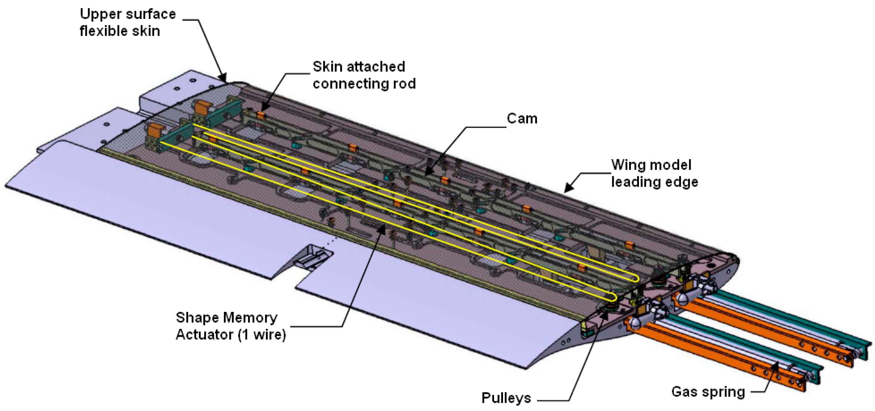
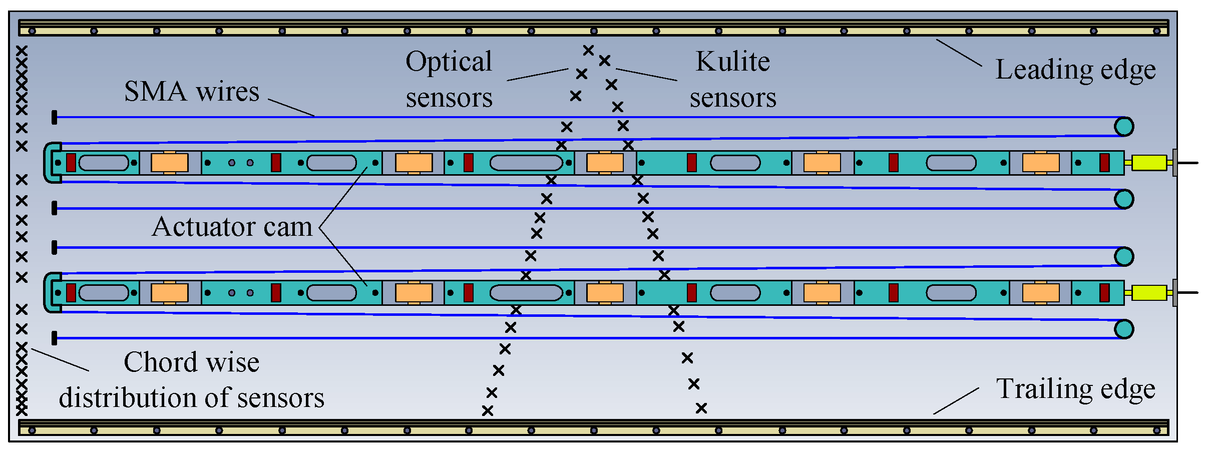
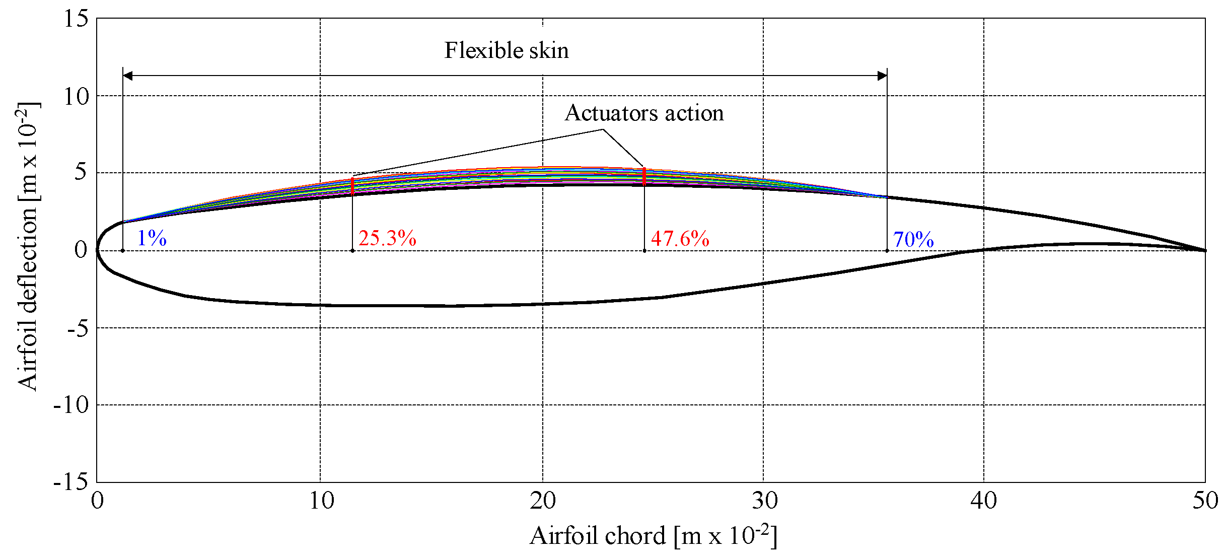
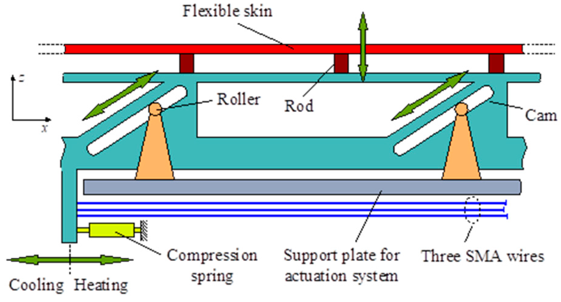
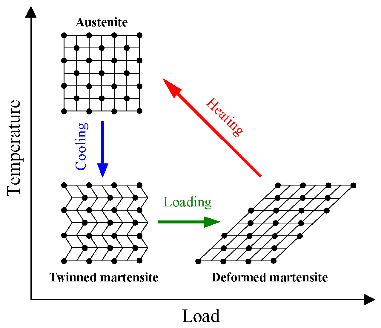
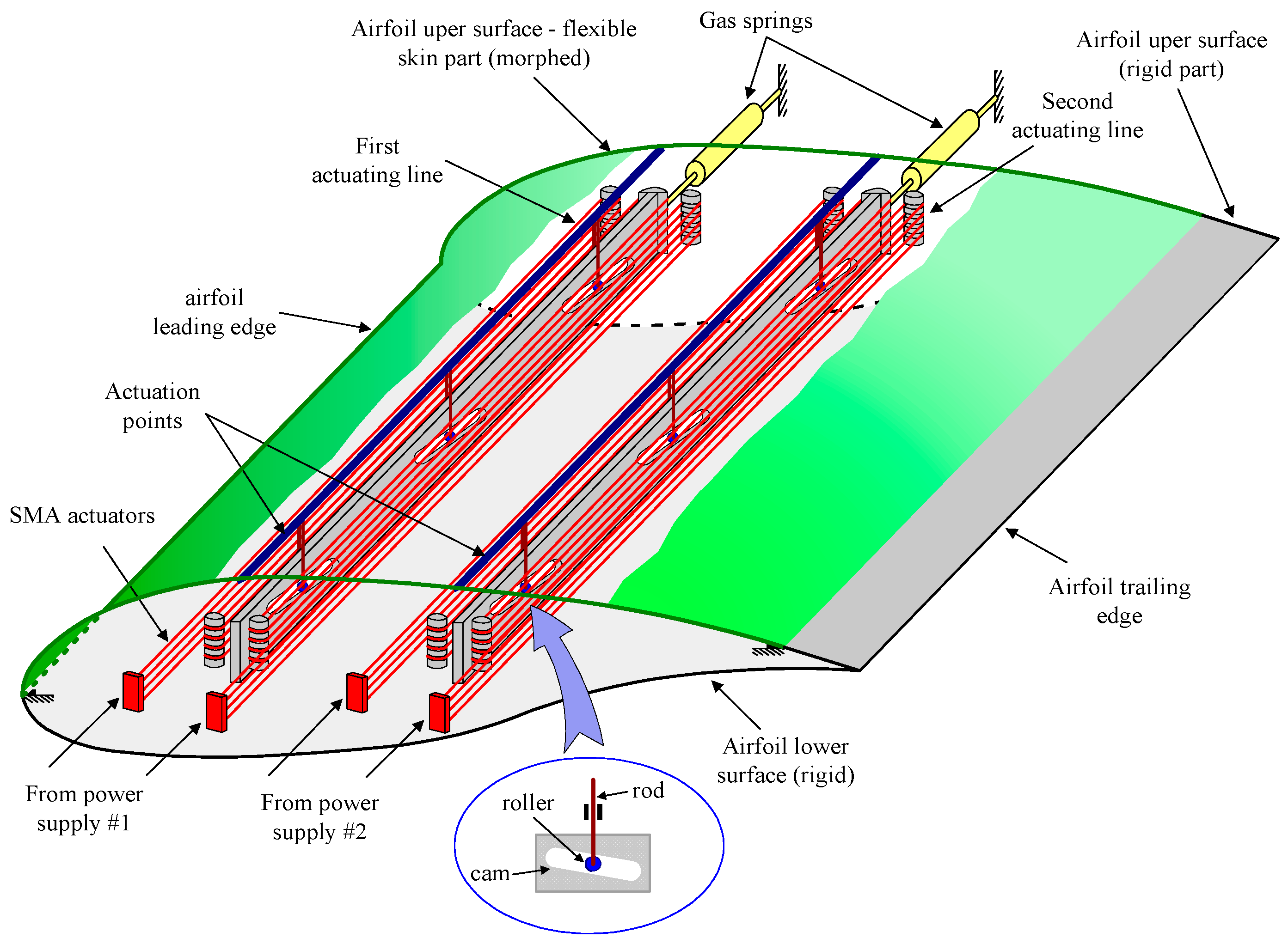
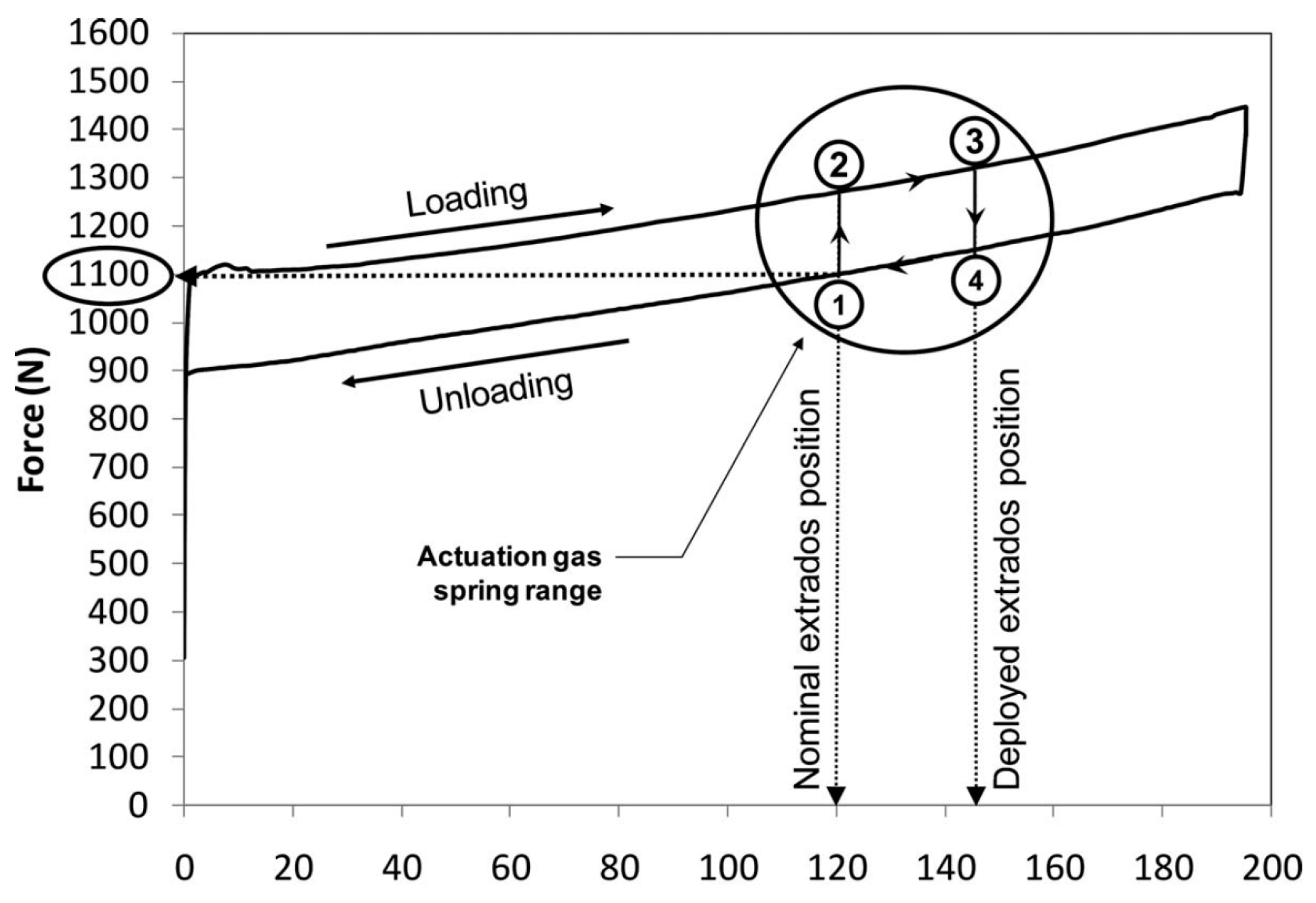
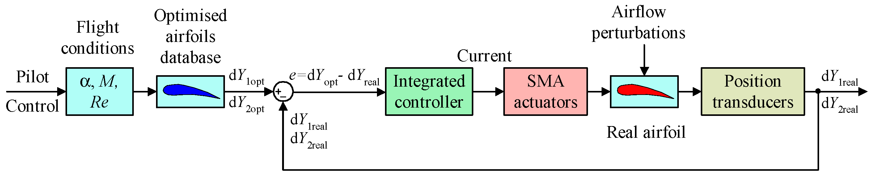
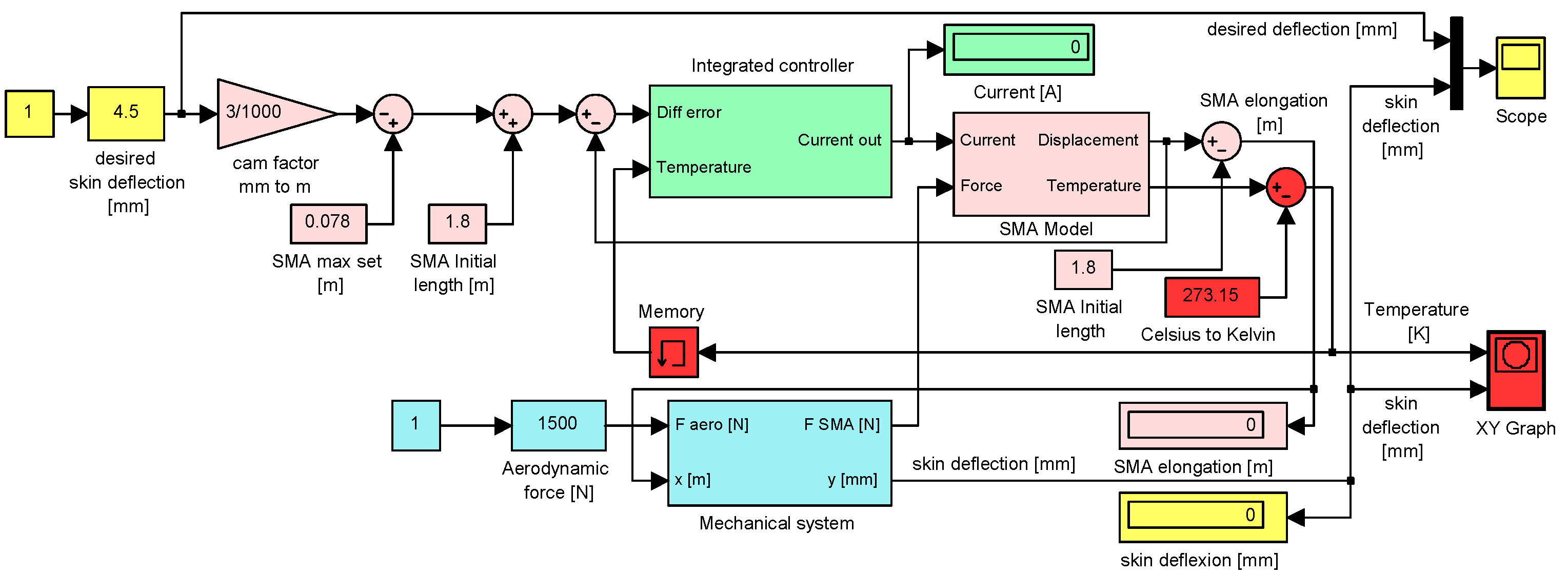
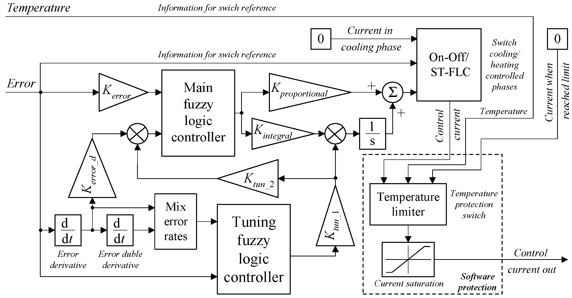
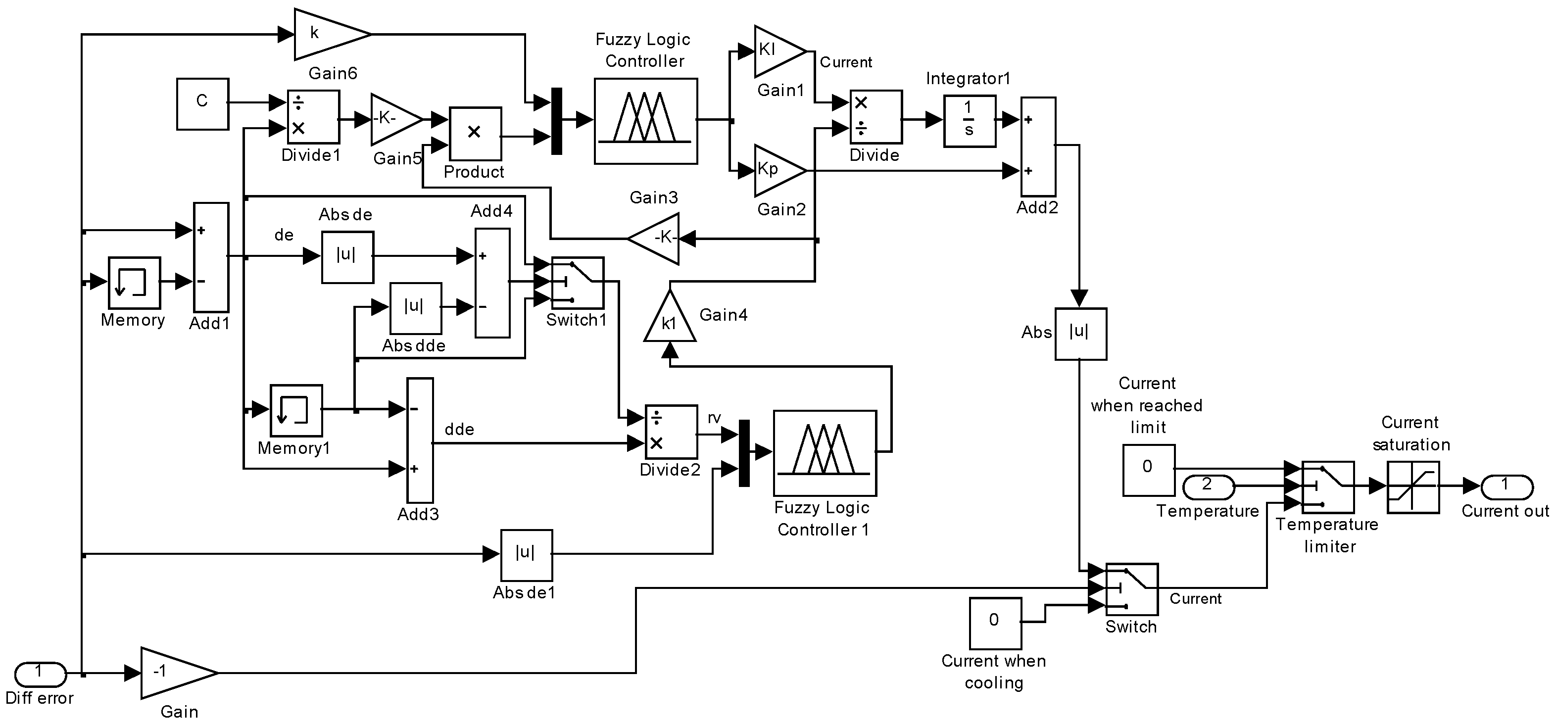
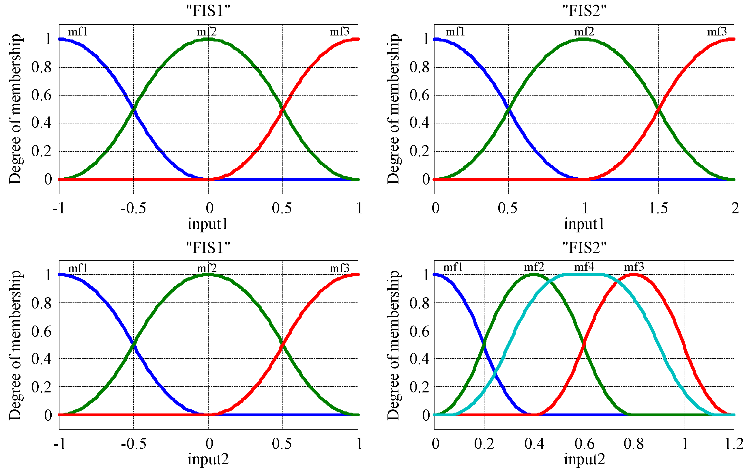
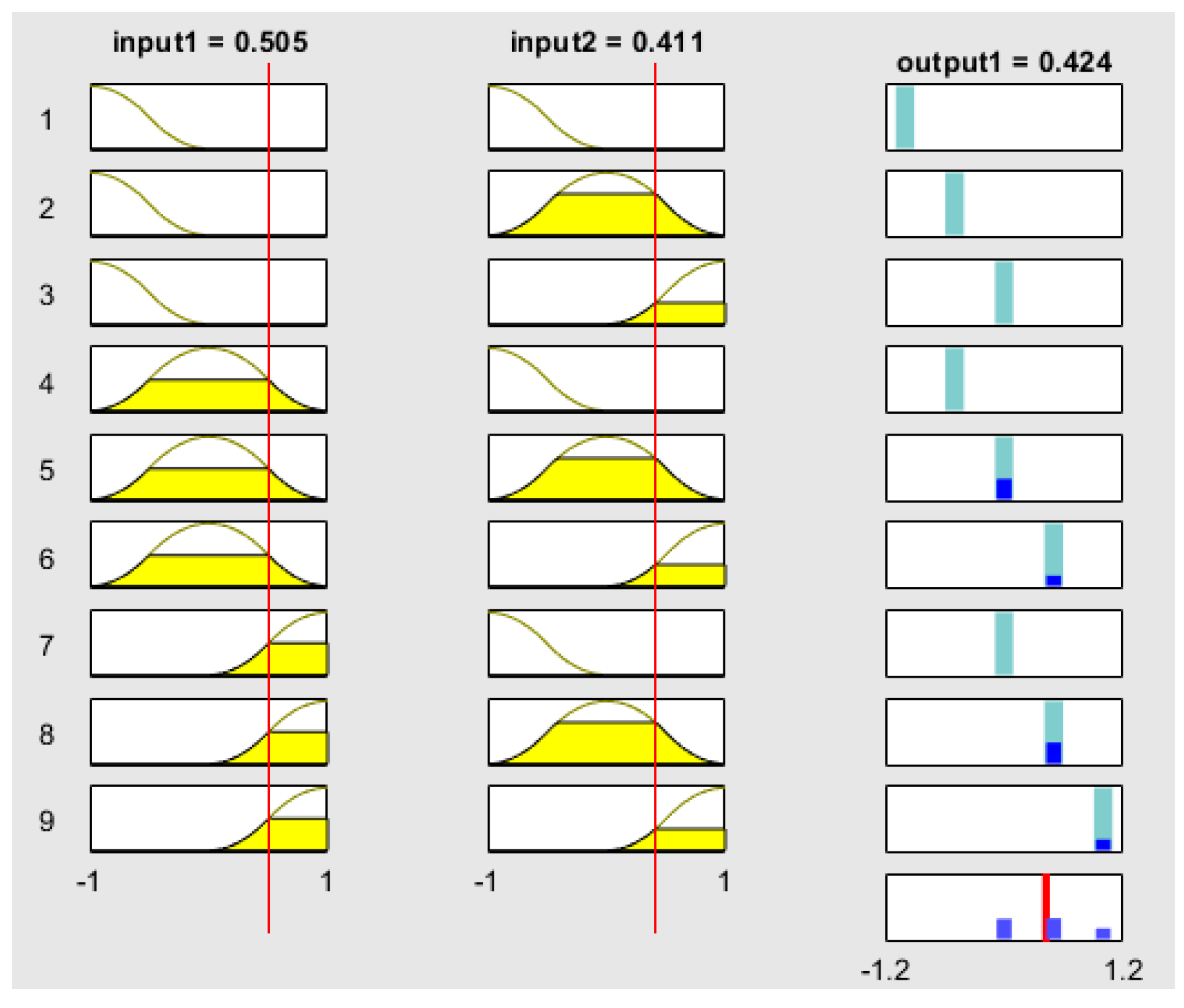
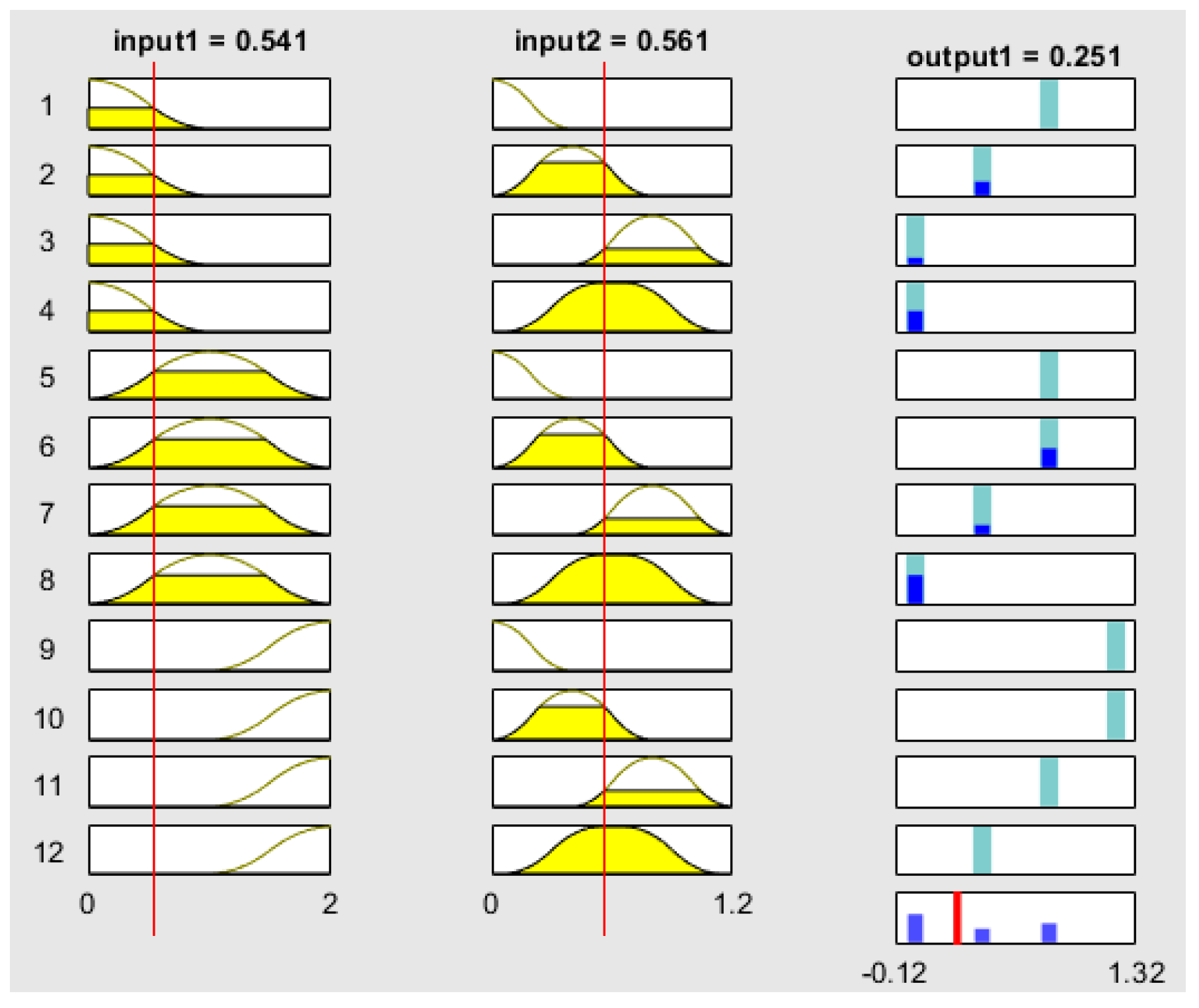
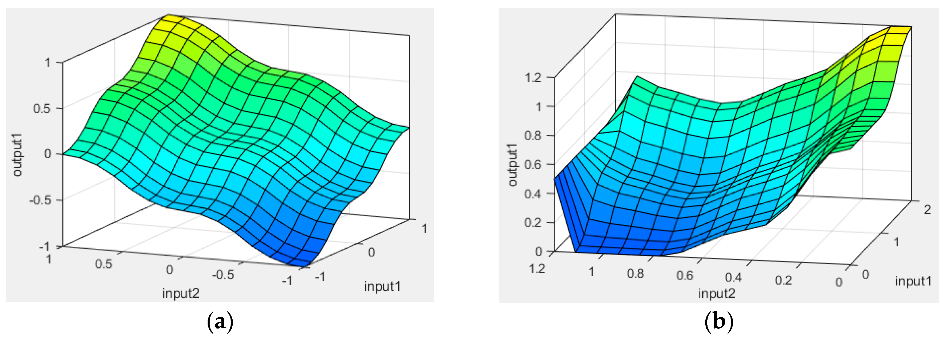
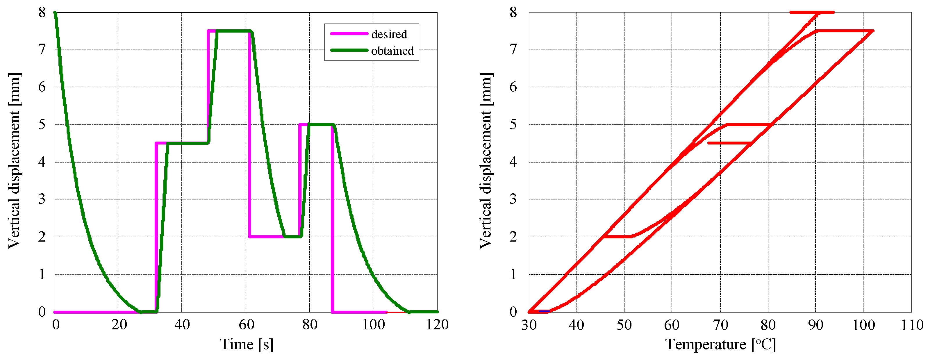
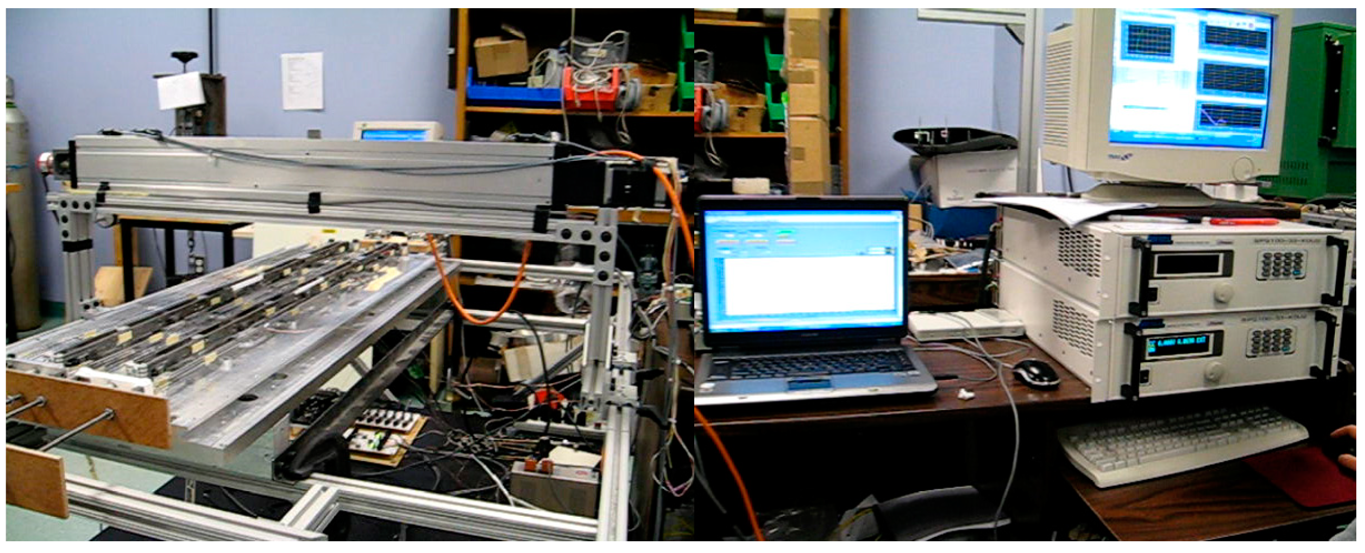
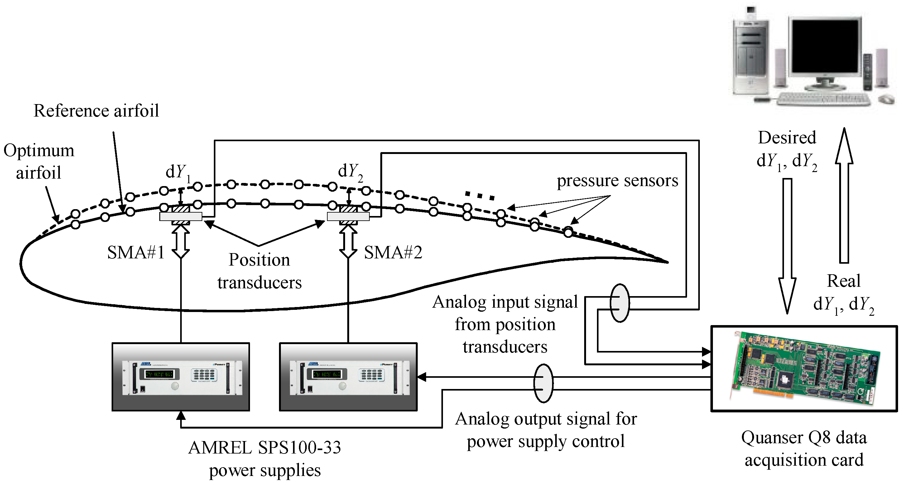
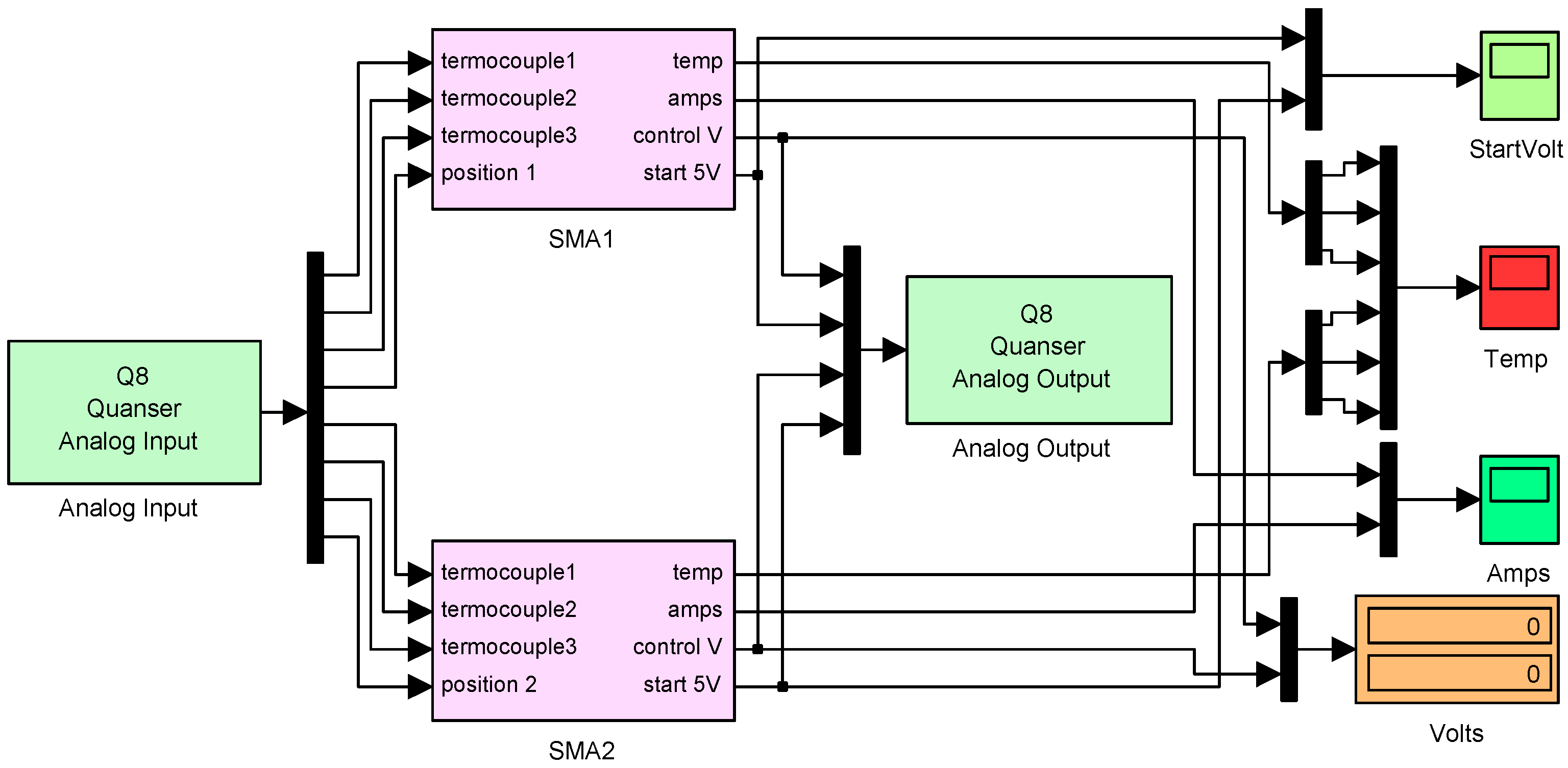
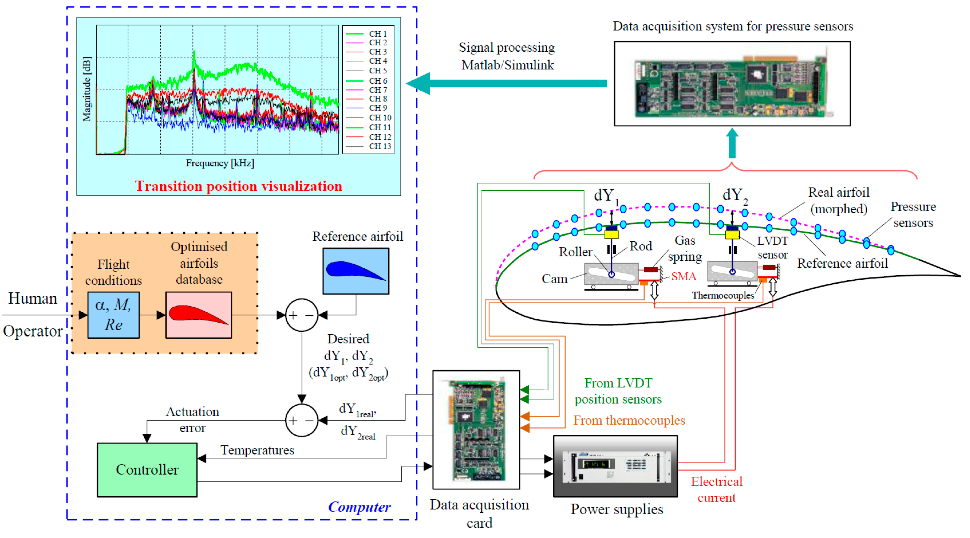
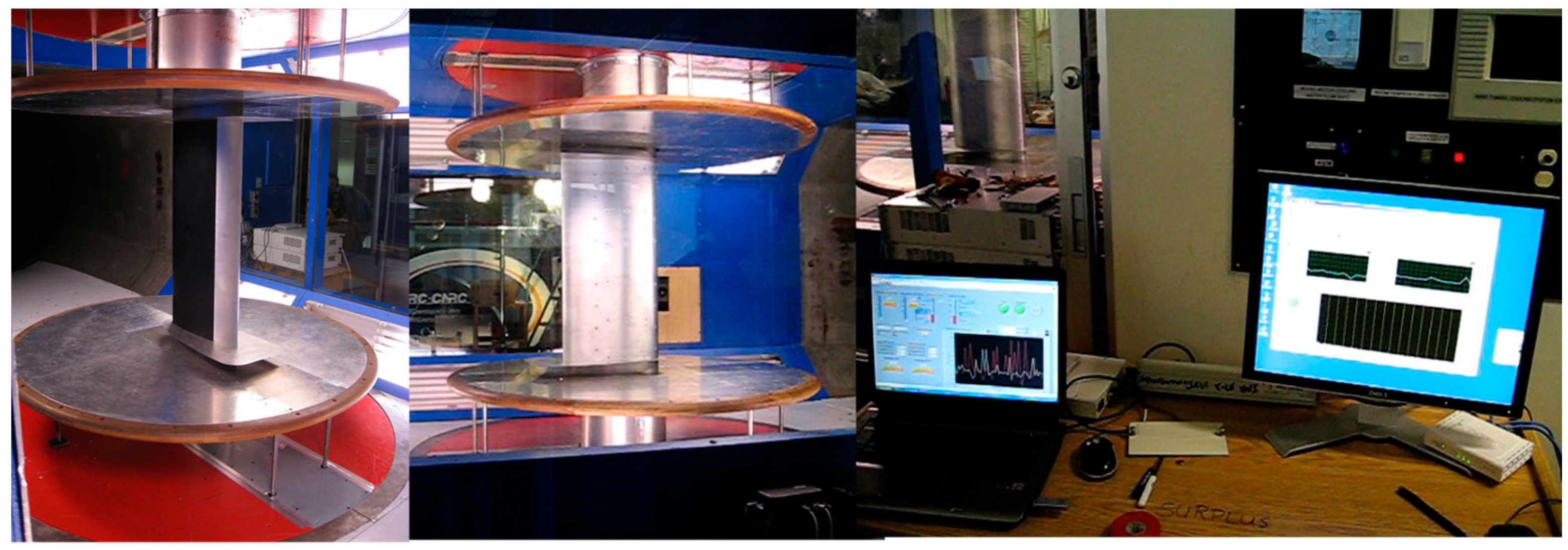
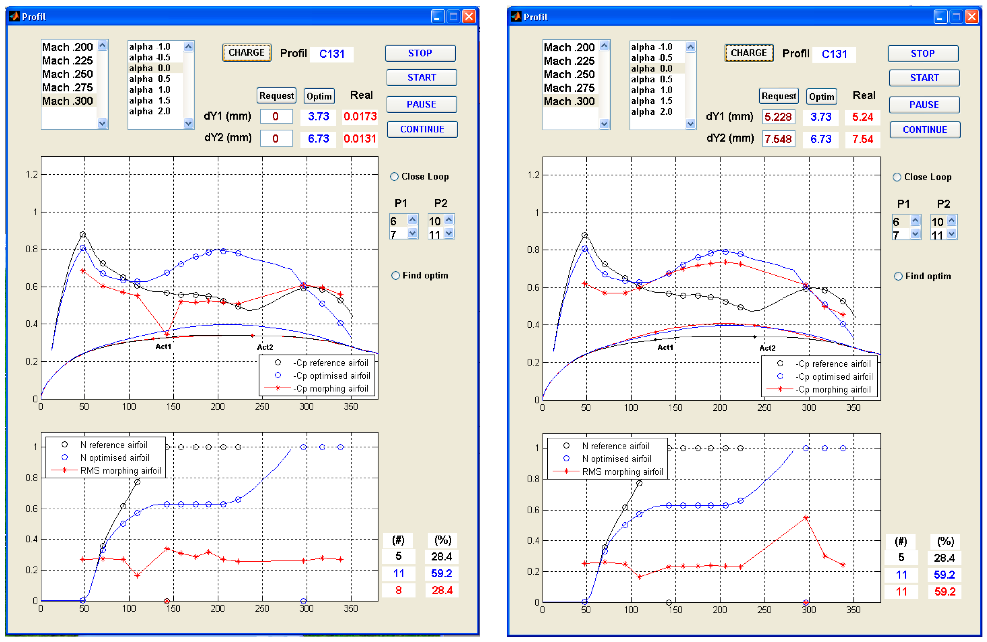
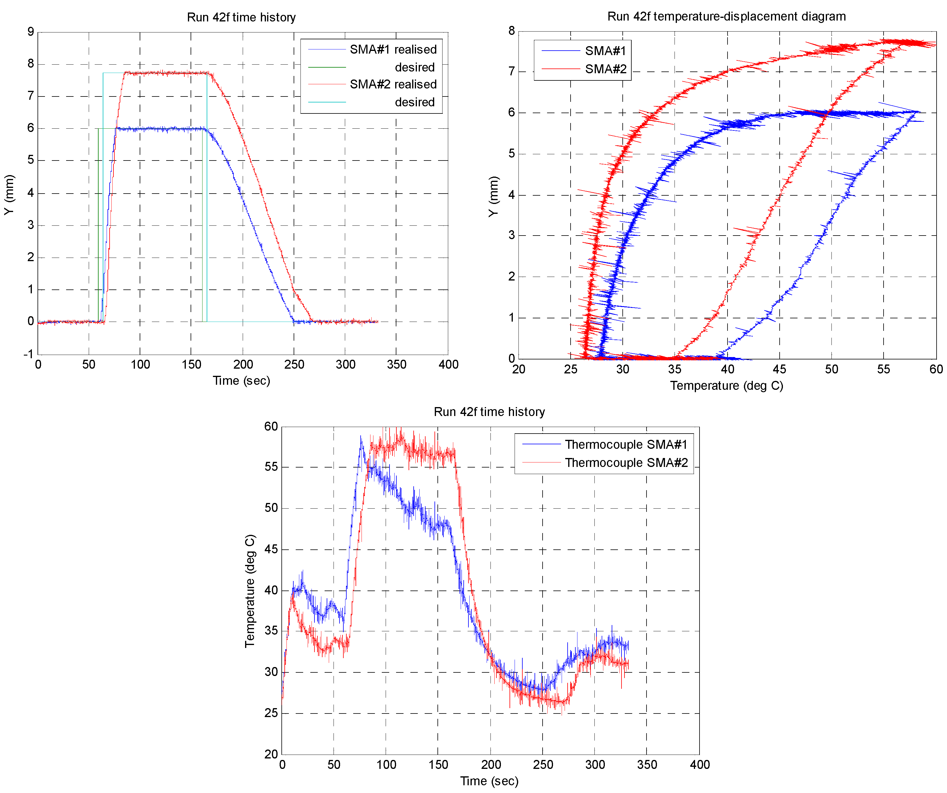
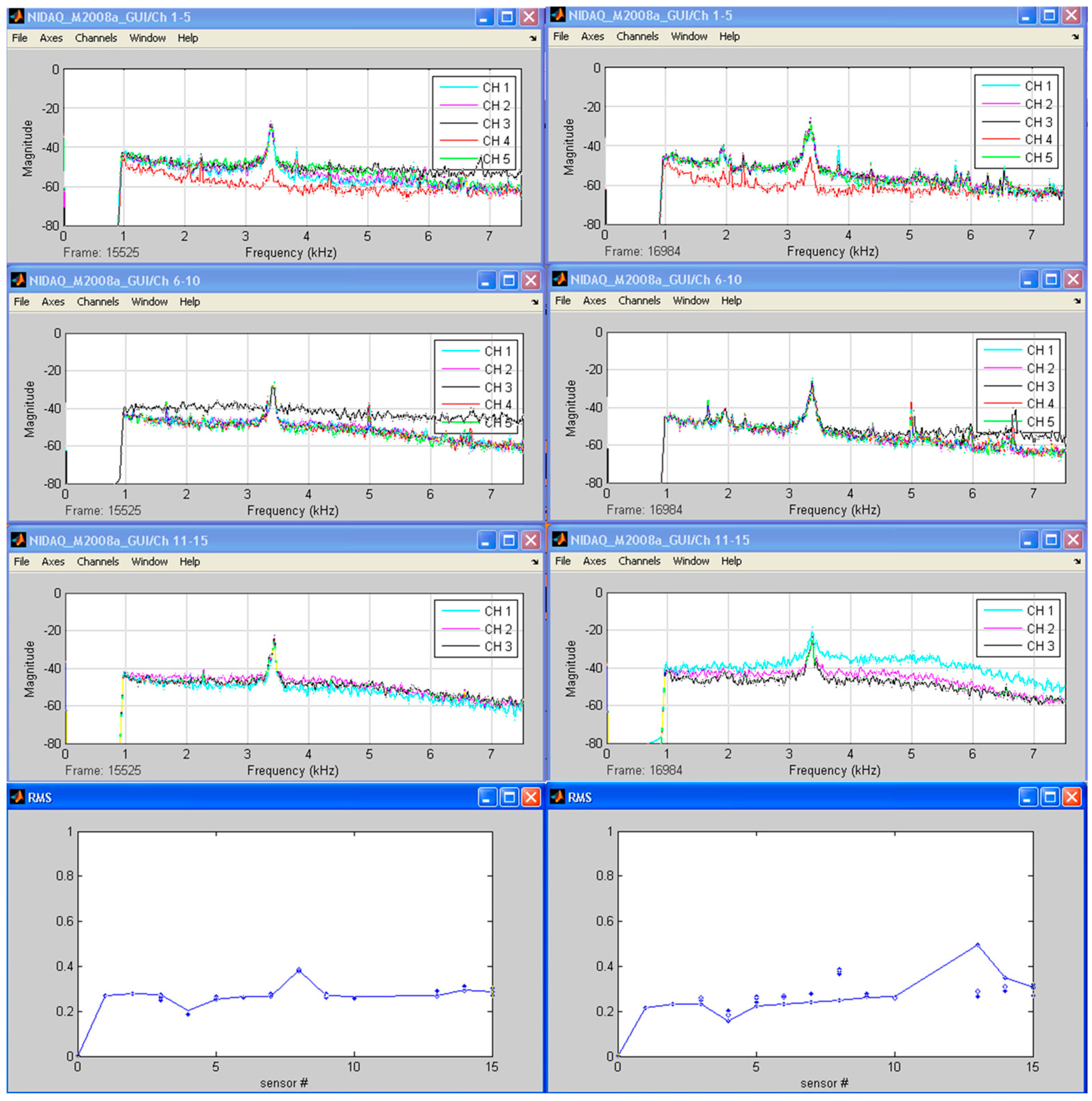
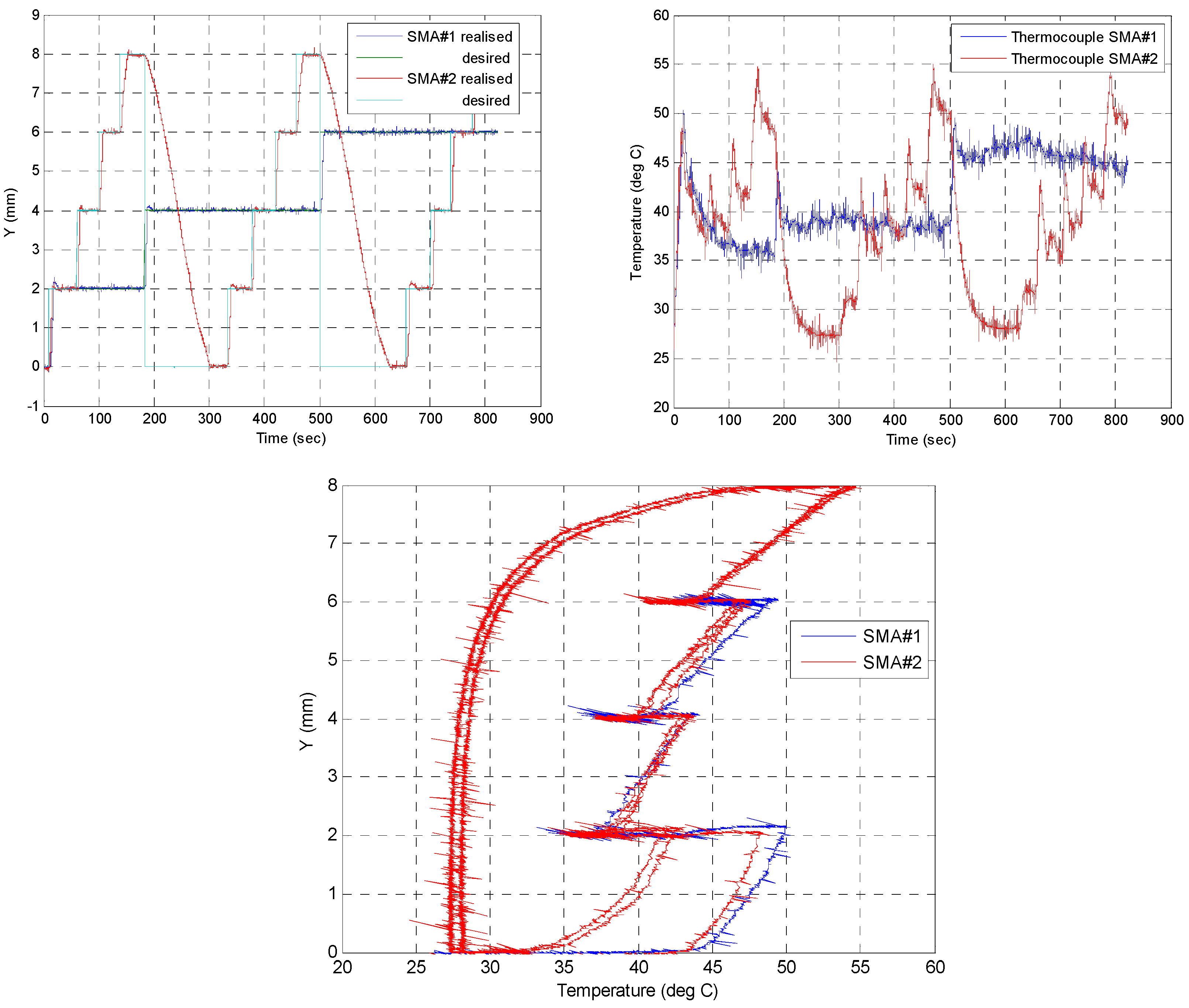
Table 1.
The parameters of the mfs associated to the inputs of the FIS1.
| Input | mf | mf Type | mf Parameters | |||
|---|---|---|---|---|---|---|
| 1 and 2 | mf1 ( | z–function | −1 | – | – | 0 |
| mf2 ( | π–function | −1 | 0 | 0 | 1 | |
| mf3 ( | s–function | 0 | – | – | 1 | |
Table 2.
The parameters of the mfs associated to the inputs of the FIS2.
| Input | mf | mf Type | mf Parameters | |||
|---|---|---|---|---|---|---|
| 1 | mf1 ( | z–function | 0 | – | – | 1 |
| mf2 ( | π–function | 0 | 1 | 1 | 2 | |
| mf3 ( | s–function | 1 | – | – | 2 | |
| 2 | mf1 ( | z–function | 0 | – | – | 0.4 |
| mf2 ( | π–function | 0 | 0.4 | 0.4 | 0.8 | |
| mf3 ( | π–function | 0.4 | 0.4 | 0.8 | 1.2 | |
| mf3 ( | π–function | 0.06 | 0.54 | 0.66 | 1.14 | |
Disclaimer/Publisher’s Note: The statements, opinions and data contained in all publications are solely those of the individual author(s) and contributor(s) and not of MDPI and/or the editor(s). MDPI and/or the editor(s) disclaim responsibility for any injury to people or property resulting from any ideas, methods, instructions or products referred to in the content. |
© 2023 by the authors. Licensee MDPI, Basel, Switzerland. This article is an open access article distributed under the terms and conditions of the Creative Commons Attribution (CC BY) license (https://creativecommons.org/licenses/by/4.0/).
Share and Cite
MDPI and ACS Style
Grigorie, T.L.; Botez, R.M. A Self–Tuning Intelligent Controller for a Smart Actuation Mechanism of a Morphing Wing Based on Shape Memory Alloys. Actuators 2023, 12, 350. https://doi.org/10.3390/act12090350
AMA Style
Grigorie TL, Botez RM. A Self–Tuning Intelligent Controller for a Smart Actuation Mechanism of a Morphing Wing Based on Shape Memory Alloys. Actuators. 2023; 12(9):350. https://doi.org/10.3390/act12090350
Chicago/Turabian StyleGrigorie, Teodor Lucian, and Ruxandra Mihaela Botez. 2023. "A Self–Tuning Intelligent Controller for a Smart Actuation Mechanism of a Morphing Wing Based on Shape Memory Alloys" Actuators 12, no. 9: 350. https://doi.org/10.3390/act12090350
Note that from the first issue of 2016, this journal uses article numbers instead of page numbers. See further details here.