
Evaluation of Fiber-Reinforced Modular Soft Actuators for Individualized Soft Rehabilitation Gloves

 , , , ,
Abstract
:1. Introduction
2. Individual Differences of Fingers and Requirements for Individualized SRGs
2.1. Hand Finger’s Size
2.2. Joint ROM and Stiffness
2.3. Requirements of SRGs Actuators for Individual Adaptation
- A mechanical design that can adapt to differences in finger dimensions;
- Sufficient assist force for coping with joint stiffness;
- Customizability to different individual joint levels;
- Low cost of fabrication, customization, and assembly for individualization.
3. Actuator Design
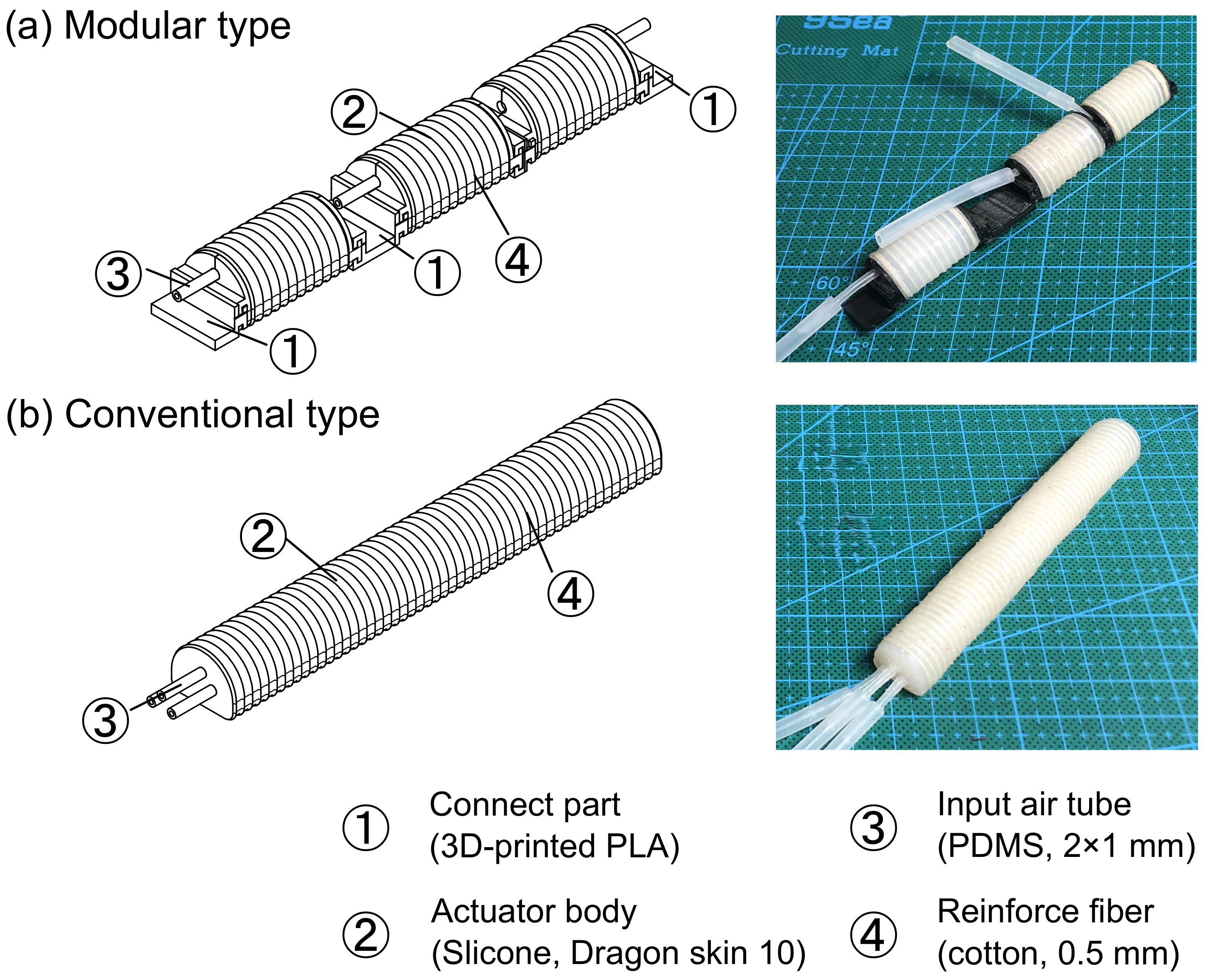
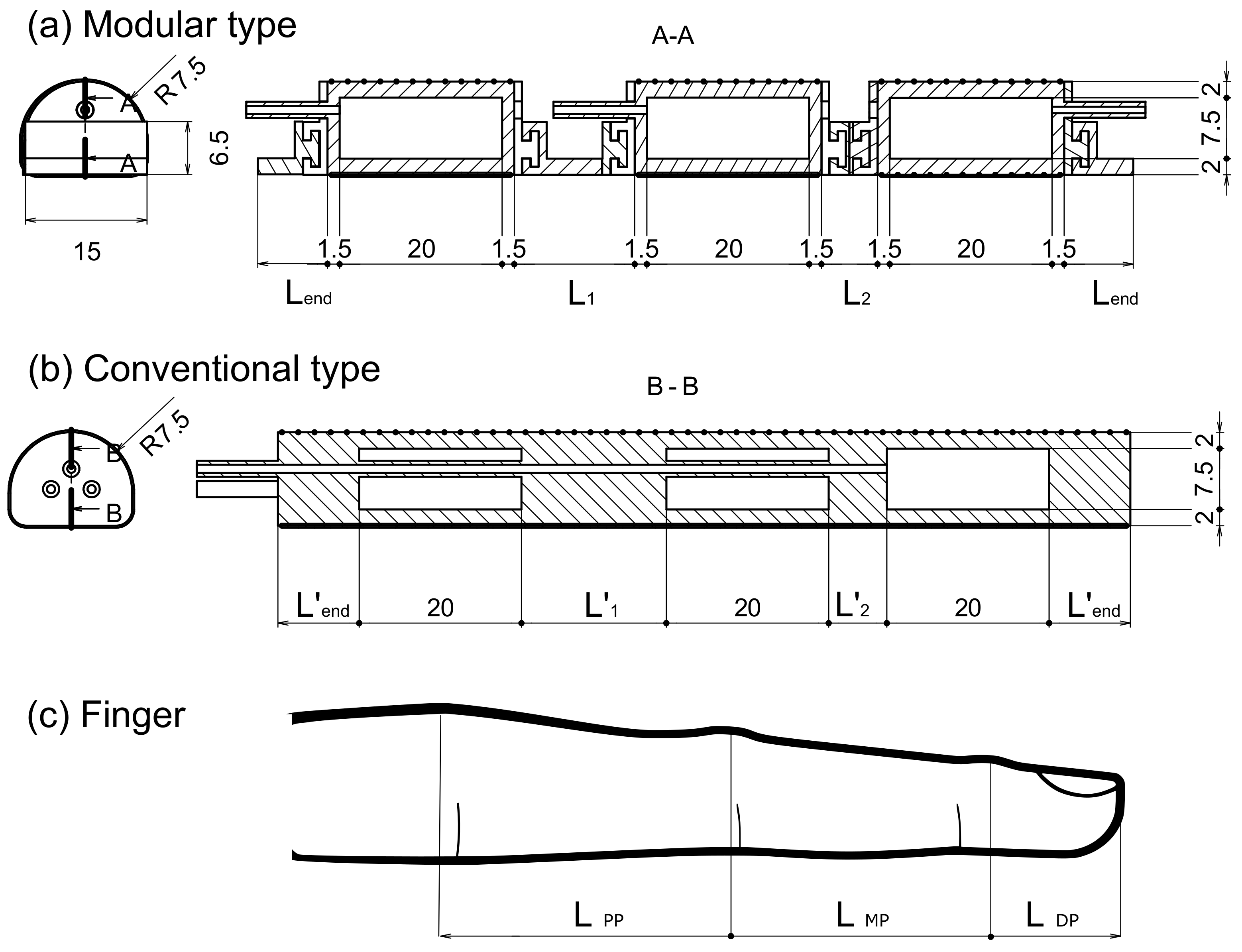
3.1. Modular Type
3.2. Conventional Type
4. Fabrication
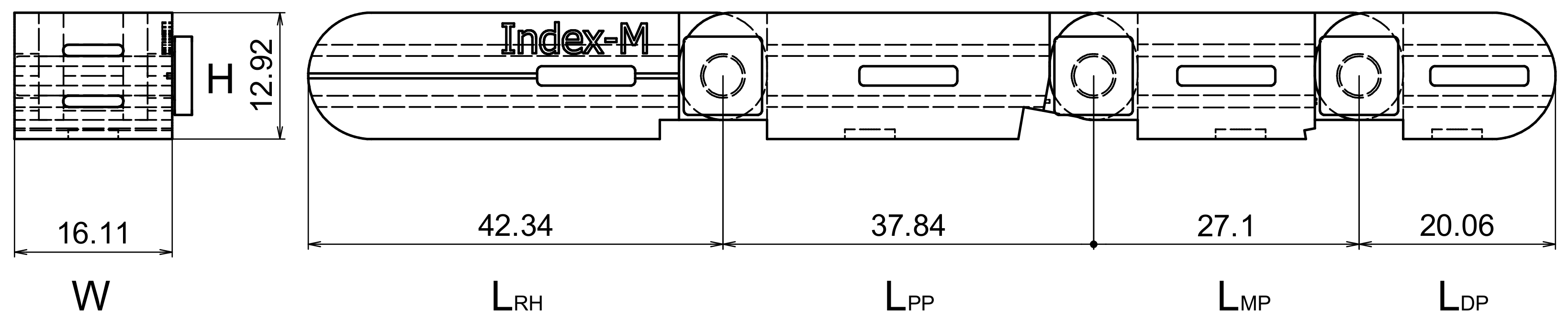
4.1. Parameters of the Individual Differences
4.2. Actuators
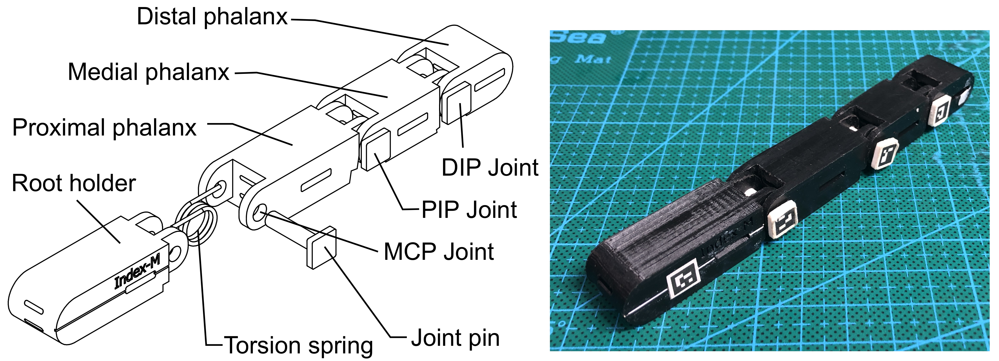
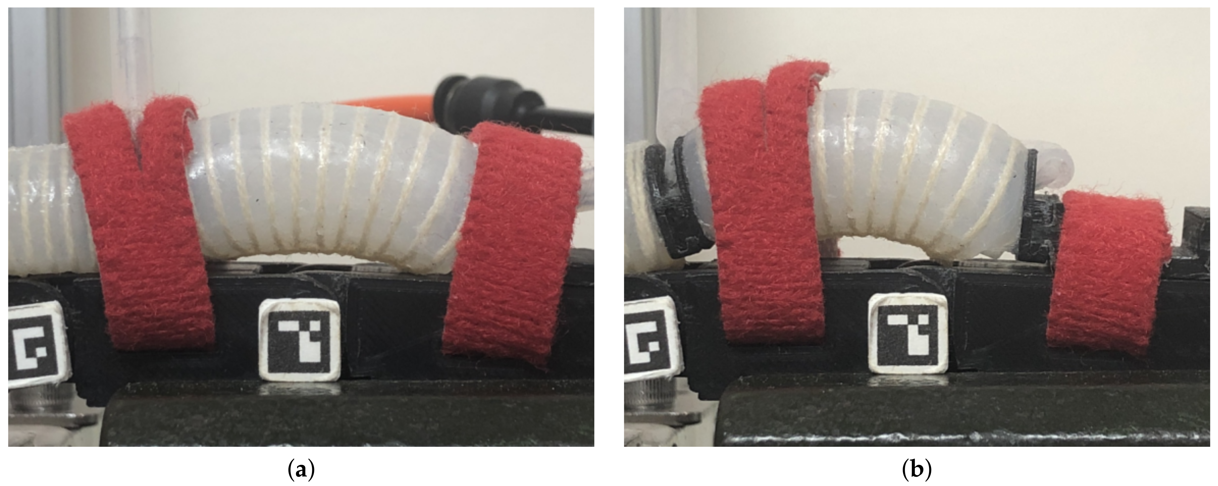
4.3. Dummy Finger
5. Evaluation
5.1. Characterizations of the Fabricated Actuators
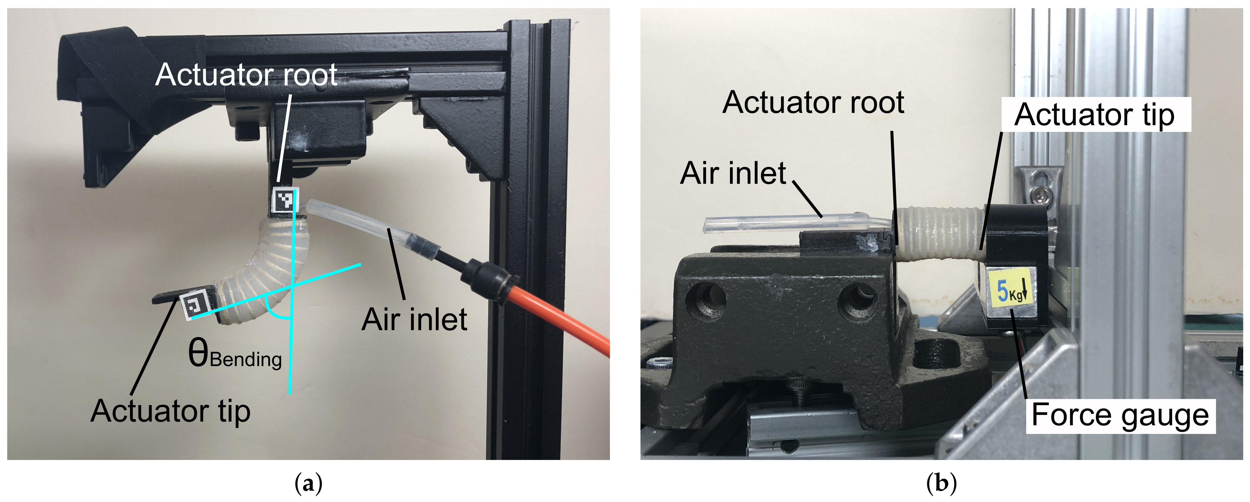
5.1.1. Bending Angle
5.1.2. Tip Force
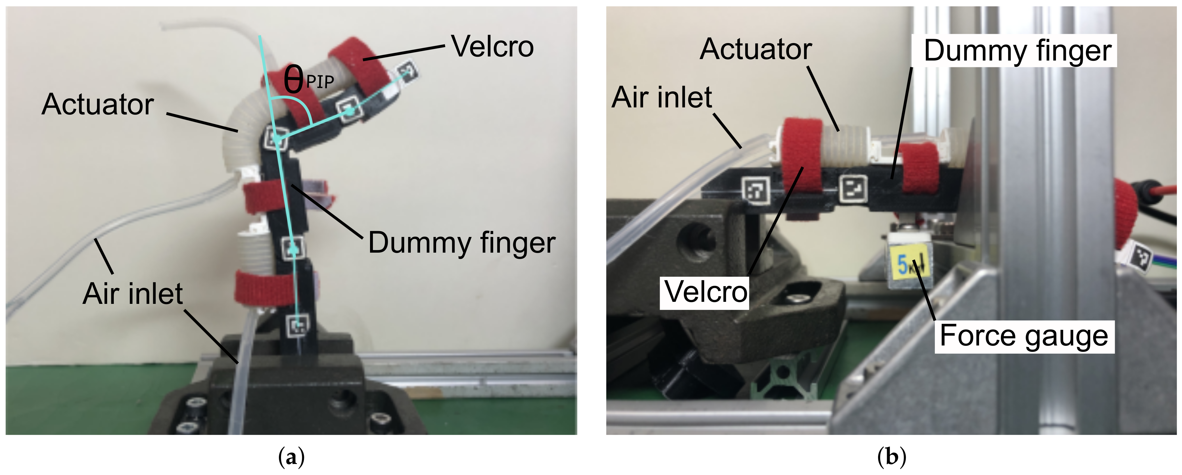
5.2. The Evaluation Experiments
6. Results
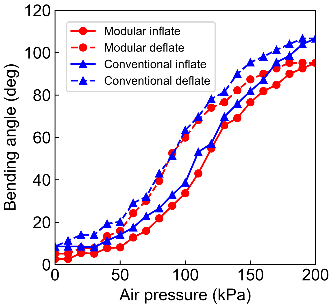
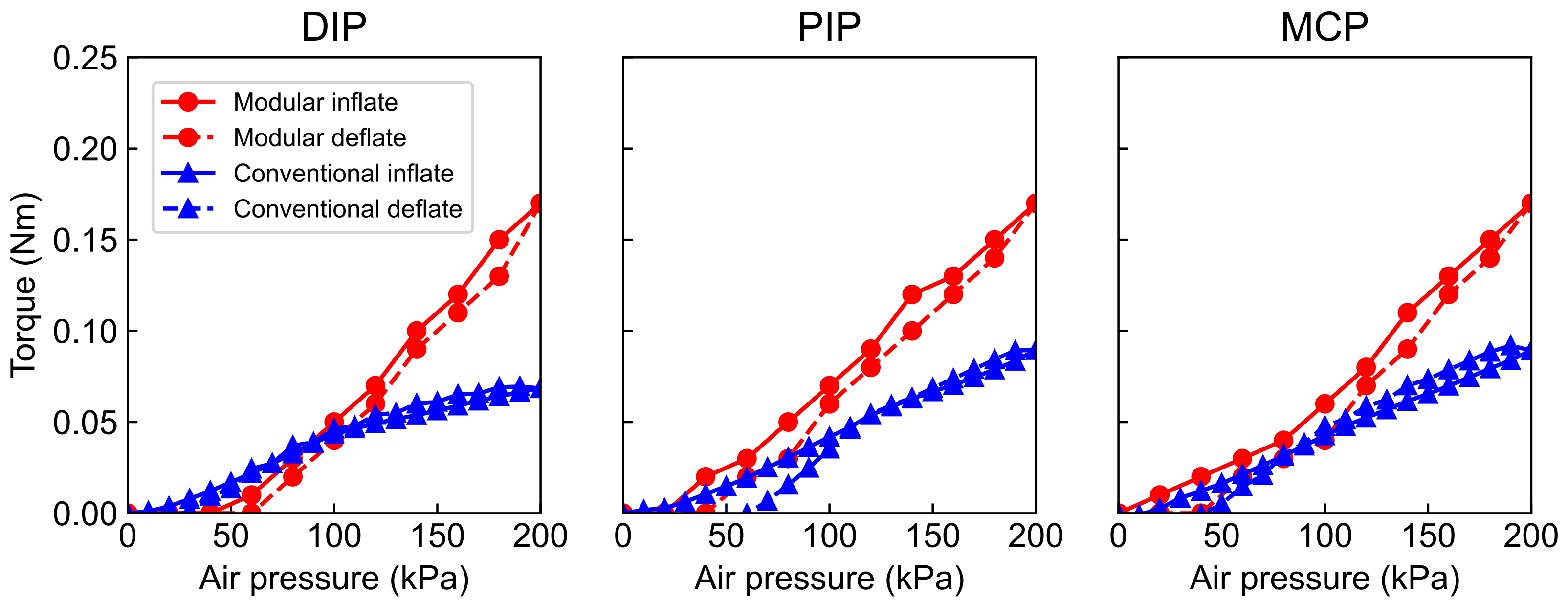
6.1. Bending Performance of the Modular and Conventional Soft Actuators
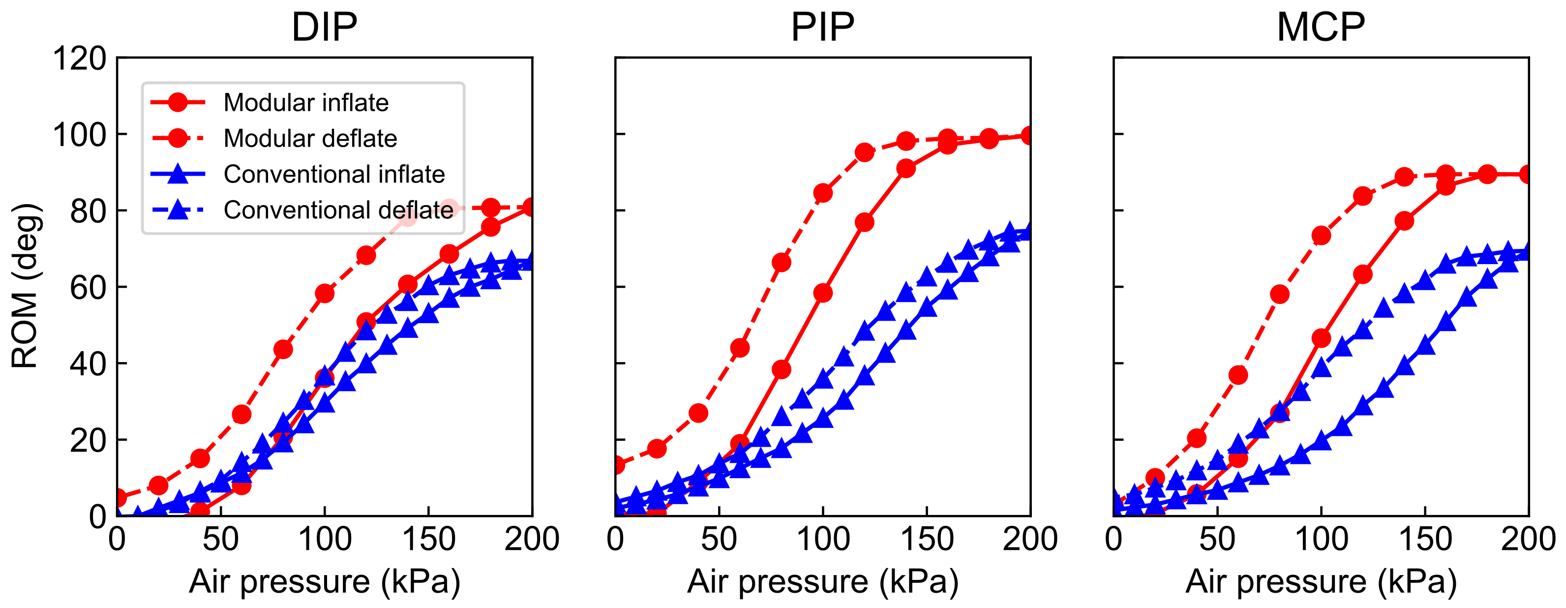
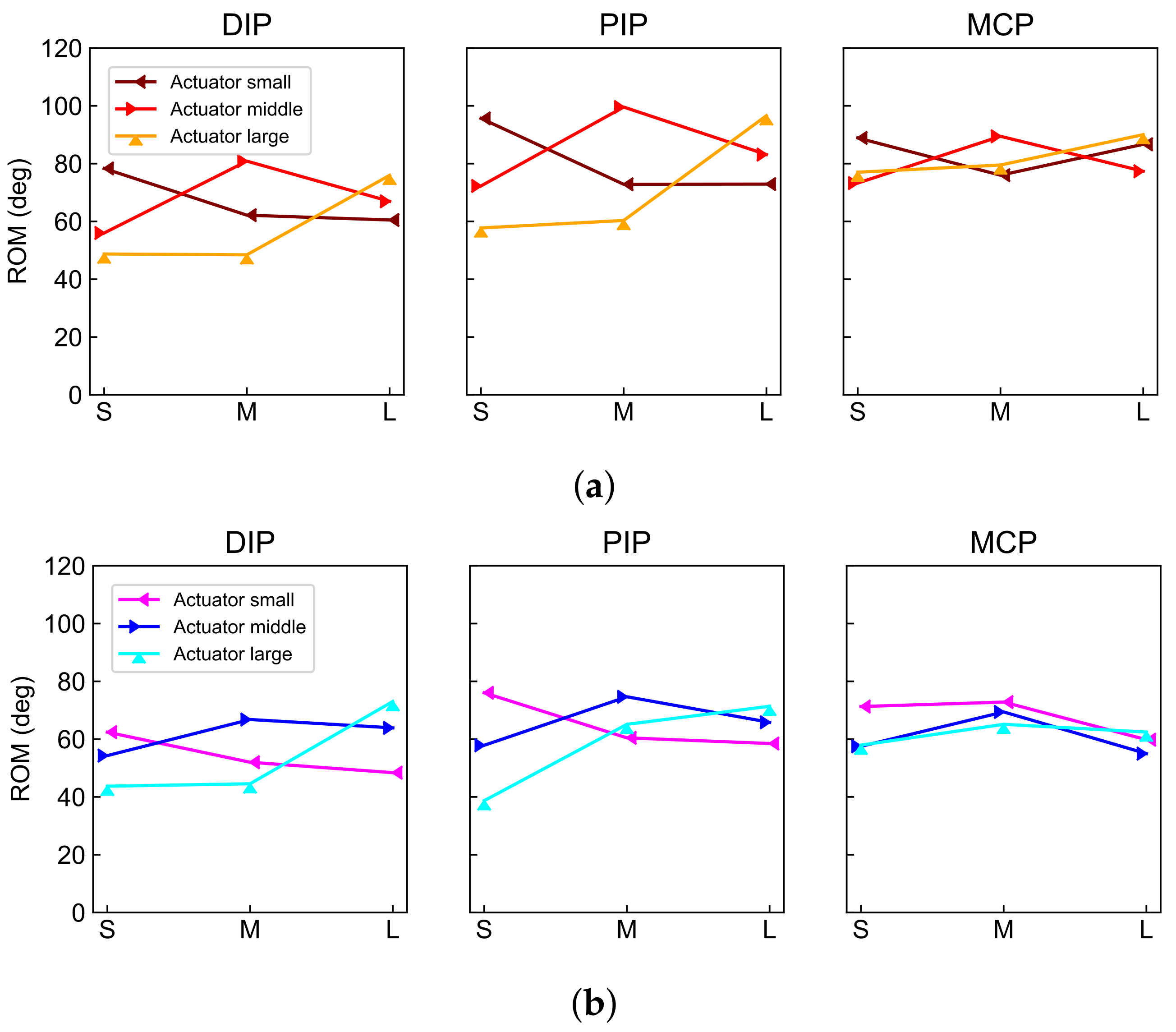
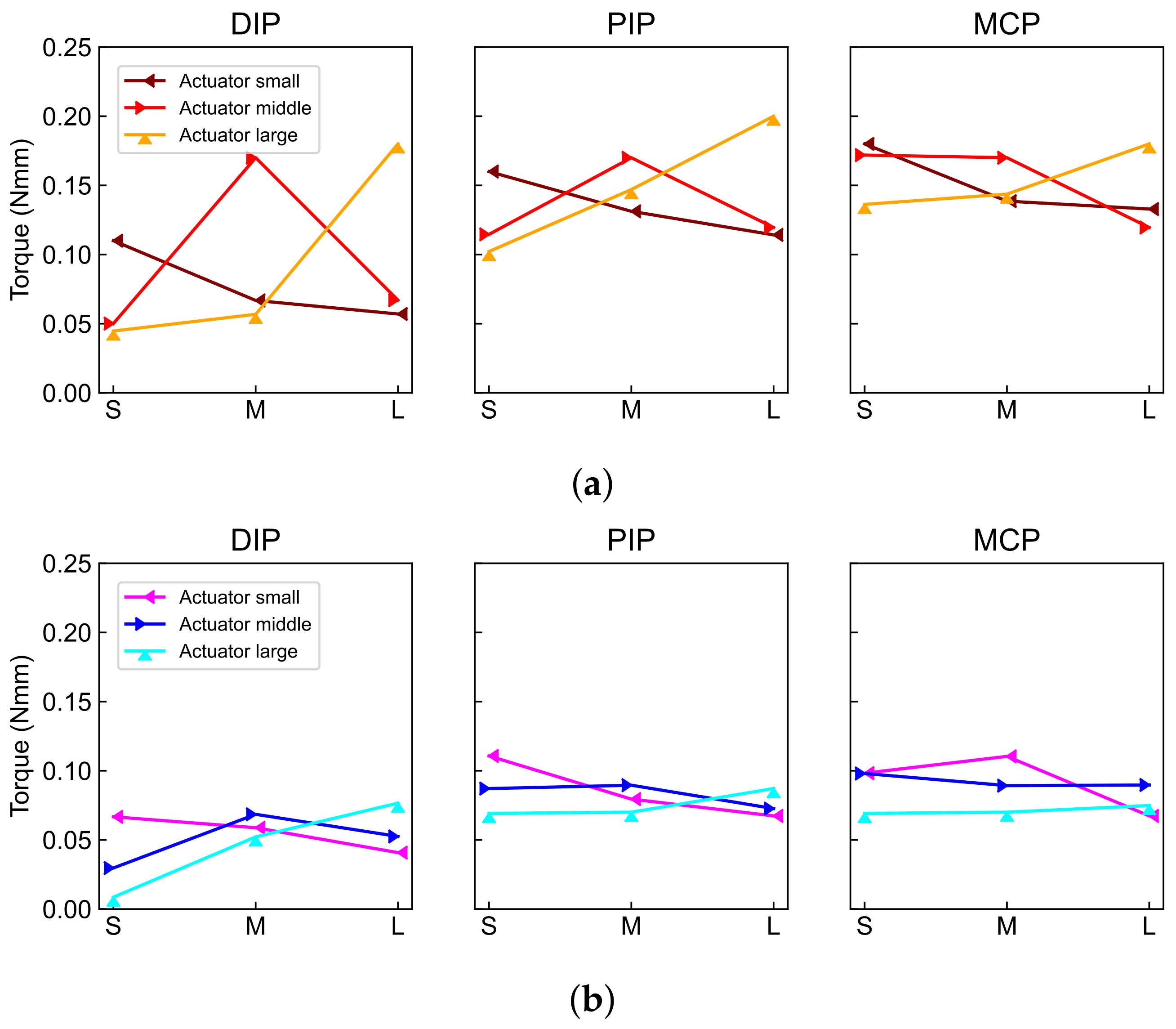
6.2. Bending Performance of Different Actuators Banded with Dummy Fingers of Different Sizes
7. Discussion
7.1. Comparison of the Bending Performance of Two Types of Soft Actuators
7.2. Importance of Size Matching between Actuators and Dummy Fingers
8. Conclusions
Author Contributions
Funding
Institutional Review Board Statement
Acknowledgments
Conflicts of Interest
Abbreviations
| SRG | Soft rehabilitation glove |
| ROM | Range of motion |
| DP | Distal phalanx |
| PP | Proximal phalanx |
| MP | Medial phalanx |
| DIP | Distal interphalangeal (joint) |
| PIP | Proximal interphalangeal (joint) |
| MCP | Metacarpophalangeal (joint) |
| FBD | Free body diagram |
References
- World Stroke Organization. Global Stroke Fact Sheet 2016. 2016. Available online: https://www.world-stroke.org (accessed on 17 June 2019).
- Kwakkel, G.; Kollen, B.J.; Van der Grond, J.V.; Prevo, A.J. Probability of regaining dexterity in the flaccid upper limb: Impact of severity of paresis and time since onset in acute stroke. Stroke 2003, 34, 2181–2186. [Google Scholar] [CrossRef] [Green Version]
- Choi, Y.I.; Song, C.S.; Chun, B.Y. Activities of daily living and manual hand dexterity in persons with idiopathic Parkinson disease. J. Phys. Ther. Sci. 2017, 29, 457–460. [Google Scholar] [CrossRef] [PubMed] [Green Version]
- Wang, D.; Meng, Q.; Meng, Q.; Li, X.; Yu, H. Design and Development of a Portable Exoskeleton for Hand Rehabilitation. IEEE Trans. Neural Syst. Rehabil. Eng. 2018, 26, 2376–2386. [Google Scholar] [CrossRef]
- Abdallah, I.; Bouteraa, Y.; Rekik, C. Design and Development of 3D Printed Myoelectric Robotic Exoskeleton for Hand Rehabilitation. J. Smart Sens. Intell. Syst. 2006, 10, 341–366. [Google Scholar] [CrossRef] [Green Version]
- Chiri, A.; Vitiello, N.; Giovacchini, F.; Roccella, S.; Vecchi, F.; Carrozza, M.C. Mechatronic design and characterization of the index finger module of a hand exoskeleton for post-stroke rehabilitation. IEEE/ASME Trans. Mechatron. 2012, 17, 884–894. [Google Scholar] [CrossRef]
- Polygerinos, P.; Wang, Z.; Galloway, K.C.; Wood, R.J.; Walsh, C.J. Soft robotic glove for combined assistance and at-home rehabilitation. Robot. Auton. Syst. 2015, 73, 135–143. [Google Scholar] [CrossRef] [Green Version]
- Yap, H.K.; Khin, P.M.; Koh, T.H.; Sun, Y.; Liang, X.; Lim, J.H.; Yeow, C.H. A Fully Fabric-Based Bidirectional Soft Robotic Glove for Assistance and Rehabilitation of Hand Impaired Patients. IEEE Robot. Autom. Lett. 2017, 2, 1383–1390. [Google Scholar] [CrossRef]
- Al-Fahaam, H.; Davis, S.; Nefti-Meziani, S. The design and mathematical modelling of novel extensor bending pneumatic artificial muscles (EBPAMs) for soft exoskeletons. Robot. Auton. Syst. 2018, 99, 63–74. [Google Scholar] [CrossRef]
- Tarvainen, T.; Yu, W. Pneumatic Multi-Pocket Elastomer Actuators for Metacarpophalangeal Joint Flexion and Abduction-Adduction. Actuators 2017, 6, 27. [Google Scholar] [CrossRef] [Green Version]
- Stilli, A.; Cremoni, A.; Bianchi, M.; Ridolfi, A.; Gerii, F.; Vannetti, F.; Wurdemann, H.A.; Allotta, B.; Althoefer, K. AirExGlove-A novel pneumatic exoskeleton glove for adaptive hand rehabilitation in post-stroke patients. In Proceedings of the 2018 IEEE International Conference on Soft Robotics, RoboSoft, Livorno, Italy, 24–28 April 2018; pp. 579–584. [Google Scholar] [CrossRef] [Green Version]
- Yap, H.K.; Lim, J.H.; Goh, J.C.H.; Yeow, C.H. Design of a soft robotic glove for hand rehabilitation of stroke patients with clenched fist deformity using inflatable plastic actuators. J. Med. Devices Trans. ASME 2016, 10, 5–10. [Google Scholar] [CrossRef]
- Yap, H.K.; Lim, J.H.; Nasrallah, F.; Yeow, C.H. Design and preliminary feasibility study of a soft robotic glove for hand function assistance in stroke survivors. Front. Neurosci. 2017, 11, 547. [Google Scholar] [CrossRef] [PubMed] [Green Version]
- Polygerinos, P.; Galloway, K.C.; Savage, E.; Herman, M.; O’Donnell, K.; Walsh, C.J. Soft robotic glove for hand rehabilitation and task specific training. In Proceedings of the IEEE International Conference on Robotics and Automation, Seattle, WA, USA, 25–30 May 2015; pp. 2913–2919. [Google Scholar] [CrossRef]
- Shiota, K.; Kokubu, S.; Tarvainen, T.V.; Sekine, M.; Kita, K.; Huang, S.Y.; Yu, W. Enhanced Kapandji test evaluation of a soft robotic thumb rehabilitation device by developing a fiber-reinforced elastomer-actuator based 5-digit assist system. Robot. Auton. Syst. 2019, 111, 20–30. [Google Scholar] [CrossRef]
- Yun, S.S.; Kang, B.B.; Cho, K.J. Exo-Glove PM: An Easily Customizable Modularized Pneumatic Assistive Glove. IEEE Robot. Autom. Lett. 2017, 2, 1725–1732. [Google Scholar] [CrossRef]
- Mallon, W.J.; Brown, H.R.; Nunley, J.A. Digital ranges of motion: Normal values in young adults. J. Hand Surg. 1991, 16, 882–887. [Google Scholar] [CrossRef]
- Shaw, S.J.; Morris, M.A. The range of motion of the metacarpophalangeal joint of the thumb and its relationship to injury. J. Hand Surg. Br. Eur. Vol. 1992, 17, 164–166. [Google Scholar] [CrossRef]
- Elaine, E.F.; Cynthia, A.P.; James, W.S. Hand Splinting: Principles and Methods, Japanese Translation; The C. V. Mosby Company: Maryland Heights, MO, USA, 1981; pp. 80–97, 114–132. [Google Scholar]
- Mehrholz, J.; Pohl, M.; Platz, T.; Kugler, J.; Elsner, B. Electromechanical and robot-assisted arm training for improving activities of daily living, arm function, and arm muscle strength after stroke. Cochrane Database Syst. Rev. 2018, 2018, 9. [Google Scholar] [CrossRef]
- Bos, R.A.; Haarman, C.J.; Stortelder, T.; Nizamis, K.; Herder, J.L.; Stienen, A.H.; Plettenburg, D.H. A structured overview of trends and technologies used in dynamic hand orthoses. J. NeuroEngineering Rehabil. 2016, 13, 62. [Google Scholar] [CrossRef] [Green Version]
- Fontana, L.; Neel, S.; Claise, J.M.; Ughetto, S.; Catilina, P. Osteoarthritis of the Thumb Carpometacarpal Joint in Women and Occupational Risk Factors: A Case–Control Study. J. Hand Surg. 2007, 32, 459–465. [Google Scholar] [CrossRef]
- Prange, G.B.; Smulders, L.C.; Van Wijngaarden, J.; Lijbers, G.J.; Nijenhuis, S.M.; Veltink, P.H.; Buurke, J.H.; Stienen, A.H. User requirements for assistance of the supporting hand in bimanual daily activities via a robotic glove for severely affected stroke patients. In Proceedings of the IEEE International Conference on Rehabilitation Robotics, Singapore, 11–14 August 2015; pp. 357–361. [Google Scholar] [CrossRef]
- Research Institute of Human Engineering for Quality Life. Human Hand Dimensions Data for Ergonomic Design 2010; Research Institute of Human Engineering for Quality Life: Osaka, Japan, 2010; pp. 38–40. [Google Scholar]
- Yang, G.; Mcglinn, E.P.; Chung, K.C. Management of the Stiff Finger: Evidence and Outcomes. Clin. Plast. Surg. 2014, 41, 501–512. [Google Scholar] [CrossRef] [Green Version]
- Kamper, D.G.; Rymer, W.Z. Quantitative features of the stretch response of extrinsic finger muscles in hemiparetic stroke. Muscle Nerve 2000, 23, 954–961. [Google Scholar] [CrossRef]
- Ueki, S.; Kawasaki, H.; Ito, S.; Nishimoto, Y.; Abe, M.; Aoki, T.; Ishigure, Y.; Ojika, T.; Mouri, T. Development of a hand-assist robot with multi-degrees-of-freedom for rehabilitation therapy. IEEE/ASME Trans. Mechatron. 2012, 17, 136–146. [Google Scholar] [CrossRef]
- Hu, D.; Zhang, J.; Yang, Y.; Li, Q.; Li, D.; Hong, J. A novel soft robotic glove with positive-negative pneumatic actuator for hand rehabilitation. In Proceedings of the IEEE/ASME International Conference on Advanced Intelligent Mechatronics (AIM), Boston, MA, USA, 6–10 July 2020; pp. 1840–1847. [Google Scholar] [CrossRef]
- Kokubu, S.; Yu, W. Developing a hybrid soft mechanism for assisting individualized flexion and extension of finger joints. In Proceedings of the Annual International Conference of the IEEE Engineering in Medicine and Biology Society (EMBS), Montreal, QC, Canada, 20–24 July 2020; pp. 4873–4877. [Google Scholar] [CrossRef]
- Tarvainen, T.; Fernandez-Vargas, J.; Yu, W. New Layouts of Fiber Reinforcements to Enable Full Finger Motion Assist with Pneumatic Multi-Chamber Elastomer Actuators. Actuators 2018, 7, 31. [Google Scholar] [CrossRef] [Green Version]
- Ueba, Y. [Hand Its Function and Dissection] Te Sono Kinou to Kiabou, 4th ed.; Kinpodo Inc.: Saitama, Japan, 2006; pp. 62–63. (In Japanese) [Google Scholar]
- Kuo, P.H.; Deshpande, A.D. Contribution of passive properties of muscle-tendon units to the metacarpophalangeal joint torque of the index finger. In Proceedings of the 2010 3rd IEEE RAS and EMBS International Conference on Biomedical Robotics and Biomechatronics, BioRob 2010, Tokyo, Japan, 26–29 September 2010; pp. 288–294. [Google Scholar] [CrossRef]
- Rose, C.G.; O’Malley, M.K. Hybrid Rigid-Soft Hand Exoskeleton to Assist Functional Dexterity. IEEE Robot. Autom. Lett. 2018, 4, 73–80. [Google Scholar] [CrossRef]
- Butz, K.D.; Merrell, G.; Nauman, E.A. A biomechanical analysis of finger joint forces and stresses developed during common daily activities. Comput. Methods Biomech. Biomed. Eng. 2012, 15, 131–140. [Google Scholar] [CrossRef]
- Yamada, K.; Mouri, T.; Kawasaki, H.; Ito, S.; Kimura, H.; Nishimoto, Y.; Marutomi, Y.I.; Co, S. Designing of Hand Rehabilitation Assist System on the Bedside. Proc. Jt. Lect. Autom. Control Jido Seigyo Rengo-Koen-Kai Koenronbunshu 2011, 54, 316. (In Japanese) [Google Scholar] [CrossRef]


| Length | Width | Height | |||
|---|---|---|---|---|---|
| PP | IP | DP | |||
| Small size (mm) | 35.11 | 23.97 | 17.66 | 14.69 | 11.91 |
| Medium size (mm) | 37.84 | 27.10 | 18.08 | 16.11 | 12.92 |
| Large size (mm) | 42.99 | 30.67 | 21.81 | 18.82 | 14.30 |
| DIP joint | PIP joint | MCP joint | |||
| Standard ROM (deg) | 80 | 100 | 90 | ||
| Low stiffness (Nmmdeg) | N/A | N/A | 0.12 | ||
| Mid stiffness (Nmmdeg) | N/A | N/A | 0.19 | ||
| High stiffness (Nmmdeg) | N/A | N/A | 0.29 | ||
| DIP Joint | PIP Joint | MCP Joint | |||||||
|---|---|---|---|---|---|---|---|---|---|
| SS | MM | LL | SS | MM | LL | SS | MM | LL | |
| Modular | 1.5 | 1.5 | 1.2 | 1.5 | 1.5 | 1.2 | 1.2 | 1.2 | 1.1 |
| Conventional | 1.3 | 1.4 | 1.3 | 1.6 | 1.2 | 1.1 | 1.2 | 1.0 | 1.0 |
| DIP Joint | PIP Joint | MCP Joint | |||||||
|---|---|---|---|---|---|---|---|---|---|
| SS | MM | LL | SS | MM | LL | SS | MM | LL | |
| Modular | 2.3 | 2.8 | 2.9 | 1.5 | 1.2 | 1.7 | 1.2 | 1.2 | 1.4 |
| Conventional | 3.5 | 1.2 | 1.6 | 1.4 | 1.2 | 1.2 | 1.2 | 1.0 | 1.0 |
| No Spring | Low | Mid | High | |
|---|---|---|---|---|
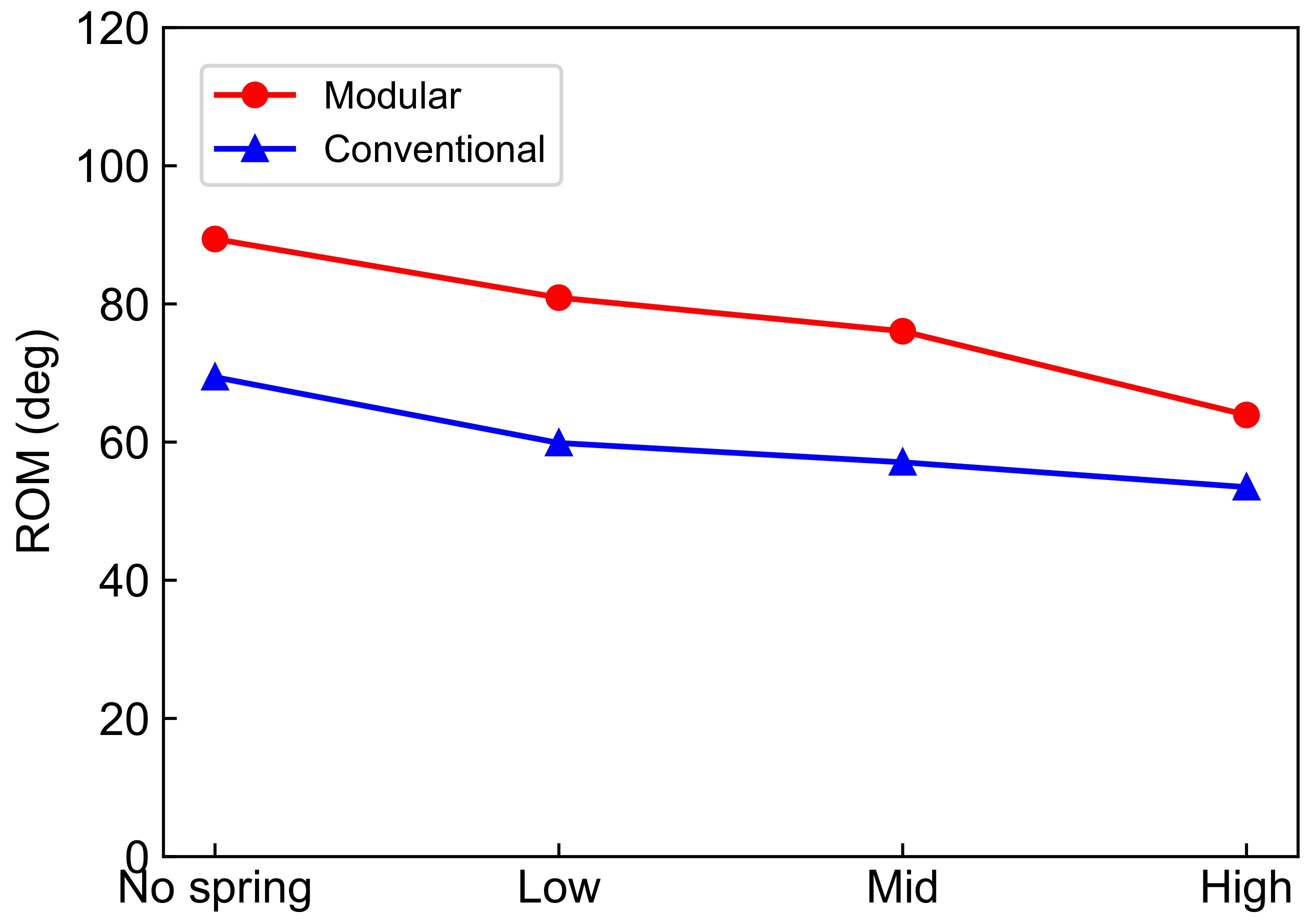
| Modular (deg, %) | 89.4, N/A | 80.9, −9.4 | 76.0, −14.9 | 63.9, −28.4 |
| Conventional (deg, %) | 69.4, N/A | 59.9, −13.7 | 57.1, −17.7 | 53.5, −22.9 |
Publisher’s Note: MDPI stays neutral with regard to jurisdictional claims in published maps and institutional affiliations. |
© 2022 by the authors. Licensee MDPI, Basel, Switzerland. This article is an open access article distributed under the terms and conditions of the Creative Commons Attribution (CC BY) license (https://creativecommons.org/licenses/by/4.0/).
Share and Cite
Kokubu, S.; Wang, Y.; Tortós Vinocour, P.E.; Lu, Y.; Huang, S.; Nishimura, R.; Hsueh, Y.-H.; Yu, W. Evaluation of Fiber-Reinforced Modular Soft Actuators for Individualized Soft Rehabilitation Gloves. Actuators 2022, 11, 84. https://doi.org/10.3390/act11030084
Kokubu S, Wang Y, Tortós Vinocour PE, Lu Y, Huang S, Nishimura R, Hsueh Y-H, Yu W. Evaluation of Fiber-Reinforced Modular Soft Actuators for Individualized Soft Rehabilitation Gloves. Actuators. 2022; 11(3):84. https://doi.org/10.3390/act11030084
Chicago/Turabian StyleKokubu, Shota, Yuanyuan Wang, Pablo E. Tortós Vinocour, Yuxi Lu, Shaoying Huang, Reiji Nishimura, Ya-Hsin Hsueh, and Wenwei Yu. 2022. "Evaluation of Fiber-Reinforced Modular Soft Actuators for Individualized Soft Rehabilitation Gloves" Actuators 11, no. 3: 84. https://doi.org/10.3390/act11030084