
A Twisted String, Flexure Hinges Approach for Design of a Wearable Haptic Thimble


Scuola Superiore Sant’Anna—Institute of Mechanical Intelligence (IIM), 56010 Pisa, Italy
*
Author to whom correspondence should be addressed.
Actuators 2021, 10(9), 211; https://doi.org/10.3390/act10090211
Submission received: 9 July 2021
/
Revised: 19 August 2021
/
Accepted: 24 August 2021
/
Published: 29 August 2021
(This article belongs to the Special Issue Actuators for Haptics)
Abstract
:Wearable haptic devices in the shape of actuated thimbles are used to render the sense of touch in teleoperation and virtual reality scenarios. The design of similar devices has to comply with concurring requirements and constraints: lightweight and compactness, intensity and bandwidth of the rendered signals. Micro-sized motors require a mechanical reduction to increase the output force, at the cost of noise and vibrations introduced by conventional gear reducers. Here we propose a different actuation method, based on a miniaturized twisted string actuator and a flexure hinge transmission mechanism. The latter is required to transmit and transform the pulling force of the twist actuator to a pushing force of the plate in contact with the fingerpad. It achieves a lightweight and noiseless actuation in a compact mechanism. In this work, we present design guidelines of the proposed approach, optimization, and FEM analysis of the flexure hinge mechanism, implementation of the prototype, and experimental characterization of the twist actuator measuring frequency response and output force capabilities.
1. Introduction
In recent years virtual reality (VR) has become an effective and affordable experience, due to advances in computer graphics and rendering devices: head-mounted displays and body tracking are nowadays integrated into high-resolution, wireless, and compact consumer products. These systems can be used for gaming, simulation, or training of personnel. They have also been proposed for rehabilitation systems based on virtual exercises [1,2] and serious games and robotic teleoperation [3]. Although many of the above VR applications involve manipulation tasks, sense of touch and haptic feedback are rarely included. The challenge is to find the most convenient compromise between wearable and comfortable haptic devices, and the intensity and richness of the haptic feedback such devices are capable to render.
Development of novel designs for wearable and compact haptic devices, worn at the hand and fingertips, is a rich research topic. Due to dimensional and mass constraints, usually each design is focused on rendering of a limited number of haptic cues, such as contact–no contact condition, modulation of grasping forces [4], contact orientation [5], area of contact [6], stretch and indentation [7], pressure by soft airbags interaction [8,9], thermal [10], and multi-modal feedback [11,12]. A comprehensive review of wearable haptic devices including a taxonomy can be found in [13].
Comfort and usability of fingertip haptic devices impose strict limits to mass and dimensions, due to user fatigue in prolonged use, interferences with other fingers, and encumbrance in the hand workspace. The design of the actuation system is then a trade-off between the quality of the rendered feedback (in terms of intensity, bandwidth, and signal-to-noise ratio) and the lightweight and compactness of the actuator. Usually, the actuation system is the heaviest part of a wearable fingertip haptic device. Electric micro-motors are widely used in fingertip haptic devices due to their compactness and simplicity of operation. Still, a mechanical gear reduction is typically used ([5,14]) in order to increase the output force. On the other hand, gear reduction introduces noise and vibrations in the rendered signals and severely limits the output bandwidth.
Alternative reduction mechanisms, such as pulleys and capstans, result in lower reduction ratios or heavy parts (i.e., miniaturized ball-screws). On the other side, twisted-string actuators have been proposed as a lightweight, simple, and compact reduction method. The operation principle consists of two tendons connecting the output shaft of a rotary motor to a sliding part: rotation of the motor twists the two tendons, thus shortening their total length, and finally producing a pulling force and then a movement of the moving part. The twist angle of the tendons, equal to the angular position of the motor, determines the linear distance between the motor and the output. The twist motion causes a shortening of the total tendons’ length and a linear motion of the output towards the motor. The transmission ratio can be related to the twist angle , the tendon radius r, and the tendon length , as shown in [15]:
where F is the pulling force and is the applied twisting torque. In [16] authors propose a control method making use of hybrid angular position and linear force sensing, for precise control of the twisted string output force and position.
This actuation principle obtains a reduction ratio compared to direct drive actuators, keeping the design compact and lightweight. On the other hand, it is mono-directional (only pulling forces are transmitted through the twisted string). The literature presents twisted string actuators implemented in robotic hands [17] and rehabilitation soft suits [18] and actuated gloves [19]. In these haptic interfaces, the twisted string actuators also introduce a degree of compliance (longitudinal stiffness of the twisted tendons) that resembles the series-elastic-actuator principle proposed in the literature for exoskeleton and similar motor-assistance devices. Haptic rendering devices using twisted string actuators have been also proposed, in the shape of desktop haptic devices, as in [20], and in [21], for the rendering of the contact stiffness.
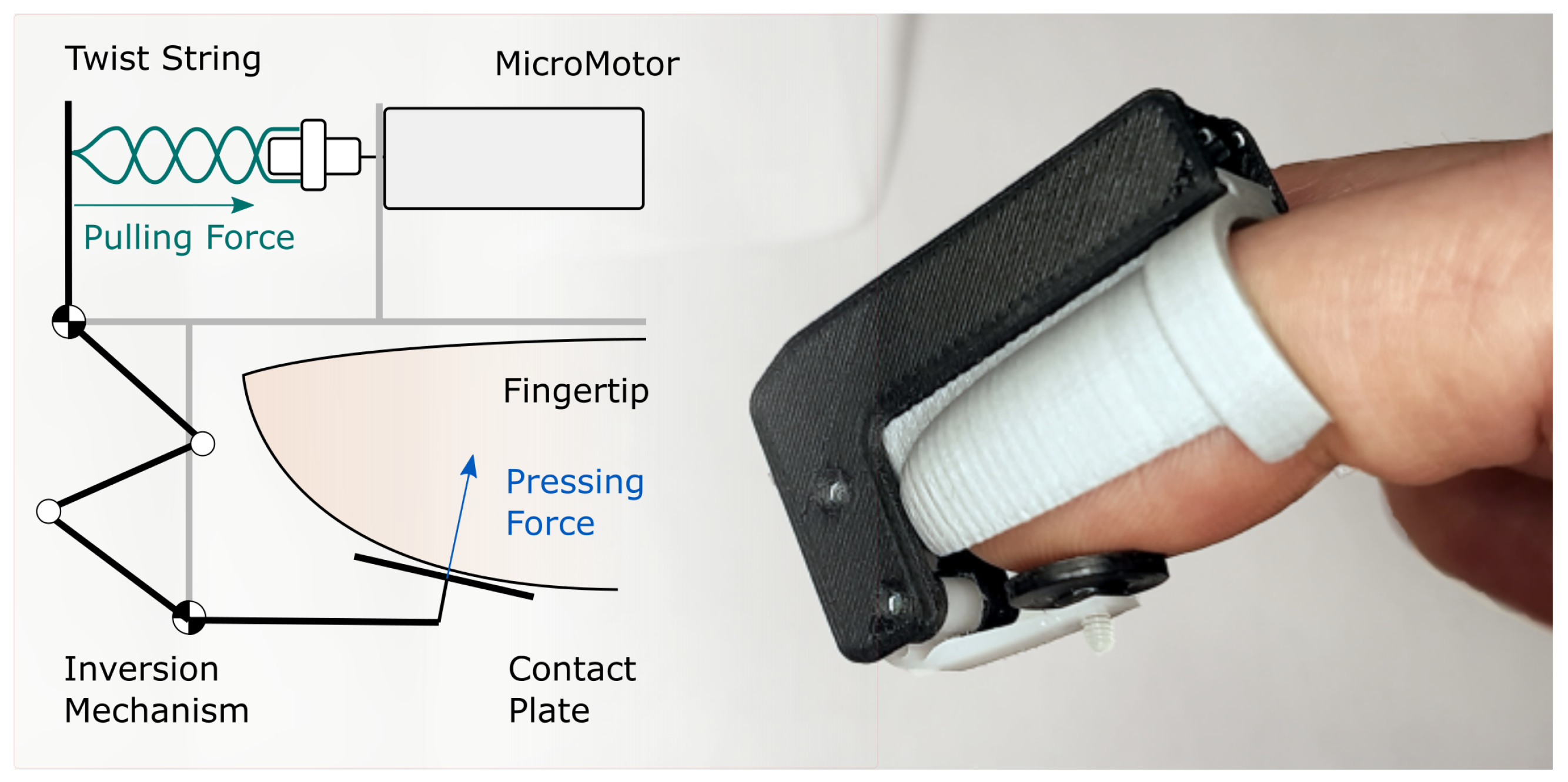
In this work, we present the design and development of a twisted string actuation system in a compact fingertip device (Figure 1). This paper is an extension of the preliminary design concept we presented in the conference manuscript [22]. Due to design constraints of fingertip wearable devices, the use of a miniaturized twisted string actuation also involved the development of a flexure hinges inverting mechanism for coupling the twisted string to the output plate. The final actuator and device design resulted in a very compact solution with a minimum amount of moving parts involved. In this work, we present the rationale of the approach and design guidelines, optimization, and FEM simulation of the flexure hinge mechanism, and experimental characterization of the implemented prototype.
2. The Twisted String and Flexure Hinge Approach
The twisted string solution has been chosen in place of other conventional actuation and reduction methods due to the absence of noise introduced in the output signals: vibration and backlash (generated i.e., by a miniaturized gearmotor) can easily degrade the quality of the haptic rendering. Additionally, the simplicity of the mechanism makes twisted string actuators suitable for miniaturization.
The intrinsic properties of the twist string actuator and the strict dimensional constraints of a fingertip haptic device made it convenient to develop a flexure hinge mechanism to transmit the output force from the twist string actuator to the plate in contact with the fingerpad.
In particular, implementation of a compact, single lever mechanism to transmit the force from the actuator to the fingerpad was not possible: a twist string actuator is capable of outputting only a pulling force, whereas the fingerpad plate has to be pushed against the fingertip. This had to comply with other constraints we tried to pursue in the design of a wearable and comfortable fingertip device: the preferred arrangement of the actuator is at the finger dorsum or, in any case, not below the fingerpad, in order to minimize encumbrance in the hand workspace. The same consideration was made for not encumbering finger sides, hence minimizing inter-finger interferences and allowing adaptation of the device to different finger sizes. In the proposed device, the thimble is made of soft polymer and can also be easily switched with larger thimbles without mechanical interferences. A first-type lever mechanism would occupy extra space in front of the fingertip, with extra-length dimensions at least equal to the distance between the fulcrum and the fingerpad plate. A second-type lever mechanism could not be implemented given the most convenient location of the fulcrum is in the proximity of the fingertip.
With the actuator placed at the finger dorsum, we proposed a design solution implementing a simple first-type lever mechanism for transmitting the movement to the fingerpad plate [22]. There, the twisted string had to be routed through a pulley placed in front of the upper arm of the mechanism, thus increasing the overall size of the device (stroke of the lever has to be considered in the overall dimensions). Moreover, the twisted string had to be directly routed around the pulley, thus increasing friction as opposed to the twisting action when the mechanism was loaded. A different approach implementing both a first-type and a third-type lever in the compact parallel mechanism was proposed in [23]: the mechanism was designed for a lead-screw actuator (coupled to a type-1 lever), capable to output forces in both directions, and for a direct drive actuator (coupled to a type-3 lever) with sharp routing angles of the miniaturized tendon transmission. The drawback of the lead-screw approach was considerably high friction, in particular when the screw is loaded, and higher complexity in terms of components.
A three-bar mechanism with rotoidal joints was then developed (as shown in Figure 1), able to transmit movement from a twist string actuator placed on the fingertip dorsum, to a compact moving plate underneath the fingerpad. Yet, it would require four rotoidal joints to be implemented.
Since the required displacement of the output plate is relatively small [14,24], a flexure hinge implementation of the inverting mechanism would provide the following advantages:
- Compact and lightweight mechanism with respect to rotoidal joints with shaft and bearings.
- Limited number of moving parts.
- No introduced friction or backlash, relevant for high-quality haptic feedback.
- Residual elastic force needed to move the plate in the out of contact direction.
2.1. Synthesis and Optimization of the Mechanism
In this section, an optimization method for the mechanism synthesis is proposed, taking into account desired transmission ratio and other design requirements, such as the flexure hinges’ strength and functional requirements.
As previously mentioned, the transmission mechanism employs four flexure hinges in place of the rotoidal joints shown in Figure 1 to allow force transmission from the twisted-string actuator to the finger. In general, angular displacement should be minimized when working with flexure hinges, in order to reduce the maximum strain. Hence an optimization method to minimize angular displacements has been developed.
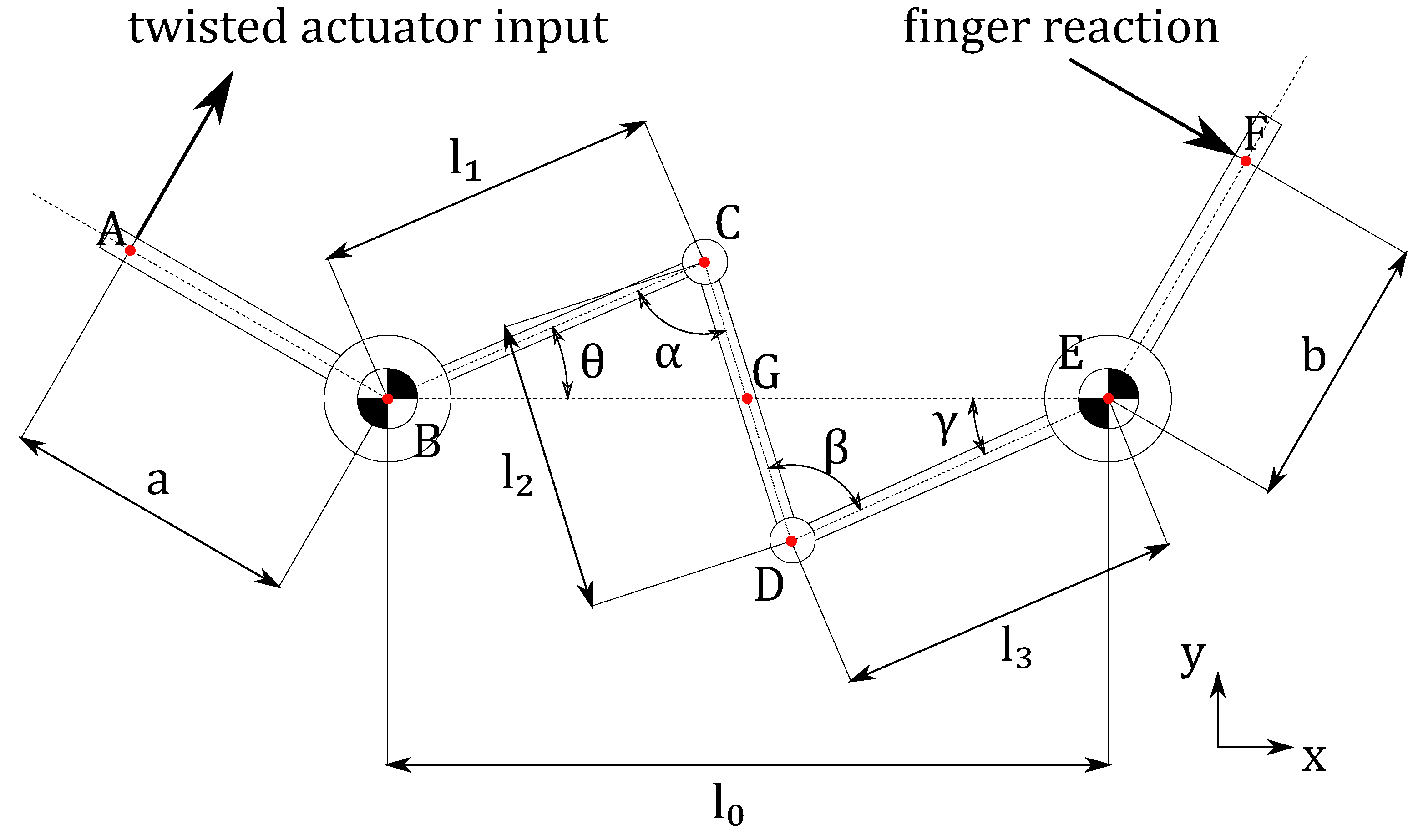
As a first step, we need the mechanism’s kinematic model, which allows us to determine both the transmission ratio and the angular displacements. By making the assumption that, for small displacements, flexure hinges can be treated as rotary joints, we can sketch a concept version of our mechanism as in Figure 2.
The simplified mechanism can be described using a minimum set of geometrical parameters, that are the lengths of its input leverage a, its output leverage b, and the intermediate leverages . , , and the distance between the two fixed points B and E . Then we define the flexural hinges angles , , , , that are constrained kinematic variables since the mechanism has only a degree of freedom.
The transmission ratio , defined as the ratio between the output linear motion towards the finger and the input linear motion imposed by the twisted string actuator, can be calculated—linearizing it to first order-as:
This equation shows that the transmission ratio is the product of a fixed part, which depends on the input and output leverages lengths a and b, and a variable (the kinematics is nonlinear because of sine and cosine functions are involved, so it is already known that the angular transmission ratio would be dependent on the mechanism configuration) part, which depends on the angular transmission ratio.
We can simplify our problem if we only look at the angular transmission ratio; this function is adimensional, and this gives us the hint that we can eliminate one length parameter from the optimization. In fact, the angles and would be the same both for large and small version of the mechanism if the shape factors between the leverages lengths are kept constant. For this reason we can normalize the length parameters:
At this point, the next step is determining the relation between the system input angle and the output angle . To do that, it is first necessary to define the kinematics of points C and D with respect to the fixed points B and E:
From these vectors, it is possible to calculate CD as a function of and . However, since CD has a constant length , we can find a constraint relation between and . The resulting equation is:
To speed up the algorithm execution it is necessary to achieve the analytical solution of Equation (5). Since small angular displacements are expected, it is fair to assume that both gamma and theta are within the range in the mechanism workspace. The solution is given by:
Moreover, we are also interested in monitoring the values of and angles in our optimization: in fact, since all the rotary joints will actually be flexure hinges, it is important to avoid excessive angular displacements that could compromise the functionality of flexure hinges. The angle can be easily calculated by using Carnot’s Theorem on both triangles CBE and CDE, that allow us to find, respectively, CE as a function of and CE as a function of . After some calculations, value is given by:
Finally, can be easily calculated as a function of the other three angles. In fact, if we look at triangles CGB and EGD, we can see that they have a common angle . The sum of angles in a triangle is always equal to , thus we can write the equation:
The mechanism’s kinematics are fully determined. The angles and the transmission ratio depend only on five design parameters, which are the input and output leverages lengths, a and b and the shape factors of the intermediate leverages, , , and .
To further improve this analysis, it is important to introduce the concept of workspace. Most likely, the mechanism will operate within limited angular ranges, which means angular displacements of flexural hinges remain limited, too. Thus, the optimization method should analyze the device performance only within the device workspace.
We imposed workspace limits on the basis of actuating requirements, fingertip dimensions, and overall desired encumbrance of the device. In particular, we defined a required maximum displacement of the output plate equal to 3 mm, considering 1 mm clearance for the out-of-contact condition, plus 2 mm indentation, on the basis of previous findings [24]. Regarding lengths of the input and output links and distance of the points A and B, a, b, and were fixed to , , and respectively, on the basis of the dimensions and arrangement of components around the finger as shown in Figure 1. Hence, they are specific to the proposed design implementation and included in the optimization process. Then, we can calculate the angular range needed for the angle:
Still, there is not a clear method to choose the value—or equivalently, —which means, in other words, that there is not a clear method to decide what is the best starting point for the workspace, angular range, to be calculated.
Thus, the value will be the result of the optimization method, together with the remaining parameters: , , and .
At this point we know what are the values that we want to optimize, and we know what are our objectives: the flexure hinges should not not undergo excessive strains, and the angular transmission ratio should be the closest possible to 1 in any point of the workspace. To reach this goals by means of an optimization algorithm, a cost function must be defined, which will be minimized.
Let us define first an helper function, which is a vector with all the unknown angular ranges.
Then, we can calculate explicitly the angular transmission ratio. By differentiating Equation (5), we obtain:
where we can see that the angular transmission ratio depends on the configuration, too. Finally we can define the cost function:
The cost function is the sum of two terms: the first one is the mean value of the ratios between the variance of the helper function h and its mean. In fact, h is the vector with the unknown angular ranges, so minimizing the variance of the h function means that we want all the angular ranges to be equal. We need to normalize this term so we can compare it to the second one, which is adimensional. We used the mean for this purpose. The second term is the variance of the difference between the desired transmission ratio—which is 1—and its actual value, computed for all the values of within the workspace. The closer to one is the angular transmission ratio within the whole workspace, the lower the second term of the cost function will be.
To obtain a feasible solution, and to narrow the search field for our optimization method, it is important to introduce the needed constraints. The most obvious constraint is on the values of , , and , which must be within the range . Then, the value of the angle is constrained within the range , because the angle should respect the conditions for the solution of the Equation (6).
Moreover, as a design choice, we put a constraint on the maximum extension of the mechanism in the y direction, as shown in Figure 2, that should be lower than .
There are several constrained optimization algorithms that could be suitable for the described problem; we choose to employ the genetic algorithm because, even if it is a heuristic method, it is not affected by local minima and it is less affected by the starting conditions if mutations between subsequent generations are correctly inserted in the algorithm.
The implementation is quite straightforward: the parameters that we need to optimize will be the genes of the individuals in a given population, with a cost function as defined in Equation (12) that determines the fitness value of each individual. We ran the algorithm using MATLAB with the settings reported in Table 1 and with an initial population which was randomly generated—respecting all the aforementioned constraints—obtaining a fitness value of 1.281 × 10 for the best individual output by the algorithm. The best individual is represented by the following parameters—genes:
2.2. FEM Analysis of the Flexure Hinges
A FEM analysis was conducted to simulate the behavior of the mechanism implementation with flexure hinges in place of rotoidal joints. In particular, we studied two different loading conditions: with the fingerpad plate moving in free air, and with the fingerpad plate constrained to a fixed position.
The mesh generated for the FEM used parabolic tetrahedral elements and had 42,628 elements. The flexure hinge was constrained in two points (shown in Figure 3, left). The first mode of vibration resembles deformation of the mechanism when loaded by the actuator in its working conditions, and is informative of the output bandwidth the actuator can transmit through the mechanism to the output plate.
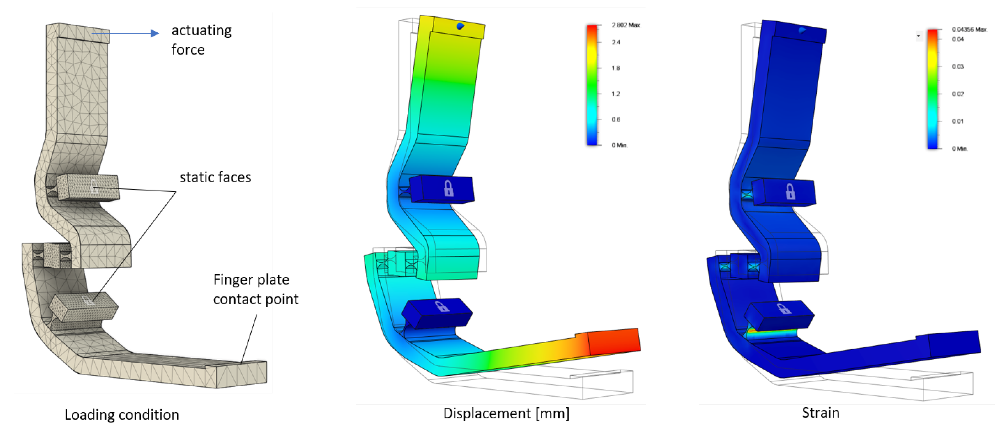
The condition with the plate moving in free air is informative of the elastic force of the mechanism (which is opposed to the pulling force of the twisted string), and of the strain of the flexure hinges when the lever is moved to full stroke. Results of the FEM analysis with the thickness of the flexure hinges at 0.1 mm is shown in Figure 3. The input force was set to 0.26N in order to measure a displacement of the moving plate of 3.0 mm, equal to the maximum stroke considered for the device. The measured maximum strain is equal to 0.041.
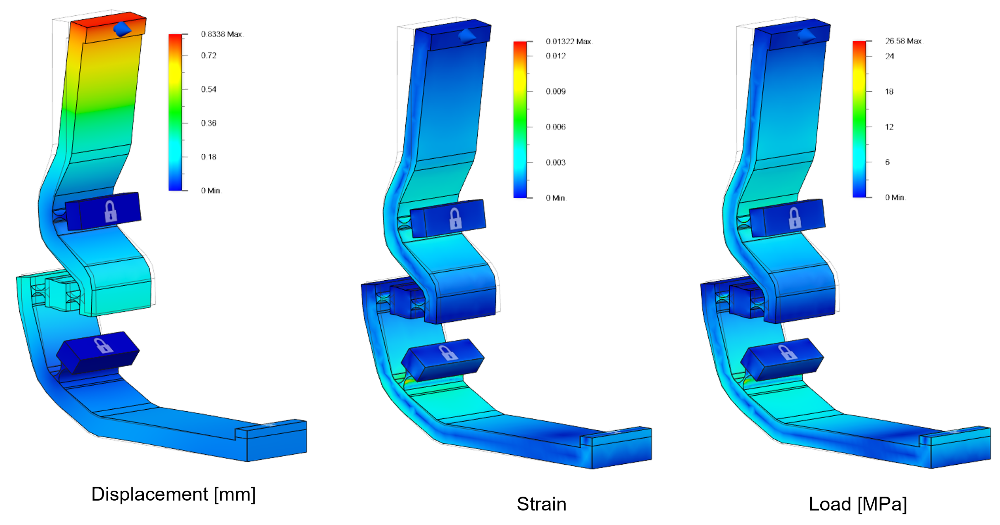
The condition with the constrained output plate provides information about how forces are transmitted from the input lever to the fingerpad plate, and about stress of the flexure hinges in this working condition. Results are shown in Figure 4, with 1 N loading force. Measured maximum strain was 0.013 and maximum stress was 26.6 MPa.
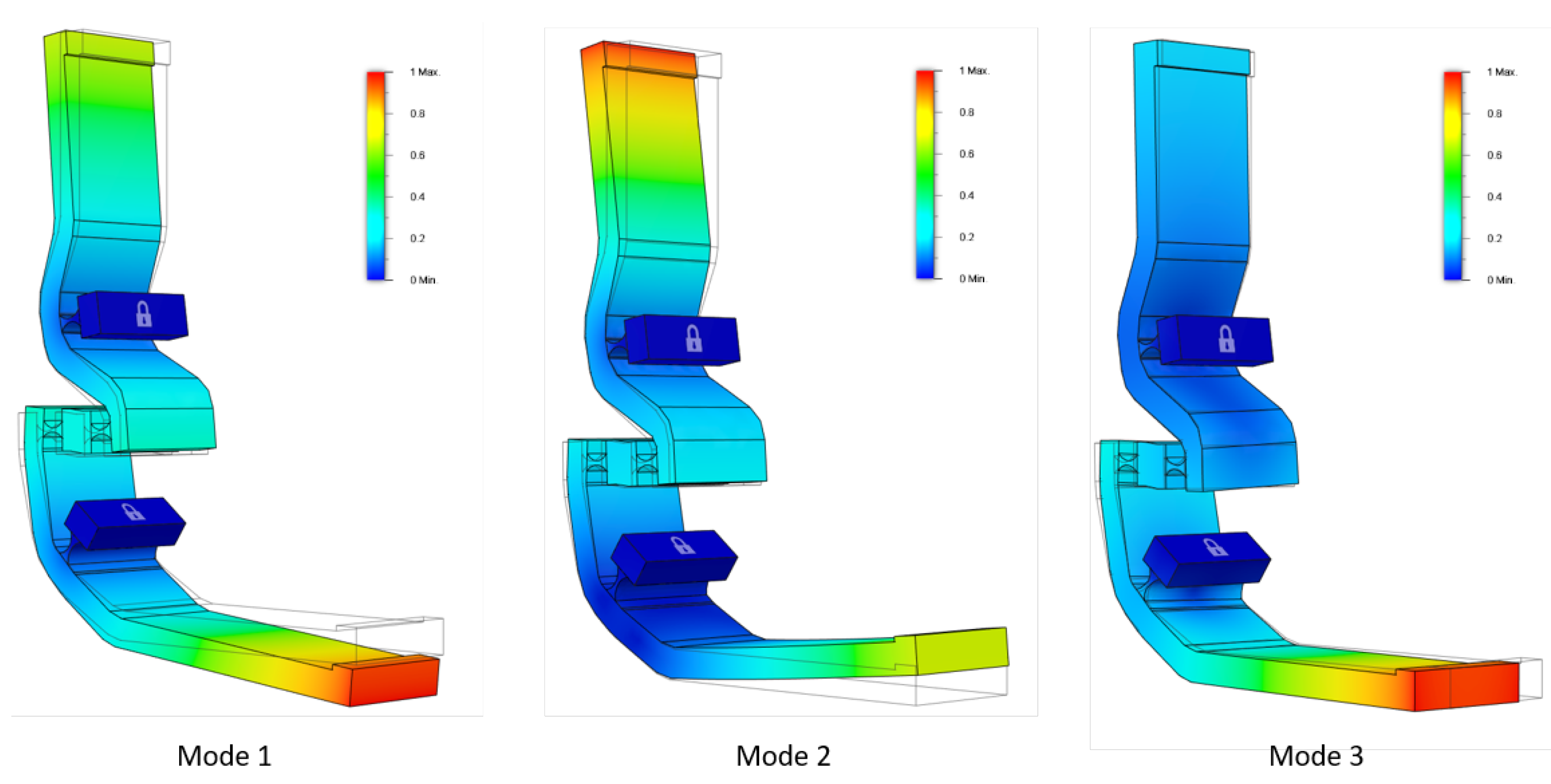
A modal analysis was conducted to simulate modal frequencies of the mechanism, in order to better evaluate resonances and output bandwidth of the device in haptic rendering. Figure 5 shows the first three modes of vibration, corresponding to 175 Hz, 1122 Hz, and 1205 Hz, respectively with 0.1 mm thickness of the flexure hinges.
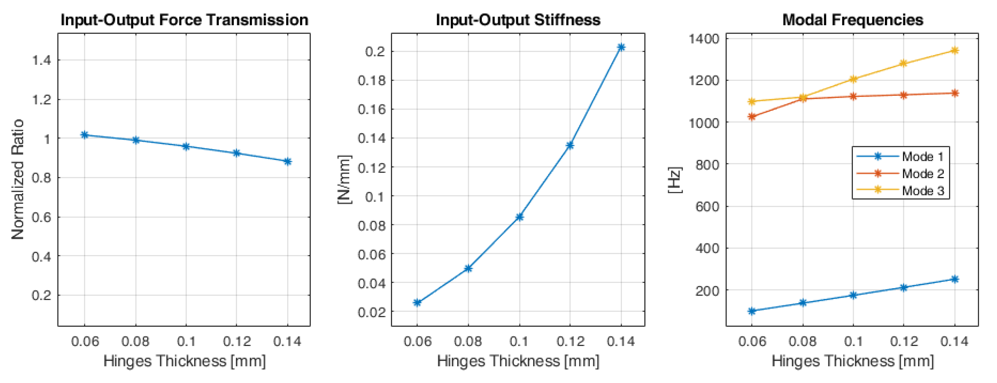
Then, the FEM analysis has been iterated at varying thickness of the flexure hinges: the range between 0.06mm and 0.14mm was explored (equal thickness for all the four flexure hinges). The left graph in Figure 6 reports the ratio between input and output force transmission: it refers to the ratio between the linear force applied by the twisted string actuator, and the linear output force measured at the moving plate in contact with the finger. In the CAD model, the length of the input and output links (“a” and “b” respectively in the kinematic scheme of Figure 2 were chosen in order to have a theoretical input–output force reduction equal to 1. The middle graph in Figure 6 shows the residual stiffness of the flexure hinge mechanism: it is computed as the output displacement of the moving plate divided by the input force when the mechanism is moving in free air. The right graph in Figure 6 shows frequencies of the first three modes of vibration of the mechanism (shown in Figure 5): the first mode is directly related to the actuated degree of freedom of the mechanism and shows the lowest resonant frequency.
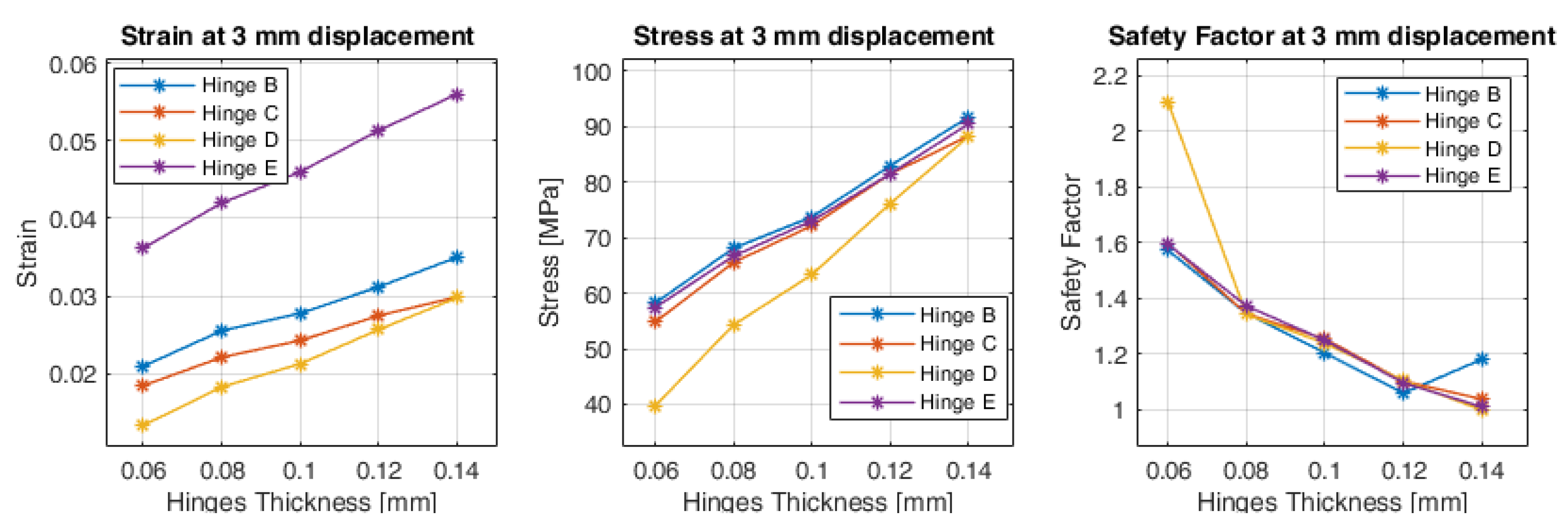
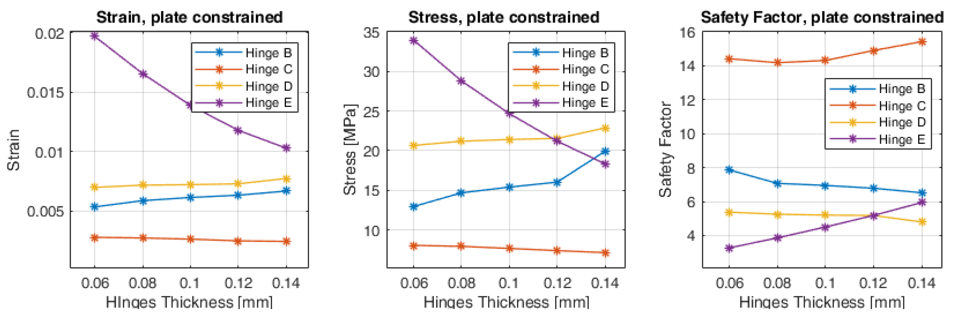
The graphs shown in Figure 7 and Figure 8 provide information about strain, stress (Von Mises), and safety factor of each flexure hinge in the two different loading conditions: with the plate moving in free air and at 3 mm displacement, and with the plate constrained with 1 N input force. For each flexure hinge, the measurement point was placed on the surface of the thinnest point of the hinge. The condition at 3 mm displacement imposes higher deformation of the flexure hinges, thus increasing the strain and reducing the safety factor as the thickness increases. Strain is particularly higher for the flexure hinge at point E, although the loading directions result in a similar safety factor with respect to the other hinges. Conversely in the loading condition with the constrained output plate, the higher thickness of the flexure hinges diminishes the strain, especially for the flexure hinge at point E, and the safety factor is consequently improved.
3. Design and Implementation of the Twisted String Haptic Thimble
The proposed approach has been applied for the design of a fingertip haptic device, rendering cutaneous force feedback (Figure 1) through a moving plate in contact with the finger. The design of the device followed considerations presented in Section 2.
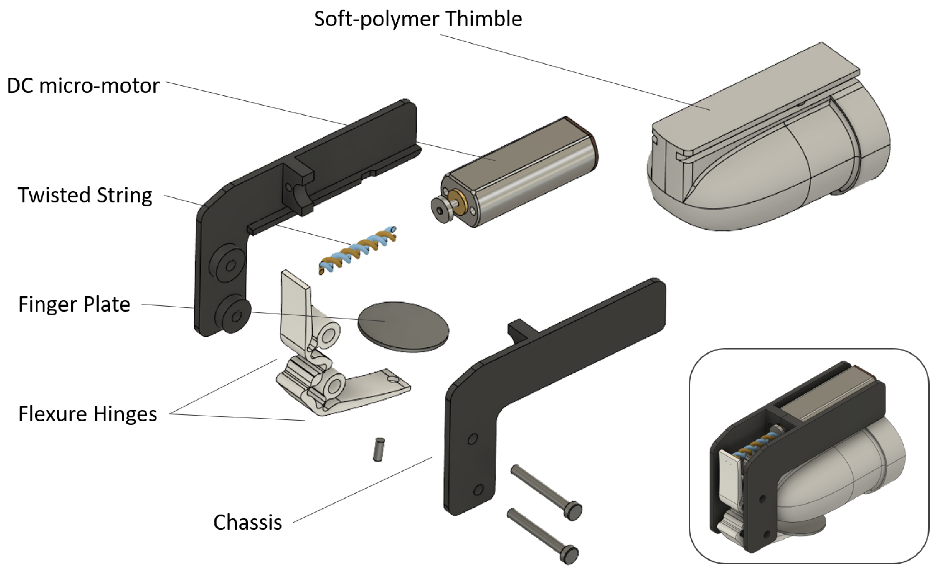
An overview of the final design and placement of the different components is shown in Figure 9. The actuator has been placed at the finger dorsum, and the whole device design has been studied to minimize lateral interference with other fingers and interference with the hand workspace. The final device features 36 mm length, 21 mm height, and 10 mm width (width of the main body excluding the interchangeable thimble). The total mass is 8.6 g. The slim design at the sides of the device minimizes mechanical interferences between fingers (Figure 9), also, it allows switching between thimbles of different sizes. The thimble was 3D printed in TPU (Thermoplastic Polyurethane, Ultimaker TPU 95A), a soft polymer providing compliance to the specific user’s finger shape. Different thimble sizes were fabricated by an FDM (Fused Deposition Modeling) 3D printer, resulting in a compliant and stable fit of the thimble to different finger sizes, not requiring additional fastening elements. A slider mechanism allows the easy and rapid switch between different thimbles. The flexure hinge mechanism was CNC machined in one single part from a 5 mm thick Delrin (POM polymer) sheet, using a 1 mm diameter end-mill. The twisted string and flexure hinge approach allowed us to reduce the complexity of the device, minimizing the number of moving parts and also reducing the total number of components: just seven parts are required to be assembled (thimble, two parts for the chassis, one flexure hinge, contact plate, the twisted string, and the DC micro-motor) as shown in Figure 10.
Driving electronics are intended to be separated from the fingertip device, to accommodate a board with wireless connectivity and a battery with sufficient capacity: in [1] we used a compact enclosure worn at the wrist.
4. Experimental Characterization
The developed prototype was tested at the bench to assess static and dynamic performances that are relevant for haptic rendering. In detail, we focused on the evaluation of the maximum static output force and rendering dynamics in terms of step and frequency response. An external compact force sensor (Optoforce 10 N with a resolution of 1 mN) was mounted on a holder in place of the soft-polymer thimble to measure the output forces. The controller of the haptic device was implemented on a microcontroller board (Teensy 3.6) that runs the low-level control loop at 1 KHz, whereas the motor was driven through a compact dual H-bridge (Texas Instruments DRV8835).
Communication with a host PC was implemented through USB communication. Reference signals for the high-frequency test were buffered onboard the microcontroller.
For both static and dynamic evaluation experiments, the contact plate was positioned at the contact threshold with the force sensor. In more detail, in the quasi-static experiment, a slow voltage reference ramp was commanded to the motor for ten repetitions. After data collection, a stress test was performed to evaluate the effect on the device of intensive usage. The stress test consisted in performing about 10,000 step cycles with approximately 2.5 mm displacement of the moving plate in free air, repeated with a 1 s period. As a qualitative result, the haptic thimble did not report evident signs of wearing or breaking.
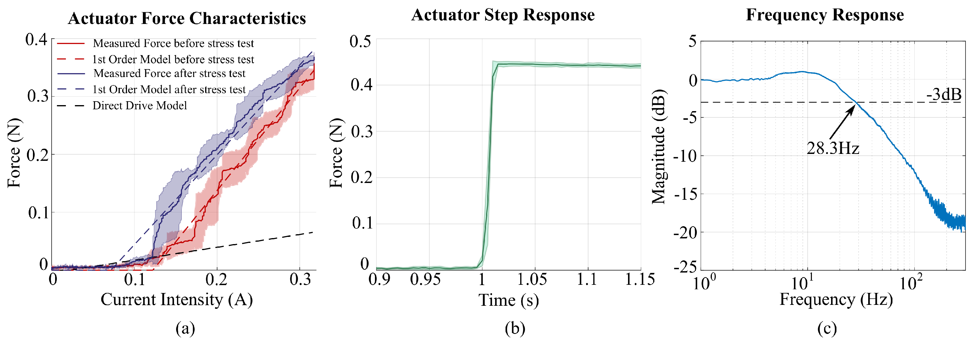
The obtained current intensity to force characteristics are shown in Figure 11a: the red ones refer to recordings before the stress test, whereas the blue ones refer to results collected after the stress test. The shaded areas represent the standard deviations. In the same figure, we reported the 1st Order Regression Model of the output current-to-force characteristics with dotted lines (red and blue) and the ideal linear current-to-force characteristic (Direct Drive Model), computed from motor parameters and simulating direct coupling of the motor to the contact plate mechanism considering a 1 mm radius pulley (black dotted line). The comparison of the two measured characteristics with respect to the ideal one of the Direct Drive Model highlights the amplification of the output force obtained by the twisted string transmission.
Before the stress test, the current-to-force characteristic exhibited a dead-zone section in the range 0 to 0.122 A and a monotonic section in the range to 0.32 A with an estimated 1st order force constant of 1.77 N/A. In comparison, the computed force constant for the Direct Drive Model was 0.222N/A.
The comparison of the two measured characteristics before and after the stress test highlights no performance decline due to fatigue of the flexure hinges. Conversely, the measured performance was slightly increased: the dead-zone was in the range 0 to 0.073 A and a monotonic relation in the range to 0.32 A with an estimated 1st order force constant of 1.55 N/A. The reduction of the dead-zone was probably due to lower static friction at the bushings of the micro motor shaft after the repeated movement cycles.
The dynamic experiments consisted of step response and frequency response evaluation. For the response, the motor was driven by a sequence of voltage reference steps (5 V nominal, corresponding to a current intensity of 0.32 A). Each input voltage step was provided starting from an untwisted state of the strings. Results in Figure 11b show the maximum output force of the step response (0.45 N) was higher than the value obtained for the ramp reference at the same current intensity of the motor (0.33 N). It indicates a non-linear behavior of the twisted string during loading, as similarly highlighted in the quasi-static experiment. Moreover, the estimated slew rate of the device was 0.015 s. The frequency response was evaluated by stimulating the device with a voltage chirp reference signal in the range of 1–300 Hz. The system exhibited second-order dynamics with a cutoff frequency of 28.3 Hz.
5. Discussions
The design of fingertip haptic devices has to comply with different geometrical and dynamic constraints, such as limited mass for comfortable prolonged use and limited size and inter-finger mechanical interferences. On the other hand, high maximum forces applied at the fingerpad, similar to the amplitude of the force interaction occurring during manipulation and grasping, are required for rendering realistic force feedback. Here, we proposed an actuation method making use of a twisted string actuator and a flexure hinge mechanism to obtain mechanical reduction: it can be miniaturized for implementation in a miniaturized fingertip device, and does not introduce noise and vibrations as conventional gear reductions. This is a fundamental advantage in haptic devices since the sensitivity of fingerpad mechanoreceptors to high-frequency cues is relevant.
The overall kinematics of the inverting mechanism, required to transmit and invert the direction of movement from the twisted string to the moving plate, was firstly examined and optimized through a genetic algorithm. By envisaging its implementation by means of flexure hinges, the optimization was then conducted in order to minimize peak deformation for each flexure hinge. The obtained results (bar lengths and starting pose of the mechanism) were used to implement a refined CAD model of the flexure hinge mechanism. The FEM simulation was then conducted in order to better understand the behavior of the mechanism. In particular, different thicknesses of the flexure hinges provide different behavior of the mechanism in terms of force residual stiffness, bandwidth, and safety factor. The first exploratory FEM analysis was conducted with a thickness of the flexure hinges of 0.1 mm, which was compatible with conventional CNC machining techniques. It validated deformation points (flexure hinges with respect to the links of the mechanism) and displacement direction of the output plate when actuated. Additionally, the modal analysis provided information about the modes of vibration: frequency of the first mode (matching the actuated d.o.f of the device) is informative of the bandwidth of the achievable haptic rendering.
The following FEM analyses showed the simulated behavior of the mechanism at a varying thickness of the flexure hinges (from 0.06 to 0.14 mm). The ratio of the input–output force transmission was minimally affected: a reduction ratio from 1.016 to 0.883 was measured due to the increased stiffness of the hinges. Conversely, residual stiffness of the mechanism and modal frequencies were more noticeably affected: stiffness increased from 0.027 N/mm to 0.214 N/mm. An elastic force is needed to move the plate in the out-of-contact direction (whereas the twist string actuator can only pull in one direction), on the other side at a maximum stroke the elastic force is opposing the actuator, thus diminishing the output maximum force.
Results of the FEM analyses of the joints provided information about strain, stress, and safety factor in different loading conditions. The first condition examined the free motion of the mechanism up to the maximum stroke (3 mm displacement of the moving plate), where maximum deformation of the flexure hinges is achieved. In this condition, increasing the thickness of the hinges reduces the safety factor. Values of the safety factor are relatively close for all the hinges: at 0.1 mm thickness, hinges are between 1.2 minimum, 1.24 maximum safety factor. At 0.14 mm thickness, the safety factor for three out of four hinges approaches the critical value of 1 (0.979 minimum, 1.19 maximum). The second condition, involving a 1 N loading force with a constrained plate, showed a more variable behavior for the different hinges. In particular, the hinge E resulted in more stress than the others especially for reduced values of thickness. However, the minimum level of safety factor in this condition was not critical (3.2 safety factor for the E hinges and 0.06 mm thickness).
Regarding the frequency of the first mode of vibration, it falls within the wide bandwidth of haptic rendering signals (from static to about 300 Hz). However, as evidenced by following discussions on experimental results, the twisted string actuation appears suitable for static to low-frequency haptic rendering.
Experimental characterization of the device results showed that the nominal output force was 0.45 N, with a bandwidth of 28.3 Hz, which is acceptable for a fingertip haptic device. In comparison, works presented in [5,14,25], making use of miniaturized RC servo motors for fingertip haptic devices, resulted in a bandwidth below 10 Hz. On the other side, devices making use of direct-drive motors such as voice coil ([26]), achieve frequencies up to 250 Hz still with an increased total mass (30 g). As a relevant result from the stress test (10,000 step cycles) the flexure hinge mechanism reported no evident signs of wearing or breaking and no deterioration in the measured performances.
The reduction ratio obtained in the current device implementation is about and depends on the chosen string diameter. The string thickness was selected as a trade-off between the reduction ratio and reversibility of the twisted string in the unloading phase. In fact, a thicker string results in a more reversible solution although with a lower reduction gain. As a further design development, a miniaturized position sensor might be integrated in order to control the plate position in a closed-loop. This would allow for higher reduction ratios and for diminishing non-linearities due to friction: in detail, static friction was about 25% of the output force.
The final design of the fingertip device achieved good results in terms of total mass and lateral dimensions (10 mm total width excluding the interchangeable soft thimble, 8.6 g total mass) with no parts arranged at the sides of the finger. This solution avoids inter-finger interferences and allows mounting and rapid change of different thimbles sizes, improving wearability and reliable fixing of the device to the finger. An additional advantage of the proposed twisted string and flexure hinge solution is that it reduces the complexity of the final device in terms of the number of components and the number of moving parts. The whole device is composed of just seven parts and five mounting screws. Control of the twisted string actuator requires additional investigation due to its non-linear behavior. To overcome this, future works will explore the control of the device, in terms of closed-loop control or, alternatively, different twisted string configurations (varying tendon size and twisting diameter) to explore feed-forward control possibilities. The latter solution would preserve the simplicity and compactness of the device.
6. Conclusions
In this work we have presented an actuation method for miniaturized haptic devices based on twisted strings: it consists of a twisted string actuator and of an optimized flexure hinge mechanism, required to revert the movement direction from the actuator to the fingerpad plate. Advantages of the twisted string method with respect to alternative actuators (i.e., direct-drive voice coils or gear-reduced dc motors) consist in the simple and compact force amplification mechanism, which does not introduce noise or backlash typical of gear reduction. The absence of noise and backlash is useful in haptic feedback devices, where perception can be easily disrupted by spurious interferences.
Given design constraints imposed by wearable fingertip devices, we developed and optimized a flexure hinge inverting mechanism to couple the twisted string actuator to the moving plate in contact with the finger. In this work, we presented an in-depth optimization and FEM analysis of the developed flexure hinge mechanism, which, in the proposed approach, is the key factor to implement the twisted string actuation in a compact fingertip device. Results of the optimization and FEM analysis showed the approach can comply with the design constraints of a real device implementation.
Regarding the final design, the actuation method reduced the number of components required for the whole device: the final device design result was compact and lightweight, and made of just seven parts (plus five mounting screws). The slim actuating mechanism improved the wearability of the device, allowing the implementation of switchable custom thimbles, in order to better comply with different finger dimensions.
Tests of the implemented prototype at the bench showed how the proposed approach is effective in rendering static to low-frequency cutaneous force feedback: the twisted string approach obtains a movement reduction, with relatively high static output forces, without introducing noise and backlash as for typical miniaturized gear reducers. On the other hand, the resulting bandwidth of the device is limited to 28.3 Hz. This allows rendering of common haptic features such as modulation of the grasping force, still, it prevents the rendering of other high-frequency haptic features, such as vibrations and textures. Methods to overcome this limit involve the coupling of a separate actuator (in series or in parallel, as proposed in [23]) dedicated to the rendering of the high-frequency components.
Author Contributions
Conceptualization, Mechanism Design and Implementation, FEM analysis, Writing, Funding: D.L.; Mechanism optimization and synthesis, Writing: L.T.; Experimental Characterization and Control, Writing: D.C.; Review and Editing, Funding: A.F. All authors have read and agreed to the published version of the manuscript.
Funding
This work was supported by the Project “TELOS—Tailored neurorehabilitation thErapy via multi-domain data anaLytics and adapative seriOus games for children with cerebral palSy”, which is funded under the call “Bando Ricerca Salute 2018” of Tuscany Region, Italy (CUP J52F20001040002).
Conflicts of Interest
The authors declare no conflict of interest.
References
- Bortone, I.; Barsotti, M.; Leonardis, D.; Crecchi, A.; Tozzini, A.; Bonfiglio, L.; Frisoli, A. Immersive Virtual Environments and Wearable Haptic Devices in rehabilitation of children with neuromotor impairments: A single-blind randomized controlled crossover pilot study. J. Neuroeng. Rehabil. 2020, 17, 1–14. [Google Scholar] [CrossRef]
- Gutiérrez, Á.; Farella, N.; Gil-Agudo, Á.; de los Reyes Guzmán, A. Virtual Reality Environment with Haptic Feedback Thimble for Post Spinal Cord Injury Upper-Limb Rehabilitation. Appl. Sci. 2021, 11, 2476. [Google Scholar] [CrossRef]
- Klamt, T.; Schwarz, M.; Lenz, C.; Baccelliere, L.; Buongiorno, D.; Cichon, T.; DiGuardo, A.; Droeschel, D.; Gabardi, M.; Kamedula, M.; et al. Remote mobile manipulation with the centauro robot: Full-body telepresence and autonomous operator assistance. J. Field Robot. 2020, 37, 889–919. [Google Scholar] [CrossRef] [Green Version]
- Solazzi, M.; Frisoli, A.; Bergamasco, M. Design of a novel finger haptic interface for contact and orientation display. In Proceedings of the Haptics Symposium, Waltham, MA, USA, 25–26 March 2010; pp. 129–132. [Google Scholar]
- Chinello, F.; Malvezzi, M.; Pacchierotti, C.; Prattichizzo, D. Design and development of a 3RRS wearable fingertip cutaneous device. In Proceedings of the 2015 IEEE International Conference on Advanced Intelligent Mechatronics (AIM), Busan, Korea, 7–11 July 2015; pp. 293–298. [Google Scholar]
- Fani, S.; Ciotti, S.; Battaglia, E.; Moscatelli, A.; Bianchi, M. W-FYD: A wearable fabric-based display for haptic multi-cue delivery and tactile augmented reality. IEEE Trans. Haptics 2017, 11, 304–316. [Google Scholar] [CrossRef] [Green Version]
- Leonardis, D.; Solazzi, M.; Bortone, I.; Frisoli, A. A wearable fingertip haptic device with 3 DoF asymmetric 3-RSR kinematics. In Proceedings of the 2015 IEEE World Haptics Conference (WHC), Evanston, IL, USA, 22–26 June 2015; pp. 388–393. [Google Scholar]
- Sonar, H.A.; Gerratt, A.P.; Lacour, S.P.; Paik, J. Closed-loop haptic feedback control using a self-sensing soft pneumatic actuator skin. Soft Robot. 2020, 7, 22–29. [Google Scholar] [CrossRef]
- Feng, Y.L.; Fernando, C.L.; Rod, J.; Minamizawa, K. Submerged haptics: A 3-DOF fingertip haptic display using miniature 3D printed airbags. In Proceedings of the ACM SIGGRAPH 2017 Posters, Los Angeles, CA, USA, 30 July–3 August 2017; pp. 1–2. [Google Scholar]
- Gallo, S.; Rognini, G.; Santos-Carreras, L.; Vouga, T.; Blanke, O.; Bleuler, H. Encoded and crossmodal thermal stimulation through a fingertip-sized haptic display. Front. Robot. AI 2015, 2, 25. [Google Scholar] [CrossRef] [Green Version]
- Gabardi, M.; Chiaradia, D.; Leonardis, D.; Solazzi, M.; Frisoli, A. A high performance thermal control for simulation of different materials in a fingertip haptic device. In International Conference on Human Haptic Sensing and Touch Enabled Computer Applications; Springer: Heidelberg, Germany, 2018; pp. 313–325. [Google Scholar]
- Wang, D.; Ohnishi, K.; Xu, W. Multimodal Haptic Display for Virtual Reality: A Survey. IEEE Trans. Ind. Electron. 2019, 67, 610–623. [Google Scholar] [CrossRef]
- Pacchierotti, C.; Sinclair, S.; Solazzi, M.; Frisoli, A.; Hayward, V.; Prattichizzo, D. Wearable haptic systems for the fingertip and the hand: Taxonomy, review, and perspectives. IEEE Trans. Haptics 2017, 10, 580–600. [Google Scholar] [CrossRef] [PubMed] [Green Version]
- Leonardis, D.; Solazzi, M.; Bortone, I.; Frisoli, A. A 3-RSR haptic wearable device for rendering fingertip contact forces. IEEE Trans. Haptics 2016, 10, 305–316. [Google Scholar] [CrossRef] [PubMed]
- Jeong, S.H.; Kim, K.S. A 2-speed small transmission mechanism based on twisted string actuation and a dog clutch. IEEE Robot. Autom. Lett. 2018, 3, 1338–1345. [Google Scholar] [CrossRef]
- Rodriguez, A.S.M.; Hosseini, M.; Paik, J. A hybrid control strategy for force and precise end effector positioning of a twisted string actuator. IEEE/ASME Trans. Mechatron. 2020. [Google Scholar] [CrossRef]
- Cho, K.H.; Song, M.G.; Jung, H.; Park, J.; Moon, H.; Koo, J.C.; Nam, J.D.; Choi, H.R. A robotic finger driven by twisted and coiled polymer actuator. Electroactive Polymer Actuators and Devices (EAPAD) 2016. Int. Soc. Opt. Photonics 2016, 9798. [Google Scholar] [CrossRef]
- Hosseini, M.; Meattini, R.; Palli, G.; Melchiorri, C. A wearable robotic device based on twisted string actuation for rehabilitation and assistive applications. J. Robot. 2017, 2017. [Google Scholar] [CrossRef] [Green Version]
- Hosseini, M.; Sengül, A.; Pane, Y.; De Schutter, J.; Bruyninck, H. Exoten-glove: A force-feedback haptic glove based on twisted string actuation system. In Proceedings of the 2018 27th IEEE International Symposium on Robot and Human Interactive Communication (RO-MAN), Nanjing, China, 27–31 August 2018; pp. 320–327. [Google Scholar]
- Pepe, A.; Hosseini, M.; Scarcia, U.; Palli, G.; Melchiorri, C. Development of an haptic interface based on twisted string actuators. In Proceedings of the 2017 IEEE International Conference on Advanced Intelligent Mechatronics (AIM), Munich, Germany, 3–7 July 2017; pp. 28–33. [Google Scholar]
- Van, Q.H.; Harders, M. Augmenting contact stiffness in passive haptics—Preliminary results with twisted string actuation. In Proceedings of the 2017 IEEE World Haptics Conference (WHC), Munich, Germany, 6–9 June 2017; pp. 148–153. [Google Scholar]
- Leonardis, D.; Tiseni, L.; Chiaradia, D.; Frisoli, A. Design of a Twisted String Actuated Haptic Thimble for Cutaneous Force Feedback. In The International Conference of IFToMM ITALY; Springer: Heidelberg, Germany, 2020; pp. 145–153. [Google Scholar]
- Leonardis, D.; Gabardi, M.; Solazzi, M.; Frisoli, A. A Parallel Elastic Haptic Thimble for Wide Bandwidth Cutaneous Feedback. In International Conference on Human Haptic Sensing and Touch Enabled Computer Applications; Springer: Heidelberg, Germany, 2020; pp. 389–397. [Google Scholar]
- Gleeson, B.T.; Horschel, S.K.; Provancher, W.R. Design of a fingertip-mounted tactile display with tangential skin displacement feedback. IEEE Trans. Haptics 2010, 3, 297–301. [Google Scholar] [CrossRef]
- Brown, J.D.; Ibrahim, M.; Chase, E.D.; Pacchierotti, C.; Kuchenbecker, K.J. Data-driven comparison of four cutaneous displays for pinching palpation in robotic surgery. In Proceedings of the 2016 IEEE Haptics Symposium (HAPTICS), Philadelphia, PA, USA, 8–11 April 2016; pp. 147–154. [Google Scholar]
- Gabardi, M.; Solazzi, M.; Leonardis, D.; Frisoli, A. A new wearable fingertip haptic interface for the rendering of virtual shapes and surface features. In Proceedings of the 2016 IEEE Haptics Symposium (HAPTICS), Philadelphia, PA, USA, 8–11 April 2016; pp. 140–146. [Google Scholar]
Figure 1.
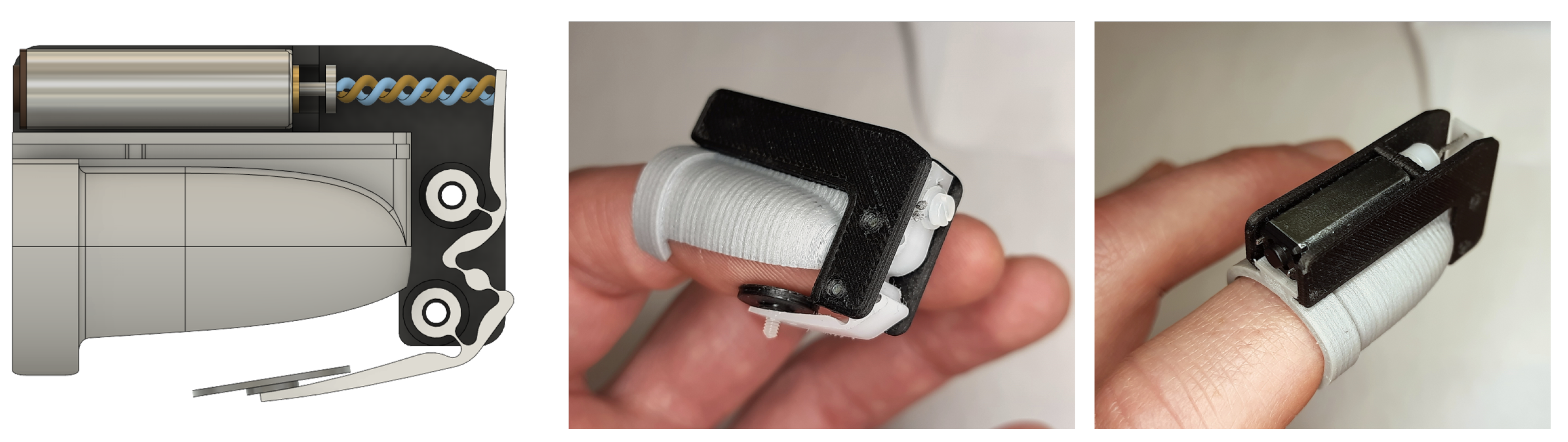
Scheme and developed prototype of the proposed actuation method implementing a twist string actuator and a flexure hinges inversion mechanism for a fingertip haptic device.
Figure 1.
Scheme and developed prototype of the proposed actuation method implementing a twist string actuator and a flexure hinges inversion mechanism for a fingertip haptic device.

Figure 2.
Simplified transmission kinematics. Flexure hinges are modeled as rotary joints.

Figure 3.
FEM analysis of the flexure hinge mechanism when loaded with finger plate moving in free air at 3 mm moving plate displacement. The thickness of the hinges is 0.1 mm in the shown condition.
Figure 3.
FEM analysis of the flexure hinge mechanism when loaded with finger plate moving in free air at 3 mm moving plate displacement. The thickness of the hinges is 0.1 mm in the shown condition.

Figure 4.
FEM analysis of the flexure hinge mechanism with 1 N input loading force, constrained moving plate, and 0.1 mm thickness of the hinges.
Figure 4.
FEM analysis of the flexure hinge mechanism with 1 N input loading force, constrained moving plate, and 0.1 mm thickness of the hinges.

Figure 5.
FEM modal analysis of the flexure hinge mechanism (0.1 mm hinges thickness).

Figure 6.
Results of the FEM modal analyses conducted by varying thickness of the flexure hinges. (Left): ratio between input (actuator side) and output (moving plate) linear force. (Middle): stiffness computed between input force and output displacement when moving in free air. (Right): modal frequencies of the first three modes of vibration.

Figure 7.
Results of the FEM modal analyses conducted by varying thickness of the flexure hinges, with the output plate moving in free air at 3 mm displacement. For each flexure hinge, the graphs show computed strain, stress, and safety factor respectively.
Figure 7.
Results of the FEM modal analyses conducted by varying thickness of the flexure hinges, with the output plate moving in free air at 3 mm displacement. For each flexure hinge, the graphs show computed strain, stress, and safety factor respectively.

Figure 8.
Results of the FEM modal analyses conducted by varying thickness of the flexure hinges, with the output plate constrained and 1 N loading force. For each flexure hinge, the graphs show computed strain, stress, and safety factor respectively.
Figure 8.
Results of the FEM modal analyses conducted by varying thickness of the flexure hinges, with the output plate constrained and 1 N loading force. For each flexure hinge, the graphs show computed strain, stress, and safety factor respectively.

Figure 9.
CAD of the internal components of the final design, and pictures of the implemented prototype, evidencing the slim design of the main body (black plastic) and the interchangeable soft thimble (light gray polymer).
Figure 9.
CAD of the internal components of the final design, and pictures of the implemented prototype, evidencing the slim design of the main body (black plastic) and the interchangeable soft thimble (light gray polymer).

Figure 10.
Exploded view of the final device implementation: it evidences how the twisted string and flexure hinges approach minimizes complexity and number of parts required.
Figure 10.
Exploded view of the final device implementation: it evidences how the twisted string and flexure hinges approach minimizes complexity and number of parts required.

Figure 11.
(a) Force characterization of the actuator in two conditions: the red solid line represents the averaged characteristic from ten repetitions before starting the stress test. The light red shadow is the standard deviation, the red dotted line represents a linear current-to-force model fit on the measured force sensor data, and the black dotted line represents in comparison the ideal current-to-force model of the motor directly coupled to the output mechanism without reduction. The blue solid line represents the averaged characteristics from ten repetitions after the stress test. The blue shadow and the blue dotted line have the same meaning as the red ones after 10 thousand step repetitions. (b) Output force measured in response to a step voltage reference. (c) Frequency response (output force) obtained with a voltage reference chirp signal.


Table 1.
Settings for the genetic algorithm.
| Population Size | 400 |
| Max. Generations | 1000 |
| Function Tolerance | 1 × 10 |
| Max. Stall Generations | 100 |
| Crossover Function | Scattered |
| Selection Function | Tournament, 4 |
| Mutation Function | Adaptive & Feasible |
| Crossover Fraction | 0.5 |
| Elite Count | 0.25 |
Publisher’s Note: MDPI stays neutral with regard to jurisdictional claims in published maps and institutional affiliations. |
© 2021 by the authors. Licensee MDPI, Basel, Switzerland. This article is an open access article distributed under the terms and conditions of the Creative Commons Attribution (CC BY) license (https://creativecommons.org/licenses/by/4.0/).
Share and Cite
MDPI and ACS Style
Leonardis, D.; Tiseni, L.; Chiaradia, D.; Frisoli, A. A Twisted String, Flexure Hinges Approach for Design of a Wearable Haptic Thimble. Actuators 2021, 10, 211. https://doi.org/10.3390/act10090211
AMA Style
Leonardis D, Tiseni L, Chiaradia D, Frisoli A. A Twisted String, Flexure Hinges Approach for Design of a Wearable Haptic Thimble. Actuators. 2021; 10(9):211. https://doi.org/10.3390/act10090211
Chicago/Turabian StyleLeonardis, Daniele, Luca Tiseni, Domenico Chiaradia, and Antonio Frisoli. 2021. "A Twisted String, Flexure Hinges Approach for Design of a Wearable Haptic Thimble" Actuators 10, no. 9: 211. https://doi.org/10.3390/act10090211
Note that from the first issue of 2016, this journal uses article numbers instead of page numbers. See further details here.