An Innovative Circular Ring Method for Measuring Young’s Modulus of Thin Flexible Multi-Layered Materials †

Department of Mechanical Engineering, Meijo University, Nagoya 468-8502, Japan
†
Presented at the 18th International Conference on Experimental Mechanics (ICEM18), Brussels, Belgium, 1–5 July 2018.
Proceedings 2018, 2(8), 553; https://doi.org/10.3390/ICEM18-05441
Published: 12 July 2018
(This article belongs to the Proceedings of The 18th International Conference on Experimental Mechanics)
Abstract
:An innovative mechanical testing method (Compressive Circular Ring Method) is provided for measuring Young’s modulus of each layer in a flexible multi-layered material. The method is based on a nonlinear large deformation theory. By just measuring the vertical displacement or the horizontal displacement of the ring, Young’s modulus of each layer can be easily obtained for various thin multi-layered materials. Measurements were carried out on an electrodeposited two-layered wire. The results confirm that the new method is suitable for flexible multi-layered thin wires. In the meantime, the new method can be applied widely to measure Young’s modulus of thin layers formed by PVD, CVD, Coating, Paint, Cladding, Lamination, and others.
1. Introduction
Young’s modulus of multi-layered materials is very important to predict large deformation in both analytical and technological interests. A new testing method (Circular Ring Method) is based on a nonlinear theory. This paper deals with the compressive technique. Exact analytical solutions are obtained in terms of elliptic integrals. In order to assess the applicability of the proposed method, several experiments were carried out using a two-layered material (Cu: an electrodeposited material + SWPA: a spring steel material). As a result, the new method was found to be suitable for flexible multi-layered materials. Besides the Circular Ring Method studied here, the Axial Compression Method [1], the Own-weight Cantilever Method [2,3] for a flexible multi-layered material have already been developed and reported, based on the nonlinear large deformation theory.
2. Fundamental Theory
A typical load-deformation shape is given in Figure 1 for a circular ring (the initial radius: R0, the whole length of the circular ring: 4L = 2πR0) subjected to opposite compressive forces at two points. As an example, Figure 2 shows the cross-section of a two-layered material.
The analysis is carried out for only the 1/4 part (Region AB, arc length L). The horizontal displacement is denoted by x, the vertical displacement by y, and θ is the deflection angle. Furthermore, the arc length is denoted by s, the radius of curvature by R and the bending moment by M. The relationship among R, M, s, x, y and θ are given by:
where Ei Ii = the flexural rigidity of each layer.
The bending moment applied at an arbitrary position Q(x, y) is expressed as
Introducing the following non-dimensional variables,
Considering the boundary condition, at the point A, the basic equation is derived from Equations (1)–(3) in the form of:
This nonlinear differential Equation (4) is the basic equation that determines large deformation behaviors of a compressive ring.
2.1. In the Case with No Inflection Point [See Figure 1A]
2.1.1. Coverage of the Variable k in Equation (5)
Considering the boundary conditions , and , the maximum non-dimensional arc length ζAB, the maximum non-dimensional vertical displacement ηAB and the maximum non-dimensional horizontal displacement ξAB are obtained as follows.
Similarly, the non-dimensional load γ is
where .
2.1.2. Coverage of the Variable k in Equation (5)
By transforming the variables the maximum non-dimensional arc length ζAB, the maximum non-dimensional vertical displacement ηAB and the maximum non-dimensional horizontal displacement ξAB are obtained as follows.
where .
Similarly, the non-dimensional load γ is
2.2. In the Case with Inflection Point [See Figure 1B]
In this case, a measuring theory can be derived under the coverage of the variable k, . Details of the analytical theory will be omitted here.
Equations (6)–(13) are fundamental formulas to obtain Young’s modulus of each layer, based on the nonlinear large deformation theory. The functions F(k,ϕ), E(k,ϕ) appeared in Equations (6)–(13) are Legendre-Jacobi’s elliptic integrals of the first and second kinds, respectively.
The following formula based on Equation (3) is useful in calculating each Young’s modulus Ei.
where Ii is the second moment of area.
When calculating Young’s modulus Ei using Equation (14), it is not necessary to determine the neutral axis for multi-layered rods/wires because the cross section is symmetrical at any time with respect to the neutral axis. The second moment of area Ii of each cross section for multi-layered rods/wires (diameter di) with respect to the neutral axis is shown as
On the other hand, in case of multi-layered plates it is necessary to determine the neutral axis of materials. The second moment of area Ii of each cross section (thickness hi, width b: common to all) with respect to the neutral axis is shown as
The distance to the neutral axis (see Figure 2a) is obtained as follows.
The first moment of area (Si)z of each cross section (Ai: the cross-sectional area) with respect to z axis is expressed as
One quantity γ (: the non-dimensional load) is required to calculate Young’s modulus Ei from Equation (14). The value of γ is obtained from a chart (: Nomograph) of γ-δ relation (δ the vertical displacement) [Method 1] or γ-λ relation (λ: the horizontal displacement) [Method 2].
3. Techniques of New Measuring Method (Compressive Circular Ring Method)
In this paper, two methods are introduced in order to measure Young’s modulus. The γ-δ and γ-λ relations are presented in Figure 3 and Figure 4, respectively. These charts are computed previously by using Equations (9)–(13). Here, the usage of the chart is recommend by the author. As a point to note, for example, a two-step procedure should be done in a measuring experiment, when Young’s modulus of each layer in a two-layered material is all unknown (Note that a multi-layered material with number of layers n requires a n-step procedure). In other words, it is possible to reduce a frequency of step in proportion to the number, if the number of layers with known Young’s modulus is proven.
3.1. Method 1: (Measurement of δ Only)
The usage of this method is shown below in a two-layered material. Each Young’s modulus Ei is obtained for a SWPA thin wire (: first layer) with 1/4 part length: L1 = 125.0 [mm](4L1(500 [mm]): whole length of the ring), diameter: d1 = 0.38 [mm] and a Cu electrodeposited layer (: second layer) with length: L2 (= L1) = 125.0 [mm], thickness: (d2 − d1)/2 = 0.011 [mm] (d2: 0.402 [mm]).
A chart (: Nomograph) is given in Figure 3, illustrating the relationship of γ and δ//L. Using this chart, each Young’s modulus Ei in a multi-layered material can be calculated from the relational expression given in Equation (14).
3.1.1. First Step Procedure (As a Two-Layered Specimen)
Under the condition of P = 39.24 [mN], δ = 64.7 [mm] (i.e., δ/L = 0.5176) is measured for a double layer and then the value of γ is taken from Figure 3 (γ = 2.470). Therefore, using Equation (14), the combined flexural rigidity (I1 = 1.023 × 10⁻¹⁵[m4]: SWPA, I2 = 2.584 × 10⁻¹⁶ [m4]: Cu) is derived as follows
3.1.2. Second Step Procedure (As a Single-Layered Specimen)
Similarly, δ is measured for a single layer after removing a second layer (Cu). In the condition of P = 34.34 [mN] for a SWPA single layer with length: L1 = 125.5 [mm], diameter: d1 = 0.38 [mm], δ = 64.4 [mm] (i.e., δ/L = 0.5148) is measured and γ is taken newly from Figure 3* (γ = 2.51) [*: Drawing is omitted here.]. Therefore, the flexural rigidity (I1 = 1.023 × 10⁻¹⁵ [m4]: SWPA) can be rewritten as follows from Equation (14) follows.
Using the simultaneous Equations (19) and (20), Young’s modulus E1, E2 of each layer is calculated as E1 = 209.3 [GPa] for a SWPA layer and E2 = 129.9 [GPa] for a Cu layer.
3.2. Method 2: (Measurement of λ Only)
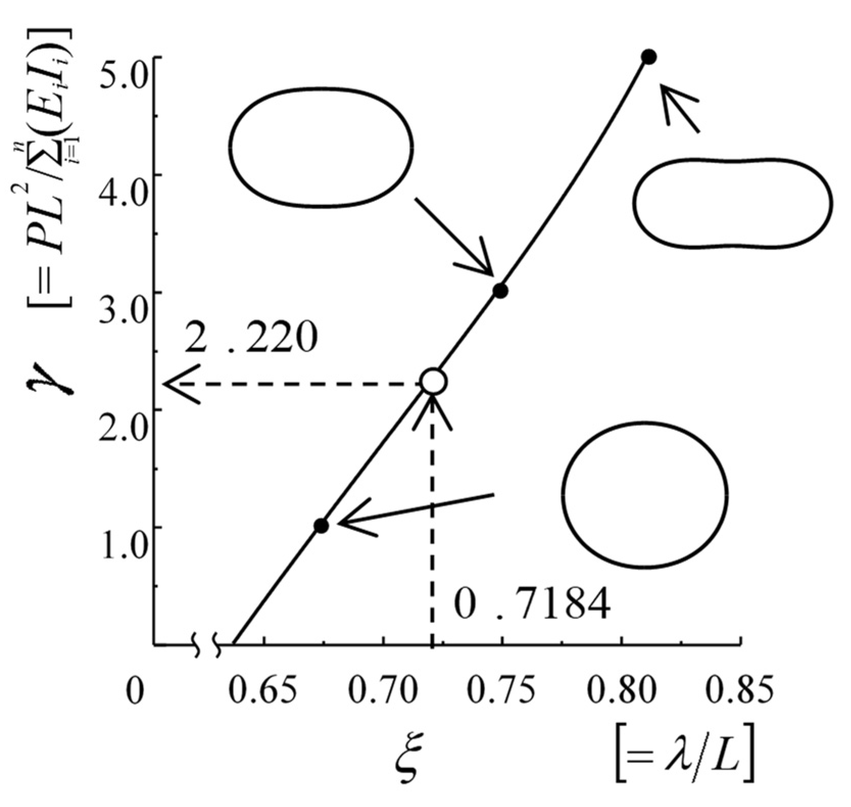
A similar chart (: Nomograph) is given in Figure 4, illustrating the relationship of γ and λ/L. Using this chart, each Young’s modulus Ei in a multi-layered material can be calculated from Equation (14). As an example, Young’s modulus Ei of each layer is obtained for a SWPA thin wire (: first layer) + a Cu thin layer (: second layer) mentioned above (see the tertiary Section 3.1).
3.2.1. First Step Procedure (As a Two-Layered Specimen)
Under the condition of P = 34.34 [mN], λ = 89.5 [mm] (i.e., λ/L = 0.7184) are measured for a double layer and then the value of γ is taken from Figure 4 (γ = 2.220). Therefore, from Equation (14) the combined flexural rigidity (I1 = 1.023 × 10⁻¹⁵ [m4]: SWPA, I2 = 2.584 × 10⁻¹⁶ [m4]: Cu) can be written as follows
3.2.2. Second Step Procedure (As a Single-Layered Specimen)
Similarly, λ is measured for a single layer after removing a second layer (Cu). In the condition of P = 29.43 [mN] for a SWPA single layer, λ = 89.5 [mm] (i.e., λ/L = 0.716) is measured and then γ is taken newly from Figure 4* (γ = 2.15) [*: Drawing is omitted here.]. Therefore, the flexural rigidity (I1 = 1.023 × 10⁻¹⁵ [m4]: SWPA) can be rewritten as follows from Equation (14).
From the simultaneous Equations (21) and (22), Young’s modulus E1, E2 of each layer is calculated as E1 = 209.5 [GPa] for a SWPA layer and E2 = 104.57 [GPa] for a Cu layer.
4. Experimental Investigation
In order to assess the applicability of the Compressive Circular Ring Method, several large deformation experiments were carried out using a two-layered wire [Cu (Copper) layer: an electrodeposited material (0.011 mm thick, 500 mm long) + SWPA layer: a spring steel wire (0.38 mm diameter, 500 mm long)]. The experimental set-up is shown in Figure 5 (which shows a thin multi-layered plate, for example). Since Young’s modulus of each layer in the two-layered material is unknown, the measuring experiments were carried out by adopting the two-step procedure. In every step of the procedures, a vertical displacement δ and a horizontal displacement λ are measured for several compressive loads P by using a grid paper with 1mm spacing.
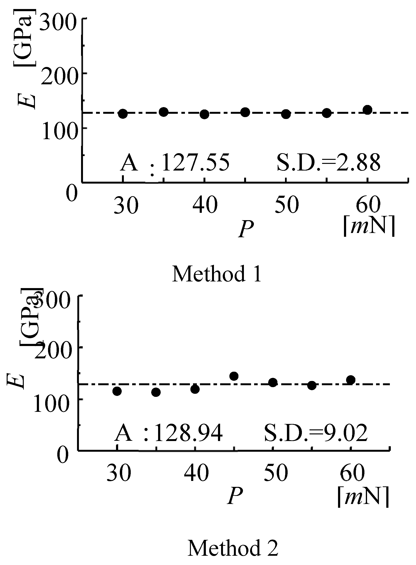
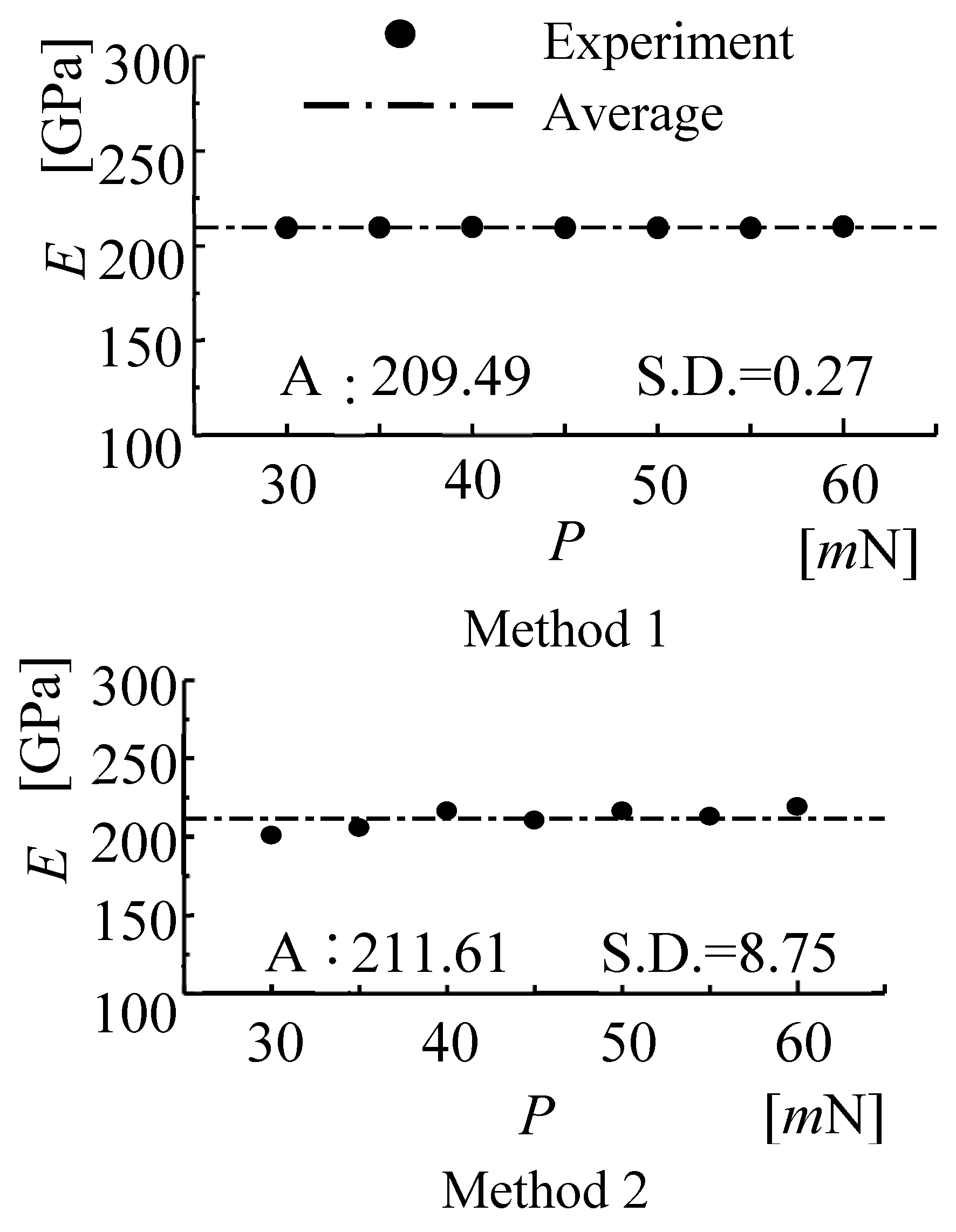
Young’s moduli of Cu and SWPA obtained by applying Method 1 and Method 2 are shown in Figure 6 and Figure 7, respectively. Here, the influence of a load (P) upon Young’s modulus (E) was examined.
The figures were described under a two-layered condition
In a Cu layer (see Figure 6), the measured values of Methods 1 and 2 remain nearly constant for a compressive load and the standard deviation (S.D.) is very small although every method has a little scattered values. As a whole, the mean Young’s moduli (shown as Av.: Average) determined by the two methods are reasonably in good agreement with each other. On the other hand, Trends similar to that of Figure 6 is observed for Young’s moduli of a SWPA layer (see Figure 7). The mean values obtained by the two methods agree well.
5. Conclusions
The “Compressive Circular Ring Method” is proposed as a new and simpler material testing method for measuring Young’s modulus of each layer in a flexible multi-layered material.
From the results of theoretical and experimental analyses, the new method is effective for measuring Young’s modulus of each layer in a flexible multi-layered material. Furthermore, the proposed new method is applicable widely to Young’s modulus measurement in a thin layer formed, for example, by PVD (Physical Vapor Deposition), CVD (Chemical Vapor Deposition), Coating (Graphite, Metal Oxide), Paint (Lacquer), etc.
References
- Ohtsuki, A.; Hayashi, K. An Innovative Method for Measuring Young’s Modulus of Thin Plates and Wires Using Postbuckling Behavior (Compression Column Method). Trans. JSSR 2013, 27–34. [Google Scholar] [CrossRef]
- Ohtsuki, A. An Innovative Mechanical Testing Method for Measuring Young’s Modulus of a Thin Flexible Material (Own-Weight Multi-layered Cantilever Method). In Proceedings of the 34th Danubia Adria Symposium, Trieste, Italy, 19–22 September 2017; pp. 1–2. [Google Scholar]
- Ohtsuki, A. An Innovative Mechanical Testing Method for Measuring Young’s Modulus of a Thin Flexible Materials (Own-Weight Method). In Proceedings of the 21st International Conference on Composite Materials, Xi’an, China, 20–25 August 2017; No.2838. pp. 1–11. [Google Scholar]
Figure 1.
The co-ordinate system for a flexible multi-layered circular ring subjected to opposite compressive forces. (A) In the case with no inflection point; (B) In the case with inflection point a.
Figure 1.
The co-ordinate system for a flexible multi-layered circular ring subjected to opposite compressive forces. (A) In the case with no inflection point; (B) In the case with inflection point a.

Figure 2.
Illustration of cross-section of two-layered material (as an example).

Figure 3.
Non-dimensional chart for the parameter γ when the vertical displacement δ is given.

Figure 4.
Non-dimensional chart for the parameter γ when the horizontal displacement λ is given.

Figure 5.
Experimental set-up (as an example, a multi-layered plate specimen is shown).

Figure 6.
Comparison of Young’s moduli of an electrodeposited material (Cu: E2) between the two measuring methods for various values of the load P. (Note: E1 of SWPA is known previously.).
Figure 6.
Comparison of Young’s moduli of an electrodeposited material (Cu: E2) between the two measuring methods for various values of the load P. (Note: E1 of SWPA is known previously.).

Figure 7.
Comparison of Young’s moduli of a spring steel wire (SWPA: E1) between the two measuring methods for various values of the load P. (Note: E2 of Cu is known previously.).
Figure 7.
Comparison of Young’s moduli of a spring steel wire (SWPA: E1) between the two measuring methods for various values of the load P. (Note: E2 of Cu is known previously.).

Publisher’s Note: MDPI stays neutral with regard to jurisdictional claims in published maps and institutional affiliations. |
© 2018 by the author. Licensee MDPI, Basel, Switzerland. This article is an open access article distributed under the terms and conditions of the Creative Commons Attribution (CC BY) license (https://creativecommons.org/licenses/by/4.0/).
Share and Cite
MDPI and ACS Style
Ohtsuki, A. An Innovative Circular Ring Method for Measuring Young’s Modulus of Thin Flexible Multi-Layered Materials. Proceedings 2018, 2, 553. https://doi.org/10.3390/ICEM18-05441
AMA Style
Ohtsuki A. An Innovative Circular Ring Method for Measuring Young’s Modulus of Thin Flexible Multi-Layered Materials. Proceedings. 2018; 2(8):553. https://doi.org/10.3390/ICEM18-05441
Chicago/Turabian StyleOhtsuki, Atsumi. 2018. "An Innovative Circular Ring Method for Measuring Young’s Modulus of Thin Flexible Multi-Layered Materials" Proceedings 2, no. 8: 553. https://doi.org/10.3390/ICEM18-05441