Influence of the aerodynamic flow on the dynamic characteristics of a lightning sweeping arc
 Cien Xiao
  Yakun Liu*
- Key Laboratory of Control of Power Transmission and Conversion, Ministry of Education, Department of Electrical Engineering, Shanghai Jiao Tong University, Shanghai, China
Lightning arc attachments during swept strokes are key information in the lightning protection design of fast-moving aircraft, wind turbines, rockets, etc. However, numerical modeling has not achieved success to predict the movement of lightning sweeping arcs due to the limited understanding of the complex multi-physics convolution in the arc fluid at present. This work builds a dynamic magneto-hydrodynamic (MHD) arc model based on the setup in the laboratory simulation of the lightning continuing current and couples the electric–magnetic–thermal–force processes to get insights into the lightning arc dynamics. The MHD theory and Newton’s second law of motion are also incorporated to describe the movement of arc segments in the conditions of aerodynamic flows with different intensities. Results show that, at the center region of the arc, the electromagnetic force, thermal buoyancy, and aerodynamic force are competitive, and all are determiners in predicting the arc displacement. In contrast, at the root region of the arc, the electromagnetic force dominates the arc movement with a flow speed under 10 m/s, while aerodynamic force takes the dominant role when the flow speed exceeds 50 m/s. The arc sweeping distance expands from 0.02 to 1.01 m as the aerodynamic flow increases from 5 to 200 m/s. Meanwhile, when increasing the pitch angle of the arc-connected surface, the arc root becomes more attached to the surface and the sweeping distance is predicted to get reduced. The conclusions offer references to construct a numerical model and predict the complex arc movement during lightning sweeping strokes.
1 Introduction
High-speed moving objects, such as aircraft and blades of wind turbines, are known to have a competitive velocity to the migration speed of positive ions (e.g., 1.3 × 10⁻⁴ m/μs at E = 10 kV/cm) in lightning discharge. This triggers the unavoidable lightning sweeping phenomenon on the arc-connected surface, namely, the so-called swept stroke. The lightning arc channel will sweep from one attachment point to another reattachment point and bring damage to different regions, not fixed to the initial arc attachment (Brick et al., 1970; Bublievskii, 1978). These damages can lead to potential hazards to high-speed moving objects, especially to aircraft. To date, it is unfeasible to study the sweeping arcs through the experiments with a representable situation (Plumer, 2012; Andraud, 2022; Sousa Martins et al., 2022). Thus, a numerical model is desired to offer a prediction tool for the arc movements on the connected surface (Lago et al., 2006; Lago et al., 2004; Chemartin et al., 2008; Fisher et al., 2015).
Lightning sweeping arcs feature as a kind of magneto-hydrodynamic (MHD) fluid and also with convoluted electric–magnetic–thermal–force processes. In analyzing the static arcs, the MHD theory is known to deal with the gross plasma fluid behavior of mixed particles (i.e., ions, electrons, and atoms). The gross plasma fluid behavior is quantitatively determined by the electromagnetic forces and viscous force on the plasma flow, in which the electromagnetic forces change with the conductivity of the plasma channel and the associated magnetic field. Typical applications can be found in low-voltage switching devices, plasma torches with rotating arcs, electric arc welding, lightning direct effect test, etc. (Tanaka et al., 2010; Baeva and Uhrlandt, 2011; Abdelal and Murphy, 2017; Gueye et al., 2019). In dynamic lightning sweeping arcs, the MHD theory needs to couple with the aerodynamic force induced by the aerodynamic flow, which is calculated based on the position where the plasma arc segment is situated and also the relative angle of attack. The position of arcs will change in the dynamic sweeping process, and this will fail the traditional resolution in the fixed co-ordinates. Thus, the key in a numerical model of the dynamic lightning sweeping arc is how to disentangle the highly non-convergent procedures with multi-physical interactions and resolve the combined governing equations of Maxwell’s equations of electromagnetism, the Navier–Stokes equations of fluid, the heat transfer equations, and the aerodynamic force equations in the MHD frame (Larsson et al., 2005; Larsson et al., 2000b; Larsson et al., 2000a; Abdelal and Murphy, 2017).
Meanwhile, although we still cannot use experiments to represent the lightning sweeping arcs with a satisfactory length of several kilometers, experimental research studies on lightning arcs still provide us with macroscopic characteristics, such as arc expansion radius and normalized length, by measuring optical signals and electromagnetic signature during discharging (Tanaka et al., 2003; Zaepffel et al., 2016; Cui et al., 2017). The arc expansion radius is defined as the maximum distance of the arc location to the central axis of the electrode system in the experiment. The normalized length of the arc column is defined as the ratio of the effective channel length to gap length. Tanaka et al. used the high-speed imaging technique with a reconstruction algorithm (Tanaka et al., 2001) and found that these two time-dependent parameters manifest a noteworthy pattern with a certain boundary after arc ignition. The mean expansion radius enlarges from 0.11 m to 0.28 m, and the normalized length ranged between 1.5 and 2 when the arc current increases from 100 A to 2000 A (Tanaka et al., 2003). In contrast, other arc parameters such as current density and force are impractical to measure. This drives researchers to dig out the information through numerical modeling. To model the dynamic behavior of the long arc column, Zaglauer et al. put forward a guided numerical frame in 1999 but did not specify how to implement it (Zaglauer et al., 1999). Novak et al. modeled the arc as a conductive rod and set the arc motion speed based on the empirical data. The Cassie formula is adopted to calculate the radius of the arc (Novak and Fuchs, 1974). With the fast development of the computational fluid dynamics (CFD) solver, models combined with the cathode, arc, and anode in the air were established to quantify the temperature and velocity of plasma by Lago et al. (2004) and Chemartin et al. (2011). Tholin et al. further discussed the evolution of a swept lightning arc on the skin of aircraft (Tholin et al., 2014). To date, the influence of aerodynamic flow on dynamic characteristics of lightning sweeping arcs has not made its way into the literature. Also, there are barely any discussions about how the forces (e.g., the thermal buoyancy, aerodynamic force, and magnetic force) are competing in the lightning sweeping arc.
Therefore, this work builds a numerical model to simulate the thermodynamic evolution of a simulated lightning channel during its long continuous current (the so-called LCC) stage. The combined governing equations, representing the multi-physical interactions in the MHD frame, are first translated into partial differential equations and then solved using the finite element method. The dynamic fluid characteristics of sweeping arcs are simulated by the incorporation of Maxwell’s equations, the Navier–Stokes equations, the thermal conductivity heat transfer equations, the aerodynamic force equations, and Newton’s second law. The influence of aerodynamic flow on arc dynamics is addressed through the proposed model. At last, we analyze the competing force in the sweeping arcs and its contribution to the sweeping distance for every separate force. The conclusions of this work can offer insights into the complex arc sweeping phenomenon and the design of lightning protection for aircraft.
2 Numerical implementation of the dynamic arc in the MHD domain
2.1 Coupling equations of the dynamic arc
The lightning sweeping arc is the successor of a leader discharge when an aircraft is struck by lightning, of which the stepped leader and bi-directional leader first create the conductive channels in virgin air. The theoretical analysis of the leader discharge and arc discharge is significantly distinct, which can be understood from the temperature difference between electrons and heavy particles. For propagating the stepped leader or bi-directional leader discharge, the high intensity of the electric field is an important ingredient, and this drives the temperature difference. However, in the arc discharge stage, the electric field has decreased to a very low level, and the elastic collision processes quickly equilibrate the plasma phases to a similar level of temperature in a few microseconds. In lightning arc discharges, the local thermodynamic equilibrium (LTE) conditions can represent the similar level of temperature of electrons and heavy particles. The Boltzmann and Saha equations, derived from spectroscopic diagnostics, can describe the temperature and electron density in the plasma. Meanwhile, the arc plasma can be treated as a Newtonian fluid including the electromagnetic effects. Therefore, we use the MHD frame in the LTE conditions to numerically model the sweeping arcs, whose physical properties and chemical composition of the arc are mainly determined by the temperature and pressure of the plasma (D’Angola et al., 2008).
In the MHD frame, a set of coupled non-linear equations describe the dynamics of the plasma and determine the plasma characteristics in quantity. The background electric field in the dynamic arc regions (including the adjacent air regions) first needs to be explained before coupling these non-linear equations. Then, the mass continuity equation, the momentum conservation equation, the energy conservation equation, and Maxwell’s equations are paired and set as the rules of multiple physics in the calculation (Lowke and Tanaka, 2006).
where
Arc columns are displaced and deformed by the competition effects of the electrodynamic and aerodynamic forces, of which the core arc regions are assumed to be impermeable and can be treated as a solid cylindrical body (Bublievskii, 1978). Therefore, an arc chain model is introduced to perform the static force analysis of the lightning arc (Horinouchi et al., 1997). The lightning arc is assumed to be a chain of unit cylindrical current elements, as shown in Figure 1A, where Gi denotes the center of gravity. Rai and lai are the radius and length of the ith current element, respectively. The direction of the ith current element is defined by the current vector Iai. The simulations are performed in the ground frame of the reference. The direction of the aerodynamic flow is defined as the positive direction of the x-axis. The arc-connected surface is defined as the x–y plane.
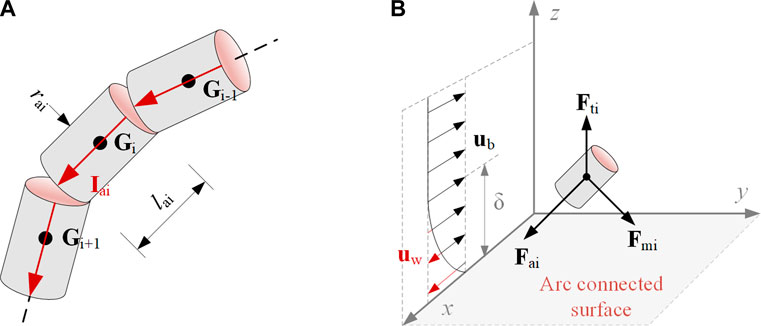
FIGURE 1. Arc chain model and force analysis of the current element, where (A) refers to discreted elements of arc column and (B) represents the spatial force of the ith element.
As shown in Figure 1B, the force working on every element is determined by the electromagnetic force Fmi (or the Laplace force), the thermal buoyancy Fti, and the aerodynamic force Fai. Fmi applies to the arc segment, and its direction is identified by the right-hand rule. The intensity of Fmi will change linearly with the length of the arc segment and the amplitude of the arc current, which can be calculated by Eq. 9. Fti is caused by the temperature difference between the ambient cold air and the arc-affected hot air. The force increases with the volume of the hot air and the density difference with the ambient cold air. The volume of the hot air can be estimated by FEM modeling of the arc segment. We can estimate Fti by multiplying the volume and the difference in density by Eq. 10. Fai is the force exerted on the arc body from the air blowing, in which the force changes with the relative velocity and the area of the arc body facing the air blowing. To calculate the force, Eq. 11 can be adopted.
where Bi is the magnetic induction density of the ith current density, which is defined by the Maxwell equations and the Biot–Savart law (Davidson, 2016). ρ0 and ρ are the mass density of the air at ambient temperature and at the thermal ionized temperature, respectively (Capitelli et al., 2000). Rti is the radius of the air column where temperature increases due to the existence of the arc. G is the gravitational acceleration; Cr is the drag coefficient, which is a function of the Reynolds number (Peelo, 2004). Δui is the velocity difference caused by the aerodynamic flow and can be expressed as
According to Newton’s second law, the velocity of the ith current element can be calculated by Eq. 12.
Therefore, the location of the i+1st current element can be deduced from the location and the movement of the ith current element at each time step.
2.2 Numerical implementation
The direct effects of the lightning arcs are evaluated in the laboratory using a test set-up advised in the SAE ARP5416 document (SAE ARP5416, 2005). The arc is generated between an electrode and an object under the test, e.g., a sample of fuselage or wing material (skin) or an assembly. Thus, in this work, the sweeping arc is simulated in a cathode–arc–anode domain 1 m in width and 0.605 m in height, as shown in Figure 2. The anode is set as the x–y plane, and the cathode is fixed at points (0, 0, and 0.6). The boundary ‘BC’ is set as the bottom side of the cathode with a radius of 5 mm, and the domain ‘EFGH’ is set as the planar anode with a thickness of 5 mm. To acquire the initial conditions of the arc at t = 0, we build a 2D still arc model using COMSOL and extract the parameters (such as temperature and current density.) of the arc. Then, these parameters are translated into Cartesian co-ordinates in a 3D domain so that the dynamic movement of arc segments can be coupled to be calculated in all directions by the drive of competing forces from thermal buoyancy, electrodynamic, and aerodynamic forces.
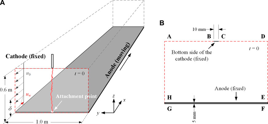
FIGURE 2. Calculation domain (not to scale) of: (A) dynamic arc model, and (B) static arc model.
To describe the ionization of the air and formation of the arc channel, the plasma domain is assigned with the temperature-dependent transport properties of the air plasma calculated by Capitelli et al. (2000). It should be mentioned that the extremely low electrical conductivity of the air (10–14 S/m) at room temperature could lead to numerical divergence. To resolve this problem, we have calculated the electrical conductivity of the air based on its changes with temperature, which is developed to couple the electron transport and electric current governing equations (Abdelal and Murphy, 2017). The model indicates that the electric field quickly increases to 45,000 Townsend at 0.5 μs at the cathode surface, which triggers the electron cold-field emissions and ionization and hence increases the electrical conductivity of the air plasma.
The dynamic arc model (Figure 2A) is implemented using MATLAB to study the competing forces of the arc columns, while the static arc model (Figure 2B) is defined using COMSOL to quantify the electrical and thermal parameters of the arc columns. In this case, the initial condition of the arc channel in the dynamic arc model is defined as a straight line along the z-axis. As for the initial condition of the static arc model, all computational domains are initially at room temperature. The boundary conditions are summarized in Table 1, where ‘RA’ denotes the surface radiation, ‘OB’ denotes open boundary condition, u is the velocity, T is the temperature, J is the current density, V is the electric potential, and A is the magnetic potential. A constant and uniform current density, Jin, is converted from a constant current of 400 A and applied at the bottom side of the cathode ‘BC’. To maintain the current constant, a Dirichlet boundary condition on the electric potential V is applied at the top boundary.
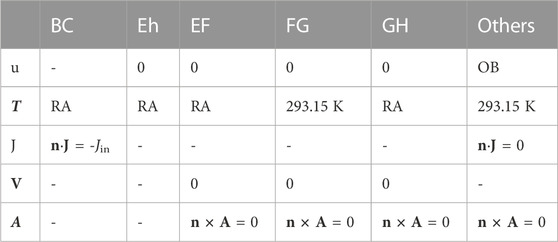
TABLE 1. Boundary conditions of the static arc model.
2.3 Parameters of the numerical model
2.3.1 Current density and temperature profile of the lightning LCC arc
Based on the MHD theory, a fully coupled time-dependent model is built using COMSOL Multiphysics. The computational domain is composed of an arc region and an arc-connected region (or named “anode” region). The material of the 2024 Al alloy is set as the anode with a sample size of 1,000 × 10 mm (width × thickness). It is commonly used in aircraft and used as the material of the arc-connected surface. The LTE transport coefficients applied in this research are calculated by Capitelli et al using the Chapman–Enskog approximation, with the temperature range of 50–100000 K (Capitelli et al., 2000), which can fully cover the temperature profile of the sweeping arc. Typical numerical results of the arc current density and its temperature profile at 100 ms are illustrated in Figure 3. As shown in Figure 3, the lightning arc has an amplitude of 400 A, the typical current intensity in the lightning LCC stage. The maximum current density occurs near the anode due to accumulation of charged particles on the anode surface, as shown in Figure 3A. The highest temperature of the arc can be up to ∼104 K, as shown in Figure 3B.
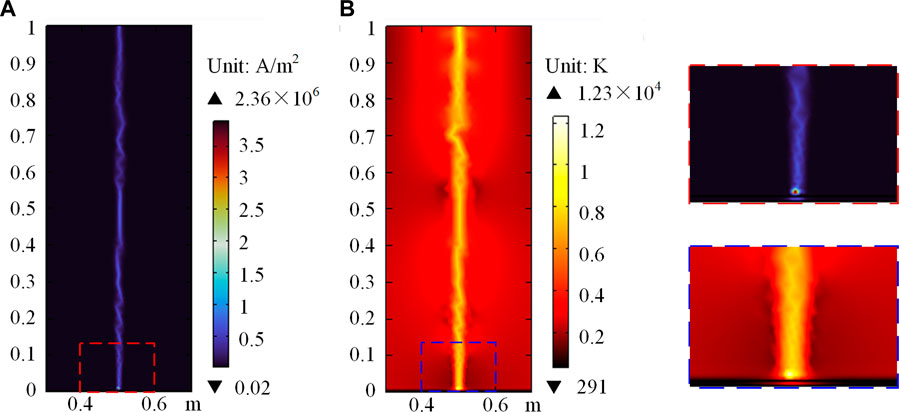
FIGURE 3. Calculation results at 100 ms after arc ignition: (A) current density and (B) temperature.
2.3.2 Radius of the arc segment
Lightning current flows in a narrow cylindrical plasma channel whose radius depends on the current waveform, pressure, density, etc. Based on the so-called ‘strong-shock’ approximation, models describing the dependence of the arc channel radius on the impulse current were first presented in the form of Eq. 14 by Braginskii (1958) and improved by Cooray and Rahman (2005). To describe the continuous expansion of the lightning channel during the decaying part of Component A, Wang and Zhupanska (2015) suggested using the peak current Ipeak instead of the instant current I(t).
where r(t) is the channel radius (in meters) that expands in time; α is the constant, α = 0.294; ρ0 is the air density at atmospheric pressure, ρ0 = 1.29 kg/m3. I(t) is the instant current in amperes (the impulse current is in the double exponential form).
However, the aforementioned conclusion is not applicable to the lightning LCC arc at the arc–anode interface (Tanaka et al., 2003). The observations with high-speed video and numerical simulations show that the profile of the current density and temperature of the lightning LCC arc channel exhibits a Gaussian-like shape at the arc–anode interface. The position of the arc channel is identified as the position with the maximum temperature. Temperature difference between the arc column and ambient air results in mass density variation and thus increases the thermal buoyancy. Therefore, it is possible to evaluate the radius rai by 99% of the total current flows and evaluate the radius rti by the temperature profile, as shown in Figure 4.
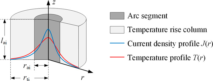
FIGURE 4. Zoning in the ionized air region.
The profiles of current density and temperature on the upper surface of the anode are summarized in Figure 5. Figure 5B indicates a phenomenon that the part of the temperature profile increases with radial position, caused by the energy balance process in the arc jet. The arc jet is considered a magnetic fluid. Since the current density rapidly increases inside the arc (up to 106 A/m2) as shown in Figure 5A, the temperature quickly increases and reaches 10,000 K after a few microseconds. At the same time, the induced Laplace force gives rise to a magnetic pressure with a parabolic shape. This overpressure plays an important role in the dynamics of the arc and in the velocity of the shock wave generated by the arc jet. This overpressure also leads to a significant increase in the radiative emission, which limits the temperature and pressure increase in the core of the arc. On the other hand, the strong energy absorption occurring at the same time in the peripheral regions heats the boundary of the arc, causing the plasma to become conductive, and then current flows in this region. Research carried out by Chemartin et al., 2012 has reached similar conclusions. Moreover, it is noted that, the thermal losses due to the convective cooling of the channel caused by a transverse airflow and its relationship with the arc radius are still a controversial topic (Larsson et al., 2000a; Jayakumar et al., 2006; Cong et al., 2015b). Further attention needs to be paid to the influence of the flow on the radius. Thus, the numerical simulations show an equivalent radius of 11.61 mm (rai) and 24.59 mm (rt) for a 400 A lightning LCC arc. The value is consistent with the observation of the long gap static arc by Goda et al. (2000).

FIGURE 5. Profiles on the upper surface of the anode: (A) current density and (B) temperature.
2.3.3 Spatial distribution of the aerodynamic flow
The lightning LCC arc channel faces the high-speed aerodynamic flow with different velocities at different altitudes. To consider these changing velocities of the aerodynamic flow, we model the aerodynamic flow distribution from the Blasius boundary layer to the free aerodynamic flow region based on the Blasius equation, as shown by the Blasius profile in Figure 6 (Larsson et al., 2000a). The length of the Blasius boundary layer is set to 20 mm, and the free aerodynamic flow region ranges over the Blasius boundary layer of 20 mm. The lightning LCC arc channel is subjected to the aerodynamic flow with a velocity uw in the frame of ground. uw can be deduced from the velocity of the aircraft U∞ and the relative speed in the Blasius profile ub, namely, uw = U∞ − ub. It is noted here that the aerodynamic flow uw input for the following sweeping arc calculation changes with the altitudes, which is equal to 0 at locations far away from the anode and is equal to U∞ at the surface. This phenomenon is consistent with the situation of lightning arcs attaching to a fast-moving object (e.g., aircraft).
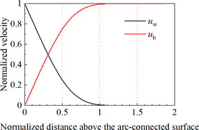
FIGURE 6. Blasius profile representing speeds of a flow ub at the top of a flat plane.
2.4 Solution methodology
After establishing the arc model considering multi-force coupling, the dynamic movement of the arc is calculated using MATLAB. The backward difference method is applied in the form of the Cartesian co-ordinates in space to solve the partial differential equations derived from Newton’s second law. The built-in “ode 45” solver of MATLAB is exerted at the iteration of each time step to solve non-stiff differential equations. The simulation flow chart and the invoking functions (details below) are described in Figure 7, where i refers to the identifier of the current element and n is the pre-stored number of the current elements.
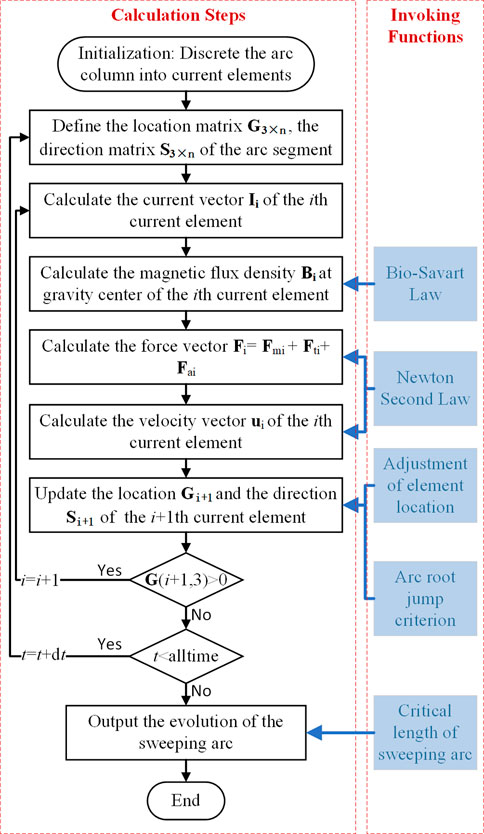
FIGURE 7. Flow chart of the sweeping arc simulation.
For the invoking functions, the following laws or criteria are adopted:
1) The electromagnetic field is deduced from the Biot–Savart Law, a derivation of Maxwell’s equations. The current flows from the fixed cathode to the arc channel and then to the ground through the anode. The cathode is set as a cylinder conductor above the computation domain, with a radius of 10 mm and a length of 100 mm. The Al alloy 2024 is taken as the anode material having isotropic electrical and thermal parameters. The current conductive volume of the anode is also set as a cylindrical region, with the same radius as the arc channel and the length of 5 mm. The magnetic field matrix B is obtained in the solution of the Biot–Savart law by the integration along the complete current conducting path from the cathode (0, 0, and 0.705) to the anode x–y plane at each time step. Since the lightning LCC arc channel can be treated as a long twisted cylindrical body, we obtained the magnetic field matrix B by the integration along the conducting arc column at each time step.
where
2) The locations of the calculation element are adjusted at each time step due to the instability of the arc column. Figure 8 describes two typical situations when the calculation element needs to be adjusted. Figure 8A shows that when the arc column twists within a very close region, the distance between Gi and Gj is considerably small and not able to maintain the insulation of the narrow air gap. Then, Gi and Gj will connect and form a new arc segment; thus, we incorporate this situation in the invoking functions. Figure 8B shows that the continuous arc segments of Gi and Gj dispart with a considerably large distance. For the arc plasma fluid, this situation will form a new arc segment to maintain the current continuity, and this is also incorporated as another invoking function.
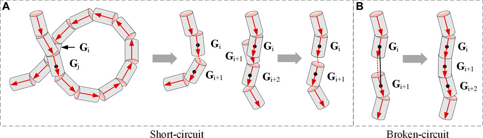
FIGURE 8. Two typical situations with (A) short-circuit and (B) broken-circuit.
3) The arc root jump phenomenon will occur during the stage of lightning LCC arcs. As shown in Figure 9, when the electric field reaches the critical electric field Ebd of the air, a dielectric breakdown may happen in the gap, and this needs to satisfy Eq. 17. The electric field difference between the arc channel and the resistive arc-connected surface triggers the arc root jump. In addition, to maintain the newly formed arc channel, the resistance R2 of the new arc segment must be smaller than the total resistance of the original arc segment and the resistive arc-connected surface. Specifically, the location of the new arc root would satisfy Eqs 18, 19, according to the equivalent distributed circuit analysis.
where Ebd is the critical breakdown electric field of air (about 1–3 kV/mm, changing with temperature), h is the length of the air gap between the arc channel and the resistive surface, R is the resistance, and U is the voltage drop. The subscripts ‘1’, ‘2’, and ‘3’ denote parameters of the original arc segments, the newly formed arc segments, and the surface between two arc roots, respectively. These parameters are time-dependent and affected by the current I, temperature T, and length of arc segment lai.
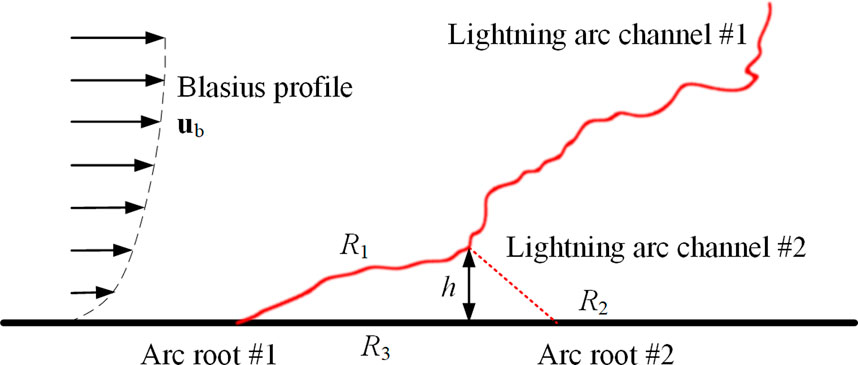
FIGURE 9. Schematic diagram of the arc root jump.
4) In the numerical model of the lightning LCC arc, its length cannot be set arbitrarily, and it must follow the principles of the energy exchange process. Based on the energy exchange process between the arc column and the aerodynamic flow, the heating source of the arc is mainly from the Joule effect, heat conduction, heat convection, and heat radiation. The critical length of the lightning LCC arc set in the numerical model can be deduced from Eq. 20, after which the arc will extinguish, and this terminates the calculation. Thus, the rise in the amplitude of the current would result in a longer critical length and an increased arc extinction time. This phenomenon has already been reported in a research study by Cong et al. (2015b).
where Iam and Uam are the amplitude of the current and voltage of the SI unit, respectively. k is a constant obtained by the fitting curves in the experiment (Cong et al., 2015a).
3 Force competing in the lightning LCC arc
3.1 Different speeds of the aerodynamic flow
The numerical resolution of the dynamic arc model is directly dependent on the diameter of the arc column and the time step. The former can be deduced from the static arc model using COMSOL. The resolution increases with decreasing diameter and time step. It is understandable that a low resolution would result in computational inaccuracy. However, with a high resolution, the distance between Gi and Gi+1 would become so small that the insulation of the narrow air gap can hardly be maintained. In this case, a larger cost of the computing resource is required in the adjustment of the locations of arc elements, resulting in a lower computational efficiency. Thus, we have tried to change the time step of the dynamic arc model from 10–6 to 10–3 s and finally adopted a moderate value in the simulation of 10−5s.
The gap length, that is, the height of the solution domain, is selected as the same value as found in Tanaka et al. (2001), i.e., 0.6 m in modeling and can be adjusted under different conditions. Figure 10A shows the spatial distribution of the lightning LCC arc channel in the current amplitude of 400 A and an airflow speed of 5 m/s in the +x direction. The total electromagnetic force of a certain arc segment is generated by the entire current path, and the resultant force does not have a fixed direction. This means the total electromagnetic force can push the movement of the arc segment in its original direction or opposite direction (not limited to the 180o angle), resulting in the acceleration, slowdown, or spinning of the arc segment. The thermal buoyancy force is sustained under a given arc geometry and always provides a rising force to the arc segment to move upward. The aerodynamic force complies with the relative speed of the aerodynamic flow and will be dictated by the changes in the relative speeds. Figure 10B shows the amplitude of force versus the distance above the arc-connected surface. From Figure 10B, we can find that when the speed of the aerodynamic flow is under 10 m/s, the electromagnetic force predominates among the forces and mainly regulates the arc movement, especially in the regions close to the arc-connected surface. At the center region of the arc column, the electromagnetic force, thermal buoyancy, and aerodynamic force are competitive, and all are determiners in predicting the arc displacement. Meanwhile, the lightning LCC arc elongates by 35% and has a normalized length of 1.35 at 5 ms after its ignition.
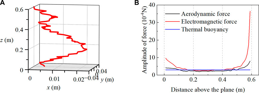
FIGURE 10. Numerical simulation of a 400A lightning LCC arc on the arc-connected surface at 5 ms (u_w=5m/s), with (A) spatial distribution of stationary arc, and (B) force analysis of stationary arc.
When we increase the speed of the aerodynamic flow to 50 m/s, the numerical results and the corresponding force analysis are shown in Figure 11. Results show that the aerodynamic force noticeably increases and exceeds the intensity of the electromagnetic force at the center part of the arc. This implies the lightning LCC arc segments will move following the direction of the aerodynamic flow and sweep on the arc-connected surface. Interestingly, at both ends of the lightning LCC arc, the electromagnetic force still prevails, and this contributes to stabilizing the arc segment hindering its movement in the aerodynamic flowing direction. Also, when the speed of the aerodynamic flow increases, the normalized length of the lightning LCC arc increases to 1.72 at 5 ms after arc ignition, which increases by 27% with an increase of 10 times in the speed of the aerodynamic flow.
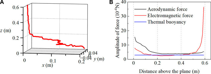
FIGURE 11. Numerical simulation of a 400A lightning LCC arc on the arc-connected surface at 5 ms (u_w=50m/s), with (A) spatial distribution of stationary arc, and (B) force analysis of stationary arc.
Then, we discuss the dynamics of the lightning LCC arc encountering the aerodynamic flows with different speeds of 5–200 m/s. As shown in Figure 12, the lightning LCC arc manifests a significant dynamic response to the changing speeds of the aerodynamic flow. We can see a non-linear increase in the sweeping distance of the arc trajectory on the arc-connected surface from 0.021 m to 1.012 m when the speed of aerodynamic flow intensifies from 5 m/s to 200 m/s. Meanwhile, the expansion radius of the arc decreases by 28.7% (from 0.073 m to 0.052 m). The normalized length of the lightning LCC arc fluctuates between 1.5 and 1.8, and these results are also supported by the findings of Tanaka et al. (2003). For the shape of the lightning LCC arc under different speeds of the aerodynamic flow, the tortuosity of the arc channel clearly increases at strong aerodynamic flowing conditions. This can be understood by the infliction of a stronger aerodynamic flow with a fixed direction at the competing condition with the electromagnetic force in unfixed directions and the thermal buoyancy force in an invariable lifting direction. At the upper end of the arc column, the total resultant force is dominated by the electromagnetic force (see Figure 10B), and arc segments exhibit more straight appearances. In the center part of the arc column, the aerodynamic force predominates the total resultant force (see Figure 10B), and this translates to a more tortuous arc appearance. The more tortuous arc appearance explains the findings of the increased normalized length of the lightning LCC arc with stronger aerodynamic flow.
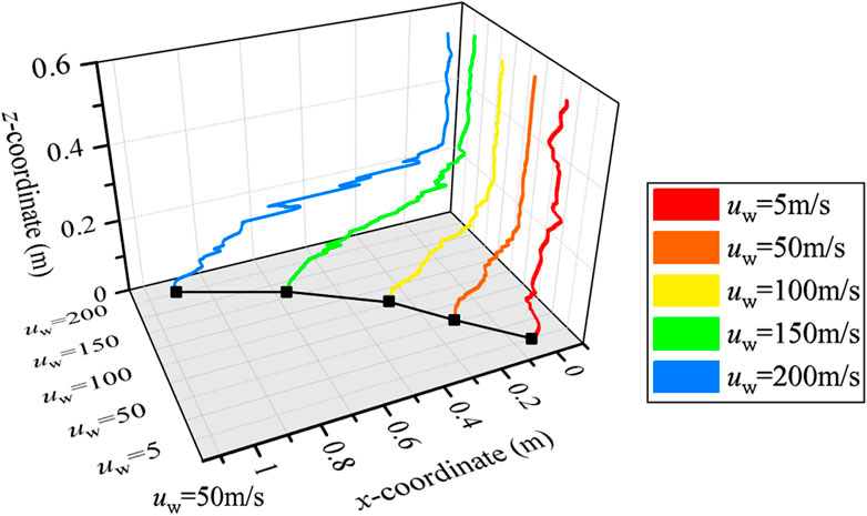
FIGURE 12. Comparison of the sweeping arc at the aerodynamic flow 5–200 m/s.
3.2 Arc deformation on the arc-connected surface with different angles
The lightning LCC arc not only dwells on the connected surface with the 90o angle incidence but can also strike the surface with other angles. For instance, the fast-moving aircraft will tilt its nose up and down by decreasing or increasing lift on the tail. This would give the aircraft an additional pitch, which can be evaluated by the pitch angle ϕ between the longitudinal axis (where the airplane is pointed) and the horizon. Thus, assuming the angle of attack of the fast-moving object is 0, the pitch angles of 15° and 30° are further analyzed to check the arc deformation on the arc-connected surface with different angles. As shown in Figure 13, with the increase in the pitch angles of the arc-connected surface, the lightning LCC arc becomes more tortuous, and the sweeping distance decreases significantly. For instance, the sweeping distances are 0.203, 0.177, and 0.086 m for the pitch angles of 0°, 15°, and 30°, respectively. The decrease can be understood by the intensified electric field and the associated electromagnetic force with the added pitch angles. When the pitch angles of the surface increase, the distance between the arc channel and the arc-connected surface decreases, and this brings an increase in the electric field at a certain voltage. The increased electric field will strengthen the electromagnetic force. As we know the electromagnetic force features force directions perpendicular to the plate of the arc segment, namely, dragging the arc segment to the elevated surface, this will lead the arc root to attach to the surface and decrease the sweeping distance.
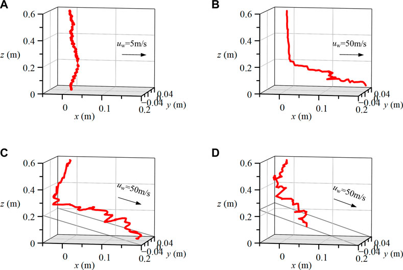
FIGURE 13. Arc deformation on the arc-connected surface with (A) u_w=5m/s, phi=0°, (B) u_w=50m/s, phi=07°, (C) u_w=50m/s, phi=15°, (D) u_w=50m/s, phi=30°.
4 Conclusion
This work builds a dynamic magneto-hydrodynamic arc model and couples the electric–magnetic–thermal–force processes to study the arc dynamics with lightning long continuing current. The magneto-hydrodynamic theory and Newton’s second law of motion are incorporated and describe the movement of arc segments blown by aerodynamic flows with different intensities. Though we still cannot perform the arc sweeping experiments with high-speed moving objects (e.g., aircraft) until now, based on the proposed numerical model, we can get insights into the arc dynamics and learn that
1) The electromagnetic force dominates the arc movement at the arc root region and results in a movement attached to the arc-connected surface. The electromagnetic force, thermal buoyancy, and aerodynamic force are competitive at the center part of the arc and are determiners in predicting the arc displacement. Aerodynamic force takes the dominant role in the arc movement within the Blasius boundary layer when the speed of aerodynamic flow exceeds 50 m/s.
2) The arc sweeping distance of the arc trajectory on the arc-connected surface increases non-linearly with the increasing speed of the aerodynamic flow. When the speed of the aerodynamic flow increases from 5 to 200 m/s, the arc sweeping distance is predicted to increase more than 40 times from 0.021 m to 1.012 m.
3) When the angles of the arc-connected surface increase from 0°, to 15°, and to 30°, the arc root becomes more attached to the surface, and the sweeping distance is predicted to decrease from 0.203 m, to 0.177 m, and to 0.086 m under the aerodynamic flow with the speed of 50 m/s.
Data availability statement
The original contributions presented in the study are included in the article/supplementary materials, further inquiries can be directed to the corresponding author.
Author contributions
CX: developed the model, performed the computations, and wrote the manuscript. YL: conceived the study, designed the analysis, and wrote the manuscript. All authors discussed the results and contributed to the final manuscript.
Funding
The project was funded by the National Natural Science Foundation of China (51977129) and the Natural Science Foundation of Shanghai (21ZR1431400)
Conflict of interest
The authors declare that the research was conducted in the absence of any commercial or financial relationships that could be construed as a potential conflict of interest.
Publisher’s note
All claims expressed in this article are solely those of the authors and do not necessarily represent those of their affiliated organizations, or those of the publisher, the editors, and the reviewers. Any product that may be evaluated in this article, or claim that may be made by its manufacturer, is not guaranteed or endorsed by the publisher.
References
Abdelal, G. F., and Murphy, A. (2017). A multiphysics simulation approach for efficient modeling of lightning strike tests on aircraft structures. IEEE Trans. Plasma Sci. 45, 725–735. doi:10.1109/TPS.2017.2673543
Andraud, V. (2022). Experimental implementation and study of the lightning swept-stroke along an aircraft (phdthesis). Univ. Paris-Saclay.
Baeva, M., and Uhrlandt, D. (2011). Non-equilibrium simulation of the spatial and temporal behavior of a magnetically rotating arc in argon. Plasma Sources Sci. Technol. 20, 035008. doi:10.1088/0963-0252/20/3/035008
Braginskii, S. I. (1958). Theory of the development of a spark channel. Sov. Phys. JETP 34, 1068–1074.
Brick, R. O., Oh, L. L., and Schneider, S. D. (1970). Effects of lightning attachment phenomena on aircraft design. SAE Trans. 79, 2753–2762.
Bublievskii, A. F. (1978). An approximate model of an electric arc in transverse mutually perpendicular aerodynamic and magnetic fields. J. Eng. Phys. 35, 1424–1429. doi:10.1007/BF01104846
Capitelli, M., Colonna, G., Gorse, C., and D’Angola, A. (2000). Transport properties of high temperature air in local thermodynamic equilibrium. Eur. Phys. J. D 11, 279–289. doi:10.1007/s100530070094
Chemartin, L., Lalande, P., Delalondre, C., Cheron, B. G., Andreu, H., and Andre, C. (2008). 3D simulation of electric arc column for lightning aeroplane certification. HighTempMatProc 12, 65–78. doi:10.1615/HighTempMatProc.v12.i1-2.60
Chemartin, L., Lalande, P., Delalondre, C., Cheron, B., and Lago, F. (2011). Modelling and simulation of unsteady dc electric arcs and their interactions with electrodes. Appl. Phys. 13.
Chemartin, L., Lalande, P., Peyrou, B., Chazottes, A., and Elias, P. Q. (2012). Direct effects of lightning on aircraft structure: Analysis of the thermal, electrical and mechanical constraints. AerospaceLab, 1–15.
Cong, H., Li, Q., Xing, J., Li, J., and Chen, Q. (2015a). Critical length criterion and the Arc Chain model for calculating the arcing time of the secondary arc related to AC transmission lines. Plasma Sci. Technol. 17, 475–480. doi:10.1088/1009-0630/17/6/07
Cong, H., Li, Q., Xing, J., and Siew, W. H. (2015b). Modeling study of the secondary arc with stochastic initial positions caused by the primary arc. IEEE Trans. Plasma Sci. 43, 2046–2053. doi:10.1109/TPS.2015.2422777
Cong, H., Wang, S., Zhao, W., Han, D., and Li, Q. (2022). Extinction accelerating device of secondary arc design based on wind load. IEEE Trans. Plasma Sci. 50, 1291–1300. doi:10.1109/TPS.2022.3165161
Cooray, V., and Rahman, M. (2005). “On the relationship between the discharge current, energy dissipation and the NOx production in spark discharges,” in International conference on lightning and static electricity (Seattle USA, 19–23. September, 2005PHE-44.
Cui, Y., Niu, C., Wu, Y., Zhu, M., Yang, F., and Sun, H. (2017). “An investigation of arc root motion by dynamic tracing method,” in 2017 4th International Conference on Electric Power Equipment - Switching Technology (ICEPE-ST), Xian, China, 647–650. doi:10.1109/ICEPE-ST.2017.8188930
D’Angola, A., Colonna, G., Gorse, C., and Capitelli, M. (2008). Thermodynamic and transport properties in equilibrium air plasmas in a wide pressure and temperature range. Eur. Phys. J. D. 46, 129–150. doi:10.1140/epjd/e2007-00305-4
P. A. Davidson (Editor) (2016). “From Maxwell’s equations to magnetohydrodynamics,” Introduction to magnetohydrodynamics, cambridge texts in applied mathematics (Cambridge: Cambridge University Press), 1–120. doi:10.1017/9781316672853.003
Fisher, J., Hoole, P. R. P., Pirapaharan, K., and Hoole, S. R. H. (2015). Applying a 3D dipole model for lightning electrodynamics of low-flying aircraft. IETE J. Res. 61, 91–98. doi:10.1080/03772063.2014.986543
Goda, Y., Iwata, M., Ikeda, K., and Tanaka, S. (2000). Arc voltage characteristics of high current fault arcs in long gaps. IEEE Trans. Power Deliv. 15, 791–795. doi:10.1109/61.853021
Gueye, P., Cressault, Y., Rohani, V., and Fulcheri, L. (2019). MHD modeling of rotating arc under restrike mode in ‘kvaerner-type’ torch: Part I. Dynamics at 1 bar pressure. J. Phys. D. Appl. Phys. 52, 135202. doi:10.1088/1361-6463/aaff3c
Horinouchi, K., Nakayama, Y., Yonezawa, T., and Sasao, H. (1997). A method of simulating magnetically driven arcs. IEEE Power Eng. Rev. 17, 47–48. doi:10.1109/MPER.1997.560686
Jayakumar, V., Rakov, V. A., Miki, M., Uman, M. A., Schnetzer, G. H., and Rambo, K. J. (2006). Estimation of input energy in rocket-triggered lightning. Geophys. Res. Lett. 33, L05702. doi:10.1029/2005GL025141
Lago, F., Gonzalez, J. J., Freton, P., and Gleizes, A. (2004). A numerical modelling of an electric arc and its interaction with the anode: Part I. The two-dimensional model. J. Phys. D. Appl. Phys. 37, 883–897. doi:10.1088/0022-3727/37/6/013
Lago, F., Gonzalez, J. J., Freton, P., Uhlig, F., Lucius, N., and Piau, G. P. (2006). A numerical modelling of an electric arc and its interaction with the anode: Part III. Application to the interaction of a lightning strike and an aircraft in flight. J. Phys. D. Appl. Phys. 39, 2294–2310. doi:10.1088/0022-3727/39/10/045
Larsson, A., Delannoy, A., and Lalande, P. (2005). Voltage drop along a lightning channel during strikes to aircraft. Atmos. Res. Atmos. Electr. 76, 377–385. doi:10.1016/j.atmosres.2004.11.033
Larsson, A., Lalande, P., Bondiou-Clergerie, A., Lalande, P., and Delannoy, A. (2000b). The lightning swept stroke along an aircraft in flight. Part I: Thermodynamic and electric properties of lightning arc channels. J. Phys. D. Appl. Phys. 33, 1866–1875. doi:10.1088/0022-3727/33/15/317
Larsson, A., Lalande, P., Bondiou-Clergerie, A., and Lalande, P. (2000a). The lightning swept stroke along an aircraft in flight. Part II: Numerical simulations of the complete process. J. Phys. D. Appl. Phys. 33, 1876–1883. doi:10.1088/0022-3727/33/15/318
Lowke, J. J., and Tanaka, M. (2006). ‘LTE-diffusion approximation’ for arc calculations. J. Phys. D. Appl. Phys. 39, 3634–3643. doi:10.1088/0022-3727/39/16/017
Novak, J. P., and Fuchs, V. (1974). Dynamic equation and characteristics of a short arc moving in a transverse magnetic field. Proc. Institution Electr. Eng. 121, 81–84. doi:10.1049/piee.1974.0013
Plumer, J. A. (2012). “Laboratory test results and natural lightning strike effects: How well do they compare,” in 2012 International Conference on Lightning Protection (ICLP), Vienna, Austria, 1–17. doi:10.1109/ICLP.2012.6344201
Schlichting, H., and Gersten, K. (2017). Boundary-layer theory. Berlin, Heidelberg: Springer Berlin Heidelberg. doi:10.1007/978-3-662-52919-5
Sousa Martins, R., Andraud, V., Zaepffel, C., and Lalande, P. (2022). “Experimental studies of the sweeping of lightning arcs along an aeronautical material and the arc reattachment phenomenon,” in International conference on lightning and static electricity (ICOLSE) 2022 (Madrid, France.
Tanaka, M., Yamamoto, K., Tashiro, S., Nakata, K., Yamamoto, E., Yamazaki, K., et al. (2010). Time-dependent calculations of molten pool formation and thermal plasma with metal vapour in gas tungsten arc welding. J. Phys. D. Appl. Phys. 43, 434009. doi:10.1088/0022-3727/43/43/434009
Tanaka, S.-I., Sunabe, K.-Y., and Goda, Y. (2003). Internal voltage gradient and behavior of column on long-gap DC free arc. Electr. Eng. Jpn. 144, 8–16. doi:10.1002/eej.10198
Tanaka, S., Sunabe, K., and Goda, Y. (2001). Development of method for estimating long gap free arc column path using image processing technique. IEEJ Trans. Power Energy 121, 481–487. doi:10.1541/ieejpes1990.121.4_481
Tholin, L., Chemartin, P., and Lalande, F. (2014).“Numerical investigation of the surface effects on the dwell time during the sweeping of lightning arcs,” in in 2013 International Conference on Lightning and Static Electricity (ICOLSE 2013), Seattle, United States.
Wang, Y., and Zhupanska, O. I. (2015). Lightning strike thermal damage model for glass fiber reinforced polymer matrix composites and its application to wind turbine blades. Compos. Struct. 132, 1182–1191. doi:10.1016/j.compstruct.2015.07.027
Zaepffel, C., Sousa Martins, R., Chemartin, L., and Lalande, P. (2016). “Study of the interaction of a free burning arc and an aluminium panel,” in 21st international conference on gas discharges and their applications (Japan: NAGOYA).
Keywords: lightning arc, sweeping, MHD, numerical analysis, aerodynamic flow
Citation: Xiao C and Liu Y (2023) Influence of the aerodynamic flow on the dynamic characteristics of a lightning sweeping arc. Front. Astron. Space Sci. 10:1083158. doi: 10.3389/fspas.2023.1083158
Received: 28 October 2022; Accepted: 07 February 2023;
Published: 23 February 2023.
Edited by:
Abhay Srivastava, North Eastern Space Application Centre, IndiaReviewed by:
Sander Nijdam, Eindhoven University of Technology, NetherlandsDirk Uhrlandt, Leibniz Institute for Plasma Research and Technology e.V. (INP), Germany
Shenli Jia, Sichuan University, China
Copyright © 2023 Xiao and Liu. This is an open-access article distributed under the terms of the Creative Commons Attribution License (CC BY). The use, distribution or reproduction in other forums is permitted, provided the original author(s) and the copyright owner(s) are credited and that the original publication in this journal is cited, in accordance with accepted academic practice. No use, distribution or reproduction is permitted which does not comply with these terms.
*Correspondence: Yakun Liu, liuyakunhv@163.com