Battery Earth: using the subsurface at Boulby underground laboratory to investigate energy storage technologies
 Katherine A. Daniels1*†
  Jon F. Harrington1
  Andrew C. Wiseall1
  Edward Shoemark-Banks2
  Edward Hough1 Humphrey C. Wallis1
  Sean M. Paling2
- 1Fluid Processes Research Laboratories, British Geological Survey, Nottingham, United Kingdom
- 2Boulby Underground Laboratory, Science and Technology Facilities Council, Saltburn-by-the-Sea, United Kingdom
Renewable energy provides a low-carbon alternative to power generation in the UK. However, the resultant supply varies on daily, weekly and seasonal cycles, such that for green energies to be fully exploited new grid-scale energy storage systems must be implemented. Two pilot facilities in Germany and the United States have demonstrated the potential of the Earth as a battery to store compressed air, using off-peak surplus energy. Natural accumulations of salt (halite deposits) in the UK represent a large and untapped natural storage reservoir for compressed air with the ability to provide instantaneous green energy to meet peak demand. To realise the potential of this emerging technology, a detailed knowledge of the relationship between mechanics, chemistry and geological properties is required to optimise cavern design, storage potential and economic feasibility. The variable stresses imposed on the rock matrix by gas storage, combined with the cyclic nature of cavern pressurisation are barriers to deployment that need to be addressed to enable large-scale adoption of schemes. Well-designed field experiments are a lynchpin for advancing research in this area, especially when supported by state-of-the-art characterisation and modelling techniques. The research facility at STFC’s Boulby Underground Laboratory presents the ideal location to tackle these fundamental issues to optimise “Battery Earth”.
1 Introduction
Security of energy supply, coupled with a transition towards greater production and use of renewable energy in the United Kingdom and globally, will necessitate an increase in both energy and grid-scale storage. Renewable energy generation (e.g., wind and solar) is susceptible to fluctuations in weather conditions, leading to irregular energy production and uneven supply. Compressed Air Energy Storage (CAES) and Compressed Hydrogen Gas Storage (CHGS) are viable energy technologies that are capable of assisting renewable energy production to be less time- and condition-dependent [1]. CAES systems generate electricity similarly to conventional gas turbines but with the compression (storage) and expansion (generation) operations occurring independently [2]. Conventional diabatic CAES uses a compressor train to compress air (with coolers to reduce air temperature, increase efficiency and reduce thermal stress on the storage cavern), which is injected into the storage cavern. The pressurised air is mixed with natural gas during expansion and operation, and this mixture combusted, before being released and fed through an expander or generator train to generate electricity. The additional fuel is required both to achieve the desired air flow rate through the turbine and ensure there is no low temperature icing risk [2]. In simple terms, CAES systems store compressed air in pore space or voids using excess energy generated (for example, wind energy during periods of low demand such as at night). This and this compressed air is then released as required to drive turbines, producing electricity [3]. Potential storage sites for compressed air include energy bags that are anchored to the sea bed [4] and geological formations; these can be solution-mined salt caverns [1, 5, 6], depleted oil and gas reservoirs [7], aquifers [8] and lined [9, 10] and un-lined [11] rock caverns [12–16]. CHGS follows the same process as CAES, but with the possibility of also using the hydrogen for energy production. For CHGS, hydrogen would be pumped into a storage cavern and could be withdrawn over long periods (e.g., to support static or low-cyclic feedstock applications; these are already commercially operated), or for fast cycling (e.g., to support energy supply; these applications are currently not commercially operated) [17]. Two pilot CAES facilities (Huntorf: E. N. Kraftwerke, Germany; McIntosh: Alabama Electric Corporation, Alabama, United States) have demonstrated this technology’s potential in combination with solution-mined salt caverns [18]; there is a limited amount of commercial-scale hydrogen storage in solution mined caverns [19], but the available salt resource is significantly underutilised for these purposes.
Halite formations are ideally suited to CAES and CHGS facility development because halite is a low permeability, self-healing (visco-plastic) material that can be solution-mined to produce custom-engineered storage caverns. Natural gas storage in the United Kingdom already occurs in salt caverns [20], but the mode of cavern usage will differ dramatically if used for CAES/CHGS. The halite formations in the United Kingdom are both onshore and offshore and were deposited in the Permian and Triassic [13, 16]. Solution-mining of halite to create caverns for CAES/CHGS raises a number of uncertainties including: irregularities in cavern morphology due to differential dissolution rates related to the evaporite’s composition and structure, the impact of stress on cavern geometry and integrity, the presence of insoluble impurities that can affect dissolution and the “growth” of the cavern and build-up at the base of the cavern, and brine disposal produced as a by-product of solution-mining the halite [15]. Additionally, halite can deform plastically at high temperatures and pressures (so-called “creep”) leading to mechanical instability and the collapse of the storage cavern, should the minimum operation pressure not be maintained. Equally, operating the cavern at high gas pressures could result in failure of the rock and leakage of gas. As well as these considerations, the usage of the cavern for CAES/CHGS will necessitate much faster pressure cycling of the cavern than seasonal natural gas storage does, leading to additional uncertainties surrounding creep rates, wall-rock damage and failure. Obtaining an improved understanding of the processes governing formation and operation of storage caverns in halite is therefore of great importance to both the emerging CAES and CHGS technologies and will have notable value on a global level, where extensive salt deposits exist.
2 UK salt deposits
United Kingdom geology provides the resource of two halite groups in the stratigraphic sequence: the Permian (298.9 Ma–251.9 Ma) halites, which are predominantly found in NE England, and the Triassic (251.9 Ma–201.4 Ma) halites, which are predominantly located in the Cheshire region (Figure 1). The Triassic halites are utilised for underground storage of methane gas in Cheshire, and have potential for hosting storage schemes in west Lancashire, Dorset, the East Irish Sea and possibly Somerset. In Cheshire, the Triassic halites are part of the Triassic Mercia Mudstone Group (MMG) and comprise an up to 1,200 m thick deposit of interbedded mudstone with subordinate halite and siltstone units that are part of the Cheshire Basin [13, 21–23]. The Northwich halite is up to 283 m thick, is one of the MMG’s halite members in the Cheshire Basin, and has been studied to understand the control of petrology on dissolution for salt cavern formation [15, 24].
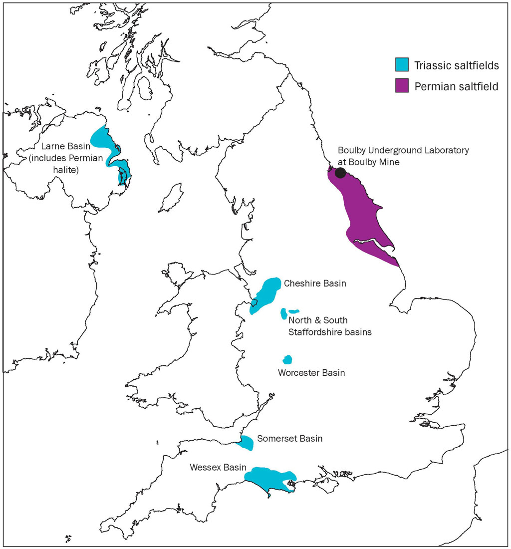
FIGURE 1. The UK's Permian and Triassic Saltfields showing the location of BUL within Boulby Mine (adapted from Evans and Holloway [49], Figure 1 © The Geological Society of London 2009.
The Permian evaporite succession is deeper than the Triassic halites and lies under much of the North Sea; the Zechstein Group sequence containing the Permian halites extends eastwards between the United Kingdom, the Netherlands and Germany [13]. In contrast to Triassic halites, the Zechstein includes beds of higher solubility evaporites including sylvite and carnalite, and also complex polyhalite. This basin’s edge is found at depth under the North Yorkshire coast [13]. These have been mined for potash for fertiliser, and rock salt for road de-icing since the 1960’s [25], and currently mines polyhalite. The Boulby halite is mainly a massive, undeformed halite with an isotropic fabric and crystal grains up to 3 cm in diameter; it is 50 m ± 15 m thick and starts at a depth of 1,100 m [26]. In places it has a gneissose fabric with grains with 3:1 axis ratios, developed in response to structural deformation. In the north of the mine a dark argillaceous halite forms a horizon 5–6 m below the top of the halite [26]. Dolomite, mudstone and anhydrite are interbedded with the Permian salt deposits [13].
3 The Boulby Underground Laboratory
The Science and Technology Facilities Council’s (STFC) Boulby Underground Laboratory (BUL) sits at approximately 1,070–1,100 m below ground surface [27, 28] within Boulby mine, a potash and polyhalite mine operated by Israel Chemicals Limited, in North Yorkshire. BUL, begun in 1988, was motivated by the search for dark matter [27] and hosts experiments requiring low background radiation conditions [28–32]. The background activity from radionuclide contamination (gamma radiation) is particularly low (approximately 0.1 ppm of uranium and thorium and 1,130 ppm of potassium) [27]. Additional mine excavation to increase the laboratory space occurred in 1995, 1998, 2003 [27] and most recently in 2017, when an entirely new laboratory was created. This growth has been advantageous both for the dark matter physics community, but also for scientists wishing to diversify the research undertaken at BUL. As well as housing the United Kingdom Dark Matter Collaboration [30, 33], BUL has a broad appeal as a safe and supported facility for hosting multidisciplinary science. The surface facilities offer visitor office space, computer facilities, a conference suite and storage space for research equipment [27]. The ambient conditions underground are hot and dry; the air temperature is 28°C but rises to 35°C where it is unaffected by mine circulation [34]. The mine roadways are situated in the Boulby Halite and the proximal stratigraphy includes other Permian evaporites. The lithostatic pressure at BUL is 28 MPa and there is no obvious deviatoric stress within the rock mass, other than the decompressed region around the gallery openings.
3.1 Geo-energy research at Boulby Underground Laboratory
BUL offers an unparalleled environment in which to conduct research on geo-energy problems that use our subsurface geology. BUL facilitates the use of representative rocks at depths and temperatures similar to those where some of the deeper gas storage is currently operated, and where new schemes for hydrogen and compressed air could be located to support the UKs net-zero ambitions. At these depths, there can be significant uncertainty in the character of the halite, and this will impact the efficiency of gas storage caverns that could be developed. The infrastructure available in the galleries surrounding the current STFC underground research facility can provide lighting, power, internet, water and waste services, specialist drilling equipment and dedicated science technician support (Figures 2A–C); the value of these services cannot be over-emphasised in what is otherwise a harsh operating mine environment.
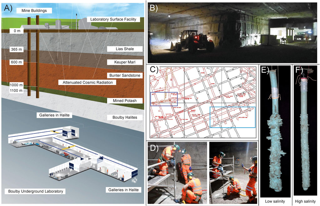
FIGURE 2. The tunnels and galeries around BUL can be used to investigate the dissolution of salt and creation of gas storage caverns. (A) The location of the Boulby Underground Laboratory below ground surface within the stratigrapic succession (modified from the original with permission from STFC, covered under a CC BY-NC-SA 4.0 license). (B) The gallery outside BUL provided the test location. (C) A plan of the galleries near to the shafts (dark blue rectangle), showing the location of the Boulby Underground Laboratory (Dark Matter Area) (light blue rectangle). (D) Scientists from BUL and BGS drill holes into the gallery floor and use both (E) low salinity and (F) high salinity fluids to dissolve elongate caverns during preliminary scoping works, which are then cast and dug out of the ground. The low salinity cast (E) has a length of 77 cm and a volume of 1750 cm3 (measured by laser scanning), whilst the high salinity cast (F) has a length of 76.2 cm and a volume of 906 cm3. The extracted casts have been photographed (E, F) and the surface can subsequently be analysed to provide information on the dissolution process.
With the facilities, expertise and equipment available at the mine, BUL has immense potential to simulate industrial salt-cavern formation through dissolution and the physical processes studied on an intermediate scale (i.e., between single rock sample/laboratory experiment and operational cavern) that is not possible in a standard laboratory (Figures 2B–D). With unique access to a bedded evaporite succession (that includes halite and higher solubility salts carnalite and sylvite, along with non-soluble anhydrite and mudstone), cylindrical caverns with lengths and diameters on the order of 1–3 m could be created at a variety of depths beneath the gallery floor or into the gallery walls (Figures 2B–F). This access would offer the possibility to visualise and quantify halite heterogeneity in three-dimensions in near in-situ conditions for many relevant parameters including lithology, temperature, halite morphology and stress state. A cavity laser scanner, sonic and ground penetrating radar (GPR) would be able provide direct monitoring and measurement during void formation and operation, enabling the study of convergence and creep behaviour related to host rock composition, as well as alterations in the material due to changes in the stress state (associated with opening the cavern volume as well as operating it through pressure cycling). To achieve this, caverns could be sealed with packers, and pressure-cycled over an extended time period, to investigate cyclic loading effects on cavern stability.
A principal area of potential research would be to produce voids at realistic temperatures, depths and lithostatic pressures, using fluids with variable NaCl concentrations and faster flow rates than are possible in the laboratory. If the ground conditions allowed, simulated caverns could be excavated and logged to enable a better understanding of the extent and distribution of heterogeneities and insoluble material in the halite unit, the dependence of cavern shape and volume on mineralogical composition and the consequent impact on aspect ratio. Geophysical data acquisition from the cavern interior (e.g., laser scanning) could be used to create 3D prints for improved visualisation and for use as a public engagement tool. Together, these measurements would lead to an improved understanding of the longevity of gas and CAES storage caverns and the impact of different operational controls on cavern stability and integrity. Experiments would also raise public and stakeholder understanding of cavern storage benefits.
BUL also provides the opportunity to investigate mine heat as a low-carbon energy source. Boulby mine discharges approximately 5 million litres of water daily into the sea. The continued advancement of geothermal technologies means that this presents a considerable potential renewable heat resource that could be exploited. BUL would serve as a research site to optimise either direct air thermal transfer, or heat transfer for mine waters, joining with other subsurface observatories as part of a network investigating the value of mines in supporting net-zero ambitions. To optimise the geological asset that BUL represents, a structured research plan would be required to ensure early research activities do not preclude later activities, avoiding sterilisation of available bedrock through a poorly planned research program. Moreover, as the Boulby halite is within a depth range of 0.75–1.1 km, the stratigraphy is aligned with the anticipated depth of interest for many other renewable, geo-energy and waste disposal problems, including deep geothermal and geological CO2 storage. This ensures BUL’s wide appeal for addressing geo-energy related research problems.
4 Discussion
Increasing the amount of renewable energy used will require large-scale energy storage adoption, as intermittent supply, high initial capital outlay and low power output of conventional renewables also limit their grid-scale deployment. Whilst the United Kingdom is committed to decarbonisation through agreements such as the 2016 Paris accord [20], fossil fuels still comprise a significant proportion of the energy supplied (currently about 78% of all United Kingdom energy in 2022 [35]) and are acknowledged to remain a significant part of the energy mix for decades to come [36]. Whilst coal dependency has declined over the past decade [37], natural gas dependency has risen. The United Kingdom is increasingly dependent on natural gas imports, but has relatively little gas storage capacity compared with many EU member states, rendering it susceptible to the risk of gas supply shortfalls [20].
To achieve the emissions targets set out by the 2019 Net Zero amendment to the Climate Change Act (2008), and to optimise use of hydrogen as a route to achieving these, nascent CAES and CHGS technologies are required to allow transitioning from hydrocarbons to sustainable, clean power generation. Significant attention is now turning towards these technologies with the proposed establishment of two United Kingdom clusters (H21 Leeds City Gate Project [38] and HyNet North West Project [39]), and the Industrial Decarbonisation Research and Innovation Centre (IDRIC) [40]. Rock salt has been successfully used for the storage of natural gas since 1961 [20], but existing facilities offer limited storage capacity compared to the grid-scale requirements for industrial power generation. The United Kingdom has suitable salt formations for geological energy storage in abundance; a substantial and underutilised resource [41]. However, geological energy storage presents many technical and environmental challenges.
The greater Permian evaporite depths mean that although the rocks may provide large capacities for gas storage, the stress conditions for cavern formation are different to those experienced when solution mining in the shallower Triassic deposits, and plastic deformation will be a relevant consideration in some locations. Understanding the role of stress on the dissolution and subsequent cavern shape formed is of fundamental importance to the successful creation and operation of caverns in the Permian halite. Using the currently available compressor technology, the optimal depth for CAES is 300–1,500 m [3]. Compressor technology is continuing to improve; with better compressors, deeper cavern depths can be achieved. Pairing compression and storage facilities with renewable energy sources will enable excess energy to be used to electrically power a turbocompressor to compress air or hydrogen, and this compressed gas can then be stored in close proximity, reducing the need for transport infrastructure and associated costs, and increasing the system efficiency. The North Sea is a favourable location for wind-farms and therefore the Permian evaporite succession is an ideal host rock for salt cavern formation for CAES and CHGS [42], as the improved compressor technology allows deeper formations to be accessed; offshore hydrogen production via sea water hydrolysis is a distinct possibility. In addition, offshore salt cavern formation would reduce both the environmental and societal impact [42].
In contrast to natural gas storage, CHGS and CAES experience rapid withdrawal and refilling cycles with corresponding rapid pressure changes. These result in large cavern wall temperature changes [43, 44], which can substantially reduce the tangential (or vertical) stress, leading to cracking if the material enters the failure regime; this is especially important for bedded salts where the cavern aspect ratios lead to large diameters with respect to cavern height [45]. To maintain cavern integrity, the tangential stresses at the wall must remain compressive during operation. Pressure, temperature and stress therefore emerge as key criteria in the consideration of short- and long-term cavern performance. These issues are strongly influenced by their orientation to the in-situ stress field, and must therefore be given attention when modelling cavern behaviour. Visco-plastic behaviour during pressure cycling often results in substantial reduction in cavern capacity (e.g., Eminence Salt Cavern, Mississippi) [46]. Understanding this behaviour is essential for accurate long-term volume loss predictions and consequently the economic potential through time. A solution to the problem of time-dependent deformation, temperature change, and the resultant stress response, is required to parameterise appropriate experimental scenarios (e.g., isobaric or isochoric storage), and to assess widespread geological energy storage viability. How these are impacted by differing lithologies, as well as lateral and vertical variability, will also need to be understood. These considerations directly control the permissible inter-cavern spacing, affecting infrastructure costs and optimising subsurface halite deposit use. As the storage facility “footprint” increases, it may also span multiple planning regions, complicating the permitting process. As cavern number and size increases, the population affected by CHGS/CAES is likely to increase. For these reasons, there are clear economic, engineering and public acceptance advantages in minimising industry footprint.
The intergenerational climate change challenge is one of the most significant threats facing society, and the United Kingdom government’s pledge to reach net-zero by 2050 will contribute towards meeting it [47]. A shift towards renewable energy for electricity generation, heat and industrial processes will be necessary, requiring long-duration energy storage to ensure supply security [47]. The Carbon Trust [48] estimates that effective United Kingdom energy storage could save as much as £2.4 billion/year by 2030, leading to a significant reduction in the average household energy bill. CAES and CHGS could play an important role in realising this potential through UK-based storage sites, some of which are already planned. The BUL offers a unique environment to enable testing to answer the remaining questions surrounding using Earth as a battery; bringing this to the forefront of discussions is clearly extremely important.
4.1 Permission to reuse and copyright
Figures, tables, and images will be published under a Creative Commons CC-BY licence and permission must be obtained for use of copyrighted material from other sources (including re-published/adapted/modified/partial figures and images from the internet). It is the responsibility of the authors to acquire the licenses, to follow any citation instructions requested by third-party rights holders, and cover any supplementary charges.
Data availability statement
The raw data supporting the conclusion of this article will be made available by the authors, without undue reservation.
Author contributions
KD and JH contributed to conception and design of the study. KD, JH, AW, ES-B, HW, and SP organised preliminary fieldwork campaigns at Boulby Underground Laboratory. KD, JH, and AW analysed an initial dataset. KD wrote the first draft of the manuscript. JH and EH wrote sections of the manuscript. All authors contributed to the article and approved the submitted version.
Funding
Funding for this work was provided by the British Geological Survey and the Science and Technology Facilities Council.
Acknowledgments
The authors thank Dr. Lorraine Field of the British Geological Survey for her helpful review of an earlier version of the manuscript, and Dr. David Evans is thanked for his insightful discussion. Simon Holyoake provided assistance with the instrumentation and experimental apparatus during preliminary field testing and data acquisition, for which the authors are grateful. Wayne Leman is also thanked for his help in the manufacture of field equipment. This paper is published with the permission of the Director of the British Geological Survey, part of United Kingdom Research and Innovation (UKRI).
Conflict of interest
The authors declare that the research was conducted in the absence of any commercial or financial relationships that could be construed as a potential conflict of interest.
Publisher’s note
All claims expressed in this article are solely those of the authors and do not necessarily represent those of their affiliated organizations, or those of the publisher, the editors and the reviewers. Any product that may be evaluated in this article, or claim that may be made by its manufacturer, is not guaranteed or endorsed by the publisher.
References
1. Crotogino F, Donadei S. Grid scale energy storage in salt caverns. In: Proceedings of the 8th Int. Workshop on Large-Scale Integration of Wind Power into Power Systems; October 2009; Bremen, Germany (2009).
3. Luo X, Wang J. Overview of current development on compressed air energy storage. Tech Rep Coventry, United Kingdom: School of Engineering, University of Warwick (2013).
4. Pimm A, Garvey S, De Jong M. Design and testing of Energy Bags for underwater compressed air energy storage. Energy (2014) 66:496–508. doi:10.1016/j.energy.2013.12.010
5. Martinez JD. Role of salt domes in energy productions. In: AH Coogan, editor. Fourth sym - posium on salt. Cleveland: UT NEWS (1974). p. 259–66.
6. Allen RD, Doherty TJ, Thomas RL. Geotechnical factors and guidelines for storage of compressed air in solution mined salt cavities. Tech Rep (1982). doi:10.2172/5234728
7. Donadei S, Schneider GS. Chapter 6: Compressed air energy storage in underground formations. In: Storing energy. Amsterdam, Netherlands: Elsevier (2016). doi:10.1016/B978-0-12-803440-8.00006-3
8. Li Y, Li Y, Liu Y, Cao X. Compressed air energy storage in aquifers: Basic principles, considerable factors, and improvement approaches. Rev Chem Eng (2021) 37:561–84. doi:10.1515/revce-2019-0015
9. Kim HM, Rutqvist J, Ryu DW, Choi BH, Sunwoo C, Song WK. Exploring the concept of compressed air energy storage (CAES) in lined rock caverns at shallow depth: A modeling study of air tightness and energy balance. Appl Energ (2012) 92:653–67. doi:10.1016/j.apenergy.2011.07.013
10. Rutqvist J, Kim HM, Ryu DW, Synn JH, Song WK. Modeling of coupled thermodynamic and geomechanical performance of underground compressed air energy storage in lined rock caverns. Int J Rock Mech Mining Sci (2012) 52:71–81. doi:10.1016/j.ijrmms.2012.02.010
11. Zhou Y, Xia C, Zhao H, Mei S, Zhou S. An iterative method for evaluating air leakage from unlined compressed air energy storage. CAES caverns (2018) 120:434–45. doi:10.1016/j.renene.2017.12.091
12. Allen K. Caes: The underground portion. IEEE Trans Power Apparatus Syst (1985) 104:809–12. doi:10.1109/tpas.1985.319078
13. Cooper AH. Halite karst geohazards (natural and man-made) in the United Kingdom. Environ Geology (2002) 42:505–12. doi:10.1007/s00254-001-0512-9
14. Evans DJ, Chadwick RA. Underground gas storage: An introduction and UK perspective. London: Special Publication The Geological Society of London (2009). p. 1–11. doi:10.1144/SP313.1
15. Field LP, Milodowski AE, Parkes D, Evans DJ. Petrological and textural factors that may influence the dissolution of halite during the construction of salt caverns for the storage of natural gas and compressed air. Tech Rep. British Geological Survey (2013).
16. Evans DJ. Operational ranges of current and proposed underground natural gas storage and CAES facilities. Tech Rep. British Geological Survey (2013) 291pp.
18. Dooner M, Wang J. Chapter 14: Compressed air energy storage. In: Future energy. Netherlands: Sciencedirect (2020).
19. Edlmann K, Dopffel N, Hough E, Xie Q, Groenenberg R, Yallup C, et al. IEA Hydrogen TCP task 042: Underground hydrogen storage (2023).
20. Evans D. An appraisal of Underground Gas Storage technologies and incidents, for the development of risk assessment methodology. Tech Rep. British Geological Survey, Open Report OR/07/023 (2007).
21. Brooks TG, O’Riordan NJ, Bird JF, Stirling R, Billington D. Stabilisation of abandoned salt mines in north west England. London: Geological Society of London (2006).
22. Maddox SJ, Blow R, Hardman M. Hydrocarbon prospectivity of the central Irish sea basin with reference to block 42/12, offshore Ireland. London: Special Publication The Geological Society of London (1995). p. 57–77.
23. Maingarm S, Izatt C, Whittington RJ, Fitches WR. Tectonic evolution of the southern-central Irish sea basin. J Pet Geology (1999) 22:287–304. doi:10.1111/j.1747-5457.1999.tb00988.x
24. Field LP, Milodowski AE, Evans DJ, Palumbo-Roe B, Hall MR, Marriott AL, et al. Determining constraints imposed by salt fabrics on the morphology of solution-mined energy storage cavities, through dissolution experiments using brine and seawater in halite. Q J Eng Geology Hydrogeology (2019) 52:240–54. doi:10.1144/qjegh2018-072
25. Kemp SJ, Smith FW, Wagner D, Mounteney I, Bell CP, Milne CJ, et al. An improved approach to characterize potash-bearing evaporite deposits, evidenced in North Yorkshire, United Kingdom. Econ Geology (2016) 111:719–42. doi:10.2113/econgeo.111.3.719
26. Talbot CJ, Tully CP, Woods PJE. The structural geology of Boulby (potash) mine, Cleveland, United Kingdom. Tectonophysics (1982) 85:167–204. doi:10.1016/0040-1951(82)90102-0
27. Miramonti L. European underground laboratories: An overview. AIP Conf Proc (2005) 785. doi:10.1063/1.2060447
28. De Angelis SH. Earth science at the UK’s deepest laboratory. Géotechnique (2017) 33:132–7. doi:10.1111/gto.12190
29. Bettini A. Underground laboratories. Nucl Instr Methods Phys Res Section A: Acc Spectrometers, Detectors Associated Equipment (2011) 626-627:S64–8. doi:10.1016/j.nima.2010.05.017
30. Murphy A, Paling S. The Boulby mine underground science facility: The search for dark matter, and beyond. Nucl Phys News (2012) 22:19–24. doi:10.1080/10619127.2011.629920
31. Smith NJT. The development of deep underground science facilities. Nucl Phys B (2012) 229-232:333–41. doi:10.1016/j.nuclphysbps.2012.09.052
32. Cockell CS, Biller B, Bryce C, Cousins C, Direito S, Forgan D, et al. The UK Centre for astrobiology: A virtual astrobiology Centre. Accomplishments and lessons learned. Astrobiology (2018) 18:224–43. doi:10.1089/ast.2017.1713
33. Klinger J, Clark SJ, Coleman M, Gluyas JG, Kudryavtsev VA, Lincoln DL, et al. Simulation of muon radiography for monitoring CO2 stored in a geological reservoir. Int J Greenhouse Gas Control (2015) 42:644–54. doi:10.1016/j.ijggc.2015.09.010
34. Ianni A. Considerations on underground laboratories. XV Int Conf Top Astroparticle Underground Phys (2020) 1342:012003. doi:10.1088/1742-6596/1342/1/012003
35. UK Parliament. Accelerating the transition from fossil fuels and securing energy supplies (2023).
36. Petroleum. BP energy outlook 2019 edition (2019). Available at: https://www.bp.com/en/global/corporate/news-and-insights/press-releases/bp-energy-outlook-2019.html (Accessed January 31, 2023).
37. Department for Business Energy Industrial, Strategy. Digest of UK energy statistics annual data for UK (2021). Available at: https://assets.publishing.service.gov.uk/government/uploads/system/uploads/attachment_data/file/1130501/DUKES_2022.pdf (Accessed January 31, 2023).
38. H21 Programme. H21 Leeds city gate project Full Report (2016). https://h21.green/projects/h21-leeds-city-gate/ (Accessed January 31, 2023).
39. Cadent your gas Network. HyNet North West: From vision to reality, project report (2018). Available at: https://hynet.co.uk/app/uploads/2018/05/14368_CADENT_PROJECT_REPORT_AMENDED_v22105.pdf (Accessed January 31, 2023).
40. IDRIC. Industrial decarbonisation research and innovation Centre (2023). Available at: https://idric.org/ (Accessed January 31, 2023).
41. Williams JDO, Williamson JP, Parkes D, Evans DJ, Kirk KL, Nixon S, et al. Is there sufficient storage capacity to support a hydrogen economy? Estimating the salt cavern storage potential of bedded halites in the United Kingdom. J Energ Storage (2022) 53:105109. doi:10.1016/j.est.2022.105109
42. Kepplinger J, Donadei S. Large scale energy storage in geological formations. In: Proceedings of the 6th Dubrovnik Conference on Sustainable Development of Energy, Water and Environment Systems; January 2011; Croatia (2011).
43. Nieland J. Feasibility of off-loading chilled natural gas in salt caverns: Geomechanical assessment. In: Proceedings of the SMRI Spring Conference; October 2004; San Antonio, Texas (2004).
44. Nieland J. Salt cavern thermodynamics - comparison between hydrogen, natural gas and air storage. In: Proceedings of the SMRI Fall Conference; April 2008; Marble Falls, Texas, USA (2008).
45. Diessl J, Wang W, Bruno MS. Investigation of pressure and temperature cycling influence on the stability of bedded salt caverns. Berlin, Germany: Solution Mining Research Institute Fall Conference (2019).
46. Serata S, Cundey T. Design variables in solution cavities for storage of solids, liquids and gases. In: Proceedings of the 5th symposium on salt; October 1979; Adelaide, Australia (1979).
47. The Department for Business E, Strategy I. The energy white paper: Powering our net zero future (2020).
48. Lehmann N, Lever A, Sanders D, Ravishankar M, Ashcroft M. Can storage help reduce the cost of a future UK electricity system? The Carbon Trust (2016). Available at: https://www.carbontrust.com/our-work-and-impact/guides-reports-and-tools/energy-storage-report-can-storage-help-reduce-the-cost.html (Accessed April 19, 2023).
Keywords: energy storage, compressed air, hydrogen and gas storage, in-situ testing, rock salt, cyclic pressurisation, creep, wall rock failure, operational limits
Citation: Daniels KA, Harrington JF, Wiseall AC, Shoemark-Banks E, Hough E, Wallis HC and Paling SM (2023) Battery Earth: using the subsurface at Boulby underground laboratory to investigate energy storage technologies. Front. Phys. 11:1249458. doi: 10.3389/fphy.2023.1249458
Received: 28 June 2023; Accepted: 19 September 2023;
Published: 17 October 2023.
Edited by:
Lorenzo Ferrari, University of Pisa, ItalyReviewed by:
Zhenyuan Yin, Tsinghua University, ChinaCopyright © 2023 Daniels, Harrington, Wiseall, Shoemark-Banks, Hough, Wallis and Paling. This is an open-access article distributed under the terms of the Creative Commons Attribution License (CC BY). The use, distribution or reproduction in other forums is permitted, provided the original author(s) and the copyright owner(s) are credited and that the original publication in this journal is cited, in accordance with accepted academic practice. No use, distribution or reproduction is permitted which does not comply with these terms.
*Correspondence: Katherine A. Daniels, danielsk4@cardiff.ac.uk
†Present address: Katherine A. Daniels, School of Earth and Environmental Sciences, Cardiff University, Cardiff, United Kingdom