Special theory of relativity for a graded index fibre
 Shinichi Saito
- Center for Exploratory Research Laboratory, Research & Development Group, Hitachi, Ltd., Tokyo, Japan
The speed of light (c) in a vacuum is independent of the choice of frames to describe the propagation, according to the theory of relativity. We consider how light is characterised in a material, where the speed of light is different from that in a vacuum due to the finite dielectric constant. The phase velocity in a material is smaller than c, such that the speed of a moving frame can be larger than the phase velocity, such that the frame can move faster than the speed of light in a material. Consequently, an unusual Doppler effect is expected, and the wavelength in the moving frame changes from the red-shift to the blue-shift upon increasing the speed of the frame. The corresponding energy of the light also changes sign from positive to negative, while momentum is always positive, leading to the changes of signs for the phase velocity and the helicity. In a graded index fibre, where the exact solution is available, even more complicated phenomena are expected, due to the finite effective mass of photons. Upon the increase of the energy gap, generated by optical confinements and optical orbital angular momentum, the effective mass of photons increases. If the gap is large enough, momentum starts to change the sign upon increasing the frame velocity, while the energy of photons is always positive. In this case, the phase velocity diverges if momentum is in agreement with the fame velocity. Contrary to the unusual behaviours of the phase velocity, the group velocity is always below c. This thought experiment might be useful for considering insight into the polarisation state of light.
1 Introduction
Einstein created a legacy with the establishment of the theory of relativity [1, 2], which continues to attract a wide range of researchers and engineers more than a century later. The story goes that Einstein considered how light would be seen by an observer travelling as fast as the speed of the light [3], leading to the discovery of the law that the speed of light (c) and the propagation of light in a vacuum is independent of the frame of reference of any observer, as inferred by Maxwell equations [4, 5]. The universal relationship of space and time through the Lorentz transformation led to various non-trivial results, such as Doppler effects of light, time dilation, length contraction, and the energy-momentum relationship of
Nevertheless, inside a material, a speed of a moving frame can exceed the speed of light due to a larger refractive index (n) than one of a vacuum, as experimentally proved by Cherenkov radiation [10–12]. A charged particle with a speed exceeding the phase velocity of light in a material produces a coherent shock wave, similar to the sonic waves made by a supersonic aircraft. Cherenkov radiation is usually observed in water as a bluish conical ray, emitted from a charged elementary particle, which enabled physicists to observe neutrino oscillations [13]. Here, we would like to revisit the original proposition of Einstein: how light is seen in a material by an observer, when travelling at a speed exceeding the phase velocity of light?
Our motivation is to understand the internal quantum structure of a photon, particularly to gain insights to clarify the correlation between spin and polarisation [14–17]. One might think that it is firmly well-established that the spin of photons describes the polarisation of light [4, 5, 18–23], such that the correlation is obvious. However, this is highly non-trivial, as implied by Einstein, confessing that he could not understand what light quanta are at all after 50 years of continuous consideration [3], regardless of the fact that he established a theory for a photoelectric effect as evidence of the particle nature of the photon.
We have a hypothesis that the polarisation of light is a macroscopic manifestation of the spin of a photon as a quantum-mechanical feature. We have shown that a wavefunction of a photon is described by a Helmholtz equation [4, 5, 14], which does not necessarily give a plane-wave form and the solution depends on a profile of the refractive index and a symmetry of system. A ray of photons, emitted from a laser source, is described by a many-body coherent state [14–17, 24–29] with fixed phases, which describe an SU(2) state for the spin state of macroscopically condensed photons. By calculating the quantum-mechanical average of spin operators, we have shown that the expectation values of spin of photons are actually Stokes parameters in Poincaré sphere [14, 30, 31]. The magnitude of spin becomes
The aim of this paper is to understand the photonic state in a material seen by an observer travelling at a speed comparable to or even greater than the speed of light. In a photonic crystal [42] or an optical fibre [5], the dispersion relationship of a photon is precisely engineered to adjust the speed of light and other photonic properties. We consider a uniform material and a GRIN fibre as examples because we can treat the dispersion exactly, in an analytic way.
2 Principle
2.1 Lorentz transformation
We are not challenging the established Lorentz transformation at all [1, 2, 4, 43–47]. The energy scale we are considering is of the order of 1 eV such as for fibre optics, such that the space-time relationship of the vacuum must be robust in the presence of a material. We assume the rest frame of (t, x, y, z), where fibre optic materials are located, and consider how the light will be observed by the moving from of (t′, x′, y′, z′) at the speed of vz along the positive +z direction. The Lorentz transformation, L, whose determinant is unity, det(L) = 1, is defined by.
where a2 − b2 = 1, and parameters a and b are determined by the principle of relativity, guaranteeing that the speed of light in a vacuum is independent of the measurement frame. In order to impose the principle, we start from the Helmholtz equations in a vacuum.
where Ψ(t, x, y, z) and Ψ′(t′, x′, y′, z′) are wavefunctions of a photon for the frames (t, x, y, z) and (t′, x′, y′, z′), respectively. The wave equations can be obtained from the Maxwell equation [4, 5]. We define the 2D d’Alembertian operators as
such that the wave equations are simply shown as.
Einstein’s postulate of the universal speed of light in a vacuum corresponds to impose [4, 5]
By inserting the identity
into d’Alembertian, we obtain
where dz′/dt′ = −vz at dz/dt = 0. Then, we obtain a and b, and L becomes a standard form [1, 2, 4, 43] of
where
which is equivalent to exchange.
in the original Lorentz transformation, reflecting the principle of relativity. The Lorentz transformation is valid in our argument.
2.2 Schödinger equation for a photon
In a material, the dispersion relationship for a photon is highly non-trivial. In order to provide a specific example, we chose a GRIN fibre, where the exact solution is available [5, 14–17, 41]. The refractive index of a GRIN fibre (nind) is given by
A solution in the cylindrical coordinate is given by Ψ(t, x, y, z) = ψ(r, ϕ)ψz, where the radial and angular dependences of the wavefunction, ψ(r, ϕ), for a photon in a GRIN fibre can be decoupled by using the Laguerre-Gauss mode [5, 14–17, 32] as
, which is equivalent to integrating these degrees of freedom in a Feynman path integral formalism [14–17, 27–29]. After eliminating (r, ϕ), we confirm the dispersion relationship with the opening up of the energy gap
where the overall shift of the energy is ℏδw0 = v0g, n is the radial quantum number, m is the magnetic orbital angular momentum along the principal axis of z, and m* is the effective mass of the photon in a GRIN fibre [14–17, 27–29]. Please note the similarity of the original Einstein theory of relativity to assign the rest mas of m to its energy as E = mc2 [1, 2]. The emergence of the effective mass is attributed to the broken SU(2) symmetry of photons due to lasing [17]. It is interesting to note that the obtained dispersion relationship is quite similar to the Bardeen-Cooper-Schrieffer (BCS) theory of superconductivity [48–54]. The remaining degree of freedom is the propagation of light along z in a GRIN fibre, which is described by the Schrödinger-like equation
where ψz is the wavefunction of a photon, ℏ = h/(2π) is the Dirac constant, and we have re-defined the d’Alembertian.
to account for the reduced speed of light in a material. The wavefunction along z becomes a simple plane wave,
while the dispersion for the guided mode [17] becomes
In deriving this energy-momentum dispersion relationship, we assumed de-Broglie relationship.
where ω is the angular frequency and k = 2π/λ is the wavenumber for the photon with the wavelength of λ.
2.3 Lorentz transformation in a uniform material
First, we examine the weak coupling limit of g → 0. In this case, the energy gap vanishes, Δ → 0, and the wave equation becomes
Thus, a photon is massless with the reduced velocity of v0 in a uniform material of the refractive index of n0. The dispersion relationship is linear,
and the phase velocity vp is given by vp = v0 = c/n0.
By applying the Lorentz transformation to the wave equation, we obtain the corresponding wave equation in the moving frame as
Inserting the trial function of the form,
we obtain the dispersion relationship in the moving frame,
The phase velocity in the frame is given by
We can obtain the same dispersion relationship, by simply inserting the Lorentz transformation into the original wavefunction as
which leads
2.3.1 Vacuum limit
We check the obtained dispersion in the known limit of the vacuum, such that we take the limit of n0 → 1. In this case, we reproduce a standard theory of relativity [1, 2, 4]. We obtain.
from which we obtain the Doppler effect for the light by setting k′ = 2π/λ′, we obtain
We expect red-shift for vz > 0, since the light source is relatively moving away, such that the wavelength is elongated for the observer moving away from the light source. On the other, the blue-shift is expected for vz < 0, since the light source is approaching the observer. We can also confirm the principle of relativity by exchanging λ ↔ λ′ and β ↔ − β at the same time, the relationship between λ and λ′ are not altered.
2.3.2 Uniform material
We assumed the material is at rest in the frame of (t, x, y, z) and the moving frame of (t′, x′, y′, z′) is not equivalent to the original frame anymore. In this case, the wavenumber of k′ is always positive, while the angular frequency of ω′ can change its sign upon increasing the frame velocity of β. Consequently, the phase velocity of
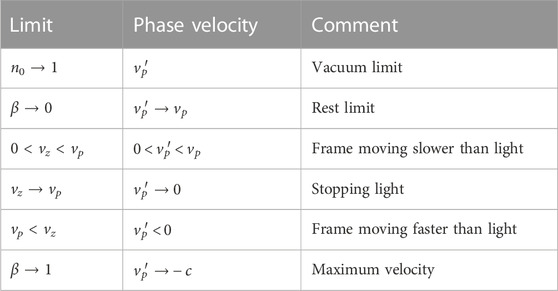
TABLE 1. The phase velocity of light observed from a moving frame in a uniform material.
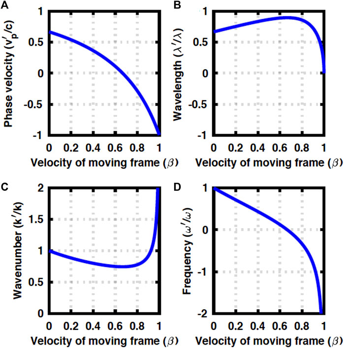
FIGURE 1. Doppler effects in a uniform material are observed from a moving frame. (A) Phase velocity changes sign at vz = vp. (B) Wavelength is red-shifted for vz < vp, while it starts to exhibit blue-shift for vp < vz. (C) Wavenumber is always positive, while (D) frequency changes sign.
2.4 Lorentz transformation in a GRIN fibre
In a GRIN fibre, the dispersion relationship is different from a uniform material, due to the band-gap opening, as we have outlined above [5, 14–17, 32]. We can obtain the corresponding dispersion relationship observed in a moving frame. The main assumption is the plane waveform of the solution along z and t and the validity of the space-time relationship by the Lorentz transformation. Consequently, we obtain
which gives
The relationship is simply summarised as the Lorentz transformation of
This is equivalent to imposing the de-Bloglie relationship in the moving frame as
which gives the Lorentz transformation of the energy-momentum relationship as
which must be valid for an arbitrary dispersion E = E(p) beyond the dispersion for a GRIN fibre. The relative symmetry against a frame exchange does not exist anymore with a material, because the rest frame with a material is different from the moving frame. Consequently, we obtain non-trivial Doppler effects, as shown in the next section.
3 Results
3.1 Doppler effects in a uniform material
First, we show numerical results in a uniform material (Figure 1). We assumed n0 = 1.5 and Δ = 0, and the wavelength of λ = 1.5 μm, considering typical parameters of a glass fibre [5]. Upon increasing the frame velocity of β, the phase velocity of
We expect a red-shift for vz < vp, since the observer in the moving frame is going away from the light source in the rest frame, such that the wavelength is elongated, while blue-shift is expected for vp < vz (Figure 1B). By assuming k′ = 2π/λ′, we obtain the wavelength in the moving frame
We confirm the appropriate limit of λ′ → λ for β → 0, while the limit of λ′ → 0 for β → 1 might be non-trivial. We expect the peak of the wavelength at
which indeed gives vz = vp. We are considering the continuous wave, emitted from the light source in the rest frame, rather than a pulsed operation. If the frame is moving above the speed of light in the rest frame, the frame is approaching the light, which was emitted earlier, such that the wavelength of the light is observed shorter than that in the rest frame. The wavenumber is always positive (Figure 1C), since the refractive index of a material is always larger than unity (n0 > 1) and the frame cannot move larger than c (β < 1).
On the other hand, the angular frequency of ω′ changes signs at vz = vp, such that the polarisation state starts to rotate in the opposite way as if the time is going backward (Figure 1D). This could be considered by defining a chiral operator defined by
In the moving frame, we consider
which changes sign at vz = vp. Therefore, the helicity is reversed upon increasing β.
In this work, we have a priori assumed that the clocks in the rest frame and the moving frame are completely synchronised, which is far from trivial [45–47, 55, 56]. In fact, the one-way speed of light cannot be measured without properly defining how to synchronize the clocks among frames [45–47, 55–57]. Therefore, it is better to measure the speed of light in round-trip (two-way) measurements. Theoretical challenges to go beyond the Lorentz invariance were also reported [46, 58]. It is beyond the scope of this work to invent the actual measurement set-up to observe the Doppler effects found in Figure 1. We have naively applied the standard special theory of relativity for the lights propagating in a material, but, the results could be interpreted in conjunction with the definition of clocks and the measurement set-up [45–47, 55–58].
3.2 Doppler effects in a GRIN fibre
Next, we consider the Doppler effects in a GRIN fibre. We assume the same core of n0 for the wavelength of λ = 1.5 μm, while the energy gap of Δ is chosen as a parameter.
The numerical results at Δ = 0.2ℏω are shown in Figure 2. The qualitative features are not changed in the case of a uniform material (Figure 1). The critical frame velocity, required to change the sign of the phase velocity, is increased due to the opening of the band gap (Figure 2A). We expect more significant red- and blue-shifts upon increasing β (Figure 2B), but k′ is always positive and ω′ changes sign, as before.
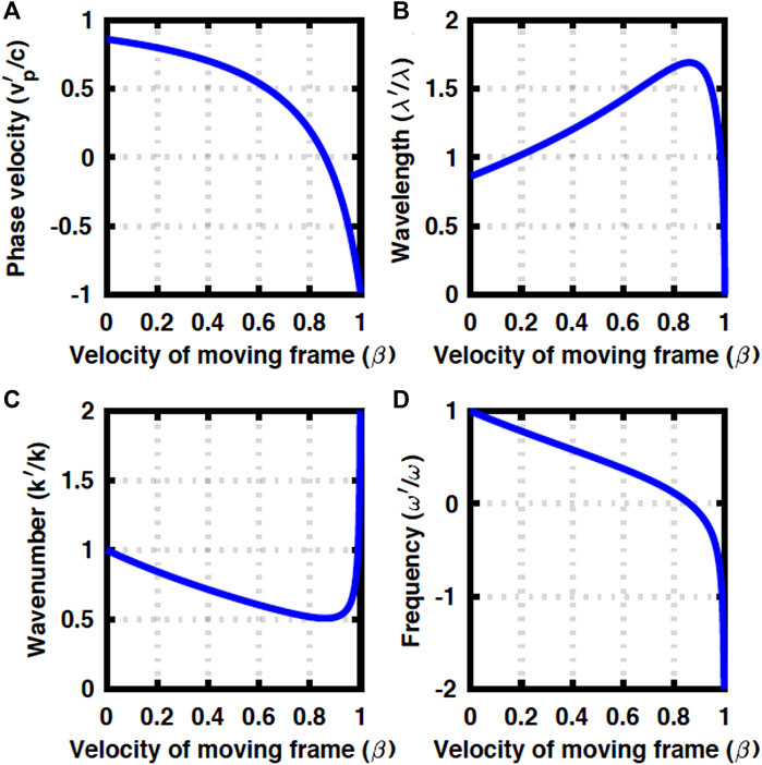
FIGURE 2. Doppler effects in a GRIN fibre at Δ = 0.2ℏω. (A) Phase velocity, (B) wavelength, (C), wavenumber, and (D) frequency.
On the other hand, for the larger Δ at 0.4ℏω, Doppler effects are even more anomalous. In this case, k′ changes sign, while ω′ is always positive. This is attributed to the larger contributions to the total energy of ℏω from orbital degrees of freedoms through the radial oscillations and/or photonic orbital angular momentum, characterised by n and m [5, 14–17, 32]. As a result, the contribution of the kinetic energy for the propagation along z is limited, such that the frame is easier to go beyond the speed of the light, which allows k′ to change the sign (Figure 3A). For k′ < 0, we have assumed k′ = −2π/λ′ to extract the wavelength of λ′ in the moving frame (Figures 3B–D).
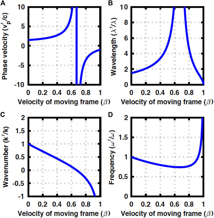
FIGURE 3. Doppler effects in a GRIN fibre at Δ = 0.4ℏω. (A) Phase velocity diverges and it could be larger than c. (B) Wavelength also diverges. (C) Wavenumber changes sign, while (D) frequency is always positive.
The maximum energy gap is Δ = 0.5ℏω, where we cannot expect any propagation along z, and the optical mode is trapped solely in the direction perpendicular to the fibre. Close to this limit, we assumed Δ = 0.49ℏω, and the results are shown in Figure 4.
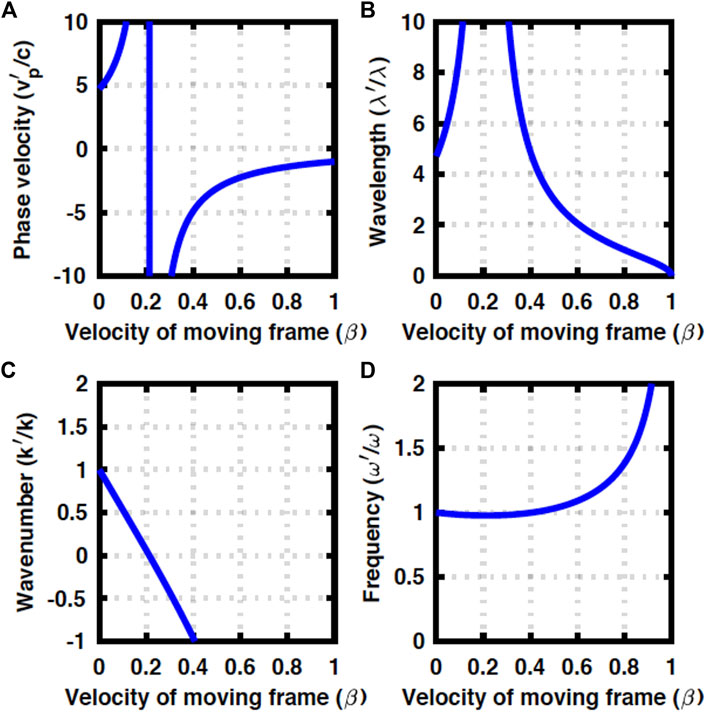
FIGURE 4. Doppler effects in a GRIN fibre at Δ = 0.49ℏω. (A) Phase velocity, (B) wavelength, (C) wavenumber, and (D) frequency. The contributions from orbital degrees of freedom are dominated by the kinetic energy along the fibre.
Regardless of the anomalous phase velocity of
As shown in Figure 5,
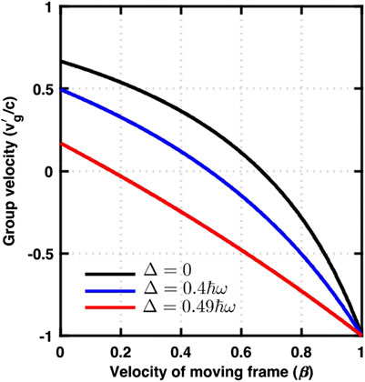
FIGURE 5. The group velocity of light in a GRIN fibre for Δ = 0 (uniform material without confinement), Δ = 0.4ℏω, and Δ = 0.49ℏω (strong confinement in the core). In all cases, the group velocity is less than the speed of light in a vacuum, satisfying the causality.
3.3 Impacts on polarisation states
Finally, we discuss the implications of our considerations for understanding the polarisation states of photons. Before discussing the application of the general theory of relativity to the GRIN fibre, we need to clarify the definition of the polarisation states, because the direction of the apparent propagation changes in the frame moving faster than the phase velocity of the light in the rest frame.
3.3.1 Lights propagating in opposite directions
We clarify the definition of the polarisation states [14], in particular, the direction of the rotation in (Figure 6). There are a lot of different choices of conventions [4, 5, 14, 20, 21], and any notation is acceptable as far as it is used consistently. We prefer to define the polarisation state, seen from the detector side because it is straightforward to describe the motion of the phase front in a standard right-handed (x, y, z) coordinate (Figure 6). We assume that the plane wave of the form eikz−iωt is propagating along the +z direction (Figure 7A), and the principal axis (S3) of the polarisation state is locked along the direction of the propagation [14]. In our definition, the left-circular-polarised state (|L⟩) is located at S3 = +1 in the normalised Poincaré sphere, while the right-circular-polarised state (|R⟩) is located at S3 = −1 (Figure 7E). These states are mirror images of each other, and in fact, a mirror can change the circular polarised states to the opposite ones [5, 14, 20, 21].
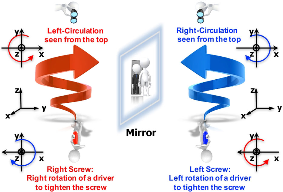
FIGURE 6. Impacts of a mirror. Polarisation states are defined by the motion of the phase front, seen from the top of the light at the detector side. The left-circular-polarised state is characterised by anti-clockwise rotation, while the right-circular-polarised state exhibits clockwise rotation. A mirror exchanges these circularly polarised states to the opposite of each other. Some researchers prefer to define by the motion of the phase front, seen from the source side similar to the definitions of right and left screws. We will not take the latter notation, and follow the mathematical notation to see the right-handed (x, y, z) coordinate to see from the top of the +z-axis.
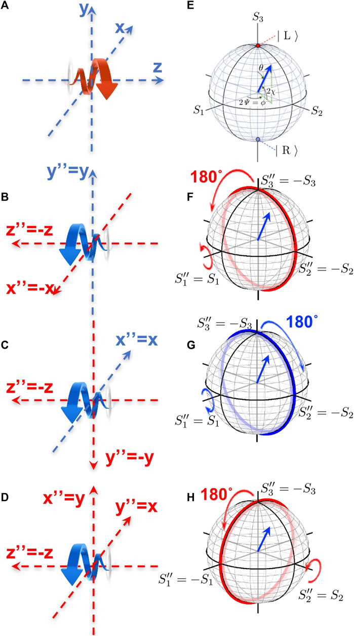
FIGURE 7. Choices of frames and polarisation states. (A) The original frame of (x, y, z) for the light propagating along the +z direction, and (E) the corresponding Poincaé sphere. (B–D) The frames of (x′′, y′′, z′′) for the light propagating along the z′′ = −z direction, and (F–H) the corresponding Poincaé spheres and their relevance to the original Poincaré sphere. Here, all frames are at rest against others. (B) (x′′, y′′, z′′) was made by the rotation along y, which is equivalent to rotate π along S1 (F). (C) (x′′, y′′, z′′) was made by the rotation along x, which is equivalent to rotate −π along S1 (G). (D) (x′′, y′′, z′′) was made by the subsequent rotation π from (B), or equivalently by the rotation of −π from (C), which is equivalent to rotate π along S2 (H).
We consider how we should describe the polarisation states for the light propagating to the opposite direction (Figure 7), since we encountered in the previous section the situation that the moving frame can go faster than the speed of the light in a material, for which the light is seen to go backward. The situation is similar to considering the reflection from a mirror (Figure 6), since a mirror changes the direction of propagation as well as the polarisation state. For example, we consider the left-circular-polarised light propagating along +z direction (Figure 7A), which is characterised by S3 = +1 (Figure 7E). We consider this light to be reflected backward without changing the rotation of the phase front (Figure 7B), while the direction of the propagation is opposite (−z). If we remain observing the phase front, seen from the +z direction, the circulation is unaffected as the anti-clockwise rotation. However, we defined that the polarisation state must be identified from the detector side, which is the −z direction (Figure 7B). Thus, we define a new frame of (x′′, y′′, z′′), assuming z′′ = −z to clarify the polarisation state. The reflected light propagating along z′′ = −z is now circulating to the clock-wise direction, seen from the +z′′ direction, thus it should be described by the right-circular-polarised state with
where n is the unit vector for the rotational axis, σ = (σ1, σ2, σ3) are Pauli matrices, and Δδ is the angle of the rotation. For example, the rotation along S1 for π (Figure 7F) is given by
while the opposite rotation for Figure 7G is described by
Similarly, the rotation along S2 for π (Figure 7H) is given by
These rotations are connected to each other. For example, the coordinate of Figure 7D is realised by rotating Figure 7B for π/2, which correspond to the π rotation along S3 [15],
In fact, we confirm
Similarly, we can rotate the coordinate of Figure 7C for π/2, which correspond to the −π rotation along S3, and we confirm
The arbitrary degree of freedom to choose the (x′′, y′′) axes is not restricted to the reflected beam. For example, if we have a linear diagonally polarised state, which is described by S2 = 1, by changing the definition of the x-axis by rotating 45°, it can also be regarded as the horizontally polarised state of S1 = 1. Therefore, the difference of the apparent polarisation states between S1 and S2 simply depends on the choice of the frame.
Among various arbitrary choices of the frame for the reflected light (Figures 7B–D7), however, one of the most sensible choices would be that of Figure 7D. In this case, the impact of the frame exchange is similar to the unitary transformation by the mirror operation of
whose impact on the spin operators would be
where * is the complex conjugate and † is the Hermite conjugate, which involves the transpose of the matrix in addition to the complex conjugate. In this convention, we understand that the polarisation state for the light propagating in the opposite direction of −z is described by the complex conjugate representation of the Lie algebra [61, 62] in the original frame as
which is consistent with Figure 7H. The complex conjugate representation also satisfies the same commutation and anti-commutation relationships with those of the original Pauli matrices [61, 62], such that we confirmed the duality of representations. Therefore, if we would like to keep working in the original frame of (x, y, z) for the light propagating in the opposite direction, we should use the complex conjugate of the spin operators, defined by
where the spinor representation of the creation and annihilation field operators are.
using the creation and annihilation operators of
3.3.2 Polarisation states observed from a moving frame
Now, we are ready to discuss the polarisation state of light, seen from an observer in the frame of (x′, y′, z′) moving as fast as the phase velocity of light in the rest frame of (x, y, z), where the fibre optic material is placed. We consider that the frame of (x′′ = y′, y′′ = x′, z′′ = −z′) is at rest against the frame of (x′, y′, z′).
First, we consider the weak coupling limit of Δ → 0, which corresponds to a uniform material with the refractive index of n0. The wavenumber of k′ is always positive, such that the momentum of p′ = ℏk′ is always pointing towards the positive +z′ direction (Figure 1C). On the other hand, ω′ changes its sign as β is increased (Figure 1D), leading to the change of the sign in
Next, we consider the polarisation state in a GRIN fibre. As far as the confinement is weak (Figure 2), the qualitative situation is the same as that for a uniform material, discussed above. Therefore, we focus on the strong coupling limit (Figure 3, 4), where k′ changes the sign upon increasing β (Figures 3C, 4C), while ω′ is always positive (Figures 3D, 4D). In these cases, the direction of the rotation of the polarisation state will not be changed by ω′, while we must judge the polarisation state seen from the direction of the propagation, which is changed. Suppose we are considering the light of the left-circularly-polarised state propagating +z direction in the frame of (x, y, z), such that the original state is S3 = 1. In the frame of (x′, y′, z′), the direction of the propagation could be changed for
In the present work, we assumed that there is no interaction between spin and orbital angular momentum in the GRIN fibre [16]. Therefore, the Doppler effects, discussed in this paper, were not coming from the impact of the spin-orbit interaction. It will be interesting to explore how the Doppler effects are modified in the presence of the spin-orbit interaction [63, 64].
3.3.3 Polarisation states at a rest frame
Finally, we would like to briefly discuss the polarisation state for a photon at a rest frame. As we have discussed above, the moving frame could move faster at the speed of the light in a material. In the GRIN fibre, for example,
4 Conclusion
We considered how the light will be seen in a material if an observer is moving as fast as the velocity of the light. As a specific example, we considered a graded index fibre, where the photon dispersion is massive due to the confinement of the orbital, which is quantised both for radial and angular directions. We see that the phase velocity could change the sign, which means that the moving frame can go faster than the speed of light in a material, as evidenced by the Cherenkov radiation [10, 11]. We found a crossover from red-shift to blue-shift as the observer increases the speed beyond the phase velocity. If the optical confinement in the fibre is strong, we found anomalous Doppler effects, with the divergent phase velocity, exceed the speed of light in a vacuum, while the group velocity is always less than c, confirming the causality and the validity of relativity. We have also discussed how the polarisation state is considered in the moving frame, for which the light could be observed to be propagating in the opposite direction from the original frame. We established that the spin operators for the light propagating in the opposite direction are described by the complex conjugate of the original spin operators, which shows the duality of the representations in SU(2) Lie algebra [61, 62]. We are not proposing to confirm this thought experiment in reality, even though it might be possible. Instead, we think our consideration might be useful as a thought-experimental platform for challenging the long-term mystery of what is a photon, imposed by Einstein [1–3].
Data availability statement
The raw data supporting the conclusion of this article will be made available by the authors, without undue reservation.
Author contributions
The author confirms being the sole contributor of this work and has approved it for publication.
Funding
This work is supported by JSPS KAKENHI Grant Number JP 18K19958.
Acknowledgments
The author would like to express sincere thanks to Prof. I. Tomita and Prof. S. Kurihara for continuous discussions and encouragement.
Conflict of interest
SS is employed by Hitachi, Ltd.
Publisher’s note
All claims expressed in this article are solely those of the authors and do not necessarily represent those of their affiliated organizations, or those of the publisher, the editors and the reviewers. Any product that may be evaluated in this article, or claim that may be made by its manufacturer, is not guaranteed or endorsed by the publisher.
References
1. Einstein A. Concerning an heuristic point of view toward the emission and transformation of light. Ann Phys (1905) 17:132–48. doi:10.1002/andp.19053220607
2. Einstein A. On the electrodynamics of moving bodies. Ann Phys (1905) 17:891–921. doi:10.1002/andp.19053221004
3. Lehner M. The cambridge companion to Einstein (cambridge companions to philosophy). Cambridge: Cambridge University Press (2014). doi:10.1017/CCO9781139024525
5. Yariv Y, Yeh P. Photonics: Optical electronics in modern communications. Oxford: Oxford University Press (1997).
7. Nienhuis G. Doppler effect induced by rotating lenses. Opt Comm (1996) 132:8–14. doi:10.1016/0030-4018(96)00295-7
8. Halimeh JC, Thompson RT. Fresnel-fizeau drag* invisibility conditions for all inertial observers. Phys Rev A (2016) 93:033819. doi:10.1103/PhysRevA.93.033819
9. Halimeh JC, Thompson RT, Wegener M. Invisibility cloaks in relativistic motion. Phys Rev A (2016) 93:013850. doi:10.1103/PhysRevA.93.013850
10. Cherenkov PA. Visible radiation produced by electrons moving in a medium with velocities exceeding that of light. Phys Rev (1937) 52:378–9. doi:10.1103/PhysRev.52.378
11. Cherenkov PA. At the threshold of discovery. Nucl Instrum Methods Phys Res A (1986) 248:1–4. doi:10.1016/0168-9002(86)90487-0
12. Baryshevsky VG, Gurnevich EA. Cherenkov and parametric (quasi-Cherenkov) radiation produced by a relativistic charged particle moving through a crystal built from metallic wires. Nucl Instrum Methods Phys Res B (2017) 402:30–4. doi:10.1016/j.nimb.2017.03.015
13. Fukuda Y, Hayakawa T, Ichihara E, Inoue K, Ishihara K, Ishino H, et al. Evidence for oscillation of atmospheric neutrinos. Phys Rev Lett (1998) 81:1562–7. doi:10.1103/PhysRevLett.81.1562
14. Saito S. Spin of photons: Nature of polarisation (2023). Available at: https://arxiv.org/abs/2303.17112 (Accessed March 30, 2023).
15. Saito S. Quantum commutation relationship for photonic orbital angular momentum (2023). Available at: https://arxiv.org/abs/2303.17116 (Accessed March 30, 2023).
16. Saito S. Spin and orbital angular momentum of coherent photons in a waveguide (2023). Available at: https://arxiv.org/abs/2303.17116 (Accessed March 30, 2023).
17. Saito S. Dirac equation for photons: Origin of polarisation (2023). Available at: https://arxiv.org/abs/2303.18196.
21. Gil JJ, Ossikovski R. Polarized light and the mueller matrix approach. London: CRC Press (2016).
22. Pedrotti FL, Pedrotti LM, Pedrotti LS. Introduction to optics. New York: Pearson Education (2007).
24. Grynberg G, Aspect A, Fabre C. Introduction to quantum optics: From the semi-classical approach to quantized light. Cambridge: Cambridge University Press (2010).
27. Nagaosa N. Quantum field theory in condensed matter Physics. Berlin, Heidelberg: Springer (1999).
29. Altland A, Simons B. Condensed matter field theory. Cambridge: Cambridge University Press (2010).
30. Stokes GG. On the composition and resolution of streams of polarized light from different sources. Trans Cambridge Phil Soc (1851) 9:399–416. doi:10.1017/CBO9780511702266.010
32. Allen L, Beijersbergen MW, Spreeuw RJC, Woerdman JP. Orbital angular momentum of light and the transformation of Laguerre-Gaussian laser modes. Phys Rev A (1992) 45:8185–9. doi:10.1103/PhysRevA.45.8185
33. v Enk SJ, Nienhuis G. Commutation rules and eigenvalues of spin and orbital angular momentum of radiation fields. J Mod Opt (1994) 41:963–77. doi:10.1080/09500349414550911
34. Leader E, Lorcé C. The angular momentum controversy: What’s it all about and does it matter? Phys Rep (2014) 541:163–248. doi:10.1016/j.physrep.2014.02.010
35. Barnett SM, Allen L, Cameron RP, Gilson CR, Padgett MJ, Speirits FC, et al. On the natures of the spin and orbital parts of optical angular momentum. J Opt (2016) 18:064004. doi:10.1088/2040-8978/18/6/064004
36. Bliokh KY, Rodríguez-Fortuño FJ, Nori F, Zayats AV. Spin-orbit interactions of light. Nat Photon (2015) 9:796–808. doi:10.1038/NPHOTON.2015.201
37. Chen XS, Lü XF, Sun WM, Wang F, Goldman T. Spin and orbital angular momentum in gauge theories: Nucleon spin structure and multipole radiation revisited. Phys Rev Lett (2008) 100:232002. doi:10.1103/PhysRevLett.100.232002
38. Ji X. Comment on “Spin and orbital angular momentum in gauge theories: Nucleon spin structure and multipole radiation revisited”. Phys Rev Lett (2010) 104:039101. doi:10.1103/PhysRevLett.104.039101
39. Yang LP, Jacob Z. Non-classical photonic spin texture of quantum structured light. Comm Phys (2021) 4:221. doi:10.1038/s42005-021-00726-w
40. Yang LP, Khosravi F, Jacob Z. Quantum field theory for spin operator of the photon. Phys Rev Res (2022) 4:023165. doi:10.1103/PhysRevResearch.4.023165
41. Kawakami S, Nishizawa J. An optical waveguide with the optimum distribution of the refractive index with reference to waveform distortion. IEEE Trans Microw Theor Techn. (1968) 16:814–8. doi:10.1109/TMTT.1968.1126797
42. Joannopoulos JD, Johnson SG, Winn JN, Meade RD. Photonic crystals: Molding the flow og light. New York, NY: Princeton Univ. Press (2008).
43. Weinberg S. The quantum theory of fields: Foundations. Cambridge: Cambridge University Press (2005).
44. Brecher K. Is the speed of light independent of the velocity of the source? Phys Rev Lett (1977) 39:1051–4. doi:10.1103/PhysRevLett.39.1051
45. Will CM. Clock synchronization and isotropy of the one-way speed of light. Phys Rev D (1992) 45:403–11. doi:10.1103/PhysRevD.45.403
46. Liberati S, Maccione L. Lorentz violation: Motivation and new constraints. Ann Rev Nuc Part Sci (2009) 59:245–67. doi:10.1146/annurev.nucl.010909.083640
47. Anderson R, Vetharaniam I, Stedman GE. Conventionality of synchronisation, gauge dependence and test theories of relativity. Phys Rep (1998) 295:93–180. doi:10.1016/S0370-1573(97)00051-3
48. Bardeen J, Cooper LN, Schrieffer JR. Theory of superconductivity. Phys Rev (1957) 108:1175–204. doi:10.1103/PhysRev.108.1175
49. Anderson PW. Random-phase approximation in the theory of superconductivity. Phys Rev (1958) 112:1900–16. doi:10.1103/PhysRev.112.1900
50. Bogoljubov NN. On a new method in the theory of superconductivity. IL Nuovo Cimento (1958) 7:794–805. doi:10.1007/BF02745585
51. Nambu Y. Quasi-particles and gauge invariance in the theory of superconductivity. Phys Rev (1960) 117:648–63. doi:10.1103/PhysRev.117.648
53. Goldstone J, Salam A, Weinberg S. Broken symmetries. Phy Rev (1962) 127:965–70. doi:10.1103/PhysRev.127.965
54. Higgs PW. Broken symmetries and the masses of gauge bosons. Phys Lett (1962) 12:508–9. doi:10.1103/PhysRevLett.13.508
55. Zhang YZ. Test theories of special relativity. Gen Relat Gravit (1995) 27:475–93. doi:10.1007/BF02105074
56. Szostek R. Derivation of all linear transformations that meet the results of michelson–morley’s experiment and discussion of the relativity basics. Mosc Univ. Phys. (2020) 75:684–704. doi:10.3103/S0027134920060181
57. Szostek K, Szostek R. The concept of a mechanical system for measuring the one-way speed of light. Tech Trans (2023) 120:1–9. doi:10.37705/TechTrans/e2023003
58. Szostek K, Szostek R. The existence of a universal frame of reference, in which it propagates light, is still an unresolved problem of physics. Jordan J Phys (2022) 15:457–67. doi:10.47011/15.5.3
59. Jones RC. A new calculus for the treatment of optical systems i. description and discussion of the calculus. J Opt Soc Am (1941) 31:488–93. doi:10.1364/JOSA.31.000488
61. Georgi H. Lie algebras in particle Physics: From isospin to unified theories (Frontiers in Physics). Massachusetts: Westview Press (1999).
63. Shao Z, Zhu J, Chen Y, Zhang Y, Yu S. Spin-orbit interaction of light induced by transverse spin angular momentum engineering. Nat Comm (2018) 9:926. doi:10.1038/s41467-018-03237-5
64. Bliokh K. Geometrodynamics of polarized light: Berry phase and spin Hall effect in a gradient-index medium. J Opt A: Pure Appl Opt (2009) 11:094009. doi:10.1088/1464-4258/11/9/094009
65. Saito S. Photonic quantum chromo-dynamics. Available at: https://arxiv.org/abs/2304.01217 (Accessed March 30, 2023).
66. Saito S. Macroscopic single-qubit operation for coherent photons. Available at: https://arxiv.org/abs/2304.00013 (Accessed March 30, 2023).
Keywords: Stokes parameters, Poincaré sphere, polarisation, spin angular momentum, SU(2), coherent state
Citation: Saito S (2023) Special theory of relativity for a graded index fibre. Front. Phys. 11:1225387. doi: 10.3389/fphy.2023.1225387
Received: 19 May 2023; Accepted: 18 July 2023;
Published: 02 August 2023.
Edited by:
Xinzhong Li, Henan University of Science and Technology, ChinaReviewed by:
Hehe Li, Henan University of Science and Technology, ChinaRoman Szostek, Rzeszów University of Technology, Poland
Copyright © 2023 Saito. This is an open-access article distributed under the terms of the Creative Commons Attribution License (CC BY). The use, distribution or reproduction in other forums is permitted, provided the original author(s) and the copyright owner(s) are credited and that the original publication in this journal is cited, in accordance with accepted academic practice. No use, distribution or reproduction is permitted which does not comply with these terms.
*Correspondence: Shinichi Saito, shinichi.saito.qt@hitachi.com