Artifact suppression using cross-circular polarization for millimeter-wave imaging
 Shuang Qiu1,2
  Yongshen Zhang
 Yayun Cheng
- 1School of Electronics and Information Engineering, Harbin Institute of Technology, Harbin, China
- 2Department of Engineering Physics, Tsinghua University, Beijing, China
Millimeter-wave imaging is widely applied to radar detection, personnel security inspection, environmental perception, and so on. Multipath artifact is a common phenomenon in active millimeter-wave (AMMW) imaging and is difficult to be removed. The suppression methods in image reconstruction and post-processing stage are usually complex or time-consuming. This report proposes a cross-polarization method to suppress multipath artifacts between equivalent two-cylinder structures before image reconstruction. The physical mechanisms of co-polarization and cross-polarization imaging are revealed. The suppression effectiveness is demonstrated by conducting W-band AMMW imaging simulation and measurement experiments of a typical multipath scenario at the central frequency of 100 GHz (97 ∼103 GHz). The proposed method can directly reconstruct the image with artifact suppression and reduce the pressure of post-processing.
1 Introduction
Personnel security inspection is an important means to maintain the safety of people and society in public places. X-ray imaging is widely used to luggage security inspection, but it is improper to use to human body security screening due to privacy and security issues. At present, the most common screening system is the metal detector based on electromagnetic interactions Paulter [1], which usually has a high false alarm rate and cannot detect non-metallic hidden objects. Due to the penetration capability of many non-metallic materials, millimeter-wave sensing is widely applied to radar detection, personnel security inspection, environmental perception Bjarnason et al. [2]; Hang et al. [3]; Salmon [4]; Cheng et al. [5]. Active millimeter-wave (AMMW) imaging has become the most promising method for personnel security screening because it has no ionizing radiation compared to X-ray imaging. In recent years, many AMMW imaging systems have been developed and even commercially applied to airports, railway stations, large event venues, and other public places Wang et al. [6]; Gao et al. [7]; Liu et al. [8].
Image reconstruction is a key task for AMMW imaging. Conventional imaging algorithms regard the target as a mass of independent scattering points and so assume that the millimeter-wave scattered back received by the receiver is only scattered once by targets. This approximation can lead to simpler and faster image reconstruction. However, it cannot consider the multiple scatterings around arms and legs. Multipath artifacts from high-order scattering occur in reconstructed images Yuan et al. [9]; Meng et al. [10], which has a negative impact on the detection of hidden objects in practical security inspection applications. Performing specific postures such as spreading legs and raising hands are useful to reduce multipath artifacts. But these postures will increase the passing time of each person, and lead to great inconveniences at checkpoints with large traffic volumes. In addition, it is difficult to eliminate artifacts directly through image post-processing algorithms. To suppress multipath artifacts, some previous works have been conducted in the image reconstruction stage. Bi-static/multi-static imaging can effectively suppress high-order artifacts of concave objects Liang et al. [11]; Gonzalez-Valdes et al. [12]. For mono-static configurations, the concept of shooting and bouncing rays method is used to build a more accurate analytical forward model, which contributes to producing accurate images without strong high-order scattering Liang et al. [13]. The stationary phase method and circularly polarized measurements are used to correct the image deformation of edges for dihedral structures Si et al. [14]. The above processing methods are effective. Meanwhile, they are usually complex and time-consuming or require high hardware costs.
For practical security inspection scenarios, multipath artifacts mainly occur in the areas around the legs and arms. The equivalent structure is not a dihedral structure but two spaced cylinders or elliptical cylinders. Previous works about artifact suppression focused on AMMW imaging below Ka-band (26.5 ∼40 GHz) Sheen et al. [15]; Si et al. [14]. Few studies have been reported on W-band (75 ∼110 GHz) Existing systems usually have a co-linear polarization transceiver. Using multiple polarization imaging can obtain more information of observation scenes Guo et al. [16]; Cheng et al. [17]; Zhu et al. [18].
In this report, a cross-polarization method to suppress multipath artifacts between two spaced cylinders for W-band AMMW imaging is proposed. The generation mechanism of multipath artifacts is explained by analyzing polarized millimeter-wave reflections between two spaced cylinders. The physical mechanisms of co-polarized and cross-polarized imaging are revealed. Simulation and measurement imaging experiments at the central frequency of 100 GHz (97 ∼103 GHz) have been conducted to verify the proposed method. The rest of this article is organized as follows. The principle of the Principle of the cross-polarization method are described in Section 2. In Section 3, the experimental results are discussed. Finally, the discussion is drawn in Section 4.
2 Method
Holographic imaging is the main mode of AMMW imaging Sheen et al. [19]; Qiao et al. [20]; Gao et al. [21]; Wu et al. [22]. Firstly, receiving the millimeter-wave signals scattered on the objects; Then, measuring phase information through heterodyne mixing; Finally, inverting the scene image based on the intensity and phase information. The transmitting and receiving antenna (TX and RX) positions of the millimeter-wave direct holographic imaging system are adjacent. The spherical wave exp (−ikr)/r (where r is the distance) emitted by the transmitting antenna is transmitted to the human body, and then scattered back to the receiving antenna. Each point on the surface of the human body scatters the millimeter-wave signal, and the receiving antenna receives the superpositions of the scattered signals at various positions on the object surfaces. Under the assumption of Born primary scattering approximation with isotropic scattering, the backscattered millimeter-wave received by the receiving antenna can be expressed as
where s (x0, y0, ω) is the sampled data at point (x0, y0) with an angular frequency ω, f (x, y, z) represents the complex reflection coefficient of the observation object at the position (x, y),
As shown in Figure 1B, the areas around legs and arms in Figure 1A can be equivalent to two cylinders or elliptical cylinders with certain spacing. The millimeter-wave energy returned after secondary scattering produces equivalent artifacts between the two cylinders. In the expression of Eq. 1, the distance between the transceiver antenna and the object is determined by the optical path of the millimeter-wave reflection. For the primary scattering approximation, the millimeter-wave reflection after secondary scattering will be considered to be scattered once with the same optical path Sheen et al. [19]; Cheney [23]. In other words, the artifact is on a circle with the center of the transceiver antenna phase and the radius of a half optical path. In the image reconstructed by conventional algorithms, a virtual object (i.e., highlighted areas that is similar to real objects) will appear at the equivalent location of the multipath artifact.
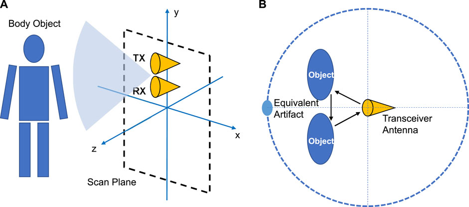
FIGURE 1. (A) Schematic of millimeter-wave direct holographic imaging for human body imaging. (B) Schematic diagram of multipath artifacts. Since the transmitting and receiving antennas are approximately at the same position in actual operation, they are represented by a transceiver antenna.
Circular polarization waves have rotational orthogonality. Specifically speaking, if an antenna only has a left-hand circular polarization (LHCP), the right-hand circular polarization (RHCP) waves cannot be received by the antenna, and vice versa. As shown in Figure 2A, when an LHCP wave is reflected by a symmetrical object (plane or spherical surface), the polarization state of the reflected wave rotates in the orthogonal direction relative to the incident wave. That is, the reflected wave becomes an RHCP wave. As shown in Figure 2B, for the artifact area of two spaced objects, the circular polarization wave reaching the receiving antenna will have the same polarization direction as the incident wave after being scattered even times. Therefore, if the circular polarization directions of the transmitting and receiving antennas are orthogonal, the equivalent artifacts resulting from even-order scatterings are automatically filtered. In other words, the receiving antenna only receives the reflected waves resulting from odd-order scatterings. In practice, for two spaced cylinder structures, the energy of backscattered waves resulting from more than second-order scattering is very small. The main contribution of the multipath artifact is the secondary (second-order) scattering. If we use a cross-circular polarization transceiver, multipath artifacts will be effectively suppressed and so the image quality will be improved.
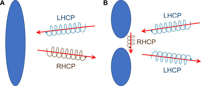
FIGURE 2. Schematic diagram of the reflection of a circularly polarized wave. The polarization of the reflected wave changes to the orthogonal direction relative to the incident wave. (A) Single scattering on the object. (B) Multiple scatterings between two spaced objects.
3 Results and discussion
3.1 Simulation experiments
To preliminarily verify the application of cross-circular polarization imaging, we have conducted simulation experiments based on Altair FEKO calculation. As shown in Figure 3A, two spaced aluminum cylinders were used to simulate the body, arms, and legs that produce multipath artifacts during security inspection. The radius of each cylinder is 0.05 m, the height is 0.04 m, and the center distance between the two cylinders is 0.12 m. The calculation frequency is set to 100 GHz. We have conducted two simulations to comparatively demonstrate the presented cross-polarization imaging method. One is cross-circular polarization imaging, the other one is traditional co-linear polarization imaging. The simulated antenna array is in the form of a 100 × 100 square matrix array. The side length of the antenna array is 0.5 m and the imaging distance is 1 m. The antenna array is placed along two directions (two cases) to observe for comparison. (1) The observation direction is along the y-axis, and the antenna array plane is parallel to the xoz-plane. (2) The observation direction is along the z-axis, and the antenna array plane is perpendicular to the z-axis. This case is consistent with the scenario of practical personnel security screening.
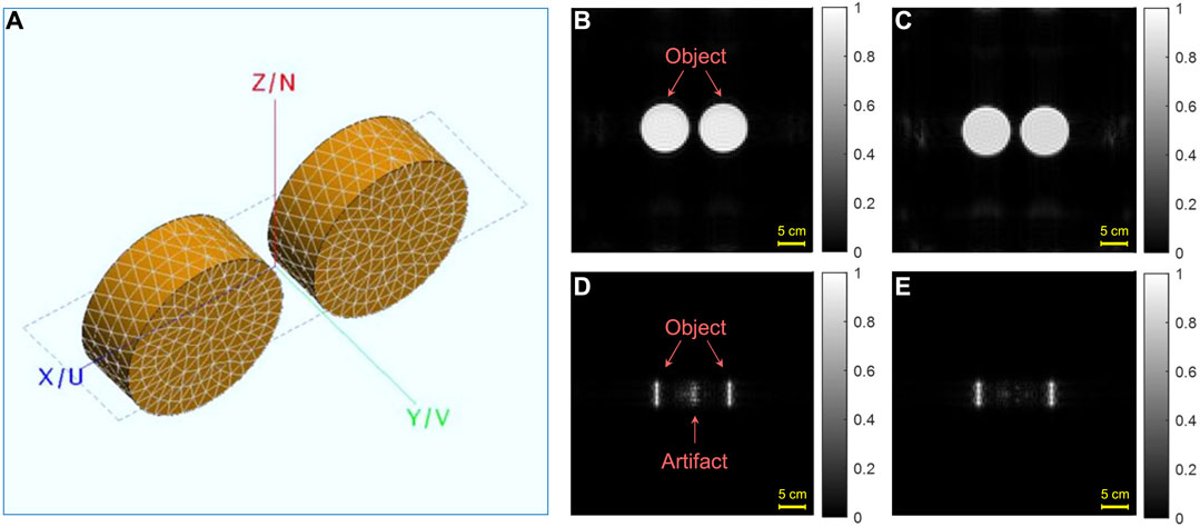
FIGURE 3. Simulated imaging results of two spaced aluminum cylinders. (A) 3D mesh structure diagram of two spaced aluminum cylinders for imaging simulation. (B) Co-linear polarization imaging (Conventional imaging) in the direction along y-axis. (C) Cross-circular polarization imaging in the direction along y-axis. (D) Co-linear polarization imaging (Conventional imaging) in the direction along z-axis. (E) Cross-circular polarization imaging in the direction along z-axis.
Figures 3B–E shows simulated imaging results of two spaced aluminum cylinders. Co-linear polarization imaging (conventional imaging) results are shown in Figures 3B, D. Cross-circular polarization imaging results are shown in Figures 3C, E. Because there is nearly no multiple scattering in the first case, nearly no multipath artifact appears in both Figures 3B, C. Co-linear and cross-circular polarization systems have similar reconstructed images. Note that, this case is only used to illustrate the artifact-free phenomenon of the plane object. As shown in Figures 3D, E, because the receiving antenna mainly receives the backscattered waves, two cylinder objects form two bright bands in the AMMW image. The other surfaces of the two cylinders scatter the waves in other directions. Note that there are obvious multipath artifacts between two cylinders in Figure 3D, which is the result of conventional co-liner polarization imaging. By using a cross-circular polarization transceiver, most multipath artifacts are effectively suppressed in Figure 3E. Except for the single and second scattering, much of the energy emitted by the transmitter penetrates through the space between two cylinders. In other words, the energies of backscattered waves resulting from more than second-order scattering are indeed very small due to the cylindrical structure and the certain spacing.
3.2 Measurement experiments
To further verify the effectiveness of the cross-circular polarization method, measurement experiments of two spaced aluminum cylinders have been conducted. As shown in Figure 4A, the experimental setup is mainly composed of a vector network analyzer (VNA) up to 67 GHz, millimeter-wave frequency multiplier (FM), 97–103 GHz circularly polarized antenna, and mechanical scanning platform. VNA is used for millimeter-wave generation and data acquisition. FM modules play the role of signal amplification and frequency conversion. The circularly polarized antenna consists of a circular horn, a circularly polarized waveguide, an ortho-mode transducer (OMT), a matched load, and a rectangular waveguide that connects with the radiometer Cheng et al. [24]. Due to the technological limitation of OMT, our circularly polarized antenna has a bandwidth of 6 GHz (97 ∼103 GHz). The antennas of co-linear polarization imaging are two standard square horns. To facilitate scanning imaging, two spaced aluminum cylinders are put on the scanning platform to form the relative motion with the transceiver. The plane scanning of the platform can be equivalent to that of the transceiver in Figure 1A.
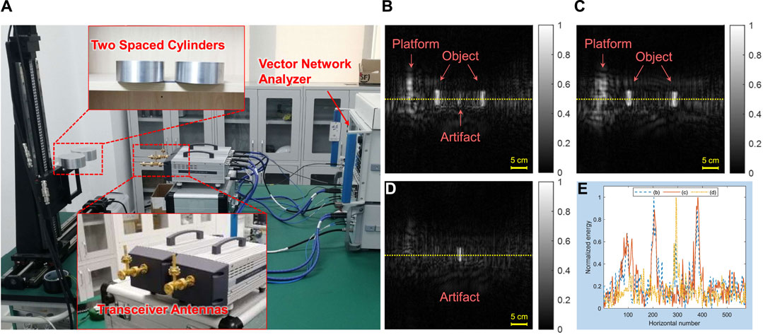
FIGURE 4. Measured imaging results of two spaced aluminum cylinders along the observation direction. (A) Measurement experiment setup of co-polarized and cross-polarized imaging for two spaced aluminum cylinders at the working frequency of 97 ∼103 GHz. (B) Co-linear polarization imaging (Conventional imaging). (C) Cross-circular polarization imaging. (D) Co-circular polarization imaging. (E) Normalized pixel values of the yellow dashed line in (B), (C), and (D).
Figures 4B–E shows measured imaging results of two spaced aluminum cylinders. There are many clutter waves resulting from the mechanical scanning platform, which includes the scan column and the support table. As shown in Figure 4B, there are obvious multipath artifacts between two spaced cylinders. Two cylinder objects form two bright bands in the AMMW image. On the contrary, multipath artifacts are obviously suppressed by orthogonal circular polarization filtering in Figure 4C. To verify the energy distribution of the artifact suppression, a co-circular polarization imaging has been carried out and the image is shown in Figure 4D. The bright band in the middle of the image denotes equivalent artifacts resulting from even-order scatterings. In order to compare the effect of artifact suppression more intuitively, the pixels along the yellow dashed lines in Figures 4B–D have been extracted and depicted in Figure 4E. The average of a certain width of data along the yellow dotted line is calculated to reduce the misjudgment from the randomness of a single line. Each data have been normalized. From Figure 4E, the artifact peak between two spaced cylinders is clearly suppressed by cross-circular polarization filtering.
3.3 Discussion
In both simulated and measured experiments, the objects we used were pure aluminum cylinders with smooth surfaces. Radar imaging relies on backscattered echo signals. For the side of the cylinder, only a small area of the surface can reflect a strong echo signal. The backscatter of other facets is extremely weak and close to the background echo energy (almost invisible compared to the strong reflection region). Therefore, in both simulation and measured experiments, only strong reflection features like long strips can be obtained when imaging the side of the cylinder. For the variation of the platform profile in Figures 4B, C, this is caused by the co-polarization and cross-polarization differences. The vertical bar of the platform is a complex groove shape, and the rotating lead screw is installed inside. The scattering phenomenon of millimeter-wave in it is very complex, and this complex process is closely related to polarization. Due to the complexity of the structure, the image characteristics will be different for co-polarized and cross-polarized imaging.
In our experiments, we installed transmitting and receiving antennas separately. So, there are some distances between them. When the transceiver antenna has a certain spacing, it will affect the position and relative intensity of the equivalent artifact and the cylinder bright strip. Transceiver antennas that are not at the same location still satisfy the physical laws of co-polarized and cross-polarized imaging in Figure 2. Therefore, whether the transmitting and receiving antennas are at the same location does not significantly affect the effectiveness of the proposed method.
To quantitatively evaluate the effect of artifact suppression, we calculated the degree of reduction in the brightness of the artifact region by counting the data from multiple simulated and measured experiments. For the multiple simulation data in Figure 3, the brightness is reduced by about 6.7 dB after artifact suppression compared to the brightness before suppression. For the measured imaging data in Figure 4, the brightness is reduced by about 6.1 dB after artifact suppression compared to the brightness before suppression. It can be seen that the proposed method can reduce the artifact brightness by at least 6 dB. This makes the brightness of artifacts close to that of the background, thus reducing the impact of artifacts on image quality.
4 Conclusion
In summary, we report a cross-polarization method to suppress multipath artifacts for human body 97 ∼103 GHz AMMW imaging. Multipath artifacts around legs and arms have a negative impact on the image quality and the accuracy of object detection. Two cylinders or elliptical cylinders with certain spacing are equivalent to the areas around the legs and arms. The cylindrical structure and the certain spacing lead to the energies of backscattered waves resulting from more than second-order scattering being very small. So the cross-circular polarization transceiver can effectively suppress these artifacts due to its rotational orthogonality. Imaging experimental results demonstrate the presented method, which can suppress artifacts before image reconstruction and reduce the artifact brightness by at least 6 dB. In the near future, a miniaturized fast AMMW imaging system with cross-polarization transceivers will be developed and is expected to be commercially available in surveillance scenarios.
Data availability statement
The raw data supporting the conclusion of this article will be made available by the authors, without undue reservation.
Author contributions
SQ, JL, and YC contributed to conception and design of the study. JL and YZ carried out experiments. SQ and JL performed the data analysis. SQ and JL wrote the first draft of the manuscript. YZ and YC wrote sections of the manuscript. All authors contributed to manuscript revision, read, and approved the submitted version.
Funding
This work was supported in part by the National Natural Science Foundation of China (NSFC) under Grants 61901242 and 61731007, the Fundamental Research Funds for the Central Universities under Grants FRFCU5710052821, and the assisted project by Heilong Jiang Postdoctoral Funds for scientific research initiation under Grant LBH-Q21093.
Acknowledgments
The authors thank Dr. Lingbo Qiao, Dr. Ziye Wang, and Prof. Ziran Zhao from Tsinghua University for the simulation and experiment discussion.
Conflict of interest
The authors declare that the research was conducted in the absence of any commercial or financial relationships that could be construed as a potential conflict of interest.
Publisher’s note
All claims expressed in this article are solely those of the authors and do not necessarily represent those of their affiliated organizations, or those of the publisher, the editors and the reviewers. Any product that may be evaluated in this article, or claim that may be made by its manufacturer, is not guaranteed or endorsed by the publisher.
References
1. Paulter NG. Test methods to rigorously, reproducibly, and accurately measure the detection performance of walk-through metal detectors. J Test Eval (2019) 48:20180220–1711. doi:10.1520/jte20180220
2. Bjarnason JE, Chan TLJ, Lee AWM, Celis MA, Brown ER. Millimeter-wave, terahertz, and mid-infrared transmissionthrough common clothing. Appl Phys Lett (2004) 85:519–21. doi:10.1063/1.1771814
3. Hang C, Hai-Tao Z, Han-dan J, Shi-Yong L, Hou-Jun S. Three-dimensional near-field surveillance imaging using w-band system. J Infrared Millimeter Waves (2017) 36:408–14.
4. Salmon NA. Outdoor passive millimeter-wave imaging: Phenomenology and scene simulation. IEEE Trans Antennas Propagation (2017) 66:897–908. doi:10.1109/tap.2017.2781742
5. Cheng Y, Wang Y, Niu Y, Rutt H, Zhao Z. Physically based object contour edge display using adjustable linear polarization ratio for passive millimeter-wave security imaging. IEEE Trans Geosci Remote Sens (2021) 59:3177–91. doi:10.1109/tgrs.2020.3011179
6. Wang Z, Chang T, Cui H-L. Review of active millimeter wave imaging techniques for personnel security screening. IEEE Access (2019) 7:148336–50. doi:10.1109/access.2019.2946736
7. Gao X, Li C, Gu S, Fang G. Study of a new millimeter-wave imaging scheme suitable for fast personal screening. IEEE Antennas Wireless Propagation Lett (2012) 11:787–90. doi:10.1109/lawp.2012.2203574
8. Liu T, Zhao Y, Wei Y, Zhao Y, Wei S. Concealed object detection for activate millimeter wave image. IEEE Trans Ind Electron (2019) 66:9909–17. doi:10.1109/tie.2019.2893843
9. Yuan M, Zhang Q, Li Y, Yan Y, Zhu Y. A suspicious multi-object detection and recognition method for millimeter wave sar security inspection images based on multi-path extraction network. Remote Sensing (2021) 13:4978. doi:10.3390/rs13244978
10. Meng Y, Lin C, Zang J, Qing A, Nikolova NK. General theory of holographic inversion with linear frequency modulation radar and its application to whole-body security scanning. IEEE Trans Microwave Theor Tech (2020) 68:4694–705. doi:10.1109/tmtt.2020.3016323
11. Liang B, Shang X, Zhuge X, Miao J. Bistatic cylindrical millimeter-wave imaging for accurate reconstruction of high-contrast concave objects. Opt Express (2019) 27:14881–92. doi:10.1364/oe.27.014881
12. Gonzalez-Valdes B, Alvarez Y, Mantzavinos S, Rappaport CM, Las-Heras F, Martinez-Lorenzo JA. Improving security screening: A comparison of multistatic radar configurations for human body imaging. IEEE Antennas Propagation Mag (2016) 58:35–47. doi:10.1109/map.2016.2569447
13. Liang B, Shang X, Zhuge X, Miao J. Accurate near-field millimeter-wave imaging of concave objects—A case study of dihedral structures under monostatic array configurations. IEEE Trans Geosci Remote Sensing (2020) 58:3469–83. doi:10.1109/tgrs.2019.2957315
14. Si W, Zhuge X, Pu Z, Miao J. Accurate near-field millimeter-wave imaging of concave objects using circular polarizations. Opt Express (2021) 29:25142–60. doi:10.1364/oe.430950
15. Sheen DM, McMakin DL, Lechelt WM, Griffin JW. Circularly polarized millimeter-wave imaging for personnel screening. Proc SPIE (2005) 5789:117–26.
16. Guo Y, Jiao L, Wang S, Wang S, Liu F, Hua W. Fuzzy superpixels for polarimetric sar images classification. IEEE Trans Fuzzy Syst (2018) 26:2846–60. doi:10.1109/tfuzz.2018.2814591
17. Cheng Y, You Y, Zhu D, Wang Y, Zhao Z. Reflection removal using dual-polarization and saliency in millimeter-wave and terahertz imaging. IEEE Trans Geosci Remote Sensing (2021) 59:9439–47. doi:10.1109/tgrs.2021.3049554
18. Zhu D, Wang X, Cheng Y, Li G. Vessel target detection in spaceborne–airborne collaborative sar images via proposal and polarization fusion. Remote Sensing (2021) 13:3957. doi:10.3390/rs13193957
19. Sheen DM, McMakin DL, Hall TE. Three-dimensional millimeter-wave imaging for concealed weapon detection. IEEE Trans Microwave Theor Tech (2001) 49:1581–92. doi:10.1109/22.942570
20. Qiao L, Wang Y, Zhao Z, Chen Z. Range resolution enhancement for three-dimensional millimeter-wave holographic imaging. IEEE Antennas Wireless Propagation Lett (2016) 15:1422–5. doi:10.1109/lawp.2015.2511302
21. Gao J, Qin Y, Deng B, Wang H, Li X. Novel efficient 3d short-range imaging algorithms for a scanning 1d-mimo array. IEEE Trans Image Process (2018) 27:3631–43. doi:10.1109/tip.2018.2821925
22. Wu S, Wang H, Li C, Liu X, Fang G. A modified omega-k algorithm for near-field single-frequency mimo-arc-array-based azimuth imaging. IEEE Trans Antennas Propagation (2021) 69:4909–22. doi:10.1109/tap.2020.3048578
23. Cheney M. A mathematical tutorial on synthetic aperture radar. SIAM Rev (2001) 43:301–12. doi:10.1137/s0036144500368859
Keywords: millimeter-wave imaging, polarization, artifact suppression, image reconstruction, security inspection
Citation: Qiu S, Lu J, Zhang Y and Cheng Y (2023) Artifact suppression using cross-circular polarization for millimeter-wave imaging. Front. Phys. 11:1119806. doi: 10.3389/fphy.2023.1119806
Received: 09 December 2022; Accepted: 13 March 2023;
Published: 22 March 2023.
Edited by:
Jacques Kengne, University of Dschang, CameroonCopyright © 2023 Qiu, Lu, Zhang and Cheng. This is an open-access article distributed under the terms of the Creative Commons Attribution License (CC BY). The use, distribution or reproduction in other forums is permitted, provided the original author(s) and the copyright owner(s) are credited and that the original publication in this journal is cited, in accordance with accepted academic practice. No use, distribution or reproduction is permitted which does not comply with these terms.
*Correspondence: Yayun Cheng, chengyy@hit.edu.cn