Stability improvement of multi-beam picosecond–petawatt laser system for ultrahigh peak-power applications
 Shunxing Tang
 Yajing Guo
 Pengqian Yang
 Xiuqing Jiang1,2
 - 1National Laboratory on High Power Lasers and Physics, Shanghai Institute of Optics and Fine Mechanics, Chinese Academy of Sciences, Shanghai, China
- 2Collaborative Innovation Center of IFSA, Shanghai Jiao Tong University, Shanghai, China
Pointing fluctuations of beams reduce the possibility of incoherent or coherent addition for ultrahigh peak power in a multi-beam picosecond–petawatt laser system. Pointing fluctuations on the target were observed on Shenguang Upgrade Petawatt (SGII-UP-Petawatt) beam using a high-speed and high-resolution active pointing stabilization control system. The maximum frequency of the pointing fluctuations was less than 50 Hz, and the amplitude was approximately 2.8 µrad (RMS). An online test of pointing fluctuations with active stabilization control demonstrated that pointing fluctuations could be reduced to 0.63 µrad (RMS), approximately one-quarter of that without active stabilization control. The benefits of reduced pointing fluctuation were estimated using a multi-beamlet petawatt laser system; the results demonstrated that peak power could be increased by 51.7% when active stabilization control was used in an eight-beamlet picosecond–petawatt laser system.
1 Introduction
High-power laser systems are used worldwide to support high-energy-density scientific research activities, inertial confinement fusion (ICF), and astrophysics communities [1–12]. Typically, single or multiple beams are pointed at a small target or accurately injected into a target through a small hole. Sufficient system stability is important to ensure that the beam pointing positions are the same as the target position when the target alignment loop is completed, several minutes before the shot is launched [13, 14]. Absolute beam-pointing stability is not possible [13, 15] due to environmental pressure fluctuations, acoustic vibration, and wind. Researchers have improved pointing stability by increasing the stability of mirror mounts and trusses, providing vibration isolation for support structures, and maintaining a stable environment. Through these efforts, beam-pointing fluctuations can be reduced to 7 μrad or less, which is sufficiently stable for a nanosecond laser system. Although pointing fluctuations of approximately 5–7 μrad are acceptable, the application of picosecond–petawatt laser systems is limited; incoherent and coherent addition in an ultrahigh-intensity laser system require precise spot overlapping [3, 4, 16–18].
The Advanced Radiographic Capability (ARC) [3, 4] at the National Ignition Facility (NIF) [1, 2] sets beamlets to focus on the NIF target and impinge on an array of backlighters; the backlighting material produces bursts of high-energy x-rays that illuminate an imploding fuel capsule. The backlighter can be a gold wire with a diameter of 25 μm or less, precisely aligned to coincide with the focal spot, as 20% of the encircled energy for each beamlet lies within a 25-μm radius. With ∼35 μm or ∼3.9 μrad of 1δ pointing uncertainty, ARC beamlets are not overlapped in space, limiting their application [19, 20]. As significant relativistic effects in laser–matter interactions require laser intensities of ∼1019 W/cm2, the ARC was designed to operate at ∼1018 W/cm2, requiring beam overlapping or additional focusing [21].
Tiled gratings on the Petawatt Aquitaine Laser (PETAL) system [7] are brought into coherent addition using an auxiliary segmented mirror with an alternative compression scheme [22]. Position stability is ensured through closed-loop control of piezo actuators using capacitive sensors; the pointing stability is ±1.3 μrad (RMS), with a peak value of ±4 μrad [23]. The focal spot remains at one point through stability control of all mechanical structures. As the beams are split after the first compressor and combined again after the second compressor, only the relative difference between the beam segments in the second compressor induces pointing fluctuations between beams, which induces focal-spot splitting. The pointing fluctuations of the second compressor, one mirror, and two gratings for each beam segment should be significantly less than ±1.3 μrad (RMS), which is the pointing fluctuation of the entire system, and may be the reason why the focal spot is preserved.
In this study, relatively high-frequency pointing fluctuation was observed in the SGII-UP-Petawatt–picosecond system at the National Laboratory on High Power Lasers and Physics (NLHPLP); the maximum fluctuation frequency peak was less than 50 Hz, consistent with the findings of Isono et al. [15]. A closed-loop control scheme to reduce the pointing-fluctuation amplitude was devised using a continuous-wave (CW) simulation laser transmitted from the target chamber to continuously identify the pointing fluctuation characteristics of the entire single-shot worked laser system. Using the scheme in the laser system, a test was conducted without launching a full energy shot; the test result indicated that the pointing-fluctuation amplitude could be reduced to almost one-quarter of the amplitude without beam-stabilization control. Furthermore, numerical simulation based on the test results indicated that spot-overlapping could be achieved through the entire system and that incoherent and coherent additions could be realized using this technology.
2 High-speed and high-resolution active beam-pointing stabilization control system
A high-speed and high-resolution active beam-pointing stabilization control system was used to reduce pointing fluctuations, as shown in Figure 1. The system included an image sensor, a high-speed image processing system based on a field-programmable gate array (FPGA), and a fast steering mirror (FSM). A high-speed camera operating at frame rates greater than 1,000 frames per second (FPS) at full frame (HSGZ5M-1600-2TG, Visiyun, China, 800 × 600 pixels) was placed on the focal plane of a long-focal-length lens. The image processing system determined the spot center bias from the reference position on the sensor and sent control signals within 1.5 ms after a new frame was captured. A 25.4-mm diameter FSM was used to precisely adjust the tip/tilt in less than 1 ms.
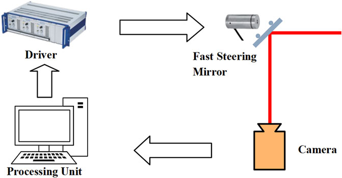
FIGURE 1. High-speed and high-resolution beam stabilization system.
A position-sensitive detector (PSD) [24] was not used to trace the far-field beam spot in the scheme because the spot size and intensity distribution in the spot critically affect detection accuracy. The camera would trace a feature structure in an image, such as a hot spot, rather than trace the entire spot. The control system was developed to study the beam-pointing fluctuation characteristics in the SGII-UP-Petawatt–picosecond system (Figure 2).
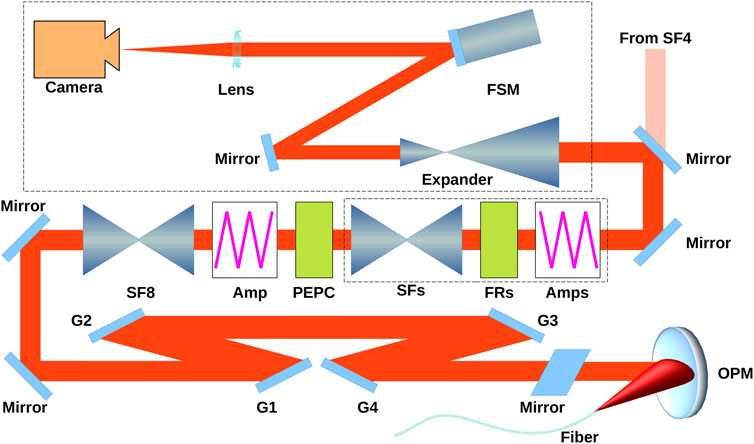
FIGURE 2. Test setup of SGII-UP-Petawatt–picosecond system.
The SGII-UP-Petawatt–picosecond system uses the chirped-pulse amplification (CPA) technique. A short pulse from a mode-locked oscillator is stretched in time using a grating-pulse stretcher and amplified using optical parametric chirped-pulse amplification (OPCPA). The nanosecond pulse is subsequently amplified by the SGII-UP-Petawatt amplification chain. The amplified pulse from spatial filter 4 (SF4) is continuously amplified and transmitted through the spatial filter series SFs (s = 5, 6, 7, 8). The amplified nanosecond pulse is sequentially compressed into a picosecond pulse by the compressor with 4-m gratings (G1–G4). A laser energy of 1 kJ with a pulse width of 2–10 ps is delivered into the target chamber center using an off-axis parabolic mirror (OPM).
In the test, the alignment laser was transmitted backward. A single-mode fiber with NA = 0.12 delivered a CW simulation laser with a wavelength of approximately 1,053 nm, which was the wavelength of the Nd:glass laser system, into the center of the target chamber. The laser was collimated by the OPM and transmitted backward through three transmission mirrors, four gratings, three additional transmission mirrors, SF8, the 35-cm diameter disk amplifiers, and the plasma-electrode Pockels cell (PEPC), followed by a half-wave plate (removed from the beam during system operation) and other spatial filters, amplifiers, and Faraday isolators in sequence. The alignment laser was delivered into the high-speed and high-resolution active beam-pointing stabilization control system. Each isolator in the beam reduced the backward transmission laser power by approximately one-half as the electromagnet was not energized in the test. The high-speed camera was placed on the focal plane. The entire system, from the output end of the fiber to the sensor plane of the high-speed camera, was considered an optical imaging system. The spot on the camera was the image of the output end of the fiber in the chamber. Thus, the position of the spot could be changed according to changes in the tip/tilt of any element in the beam path.
3 Performance of high-speed and high-resolution active beam-pointing stabilization control system
The pointing fluctuations of the laser system were measured for several seconds at 1,000 FPS using the high-speed and high-resolution active beam-pointing stabilization control system. A typical spot distribution is shown in Figure 3.
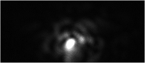
FIGURE 3. Beam far-field distribution on high-speed camera.
The center of the spot indicates the pointing of the system and is processed as follows. First, an area of concern in the frame is chosen to reduce the data size; the spot remains inside this area. The center of the spot is determined using a gravity algorithm automatically executed by the FPGA. The deviation between the current spot position and a reference position is calculated, and a control signal is sent to drive the FSM to point the current spot to the reference position. The relationship between the control voltage applied to the FSM and the pixel deviation is calibrated before the test; when a new frame is obtained, the center of the spot is calculated, and a new control signal is sent out.
Figure 4 shows the details of a recorded segment of beam-pointing fluctuations. The red dotted line represents the horizontal spot deviation referring to the average spot center during a recording period of approximately 4 s; the blue dashed line represents the vertical spot deviation referring to the same reference position. The deviation angle is calculated using the same method. The relationship between the angle and the pixel deviation is calibrated before the test.
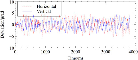
FIGURE 4. Beam-pointing fluctuations of the SGII-UP-Petawatt–picosecond system.
The results showed that the pointing fluctuations from SF4 to the target were approximately 2.8 μrad (RMS) and 6.3 μrad (PV). The frequency spectrum of the beam-pointing fluctuation was analyzed by FFT according to the pointing fluctuations measured (Figure 4), as shown in Figure 5. The analysis indicated that the visible spikes did not exceed 50 Hz, which means that when the active beam-pointing stabilization control system operates above 200 Hz, the pointing fluctuation can be effectively reduced for a 100-m-scale laser system according to the Nyquist sampling law.
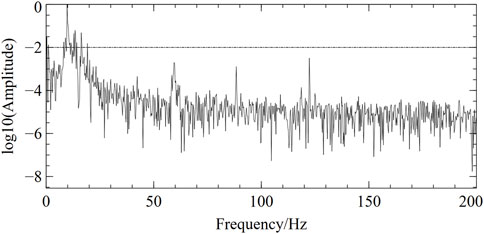
FIGURE 5. Spectrum of beam-pointing fluctuations in the SGII-UP-Petawatt–picosecond system.
The pointing fluctuations are recorded when the active beam-pointing stabilization control system operates in a closed loop, as shown in Figure 6. The pointing fluctuations are significantly reduced in most cases compared with those in Figure 4. The abnormal shocks are likely reduced in the vertical direction (Figure 6A) because the original pointing-fluctuation amplitude was never significantly large; the system operates well at all times in the horizontal direction (Figure 6B). Considering a normal segment of data without spikes for analysis, the pointing fluctuations from SF4 to the target are reduced to 0.63 μrad (RMS) and 1.98 μrad (PV), as shown in Figure 6C.
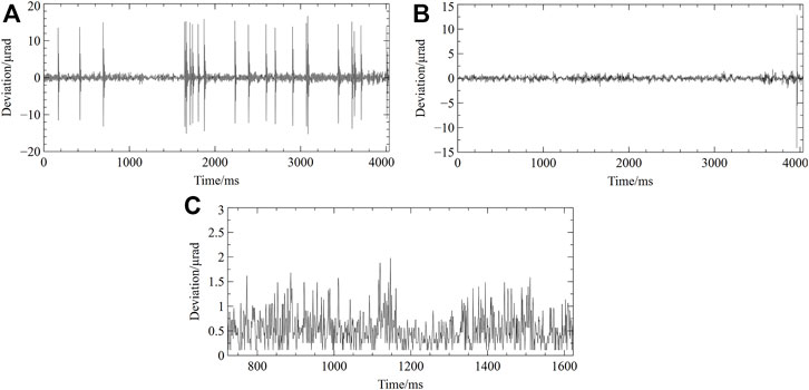
FIGURE 6. Active beam-pointing stabilization control system working in a closed loop in the SGII-UP-Petawatt–picosecond system: (A) Pointing fluctuations in the vertical direction; (B) Pointing fluctuations in the horizontal direction; (C) Pointing fluctuations from 723 ms to 1,624 ms in (A).
This is a challenging task and has never been reported for a high-power laser system. It has been demonstrated in simulations that the tip/tilt error should be no more than 0.5 μrad for two-beam additions to obtain the Strehl ratio (SR) >0.8 [16]. This study meets this requirement in a high-power laser system, paving the way for the application of coherent addition in CPA-configured picosecond–petawatt laser systems.
4 Peak power improvement in multi-beam petawatt laser systems
To evaluate the benefits of this technology, the power of non-coherent addition for eight beams was simulated, considering the pointing fluctuations of the laser system. In the simulation, the far-field distribution of the beam I(i,j) was generated based on the x-ray focal spot grayscale image G (Figure 7), where G(i,j) is the value of the pixel (col = i, row = j). Supposing that the peak power is approximately Imax = 3.4 × 10¹⁸ W/cm2, which is easily attained in a petawatt–picosecond laser system, the distribution I(i,j) can be expressed as follows:
where Gmax is the maximum of the grayscale image G.
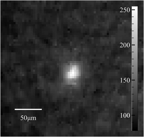
FIGURE 7. X-ray focal spot grayscale image in SGII-UP-Petawatt–picosecond system.
The far-field spot moves from the center of the target corresponding to the pointing fluctuation data; the value of the center for frame k is as follows:
where (xk, yk) denotes the center of frame k (k = 1,2, …, N). The intensity probability distribution p at the center of the chamber can be estimated by the histogram corresponding to Icenter(k), which can be written as follows:
where n = 1,2,3, …, M; M is the number of bins in the histogram; and h(k,n) represents the judgment function for frame k that is used to determine whether the intensity is within the range of n in the histogram.
Supposing that each beam fluctuates independently, the incoherent addition intensity of the eight far-field beams ranges from 0 to 8Imax. The probability of each intensity P is as follows:
where n = 1,2,3, …, 8N, and H(k,n) represents the judgment function for the incoherent addition intensity of eight beams, which is used to determine whether the intensity is within the range of n in the histogram.
Figure 8 shows the probability distribution P(n) of the laser intensity in the center of the target under various pointing-fluctuation conditions. The “open-loop” implies that the pointing-fluctuation data were obtained from non-controlled pointing fluctuations, as shown in Figure 4. The “closed-loop” implies that the active beam-pointing stabilization control system operates as shown in Figures 6A, B. The closed-loop segment indicates that the pointing-fluctuation data are obtained from a segment without abnormal shocks, as shown in Figure 6C. Supposing that the active beam-pointing stabilization control system works in a closed loop for each beam, the certain exceeded intensity (CEXI, “certain” represents >95% probability) is improved from 1.72 × 10¹⁹ W/cm2 to 2.20 × 10¹⁹ W/cm2, as shown in Figure 8B, although occasional high-amplitude pointing fluctuations occurred in the test. Considering the segment without abnormal shocks, the CEXI is further increased to 2.61 × 10¹⁹ W/cm2, which is close to the intensity of the incoherent addition of eight beams (approximately 2.72 × 10¹⁹ W/cm2) without any pointing fluctuation.

FIGURE 8. Performance of an active beam-pointing stabilization control system: (A) Probability distribution of laser intensity at the center of the target; (B) Probability of laser intensity exceeding a certain value.
5 Summary and discussion
This study proposed a high-speed and high-resolution active beam-stabilization system to evaluate pointing-fluctuation characteristics and reduce the pointing fluctuations in high-power laser systems. The maximum frequency of the pointing fluctuations was less than 50 Hz, and the amplitude was approximately 2.8 µrad (RMS) and 6.3 μrad (PV). The active beam-stabilization system was tested on the SGII-UP-Petawatt–picosecond system; the pointing fluctuations were reduced to 0.63 µrad (RMS) and 1.98 μrad (PV). The simulation results for incoherent addition based on the active stabilization system demonstrated that the peak power could be increased by improving the beam stability in the multi-beam picosecond–petawatt laser system. The peak power was improved from 1.72 × 10¹⁹ W/cm2 to 2.61 × 10¹⁹ W/cm2, increased by 51.7%. This technique can also be applied to the coherent addition of laser beams in high-power laser systems.
Given that the active beam-stabilization control scheme was conducted on a laser system in this study, closed-loop control can be improved in the future. The only concern is the application of the stabilization control system when a high-energy shot is launched. A scheme has been proposed for this condition [25, 26], and research is underway. High-precision pointing control in high-power laser systems is expected to be achieved in the near future.
Data availability statement
The original contributions presented in the study are included in the article/Supplementary Material, further inquiries can be directed to the corresponding authors.
Author contributions
ST, YG, and PY contributed to the conception and design of the study. NZ and NH performed the experimental test. XJ analyzed the results. ST wrote the first draft of the manuscript. All authors contributed to the manuscript revision and approved the submitted version.
Funding
This work was supported by the Youth Innovation Promotion Association of the Chinese Academy of Sciences (No. 2019246) and the Strategic Priority Research Program of the Chinese Academy of Sciences (Grant No. XDA25020104).
Conflict of interest
The authors declare that the research was conducted in the absence of any commercial or financial relationships that could be construed as a potential conflict of interest.
Publisher’s note
All claims expressed in this article are solely those of the authors and do not necessarily represent those of their affiliated organizations, or those of the publisher, the editors and the reviewers. Any product that may be evaluated in this article, or claim that may be made by its manufacturer, is not guaranteed or endorsed by the publisher.
References
1. Spaeth M, Manes K, Kalantar D, Miller P, Heebner J, Bliss E, et al. Description of the NIF laser. Fusion Sci Technol (2016) 69(1):25–145. doi:10.13182/fst15-144
2. Haynam C, Sacks R, Wegner P, Bowers M, Dixit S, Erbert G, et al. The National Ignition Facility 2007 laser performance status. J Phys Conf Ser (2008) 112:032004. doi:10.1088/1742-6596/112/3/032004
3. Crane JK, Tietbohl G, Arnold P, Bliss E, Boley C, Britten G, et al. Progress on converting a NIF quad to eight, petawatt beams for advanced radiography. J Phys Conf Ser (2010) 244:032003. doi:10.1088/1742-6596/244/3/032003
4. Di Nicola J, Yang S, Boley C, Crane J, Heebner J, Spinka T., et al. The commissioning of the advanced radiographic capability laser system: Experimental and modeling results at the main laser output. Proc SPIE (2015) 9345:122–33. doi:10.1117/12.2080459
5. Waxer L, Maywar D, Kelly J, Kessler T, Kruschwitz B, Loucks S, et al. High-energy petawatt capability for the omega laser. Opt Photon News (2005) 16(7-8):30–6. doi:10.1364/opn.16.7.000030
6. Denis V, Nicolaizeau M, Neauport J, Lacombe C, Fourtillan P. LMJ 2021 facility status. SPIE (2021) 11666:1166603. doi:10.1117/12.2576671
7. Blanchot N, Behar G, Berthier T, Bignon E, Boubault F, Chappuis C, et al. Overview of PETAL, the multi-Petawatt project on the LIL facility. Plasma Phys Controlled Fusion (2008) 50:124045. doi:10.1088/0741-3335/50/12/124045
8. Danson C, White M, Barr J, Bett T, Blyth P, Bowley D, et al. A history of high-power laser research and development in the United Kingdom. High Power Laser Sci Eng (2021) 9(2):e18. doi:10.1017/hpl.2021.5
9. Danson C, Haefner C, Bromage J, Butcher T, Chanteloup J-CF, Chowdhury E, et al. Petawatt and exawatt class lasers worldwide. High Power Laser Sci Eng (2019) 7(3):e54. doi:10.1017/hpl.2019.36
10. Peng H, Zhang X, Wei X, Zheng W, Jing F, Sui Z, et al. Status of the SG-III solid state laser project. SPIE (1999) 3492:25–33.
11. Zhu J, Zhu J, Li X, Zhu B, Ma W, Lu X, et al. Status and development of high-power laser facilities at the NLHPLP. High Power Laser Sci Eng (2018) 6:e55. doi:10.1017/hpl.2018.46
12. Bromage J, Bahk S-W, Bedzyk M, Begishev I, Bucht S, Dorrer C, et al. MTW-OPAL: A technology development platform for ultra-intense optical parametric chirped-pulse amplification systems. High Power Laser Sci Eng (2021) 9:e63. doi:10.1017/hpl.2021.45
13. Burkhart SC, Bliss E, Di Nicola P, Kalantar D, Lowe-Webb R, Mccarville T, et al. National ignition facility system alignment. Appl Opt (2011) 50(8):1136–57. doi:10.1364/ao.50.001136
14. Gao Y, Cui Y, Li H, Gong L, Lin Q, Liu D, et al. Alignment system for SGII-Up laser facility. Opt Laser Technol (2018) 100(1):87–96. doi:10.1016/j.optlastec.2017.09.049
15. Isono F, Van Tilborg J, Barber S, Natal J, Berger C, Tsai H-E, et al. High-power non-perturbative laser delivery diagnostics at the final focus of 100-TW-class laser pulses. High Power Laser Sci Eng (2021) 9(2):e25. doi:10.1017/hpl.2021.12
16. Gao Y-Q, Ma W-X, Zhu B-Q, Liu D-Z, Cao Z-D, Zhu J, et al. Phase control requirements of high intensity laser beam combining. Appl Opt (2012) 51(15):2941–50. doi:10.1364/ao.51.002941
17. Liu R, Peng C, Liang X, Li R. Coherent beam combination far-field measuring method based on amplitude modulation and deep learning. Chin Opt Lett (2020) 18(4):041402. doi:10.3788/col202018.041402
18. Shaykin A, Kostyukov I, Sergeev A, Khazanov E. Prospects of PEARL 10 and XCELS laser facilities. The Rev Laser Eng (2014) 42:141. doi:10.2184/lsj.42.2_141
19. Chen H, Hermann MR, Kalantar DH, Martinez D, Di Nicola P, Tommasini R, et al. High-energy (>70 keV) x-ray conversion efficiency measurement on the ARC laser at the National Ignition Facility. Phys Plasmas (2017) 24(3):033112. doi:10.1063/1.4978493
20. Tommasini R, Bailey C, Bradley DK, Bowers M, Chen H, Di Nicola J, et al. Short pulse, high resolution, backlighters for point projection high-energy radiography at the National Ignition Facility. Phys Plasmas (2017) 24(5):053104. doi:10.1063/1.4983137
21. Macphee A, Alessi D, Chen H, Cochran G, Hermann M, Kalantar D, et al. Enhanced laser–plasma interactions using non-imaging optical concentrator targets. Optica (2020) 7(2):129–30. doi:10.1364/optica.375486
22. Blanchot N, Marre G, Néauport J, Sibé E, Rouyer C, Montant S, et al. Synthetic aperture compression scheme for a multipetawatt high-energy laser. Appl Opt (2006) 45(23):6013–21. doi:10.1364/ao.45.006013
23. Blanchot N, Bar E, Behar G, Bellet C, Bigourd D, Boubault F, et al. Experimental demonstration of a synthetic aperture compression scheme for multi-Petawatt high-energy lasers. Opt Express (2010) 18(10):10088. doi:10.1364/oe.18.010088
24. Chang H, Ge W-Q, Wang H-C, Yuan H, Fan Z-W Laser beam pointing stabilization control through disturbance classification. Sensors(2021) 21(6):1946. doi:10.3390/s21061946
25. Tang S, Zhu J, Li X, Zhu B, Yang L, Jiang X, et al. China National Intellectual Property Administration, assignee. Light beam drop point position feedback device. CN Patent No 201, 910, 225, 912 (2019).
Keywords: high-power lasers, laser stabilization, coherent addition, incoherent addition, petawatt laser
Citation: Tang S, Guo Y, Yang P, Jiang X, Hua N and Zong N (2023) Stability improvement of multi-beam picosecond–petawatt laser system for ultrahigh peak-power applications. Front. Phys. 11:1118254. doi: 10.3389/fphy.2023.1118254
Received: 07 December 2022; Accepted: 10 January 2023;
Published: 23 January 2023.
Edited by:
Wei-Min Wang, Renmin University of China, ChinaReviewed by:
Zhe Zhang, Institute of Physics (CAS), ChinaMehdi Abedi-Varaki, Center For Physical Sciences And Technology (CPST), Lithuania
Copyright © 2023 Tang, Guo, Yang, Jiang, Hua and Zong. This is an open-access article distributed under the terms of the Creative Commons Attribution License (CC BY). The use, distribution or reproduction in other forums is permitted, provided the original author(s) and the copyright owner(s) are credited and that the original publication in this journal is cited, in accordance with accepted academic practice. No use, distribution or reproduction is permitted which does not comply with these terms.
*Correspondence: Yajing Guo, gracegg@siom.ac.cn; Pengqian Yang, yangpengqian@siom.ac.cn