Coincidence time resolution of radiation detector based on 6×6 mm2 ToF SiPM detectors with different readout schemes
 Changyu Li1
  Kun Hu
- 1Key Laboratory of Particle Physics and Particle Irradiation (MOE), Institute of Frontier and interdisciplinary Science, Shandong University, Qingdao, Shandong, China
- 2Anhui Specreation Instrument Technology Co., Ltd., Hefei, Anhui, China
- 3School of Electrical and Electronic Engineering, Wuhan Polytechnic University, Wuhan, China
Introduction: Nowadays, attention is growing on the Silicon Photomultipliers (SiPMs) detector for many applications, especially in nuclear medicine. In Positron Emission Tomography (PET) scanner, timing performance of a PET detector plays a significant role in image reconstruction.
Methods: This work mainly aims at the processing of timing signal for the purpose of achieving a good timing performance. We applied a timing detector made up of a 3 × 3 × 10 mm3 LYSO crystal directly coupled with a large-size SensL SiPM with a sensitive area of 6 × 6 mm2. The standard output of the SiPM was used for energy calculation while the fast output was for timing pickoff. Three different readout configurations for fast timing signals were used for timing performance evaluation: 1) the recommended RF transformer-based readout, 2) the cascaded Common Emitter Amplifier (CEA), 3) the commercial RF amplifier.
Results: Experiment results show that the best FWHM CTR values for the three were 228.3 ± 1.4 ps, 235.4 ± 1.1 ps and 231.1 ± 1.5 ps for the RF transformer-based, the CEA-based and the RF amplifier-based readout configurations respectively. The schemes based on the CEA-based and the RF amplifier-based configurations have a good uniformity at different trigger thresholds.
Discussion: For practical application, the amplified timing signal based on the CEA circuit is more desirable because it is more feasible for trigger threshold selection in multichannel readout electronics system.
1 Introduction
In recent years, Silicon Photomultiplier (SiPM) had been increasingly used in many research fields such as nuclear medicine [1–5]. Time-of-Flight (ToF) performance is a very important factor to improve the image quality in Positron Emission Tomography (PET) reconstruction. Excellent timing resolution enables direct annihilation photons localization using ToF information without tomographic reconstruction [6]. Recent studies in timing resolution are mainly about fast scintillators and Cerenkov emitting materials by using low-noise readout electronics [7, 8]. In the development of ToF-PET scanners, timing resolution of the PET detector is still being improved [9–11]. At present, the best Coincidence Timing Resolution (CTR) is about 30 ps Full Width at Half Maximum (FWHM) when utilizing a Cerenkov detector coupled with a Microchannel Plate Photomultiplier (MCP-PMT) [12]. In high energy physics, the ToF performance also dominates particle identifications in the spectrometer. In the BESIII, the plastic scintillators serve as the ToF system [13]. In the AMS-100 proposal, a ToF system is constructed with small scintillator rods read out by SiPM arrays at both ends. The proposed ToF system have achieved a time resolution of 50 ps for particle mass reconstructions [14].
For practical application, it is very challenging to enable the ToF capability of SiPM arrays or strip SiPMs that comprise so many detection channels. For signal processing of the SiPM array, one approach is to use multiplexing network circuit, which consists of resistor-based [15] and capacitor-based [16] schemes. The number of readout electronics channels can be reduced in these schemes. However, contributions of extra RC constant in these schemes will lower rise time of the SiPM signals, thus degrading the ToF performance. For readout electronics of the SiPM detectors, Time-Over-Threshold (TOT) is a commonly used method [17]. In the TOT method, the timing information can be uniquely determined by measuring the leading edge of the SiPM signals. Due to non-linearity between the deposited energy and the digital pulse, it needs additional corrections in this method. Another approach is to apply compact Application-Specific Integrated Circuit (ASIC) design. Compared with regular electronics readout schemes based on discrete components, the ASIC designs are able to maximize ToF capability such as NINO ASIC [18], HRFlexToT [19].
In nuclear medicine, the small-size SiPMs, such as those with 3 × 3 mm2 and 2 × 2 mm2 active area, have been well studied [20–22]. In high energy physics, however, the large-size SiPMs, such as 6 × 6 mm2, are more desirable, such as Super Tau-Charm Facility (STCF) [23] to be constructed in China. In this paper, the timing performance of radiation detector based on large size SiPM is evaluated. The evaluation is mainly focused on SiPMs with fast output terminal. For the purpose of practical application, two kinds of amplification circuits were designed to amplify the fast timing signal.
2 Materials
In the evaluation of timing performance, two identical one-to-one coupling detectors were mounted. Each one had a LYSO crystal bar with a size of 3 × 3 × 10 mm3 and a SensL J-series SiPM [24] evaluation board (MicroFJ−SMTPA−60,035) [25]. The evaluation board provided a standard output for energy and a fast output for timing pickoff. The crystal was wrapped with Teflon (PTEE) tapes except for the exit face and coupled to the SiPM window by use of silicon grease. For the signal observation, an adapter board was designed and assembled under the evaluation board. The detectors were mechanically fixed using a designed 3-D printed holder. The SiPM has an active area of 6.07 × 6.07 mm2 with 35
3 Methods
This work mainly focuses on readout method for best timing performance. The fast output of the SensL J-series SiPM has a sharp leading edge, giving rise to a better timing performance compared with the standard output. The evaluation setups described in the following sections have been applied for timing pickoff.
3.1 RF transformer based output
The CTR measurement setup is illustrated in Figure 1. In this system, the timing pickoff was based on the reference readout circuit. The RF-transformer was applied to decrease the impact of the parasitic and passive capacitances of the SiPM detector, which facilitated the extraction of the fast signal components [26, 27]. The adapter board was designed to directly connect the fast output signal to a 50 Ω terminated oscilloscope for signal observation. The fast output from the SiPM was used for timing pickoff. The standard output for the SiPM was also sent to the oscilloscope with a 50 Ω termination, which was for energy calculation. The oscilloscope features a bandwidth of 1 GHz and a sampling rate of 5 GS/s. In the experiment, a Na-22 point source was applied to irradiate the two detectors. In the oscilloscope, a logic trigger mode was applied. In the logic trigger, four waveforms including two energy signals and two timing signals were simultaneously recoded once when both of the energy signals passed the thresholds. Note that the timing signals were not used for event trigger because of their small amplitudes. The trigger thresholds for both energy signals were identical. The bias voltages for both SiPMs ranged from 27 V to 32 V, and the trigger thresholds were 50 mV, 100 mV, 150 mV, 200 mV, 250 mV and 300 mV respectively. For each bias voltage, we collected 20,000 events.
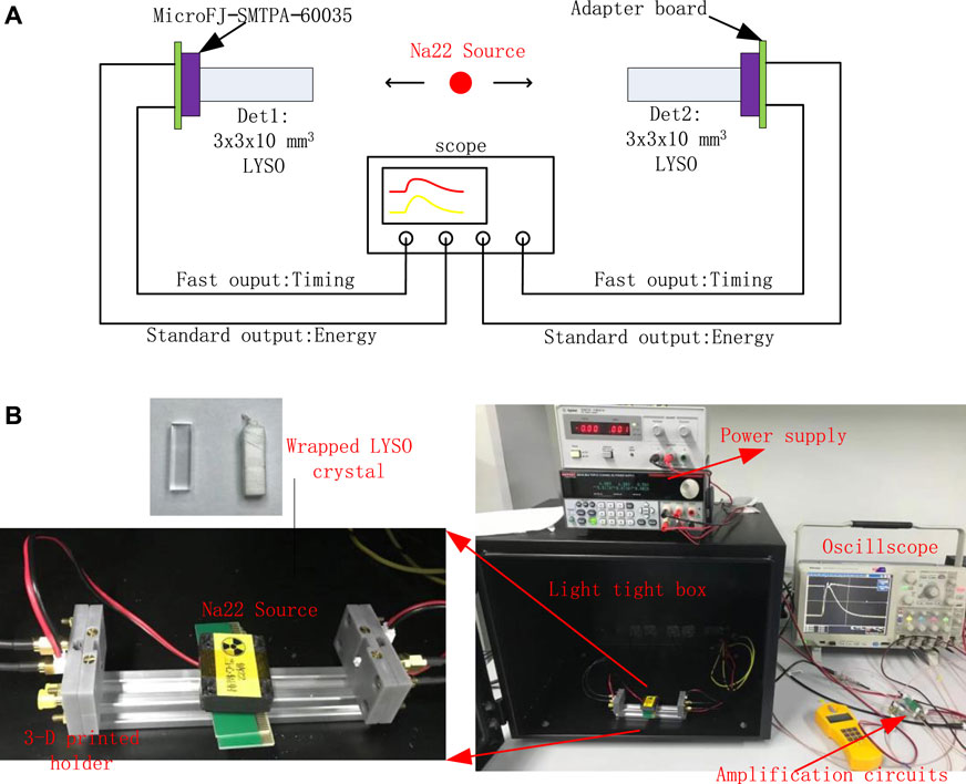
FIGURE 1. Experimental setup (A) and photograph (B) for timing evaluation.
3.2 Readout circuit based on common-emitter amplifier
Considering that the fast output has a small output capacitance of 160 pF [24], it will result in a very fast leading edge. However, the amplitude of the timing signal from a gamma event is less than 15 mV. In practical application, it is not suitable for the timing pickoff. In second readout scheme, the timing signal was amplified by a two-stage amplification circuit. The circuit consisted of two common-emitter amplifiers generated by discrete components, as illustrated in Figure 2. A low noise silicon bipolar RF transistor (BFR106, Infineon) with a maximum 5 GHz frequency was applied to create the CEA circuit. R1 and R2 were used to provide a bias for the transistor, establishing a proper operating Q-point. A bypass capacitor C2 was to enhance the AC gain at high frequency. R3 was for thermal stability by negative feedback. The gain of the CEA was determined by R4. In between, the two CEAs were coupled with a 100 nF capacitor. The fast output of the SiPM was directly fed to input of the CEA circuit with a 50 Ω termination. The output of two-stage CEA circuit was directly sent to the oscilloscope with a 50 Ω termination. Overall, the gain of the two-stage CEA circuit was about 70.
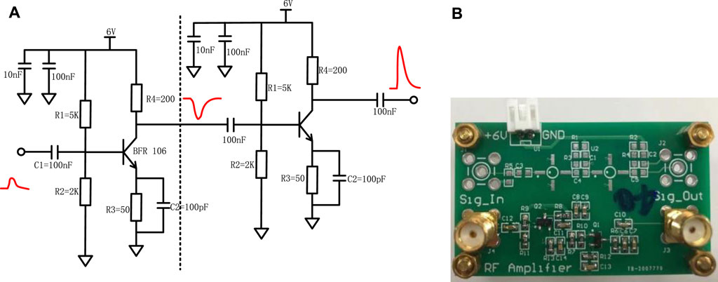
FIGURE 2. Schematic (A) and photograph (B) of two-stage common-emitter amplification circuit.
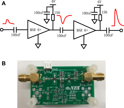
FIGURE 3. Schematic (A) and photograph (B) of two-stage amplification circuit based on minicircuit RF amplifier.
3.3 Readout circuit based on RF amplifier
The last readout scheme is similar with the CEA. The timing signal was amplified by two high speed Minicircuits MAR-6+ RF amplifiers, as illustrated in Figure 3. Both amplifiers were cascaded for signal amplification before timing pickoff. The commercial amplifier was a wideband amplifier offering high dynamic range from DC to 2 GHz。The cascaded structure provided a very high gain for small signals. The RF amplifier needed an external bias resistor. In our experimental setup, the resistor was 150 Ω. After measurements, the overall gain of the two-stage RF amplification circuit was about 60.
3.4 Signal processing
Figure 4 shows a typical example of the acquired waveforms by the oscilloscope, including the energy and timing signals of the two detectors (Det1 and Det2). Here we show the timing signal output based on the RF amplifier. The waveforms on the oscilloscope were sent to a PC via USB interface and recorded via MATLAB software with TekVISA driver. Totally, three kinds of experiments based on RF-transformer, CEA circuit and RF amplifier were carried out. For each experiment, totally 20,000 events were recorded.
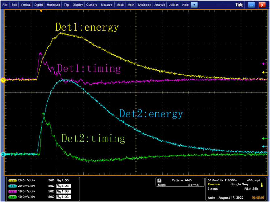
FIGURE 4. Typical waveforms of a coincidence event captured by the oscilloscope.
With the recorded waveforms, we firstly made the baseline correction, that was, subtracting the mean baseline value at first 200 sample point. The energy was the integration of all data point from energy signals. In the meantime, we used the timing signal to determine the CTR. Picking off the leading edge of the timing waveform, we performed a cubic spline interpolation at the rising edge of the timing signals in 10 ps step. In order to obtain a better timing performance, different trigger thresholds from 1 mV to 10 mV in 1 mV step were used. For each threshold, we acquired a histogram showing the distribution of time difference between Det1 and Det2 signals for all back-to-back photon events. Additionally, a 400–600 keV energy window was applied to each detector to select 511 keV gamma photons. In the timing distribution, we directly applied the FWHM of the histogram to represent the CTR.
4 Results
The timing signal waveforms of the three readout schemes are shown in Figure 5. The recommended readout based on RF transformer resulted in very small signals. The signals can be amplified by the commercial RF amplifiers. For the CEA-based schemes, the waveform was a little distorted. However, it ensured the high gain in high frequency. Therefore, the optimum timing can be picked off.
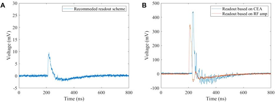
FIGURE 5. Typical timing waveforms in three experiments based on transformer-based readout (A), CEA-based readout and RF amplifier-based readout (B) schemes.
Figure 6 shows energy spectra for Det1 and Det2 respectively. For the energy resolution calculations, a referenced Cs-137 point source was applied to irradiate the two detectors. Compared with the energy spectrum irradiated by the Cs-137 source, the evaluated energy resolutions were 9.41% and 9.38% for the two detectors respectively.
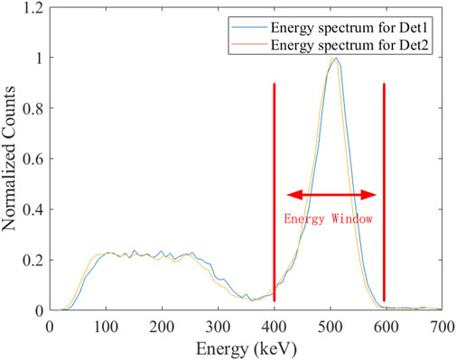
FIGURE 6. Typical energy spectra for Det1 and Det2 respectively.
Figure 7 shows the CTR distributions when scanning the trigger threshold at different bias voltages. Under each bias voltage, it should be noted that the CTR degrades with the increased thresholds. From these timing distributions, one biased at 32 V showed best timing performance. These experiments are repeated three times. The CTR value of both coincidence detectors was given by the mean ± standard deviation of the three measurements. The best CTR value at 32 V based on the RF transformer-based scheme was 228.3 ± 1.4 ps. Figure 8 shows a typical CTR spectrum at 2 mV trigger threshold when biased at 32 V.
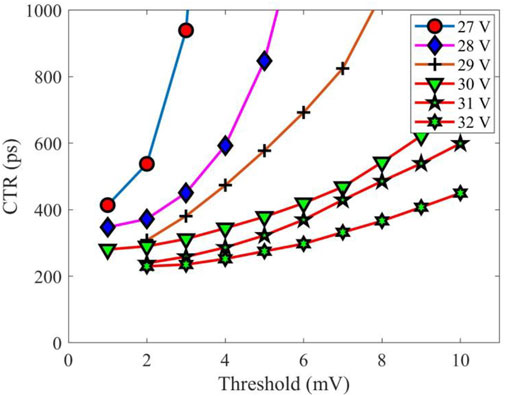
FIGURE 7. FWHM CTR results by scanning trigger thresholds when the SiPMs are biased at different voltages.
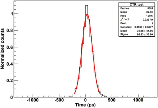
FIGURE 8. The CTR spectrum at 2 mV threshold based on the RF transformer-based scheme.
Since the best timing result was obtained when biased at 32 V, the following experiments based on the CEA-based and RF amplifier-based readout were also carried out at 32 V. Figure 9 was a plot of the CTR results when scanning different trigger thresholds. The CTR distribution for the CEA-based readout scheme was relatively uniform. The best FWHM CTR values were 235.4 ± 1.1 ps at 24 mV threshold for the CEA-based readout and 231.1 ± 1.5 ps at 14 mV threshold for the RF amplifier-based readout, respectively. Figure 10 shows typical CTR spectra for both readout schemes.
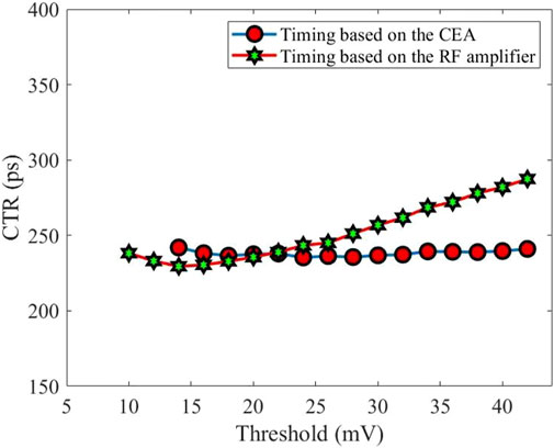
FIGURE 9. CTR distributions at different trigger thresholds based on CEA-based and RF amplifier-based readout schemes.
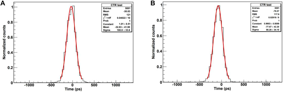
FIGURE 10. Best CTR spectra based on CEA-based (A) and RF amplifier-based (B) readout schemes.
4 Discussions
In this work, we have evaluated and compared the CTR values of three different timing readout schemes for two 3 × 3 × 10 mm3 LYSO crystals coupled with a 6 × 6 mm2 SiPM detector respectively. The timing readout configurations were based on RF transformer-based, CEA-based and RF amplifier-based circuits respectively. From our measurements, the optimum timing can be obtained at 32 V bias voltage. Scanning the trigger thresholds, the best FWHM CTR values were 228.3 ± 1.4 ps, 235.4 ± 1.1 ps and 231.1 ± 1.5 ps for the RF transformer-based, the CEA-based and RF amplifier-based readout respectively. Although we can obtain a good CTR performance under the RF transformer-based readout, it is not practical for multi-channel, high-density readout electronics system where one can not set 1 mV trigger threshold because it is very sensitive to the noise level. The best way is to amplify the timing signals. From our studies, the amplified timing signal retained the fast leading edge in the CEA-based and RF amplifier-based schemes. In comparison, the CTR distribution in the CEA-based scheme is more uniform than that in the RF amplifier-based scheme. In practical multi-channel readout electronics system, it is better to set a unified trigger threshold under the condition of the optimum timing performance.
In the three readout schemes, the RF transformer is a passive component. The power consumption for the RF transformer-based circuit can be negligible. In normal operation, a 6-V power supply (223A-30-3, Tektronix) was applied on the CEA-based and RF amplifier-based circuits. 18 mA and 16 mA current were observed for the CEA-based and RF amplifier-based circuits respectively. Although the power consumptions were a little large, the number of timing channels is generally far less than that of the signal readout electronics. It is acceptable for practical SiPM-based detector system. One needs to make a trade-off when choosing the number of the timing signals in whole readout system.
There have four factors that affect the total timing performance in the experiment in terms of intrinsic timing performance of the instrumentation, scintillation statistics of the scintillator, SiPM technology itself and signal readout method. Firstly, from the perspective of the instrumentation, the oscilloscope we used had a bandwidth of 1 GHz and a sampling rate of 5 GS/s. Splitting the fast output of the SiPM into two identical signals, the intrinsic timing performance of the oscilloscope was measured, as shown in Figure 11. The intrinsic CTR value was 116.0 ps. Deconvolving the contribution of intrinsic timing performance of the instrumentation to the CTR, the best FWHM CTR value for the RF transformer-based readout method became 196.6 ps, which was a little better than the results in [28] where it showed a 203 ps CTR value when two 3 × 3 × 20 mm3 LYSO crystals were coupled with 3 × 3 mm2 SiPMs. Although many ToF measurement experiments with multiplexed SiPM [29–32] had proven the importance of reducing capacitance in the readout electronics path, and the output capacitance (160 pF) of the 6 × 6 mm2 SiPM at fast output end is four times larger than that (40 pF) of the 3 × 3 mm2 SiPM, the contribution to rise time of SiPM output signal should be negligible because the sense resistor RS of the 6 × 6 mm2 SiPM is five times smaller than that of the 3 × 3 mm2 SiPM.
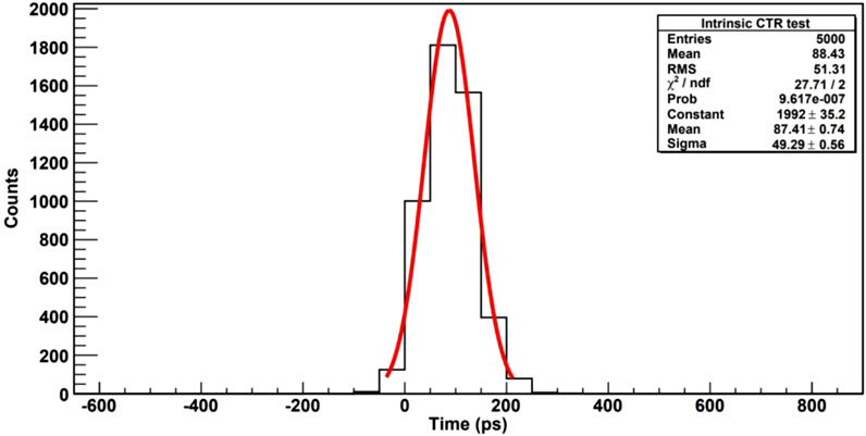
FIGURE 11. Intrinsic CTR spectrum of the oscilloscope.
From the perspective of scintillation statistics in the crystal, the CTR is related to the scintillation decay time (τd), the scintillation rise time (τr) and the number of detected photons n), i.e.
From the perspective of SiPM technology itself, the novel Near Ultraviolet (NUV) SiPM from FBK provides a lower-afterpulse (Low-AP) substrate and a lower electric field (Low-F) feature in comparison with the SiPMs from Hamamatsu and SensL. The low-AP substrate can achieve an improvement of the CTR of about 30 ps [39]. Coupling a 3 × 3 × 5 m3 LYSO crystal to a 4 × 4 m2 NUV SiPM, an excellent CTR value of 130 ps can be reached.
Last but not least, from the perspective of the readout method, the time resolution in the electronics path can be given by
For future work, we plan to glue ESRs outside the LYSO crystal except for the exit face. It can raise the number of scintillation lights that the SiPMs receive. It should contribute to the leading edge of the timing signals. In addition, we will construct a ToF PET detector including a SiPM array and a LYSO array. Multiple 6 × 6 mm2 SiPMs will be designed to form the SiPM array, which is used to read out the 2 × 2 mm2 LYSO array. The LYSO array consists of many 2 × 2 × 10 mm3 LYSO bars. The LYSO array is directly 9-to-1 coupled with the SiPM array. Consequently, we will further improve the CTR performance of the ToF PET detectors constructed with 6 × 6 mm2 SiPM. The other experiment is for detector verification of the STCF experiment [41]. In the STCF, plastic scintillators work as ToF detectors. We plan to apply 6 × 6 mm2 SiPM to study the timing performance of the scintillation detector with a dual-end readout.
5 Conclusion
In summary, we evaluated the timing performance of both detectors based on large-size SiPMs using three different readout circuit. The best CTR value can be obtained at 32 V bias voltage when using RF transformer-based readout scheme for timing signal processing. The CTR distribution for the CEA-based readout scheme was relatively uniform. For practical application, the amplified timing signal based on the CEA circuit is more desirable because it is more feasible for trigger threshold selection in multi-channel readout electronics system.
Data availability statement
The original contributions presented in the study are included in the article/Supplementary Material, further inquiries can be directed to the corresponding authors.
Author contributions
KH: Conceptualization, methodology, writing, supervision. CL: Software, visualization, validation. YL: Data curation, investigation. JX: Investigation, resources, visualization. SX: Conceptualization, methodology, writing, supervision.
Funding
This work was supported by the Natural Science Foundation of Shandong Province (No. ZR2022QA039) and the Program of Qilu Young Scholars of Shandong University.
Conflict of interest
JX was employed by Anhui Specreation Instrument Technology Co., Ltd.
The remaining authors declare that the research was conducted in the absence of any commercial or financial relationships that could be construed as a potential conflict of interest.
Publisher’s note
All claims expressed in this article are solely those of the authors and do not necessarily represent those of their affiliated organizations, or those of the publisher, the editors and the reviewers. Any product that may be evaluated in this article, or claim that may be made by its manufacturer, is not guaranteed or endorsed by the publisher.
References
1. Buzhan P, Dolgoshein B, Filatov L, Ilyin A, Kaplin V, Karakash A, et al. Large area silicon photomultipliers: Performance and applications. Nucl Instr Meth A (2016) 567(1):78–82. doi:10.1016/j.nima.2006.05.072
2. Wu Y, Catana C, Farrel R, Dkhale PA, Shah KS, Qi J, et al. PET performance evaluation of an MR-compatible PET insert. IEEE Trans Nucl Sci (2009) 56(3):574–80. doi:10.1109/TNS.2009.2015448
3. Surti S. Update on time-of-flight PET imaging. J Nucl Med (2015) 56(1):98–105. doi:10.2967/jnumed.114.145029
4. Vanderberghe S, Mikhaylova E, Dhoe E, Mollet P, Karp JS. Recent developments in time-of-flight PET. EJNMMI Phys (2016) 3:3. doi:10.1186/s40658-016-0138-3
5. Schaart DR, Schramm G, Nuyte J, Surti S. Time of flight in perspective: Instrumental and computational aspects of time resolution in positron emission tomography. IEEE Trans Radiat Plasma Med Sci (2021) 5(5):598–618. doi:10.1109/TRPMS.2021.3084539
6. Kwon SI, Ota R, Berg E, Hashimoto F, Nakajima K, Ogawa I, et al. Ultrafast timing enables reconstruction-free positron emission imaging. Nat Photon (2021) 15:914–8. doi:10.1038/s41566-021-00871-2
7. Cates JW, Gundacker S, Auffray E, Lecoq P, Levin CS. Improved single photon time resolution for analog SiPMs with front end readout that reduces influence of electronic noise. Phys Med Biol (2018) 63:185022. doi:10.1088/1361-6560/aadbcd
8. Gundacker S, Turtos RM, Auffray E, Paganoni M, Lecoq P. High-frequency SiPM readout advances measured coincidence time resolution limits in TOF-PET. Phys Med Biol (2019) 64:055012. doi:10.1088/1361-6560/aafd52
9. Cates JW, Levin CS. Electronics method to advance the coincidence time resolution with bismuth germanate. Phys Med Biol (2019) 64(17):175016. doi:10.1088/1361-6560/ab31e3
10. Ota R, Nakajima K, Hasegawa T, Ogawa I, Tamagawa Y. Timing-performance evaluation of Cherenkov-based radiation detectors. Nucl Instr Meth A (2019) 923:1–4. doi:10.1016/j.nima.2019.01.034
11. Tao L, He Y, Kanatzidis MG, Levin CS. Study of annihilation photon pair coincidence time resolution using prompt photon emissions in new perovskite bulk crystals. IEEE Trans Radiat Plasma Med Sci (2022) 6(7):804–10. doi:10.1109/TRPMS.2022.3149992
12. Ota R, Nakajima K, Ogawa I, Tamagawa Y, Shimoi H, Suyama M, et al. Coincidence time resolution of 30 ps FWHM using a pair of Cherenkov-radiator-integrated MCP-PMTs. Phys Med Biol (2019) 64(7):07LT01. doi:10.1088/1361-6560/ab0fce
13.BES Collaboration. The construction of the BESSIII experiment. Nucl Instr Meth A (2009) 598(1):7–11. doi:10.1016/j.nima.2008.08.072
14. Kirn T. The AMS-100 experiment: The next generation magnetic spectrometer in space. Nucl Instr Meth A (2022) 1040:167215. doi:10.1016/j.nima.2022.167215
15. Wang Z, Sun X, Lou K, Meier J, Zhou R, Yang C, et al. Design, development and evaluation of a resistor-based multiplexing circuit for a 20×20 SiPM array. Nucl Instr Meth A (2016) 816:40–6. doi:10.1016/j.nima.2016.01.081
16. Du J, Schmall JP, Yang Y, Di K, Dokhale PA, Shah KS, et al. A simple capacitive charge-division readout for position-sensitive solid-state photomultiplier arrays. IEEE Trans Nucl Sci (2013) 60(5):3188–97. doi:10.1109/TNS.2013.2275012
17. Jung J, Choi Y, Kim KB, Lee S, Choe H. An improved time over threshold method using bipolar signals. Phys Med Biol (2018) 63(13):135002. doi:10.1088/1361-6560/aacab4
18. Pourashraf S, Montoro AG, Lee MS, Cates JW, Won JY, Zhao Z, et al. Investigation of analog and digital signal processing chains of a prototype TOF PET system with 100 ps coincidence time resolution. In: Proc. IEEE Conf. Nucl. Sci. Symp. Rec.; 31 October 2020 - 07 November 2020; Boston MA USA (2021). p. 1–3. doi:10.1109/NSS/MIC42677.2020.9508016
19. Sanchez D, Gomez S, Mauricio J, Freixas L, Sanuy A, Guixe G, et al. HRFlexToT: A high dynamic range ASIC for time-of-flight positron emission tomography. IEEE Trans Radiat Plasma Med Sci (2022) 6(1):51–67. doi:10.1109/TRPMS.2021.3066426
20. Raylman R, Stolin A, Majewski S, Proffitt J. A large area, silicon photomultiplier-based PET detector module. Nucl Instr Meth A (2014) 735:602–9. doi:10.1016/j.nima.2013.10.008
21. Niu M, Liu Z, Kuang Z, Wang X, Ren N, Sang Z, et al. Ultra-high-resolution depth-encoding small animal PET detectors: Using GAGG and LYSO crystal arrays. Med Phys (2022) 49(5):3006–20. doi:10.1002/mp.15606
22. Yang Q, Kuang Z, Sang Z, Yang Y, Du J. Performance comparison of two signal multiplexing readouts for SiPM-based pet detector. Phys Med Biol (2019) 64:23NT02. doi:10.1088/1361-6560/ab5738
23. Fang Z, Liu Y, Shi H, Liu J, Shao M. A hybrid muon detector design with RPC and plastic scintillator for the experiment at the Super Tau-Charm Facility. JINST (2021) 16:P09022. doi:10.1088/1748-0221/16/09/P09022
24.Onsemi. Semiconductor components industries, LLC (2017). Available at: https://www.onsemi.com/pdf/datasheet/microj-series-d.pdf (Accessed August, 2021).
25.Onsemi. Semiconductor components industries, LLC (2015). Available at: https://www.onsemi.com/pub/Collateral/AND9808-D.PDF (Accessed September, 2018).
26. Wang M, Wang Y, Cao Q, Wang L, Kuang J, Xiao Y. Comparison of three pre-amplifier circuit for time readout of SiPM in TOF-PET detector. In: 2019 IEEE International Symposium on Circuits and Systems (ISCAS); 26-29 May 2019; Sapporo, Japan (2019). p. 1–5. doi:10.1109/ISCAS.2019.8702411
27. Acerbi F, Gundacker S. Understanding and simulating SiPMs. Nucl Instr Meth A (2019) 926:16–35. doi:10.1016/j.nima.2018.11.118
28. Won JY, Lee JS. Highly integrated FPGA-only signal digitization method using single-ended memory interface input receivers for time-of-flight PET detectors. IEEE Trans Biomed Circ Sys (2018) 12(6):1401–9. doi:10.1109/TBCAS.2018.2865581
29. Bieniosek MF, Cates JW, Levin CS. Achieving fast timing performance with multiplexed SiPMs. Phys Med Biol (2016) 61:2879–92. doi:10.1088/0031-9155/61/7/2879
30. Du J, Peng P, Bai X, Cherry SR. Shared-photodetector readout to improve the sensitivity of positron emission tomography. Phys Med Biol (2018) 63:205002. doi:10.1088/1361-6560/aae056
31. Park H, Lee JS. Highly multiplexed SiPM signal readout for brain-dedicated TOF-DOI PET detectors. Phys Med (2019) 68:117–23. doi:10.1016/j.ejmp.2019.11.016
32. Park H, Yi M, Lee JS. Silicon photomultiplier signal readout and multiplexing techniques for positron emission tomography: A review. Biomed Eng Lett (2022) 12:263–83. doi:10.1007/s13534-022-00234-y
33. Seifert S, Dam HT, Vinke R, Dendooven P, Lohner H, Beekman FJ, et al. A comprehensive model to predict the timing resolution of SiPM-based scintillation detectors: Theory and experimental validation. IEEE Trans Nucl Sci (2012) 59(1):190–204. doi:10.1109/TNS.2011.2179314
34. Derenzo SE, Choong WS, Moses WW. Fundamental limits of scintillation detector timing precision. Phys Med Biol (2014) 59(13):3261–86. doi:10.1088/0031-9155/59/13/3261
35. Gundacker S, Auffray E, Frisch B, Jarron P, Knapitsch A, Meyer T, et al. Time of flight positron emission tomography towards 100ps resolution with L(Y)SO: An experimental and theoretical analysis. J Instrumentation (2013) 8:P07014. doi:10.1088/1748-0221/8/07/P07014
36. Kang HG, Yamaya T, Han YB, Song SH, Ko GB, Lee JS, et al. Crystal surface and reflector optimization for the SiPM-based dual-ended readout TOF-DOI PET detector. Biomed Phys Eng Express (2020) 6:065028. doi:10.1088/2057-1976/abc45a
37. Yeom JY, Vinke R, Levin CS. Side readout of long scintillation crystal elements with digital SiPM for TOF-DOI PET. Med Phys (2014) 41(12):122501. doi:10.1118/1.4901524
38. Lee MS, Cates JW, Montoro AG, Levin CS. High-resolution time-of-flight PET detector with 100ps coincidence time resolution using a side-coupled phoswich configuration. Phys Med Biol (2021) 66:125007. doi:10.1088/1361-6560/ac01b5
39. Ferri A, Acerbi F, Gola A, Paternoster G, Piemonte C, Zorzi N. Performance of FBK low-afterpulse NUV silicon photomultipliers for PET application. JINST (2016) 11:P03023. doi:10.1088/1748-0221/11/03/P03023
40. Vasilescu G. Electronic noise and interfering signals. 1st ed. Heidelberg, Germany: Springer-Verlag (2005).
Keywords: TOF performance, PET, SiPM, LYSO, amplifier
Citation: Li C, Li Y, Xi J, Xiang S and Hu K (2023) Coincidence time resolution of radiation detector based on 6×6 mm2 ToF SiPM detectors with different readout schemes. Front. Phys. 11:1050234. doi: 10.3389/fphy.2023.1050234
Received: 21 September 2022; Accepted: 19 January 2023;
Published: 30 January 2023.
Edited by:
Qian Sen, Institute of High Energy Physics (CAS), ChinaReviewed by:
Andrea Gonzalez-Montoro, Polytechnic University of Valencia, SpainFabio Acerbi, Bruno Kessler Foundation (FBK), Italy
Copyright © 2023 Li, Li, Xi, Xiang and Hu. This is an open-access article distributed under the terms of the Creative Commons Attribution License (CC BY). The use, distribution or reproduction in other forums is permitted, provided the original author(s) and the copyright owner(s) are credited and that the original publication in this journal is cited, in accordance with accepted academic practice. No use, distribution or reproduction is permitted which does not comply with these terms.
*Correspondence: Shitao Xiang, 22113009@whpu.edu.cn; Kun Hu, kun.hu@sdu.edu.cn