Experiment and Application Study on High-Performance Grouting Material Used to Solve the Floor Heave Problem of Broken Soft Rocks
 Jie Xu1,2
  Jingdong Jiang3*
- 1Geotechnical Research Institute, Hohai University, Nanjing, China
- 2Key Laboratory of Ministry of Education for Geomechanics and Embankment Engineering, Hohai University, Nanjing, China
- 3Nanjing Hydraulic Research Institute, Nanjing, China
To meet the project demands of controlling the floor heaves in broken soft rocks, a new high-performance grouting material was studied. The main performance parameters of the grouting materials with different ratios, such as the setting time, the density and bleeding ratio, the viscosity, and fluidity, were investigated in the laboratory tests. The results indicated that the optimal additive ratio is 6‰. The unconfined compression strength tests and conventional triaxial compression tests were carried out on the common and reinforced mudstones, which indicate that the strengthened effect of the new grouting materials is significant. The new high-performance grouting material was applied to controlling the floor heaves of the broken soft rocks in the coal mine. The numerical simulation and filed monitoring results indicate that the new grouting material can effectively improve the strength of soft rock and control the floor heaves.
Introduction
More and more deep soft rock roadways are under construction with the increase in mining depth. The soft rock roadways have the characteristics of soft surrounding rock, low strength, and low stability, which have brought great difficulty to the development and maintenance of the roadways [1–3]. Rib spalling, roof fall, and floor heaves due to soft rock swelling occur frequently, which extremely impair the safety in coal mine production. Therefore, to explore an effective approach and technique to improve the surrounding rock structure is the key problem to be solved in soft rock roadway support [4–6].
Floor heave is a kind of large deformation failure, which also occurs in the deep soft rock roadways, results in great money loss, and greatly affects the safety production [7, 8]. Many scholars have studied floor heaves based on different methods such as laboratory tests, in situ monitoring, and numerical simulation [9–15]. Zhong et al. [16] investigated the occurrence mechanism and influencing factors of the floor heaves for soft rock tunnels by means of field investigations and geologic surveys, which provide a theoretical basis for the forecast of the floor heave. To solve the problem of stability control in soft rock roadways, Chang et al. [17] revealed the mechanism of floor heaves and designed reasonable support parameters of hydraulic expansion bolts. The results showed that the hydraulic expansion bolts can reduce the plastic zone in the floor.
In the 1940s, grouting materials were widely used in engineering. In the 1960s, organic polymer materials developed rapidly, and chemical grouting materials such as urea-formaldehyde resin, lignin, and acrylamide were successfully developed. Since the 1970s, grouting materials such as ultra-fine cement slurry and cement water–glass C-S slurry have been widely used because of their low pollution and excellent performance [18, 19]. Appropriate cement grouting is an effective floor reinforcement technique that can control excessive floor heaves. Injecting cement grout into roadway floors can provide a more uniform reinforcement throughout the floor. So far, the grouting reinforcement technique has been widely used in roadway support. The grouting material is a key factor affecting the grouting effect. Thus, many scholars have carried out considerable research works on grouting materials [20–25]. Shimada et al. [26] studied the reinforcement effect of cement grouting materials with different water–cement ratios on the floor. Sun et al. [27] carried out tests to manufacture a new anti-swelling grouting material. The results show that the optimal ratio of the additive is 5‰ when the water–cement ratio is 0.5: 1, and the grouting material can enhance the strength of the broken and swelling soft rock. To study the influence of grouting reinforcement on the mechanical properties of rock mass fractures, an innovative method for making rock mass fracture specimens is proposed by our team, which overcomes the difficulty of the original rock fracture sampling. The grouting reinforcement test was carried out on the self-developed fractured rock mass grouting system platform, and the normal and tangential mechanical loading tests were performed on the rock mass fracture specimens after grouting reinforcement [28, 29].
In this study, a new high-performance grouting material has been found. The main performance parameters of the grouting materials with different ratios were investigated in the laboratory tests. The unconfined compression strength tests and conventional triaxial compression tests were carried out on the common and reinforced mudstones, which indicate that the strengthened effect of the new grouting materials is significant. The numerical simulation and filed monitoring results indicate that the new grouting material can effectively control the floor heaves.
Materials and Methods
Experimental Materials
The main components of the experimental materials are superfine cement and active mineral composite additives, and the cement mainly consists of CaO (49.36%), SiO2 (29.12%), Al2O2 (10.08%), Fe2O3 (6.03%), and MgO (5.41%).
Performance Parameters of Cement Grout With Different Proportions
For the broken soft surrounding rocks, the water–cement ratio of the cement grout is usually set as 1:1, 0.9:1, 0.7:1, 0.6:1, and 0.5:1, and thus the intermediate ratio of 0.7:1 is chosen in this study. The function of the active mineral composite additive is to reduce the viscosity and increase the fluidity. The additives were added into the cement grout with the increase in mass percent by 3‰. It was found that the viscosity and fluidity of the cement grout had no obvious changes when the mass percent of the additive reached 9‰, and thus, the performance tests of the cement grout were carried out with the additive ratio of 0‰, 3‰, 6‰, and 9‰.
Setting Time of Cement Grout
The initial setting and final setting times of the cement grout with different proportions were measured using the standard Vicat apparatus. The cement paste was mixed according to the ratio, filled in the mold, and then cured in the moisture curing box. The first test was performed after 30 min. When the needing test moved down to the position of about 4 ± 1 mm away from the bottom board, the cement grout entered the initial setting state, and the time from the cement addition to the initial setting state is the initial setting time. Then the mold was rotated 180° and cured again in the moisture curing box. When the depth of the needing test insertion sample is 0.5 mm, the cement entered the final setting state, and the time from the cement addition to the final setting state is the final setting time.
Density and Bleeding Ratio of Cement Grout
The bleeding ratio is used to describe the volume of the residual cement grout after stewing. The prepared cement and additive are added to the water, and fully stirred using the cement paste mixer. Then the mixture is put into the measuring cylinder, the quantity and volume are measured, and then the density of the cement grout is calculated. The grout is maintained for 2 h, the volume of the underlayer grout is read, and the bleeding ratio is calculated. When the additive ratio is less than or equal to 6‰, the density of the grout materials decreases with the additive ratio increasing. As the additive ratio continues to increase, the density shows little change. It was found that the bleeding ratio with 6‰ additive ratio was lower than those with other additive ratios.
Viscosity and Fluidity of Cement Grout
The viscosity of the cement grout is measured using the funnel viscometer. First, the cement paste is poured into the viscometer through the mesh screen, whose outlet is stanched with hand. Then a 500-ml measuring cup is put under the outlet of the funnel, and the outlet is opened. At the same time, the stopwatch is started and the flow time of the grout is signed until the 500-ml measuring cup is filled up with the grout materials. The fluidity of the cement grout is measured through the fluidity test mold. First, the fluidity test mold is placed in the middle of the test board, which is smooth, clean, and waterless. Then, the fluidity test mold is filled with the prepared grout materials, and moved on up 5–10 cm in 2 s, holding the position for 10–15 s to let the materials flow smoothly. After 4 min, the diameters of two vertical directions are measured and the average is taken, which is the fluidity of the cement grout. It was found that the viscosity of the grout materials decreases and the fluidity increases with the additive ratio increasing.
Optimal Ratio
The lower grouting pressure is usually adopted in the soft rock roadway. This requires the grout materials to have a lower viscosity and a higher fluidity, to ensure the o expansion of the infiltration radius of the grout materials. To reduce water swelling, the grout materials should have a lower bleeding ratio. Through comprehensive consideration of the physical and mechanical properties of the grout materials, the optimal additive ratio is 6‰.
Mechanical Characteristics of Grouting Reinforced Mudstone
The unconfined compression strength tests and conventional triaxial compression tests were carried out on the common and reinforced mudstones, respectively, in a RMT-301 servo-controlled rock mechanics experimental system. The mechanical parameters of common mudstone and the solid for seven and 14 days are listed in Table 1.
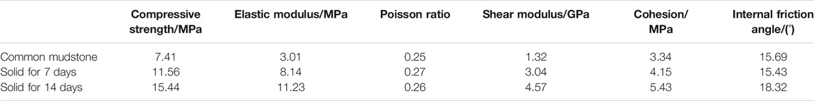
TABLE 1. Mechanical parameters of mudstone and solid.
Compared with the mudstone samples, the unconfined compressive strength of the solid for 14 days increased by 108.4%, the elastic modulus increased by 273.1%, the shear modulus increased by 246.2%, and the cohesion increased by 62.3%. Compared with the solid for 7 days, the unconfined compressive strength of the solid for 14 days increased by 33.6%, the elastic modulus increased by 37.9%, the shear modulus increased by 50.3%, and the cohesion increased by 30.8%. It was found that the mechanical parameters of the solid for 7 days have reached 70% of those for 14 days, which indicate that the strengthened effect of the grouting materials is significant.
Results
Engineering Application
The tape machine roadway located in the south wing of the Gubei coal mine is the main coal haulage system of the south wing. The maximum horizontal principal stress is 19.65 MPa, and the direction is 335°, which strikes obliquely to the roadway. The lateral pressure coefficient reaches an average of 1.11, and thus, the roadways are under a higher environment of geo-stress. According to the long-term on-site monitoring, the surrounding rock of the roadway is very unstable, and the floor and two sides may lose stability. The floor heave is a serious issue and threatens the stability of the adhesive tape machine and the coal haulage system.
Model Foundation
The engineering geological model of the tape machine roadway is built by UDEC based on appropriate simplification. The geometry of the model is 70 m
Numerical Simulation Results
Stress redistribution would occur due to the excavation disturbance, and the plastic zone forms in the surrounding rock of the roadways. Figures 1–3 show the simulated results of different schemes. In Scheme I, the range of stress concentration around the roadway is relatively large, and a large shear plastic zone appears after excavation. The local block (the so-called key block) slips, forming a failure zone dominated by tension failure. The deformation at the bottom of the roadway is large. In Scheme II, because of the application of grouting reinforcement measures at the side arch, the degree of stress concentration and the area are significantly reduced. Because of the combined support of multiple means, the floor heave is greatly reduced and tends to be stable, and there are only long shear and tensile plastic zones in the bottom plate. The new grouting materials used in Scheme II have better reinforcement performance, which can effectively improve the strength of soft rock and control the floor heaves.
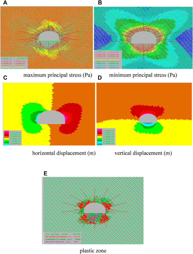
FIGURE 1. Simulated results of Scheme I.
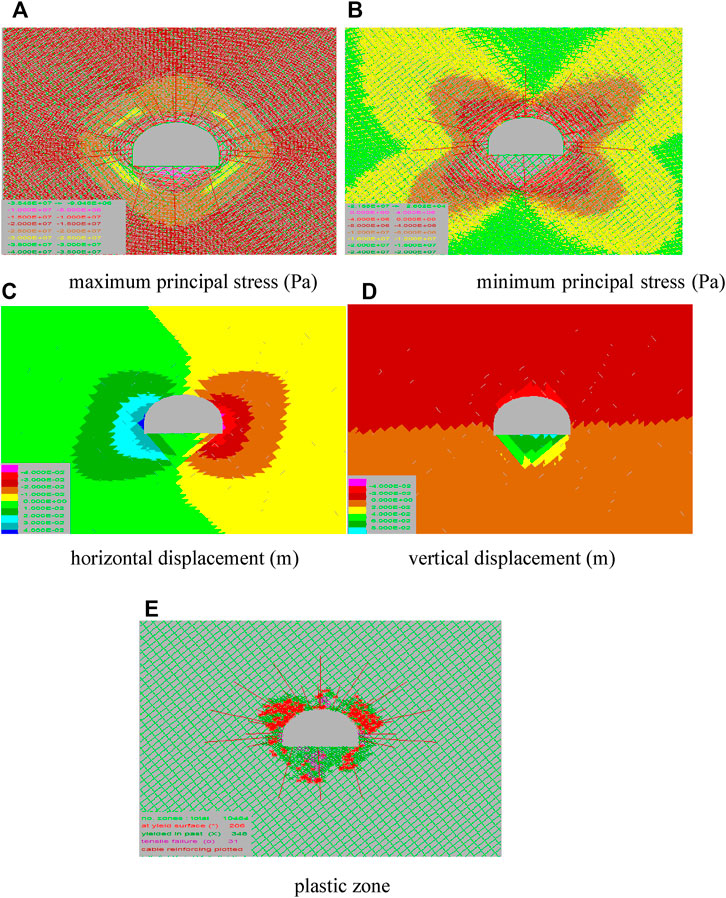
FIGURE 2. Simulated results of Scheme II.
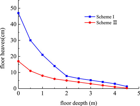
FIGURE 3. Floor heaves of different schemes.
Field Monitoring Results
The new high-performance grouting materials were used in managing the floor-heave problem in the tape machine roadway. Monitoring work shows that the floor heave rate reduces to 0.05 mm/d about one month after treatment, and the floor gradually reaches a steady state.
According to the monitoring results of the side deformation, the stability of the two sides after grouting has been significantly improved, and the deformation rate has been reduced from 10 mm/d to 0.5 mm/d. All the aforementioned results indicate that the new grouting materials can effectively control the floor heaves in the soft rock roadway.
Discussion
The action mechanism of the grouting material proposed by us is reflected in the consolidation and enhancement of surrounding rock fissures. After grouting, the surrounding rock fissures are bonded, which improves the integrity of the surrounding rock and the shear strength and stiffness of the fissures. After the grout is filled into the fracture, a new network skeleton structure is formed, which makes the deformation modulus of the fractured rock mass increase significantly; after the fracture is filled, the stress concentration at the end of the fracture is greatly weakened or even disappears, changing the original fracture expansion and failure mechanism, and curbing the rheological deformation of the surrounding rock. The widely used cement-based inorganic grouting material is too brittle (the strain before the peak is less than 1%, and the stress is vertical drop type after the peak), the fracture surface of the surrounding rock undergoes a slight shear and tension deformation, and the grouting stone body will fail. Although resin-based organic grouting materials can meet the requirements of strength and deformation properties, they are too expensive to be used in large quantities. The grouting material proposed by us is an economical and practical one. The numerical simulation results and filed monitoring results indicate that the new high-performance grouting material can effectively improve the strength of soft rock and control the floor heaves.
Data Availability Statement
The original contributions presented in the study are included in the article/Supplementary Materials; further inquiries can be directed to the corresponding author.
Author Contributions
JX designed and conducted the experiments. JJ carried out the numerical simulation and field investigation. JX and JJ complied and analyzed the output data, and finished the first version of the manuscript. All authors edited and approved the final version of the manuscript.
Funding
This work was supported by the Fundamental Research Funds for the Center Universities (Grant No. 2019B04914), and the National Natural Science Foundation of China (Grant No. 51808191).
Conflict of Interest
The authors declare that the research was conducted in the absence of any commercial or financial relationships that could be construed as a potential conflict of interest.
Publisher’s Note
All claims expressed in this article are solely those of the authors and do not necessarily represent those of their affiliated organizations, or those of the publisher, the editors, and the reviewers. Any product that may be evaluated in this article, or claim that may be made by its manufacturer, is not guaranteed or endorsed by the publisher.
References
1. Jiao Y-Y, Song L, Wang X-Z, Coffi Adoko A. Improvement of the U-Shaped Steel Sets for Supporting the Roadways in Loose Thick Coal Seam. Int J Rock Mech Mining Sci (2013) 60:19–25. doi:10.1016/j.ijrmms.2012.12.038
2. Kang Y, Liu Q, Gong G, Wang H. Application of a Combined Support System to the Weak Floor Reinforcement in Deep Underground Coal Mine. Int J Rock Mech Min Sci (2014) 142–50. doi:10.1016/j.ijrmms.2014.03.017
3. Guo Z, Shi J, Wang J, Cai F, Wang F. Double-directional Control Bolt Support Technology and Engineering Application at Large Span Y-type Intersections in Deep Coal Mines. Mining Sci Techn (China) (2010) 20:254–9. doi:10.1016/s1674-5264(09)60193-9
4. Yao QL, Li B, Ren SJ, Li XH. Application of Hollow Grouted Anchor cable in Soft Coal Roadway under High in- Situ Stress. J Min Satety Eng (2011) 198.
5. Kontogianni V, Stiros S. Induced Deformation during Tunnel Excavation: Evidence from Geodetic Monitoring. Eng Geol (2005) 79(1-2):115–26. doi:10.1016/j.enggeo.2004.10.012
6. Zhang XY, Gu JC, Shen J, Chen AM. Research on Anchored Effect of Fully Cement Imbedded Anchor cable on Weak Country Rock Cavern. Rock Soil Mech (2006) 27(2):294. doi:10.16285/j.rsm.2006.02.026
7. Sun XM, Zhang GF, Cai F. Asymmetric Deformation Mechanism within Inclined Rock Strata Induced by Excavation in Deep Roadway and its Controlling Countermeasure. Chin J Rock Mech Eng (2009) 28(6):1137.
8. Sun X-m., Chen F, He M-c., Gong W-l., Xu H-c., Lu H. Physical Modeling of Floor Heave for the Deep-Buried Roadway Excavated in Ten Degree Inclined Strata Using Infrared thermal Imaging Technology. Tunnelling Underground Space Techn (2017) 63:228–43. doi:10.1016/j.tust.2016.12.018
9. Jing HH, Hu G, He X. Study on Numerical Simulations for Mechanism of the Floor Heave in Inclined Stratum Roadway. Min Area Press Roof Control (2001) 1:14–6.
10. Zhu WS, Li Y, Li SC, Wang SG. Quasi-three-dimensional Physical Model Tests on a Cavern Complex under High In-Situ Stresses. Int J Rock Mech Min Sci (2011) 48(2):199–209.
11. Zhao Y, Liu N, Zheng X, Zhang N. Mechanical Model for Controlling Floor Heave in Deep Roadways with U-Shaped Steel Closed Support. Int J Mining Sci Techn (2015) 25(5):713–20. doi:10.1016/j.ijmst.2015.07.003
12. Xu Y, Chen J, Bai J. Control of Floor Heaves with Steel Pile in Gob-Side Entry Retaining. Int J Mining Sci Techn (2016) 26:527–34. doi:10.1016/j.ijmst.2016.02.024
13. Li SC, Wang Q, Wang HT, Jiang B, Wang DC, Zhang B, et al. Model Test Study on Surrounding Rock Deformation and Failure Mechanisms of Deep Roadways with Thick Top Coal. Tunnelling Underground Space Techn (2015) 47:52–63. doi:10.1016/j.tust.2014.12.013
14. Jeon S, Kim J, Seo Y, Hong C. Effect of a Fault and Weak Plane on the Stability of a Tunnel in Rock-A Scaled Model Test and Numerical Analysis. Int J Rock Mech Mining Sci (2004) 41(Suppl. 1):658–63. doi:10.1016/j.ijrmms.2004.03.115
15. Tang SB, Tang CA. Numerical Studies on Tunnel Floor Heave in Swelling Ground under Humid Conditions. Int J Rock Mech Min Sci (2012) 55:137–50. doi:10.1016/j.ijrmms.2012.07.007
16. Zhong ZL, Tu XR, Liu XR. Occurrence Mechanism and Control Technology of the Floor Heave Disaster for Soft-Rock Tunnel. Dis Adv (2012) 5(4):987.
17. Chang Q, Zhou H, Xie Z, Shen S. Anchoring Mechanism and Application of Hydraulic Expansion Bolts Used in Soft Rock Roadway Floor Heave Control. Int J Mining Sci Techn (2013) 23(3):323–8. doi:10.1016/j.ijmst.2013.05.017
18. Soler JM, Vuorio M, Hautojärvi A. Reactive Transport Modeling of the Interaction between Water and a Cementitious Grout in a Fractured Rock. Application to ONKALO (Finland). Appl Geochem (2011) 26(7):1115–29. doi:10.1016/j.apgeochem.2011.04.001
19. Yin J-H, Zhou W-H. Influence of Grouting Pressure and Overburden Stress on the Interface Resistance of a Soil Nail. J Geotech Geoenviron Eng (2009) 135(9):1198–208. doi:10.1061/(asce)gt.1943-5606.0000045
20. Koga M, Sasaoka T, Shimada H, Kubota S, Matsui K. Numerical Simulation on Grouting Materials Injection into Soil. Proceedings of 29th International Symposium on Computer Applications in the Minerals Industries. Beijing: China (2001). p. 627–30.
21. Ito Y, Sakaguchi T, Nishiyama K, Fujiwara A. On Grouting Test Using a Suspension of Ultrafine clay on Artificially Cracked Rock Samples. Doboku Gakkai Ronbunshu (1996) 1996:231–42. doi:10.2208/jscej.1996.547_231
22. Koga M, Shimada H, Matsui K. Study on Injection Experiment to Simulated Ground of Grout Materials and Applicability of Injection Analysis Which Introduced Filtration Theory. Study on Infiltration Behavior of Grout Materials in Grouting. 2nd Report. Shigen-to-Sozai (2002) 118(1):29–35. doi:10.2473/shigentosozai.118.29
23. Sasaoka T, Shimada H, Kubota S, Fundamental Study for Simulation of Grouting in Soil/fracture Rock Mass Using Eulerian-Lagragian Seepage Analysis, Proceedings of ’99 Japan-Korea Joint Symposium on Rock Engineering. Fukuoka: Japan (1999). p. 483–8.
24. Liu RT, Li SC, Zhang QS, Yuan XS, Han W, Experiment and Application Research a New Type of Dynamic Water Grouting Material. Chin J Rock Mech Eng (2011) 30(7):1454
25. Li LP, Li SC, Zhang QS, Cui JS, Xu ZH, Li Z, Experimental Study of a New Polymer Grouting Material. Chin J Rock Mech Eng (2011) 29(Suppl. 1):3150.
26. Shimada H, Hamanaka A, Sasaoka T, Matsui K. Behaviour of Grouting Material Used for Floor Reinforcement in Underground Mines. Int J Mining, Reclamation Environ (2014) 28(2):133–48. doi:10.1080/17480930.2013.804257
27. Sun XM, Chen F, Liang GF, Fu Y, Guo ZB, Wu ZQ, Experimental and Application Research on Grouting Materials for Preventing Swelling of Soft Rock. Chin J Rock Mech Eng (2017) 36(2):457–65.
28. Liu QS, Lei GF, Lu CB, Peng XX, Zhang J, Wang JT, Experimental Study of Grouting Reinforcement Influence on Mechanical Properties of Rock Fracture. Chin J Rock Mech Eng (2017) 36(S1):3140–7.
Keywords: high performance, grouting material, floor heave, broken soft rock, optimal additive
Citation: Xu J and Jiang J (2022) Experiment and Application Study on High-Performance Grouting Material Used to Solve the Floor Heave Problem of Broken Soft Rocks. Front. Phys. 10:829681. doi: 10.3389/fphy.2022.829681
Received: 06 December 2021; Accepted: 14 February 2022;
Published: 10 March 2022.
Edited by:
Wanqing Shen, Université de Lille, FranceReviewed by:
Gurpal Singh, Panjab University, IndiaShiyue Zhang, Shanghai Research Institute of Materials (SRIM), China
Copyright © 2022 Xu and Jiang. This is an open-access article distributed under the terms of the Creative Commons Attribution License (CC BY). The use, distribution or reproduction in other forums is permitted, provided the original author(s) and the copyright owner(s) are credited and that the original publication in this journal is cited, in accordance with accepted academic practice. No use, distribution or reproduction is permitted which does not comply with these terms.
*Correspondence: Jingdong Jiang, 704793796@qq.com