A reflective metasurface for broadband OAM vortex wave generation
 Meng Zhang1 Desen Li2 Jiahan Lin2 Bingzhi Zhang2 Jifang Tao3 Zhenxue Zhao4 Yuan Zeng4 Wenli Shang1*
  Wu Zhang2*
- 1School of Electronics and Communication Engineering, Guangzhou University, Guangzhou, China
- 2School of Physics and Material Science, Guangzhou University, Guangzhou, China
- 3School of Information Science and Engineering, Shandong University, Qingdao, China
- 4Guangzhou Quality Supervision and Testing Institute, Guangzhou, China
In this paper, we proposed a reflective metasurface which controls the phase delay of the electromagnetic (EM) wave through geometric phase manipulation. By coding the metasurface unit cells in different orientation angles, an orbital angular momentum (OAM) wave can be obtained through the metasurface reflection. A broadband reflective OAM wave with mode l = −1 was demonstrated which was experimentally observed from 8.3 GHz to 11.6 GHz. The mode spectrum of OAM wave was analyzed and the spectrum weight was about 0.82 through numerical calculation and about 0.47 through experimental measurement for the mode l = −1. The realization of this broadband OAM wave has the potential application to improve the OAM wave based communication capacity.
Introduction
With the rapid development of wireless communication technology, the fifth or sixth generation of mobile communication has been highly desired, which leads to the increasing shortage of wireless spectrum resources. While traditional approaches, such as time division multiplexing, frequency division multiplexing, spatial division multiplexing and other technologies are difficult to increase the utilization of spectrum resources, how to further improve communication system capacity has attracted the researchers focus in recent years. As the essential element of the communication system, electromagnetic (EM) wave carries not only radiation energy but also linear and angular momentum. The angular momentum can be further subdivided into spin angular momentum (SAM) and orbital angular momentum (OAM). As early as 1909, Poynting theoretically predicted the existence of angular momentum for circularly polarized light [1]. In 1936, Beth derived that a polarized light moment applied on a birefringence plate can change its polarization state, and experimentally verified [2] that there would be a SAM for circularly polarized light. In 1989, Coullet et al. observed a phenomenon similar to superfluid vortex in laser cavities with large Fresnel numbers, and raise the optical vortex concept [3]. Until 1992, Allen et al. found the existence of OAM in Laguerre–Gaussian (LG) beam, and proposed the definition of OAM, indicating that there is an independent azimuthal factor exp (−ilφ) for the amplitude of the LG beam, where l is the topological charge or the azimuthal mode number, and φ is the azimuthal angle [4]. The wavefront phase of the vortex electromagnetic wave shows a spiral distribution. Theoretically, the OAM can take any value to represent the vortex wave mode at any frequency. Different modes of vortex wave are mutually orthogonal and do not interfere, which therefore realizes a new physical degree of freedom to improve the wireless communication capacity.
With the exploration of vortex electromagnetic wave in the wireless communication system, it has become a research hotspot to efficiently generate vortex electromagnetic wave research in recent years. Traditionally, the generation of vortex electromagnetic waves are mainly through spiral phase plate (SPP), antenna or antenna array. SPP was proposed in early years to generate orbital angular momentum [5,6]. In 1996, Turnbull et al. successfully demonstrate the OAM wave through the SPP working in the millimeter-wave frequency band [7]. In 2012, Mahmouli et al. generated OAM beams at 60 GHz frequencies using SPPs and were successfully applied to the signal transmission [8]. A single antenna is relatively simple to design, and the vortex phase can be obtained by radiating out the helical phase. However, the vortex electromagnetic wave obtained by this method often has small gain, narrow bandwidth and large divergence angle, which is not easy to transmit [9–12]. The antenna array arranges an array of traditional antennas to directly generate the vortex electromagnetic beam through a well designed feeding system [13–16]. The system specifies different radiation phases to each radiation element to achieve desired OAM mode. In 2015, Mari et al. implemented vortex electromagnetic waves with OAM of l = 1 using a parabolic antenna, which works at 17.2 GHz and verified its near-field performance [9]. In 2020, Cui and Feng utilized spoof surface plasmon polaritons (SSPP) to realize vortex waves with different SSPP modes at different frequencies, and experimentally verified their near and far field characteristics [10,11]. The antennas or antenna array successfully realize the OAM beam, however, the size of the antennas is relatively large and with a high cost. Meanwhile, the research of vortex electromagnetic wave based on circular antenna array is also carried out. In 2014, Bai et al. designed a circular phased antenna array that produces five modes of OAM radio beams at 10 GHz from a metal patch and a feed network [13]. In 2017, Deng et al. used the same principle to generate a vortex electromagnetic wave [15] with eight OAM modes near 1.9 GHz.
In 2011, Yu et al. first designed the metasurface consisting of the V-shaped structure and proposed the design principle of the metasurface. Later he successfully realized the vortex beam in the optical frequency band, which provided a simple and effective way to use the metasurface to manipulate electromagnetic waves [17]. Compared with the SPP, antenna or antenna array introduced above, the metasurfaces have the advantages of low thickness, simple design and low cost, which are favored by researchers. Generally, there are two methods to generate vortex electromagnetic waves based on metasurfaces, namely structure parameter transformation method and geometric phase method. The former one obtains the desired vortex electromagnetic wave wavefront phase by changing the structure parameters or shape of the metasurface unit, which is applicable to generate a linear polarizing vortex wave. The latter method obtains the spiral wavefront phase of the vortex electromagnetic wave by rotating the central axis of the metasurface cell structure, which is applicable to generate a circularly polarized vortex wave.
Based on the structural parameter method, the researchers have achieved fruitful results [18–21]. In 2016, Yu et al. designed a vortex metasurface using a three-oscillator antenna to realize the vortex electromagnetic wave [22] at the 5.8 GHz frequency. Later, Wang et al. proposed a concept of smooth dispersion metasurface, and realized the working bandwidth of the vortex wave metasurface broadening [23] through the bow structure. In 2019, Huang et al. used the double ring structure to design the vortex metasurface, which works under both x polarization and y polarization electromagnetic waves, providing a possibility the vortex wave polarization multiplexing communication [24] In the same time, Akram et al designed broadband vortex metasurfaces to improve the purity of OAM, and experimentally verified the theory of [25]. The research of generating the vortex electromagnetic wave based on the geometric phase method is also being carried out. The unit cell of the metasurface is rotated at different angles, and the phase obtained after the rotation is twice the rotation angle, so the phase of the vortex wave can be obtained without changing the structural parameters. In addition, all the rotating unit structures, with the same dispersion characteristics, can generate vortex electromagnetic waves with broadband characteristics. In 2017, Xu et al. used double-layer orthogonal polymetallic strips as the metasurface unit cell to achieve the broadband vortex electromagnetic wave [26]. The metasurface is polarization-insensitive, but the divergence angle of the vortex waves is divergent and detrimental to propagation. In 2018 and 2019, Ran et al. and Wang He et al. introduced the focused phase into the vortex metasurface design, which successfully realized the focused vortex beam [27,28] by using the two-arrow structure and the Z-type unit structure design, respectively. In a summary, metasurfaces can realize the OAM beam at low cost with small sized designs, and are able to control the OAM beam much more flexibly. However, above work usually demonstrated the OAM beam at only a single frequency. To improve the utilization of the OAM in the communication field, in this paper, we designed a reflective metasurface consisting of new Z-shaped unit cells and realized a broadband OAM beam.
Data and methods
The designed metasurface for the OAM beam generation consists of unit cells with a Z-shaped metallic structure on the top of a substrate as shown in Figure 1A. A metal layer is covered at the backside of the substrate which couples with the Z-shape structure, the side view of which is depicted in Figure 1B. Two short arms are designed at the two ends of the Z-shape to provide more flexible control on the amplitude and phase delay of the reflective beam by optimizing the dimensions of the two arms. The final designed size of the unit cell is labeled in Figure 1A. The arm length and height of the Z-shaped structure are 3.25 and 4.00 mm, the length of the short arms on the two ends of the Z-shaped structure is 4.00 mm, and the width of the shape is 1.5 mm. The lattice constant of unit cell is 12 × 12 mm. The phase control of the unit cell on the incident EM wave is based on the geometric phase principle, which induces a phase delay of the EM wave depending on the geometric orientation angle of the unit cell. The metasurface is modelled using Microwave Studio of Computer Simulation Technology (CST) in periodic boundary condition. The substrate of the metasurface is made of FR4 with permittivity of 4.3 and thickness of 1.6 mm. The Z-shaped structure and the metal layer at the backside of the substrate are made of copper with conductance of 5.8 × 10⁷ S/m. A left circularly polarized plane wave is normally incident on the metasurface and the cross-polarized reflective spectrum of the EM wave are numerically analyzed from 4 GHz to 18 GHz range. Figures 1C,D plot the simulated amplitude and the phase delay of the reflective spectrum at different unit cell orientation angle θ. As θ changes from 0° to 157.5° with step size of 22.5°, the cross polarized reflective amplitude R keeps almost the same at different θ in the investigated frequency range, while the phase delay changes linearly with θ and the change can be up to 360° as θ increases by 180°. Therefore, it is possible to control the wave front reflective EM beam by simply setting the rotated angle of the unit cell at a specific spatial position.
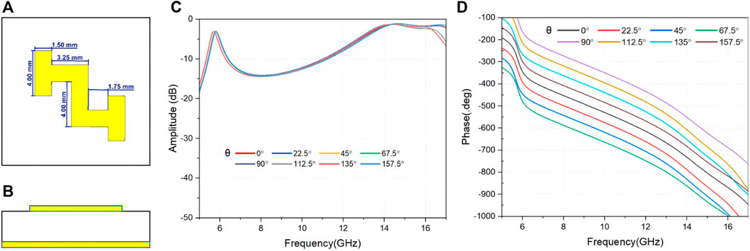
FIGURE 1. (A) The top view and (B) the side view of the designed unit cell; (C) the reflective amplitude and (D) the phase delay of the unit cell at different oriented angles.
To generate a reflective vortex beam, the unit cells are patterned so that the phase delay at each unit cell spatial position increases linearly with the position’s azimuth angle, and finally increases by integer times of 360° when the azimuth angle increases by 180°. Here we demonstrated a vortex beam with mode l = −1, so the phase delay change increases by 360° in one circle around of the center of the metasurface. Due to the discontinuous of the design, we coded the unit cells with 8 rotated orientation into 3-bit code from 000 to 111. The cross circularly-polarized phase delay of different coded unit cell at different frequency is list in Table 1 in the Supplementary Material. It can be seen that the phased delay variation from 8 to 12 GHz is within 2° for the same rotated orientation, which indicates that the coding is valid for a broadband frequency range. The whole metasurface for the vortex beam generation contains 12 × 14 unit cell array and therefore is about 4.8λ × 5.6λ for the center frequency of 10 GHz as shown in Figure 2A. The array is divided into 8 triangle regions, in which the unit cells are patterned in the order of the coding as shown in Figures 2A,B. In each triangle region there are 21 identical unit cells. The numbers of unit cells on the lines from the center to the edge of the metasurface in each triangle region are 1, 2, 3, 4, 5 and 6. Based on this design, the metasurface is fabricated using printed circuit board (PCB) technology. The Z-shaped unit cells are patterned on the top of the PCB as shown in Figure 2C and the metal layer is on the backside of the PCB.
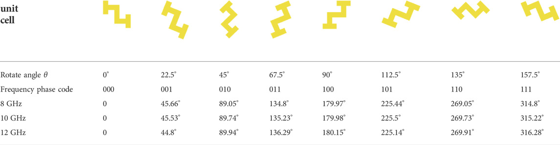
TABLE 1. Cross polarized phase delay of different coded unit cell at different frequency.
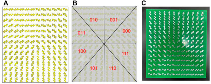
FIGURE 2. (A) The illustration of unit cell array pattern and (B) the coding arrangement of the metasurface; (C) the fabricated metasurface on the PCB.
Results and discussion
The phase distribution of the reflected field is then modeled in the CST Microwave studio in the open boundary condition. A left-circularly polarized plane wave is incident on the metasurface, electrical field distribution of the reflective right-circularly polarized OAM beam on a transverse plane 200 mm above the reflective metasurface is calculated at the frequency of 8 GHz, 10 GHz and 12 GHz. The reflected wave shows a null energy at the center and a donut energy distribution around the center as shown in Figures 3A–C for the above three frequencies, respectively. The corresponding phase distributions were calculated Figures 3D–F, which are in helical shape distribution and demonstrate the OAM beam with mode l = −1 at these frequencies. The OAM spectrum of the reflective beam is then calculated by applying Fourier transforms to the electrical field distributions through the Equation (1)
where Al is the weight of the lth mode of the OAM beam.
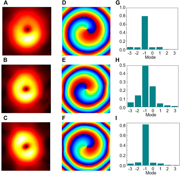
FIGURE 3. (A–C) The amplitude distribution and (D–F) the phase delay distribution and (G–I) the OAM spectrum of the simulated reflect wave at 8 GHz, 10 GHz and 12 GHz, respectively.
The electrical field of the reflective wave was measured in an anechoic chamber with a vector network analyzer (VNA, Keysight N5225A) and a field scan system as illustrated in Figure 4A. An horn antenna was connected to the VNA and feeds the metasurface, and the electrical field on the transverse plane in front of the metasurface was scanned using an electrical probe as shown in Figure 4B. The metasurface holder is placed 2 m from the horn antenna and the electrical probe is 300 mm from the metasurface holder. The scanned transverse plane range is 400 mm × 400 mm with 26 × 26 pixels. The horn antenna feeds a linearly polarized wave, and the electrical field
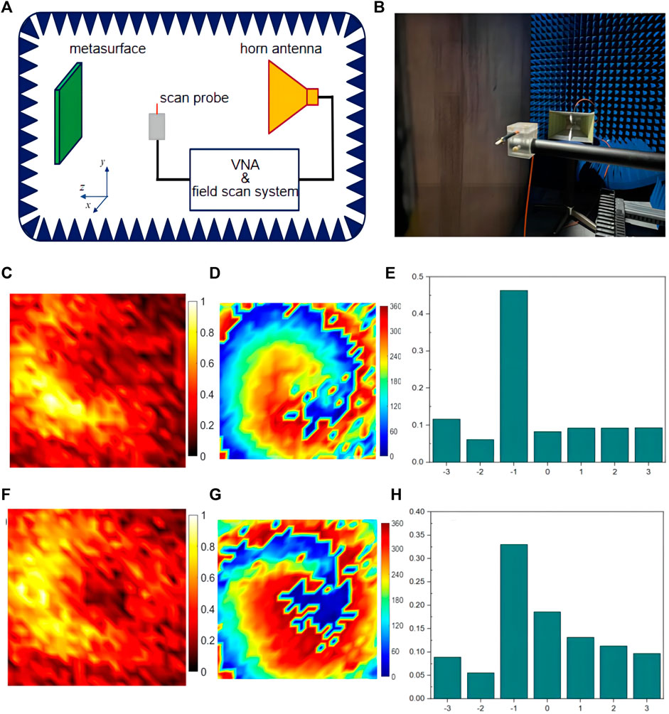
FIGURE 4. (A) The illustration of the experimental setup and (B) the horn antenna and field scan probe for the measurement; (C) (F) the amplitude distribution and (D) (G) the phase delay distribution and (E) (H) the OAM spectrum of the measured reflect wave at 8.3 GHz and 11.6 GHz, respectively.
Conclusion
In conclusion, we designed a metasurface which controls the phase delay of the EM wave through geometric phase manipulation. By coding the unit cells with different orientation angles, the metasurface robustly generates a broadband reflective OAM wave. The OAM wave at mode l = −1 was experimentally observed from 8.3 to 11.6 GHz with mode spectrum weight of 0.47 and 0.33, respectively. The broadband OAM wave realized by the reflective metasurface has high potential to improve the OAM wave utilization in the communication field.
Data availability statement
The original contributions presented in the study are included in the article/supplementary material, further inquiries can be directed to the corresponding authors.
Author contributions
Conceptualization—WZ and MZ; methodology—DL and JL; software—JT; experiment—ZZ and YZ; formal analysis—MZ and DL; discussion—BZ and WS; writing—MZ; review and editing—WS and WZ; supervision—WZ; funding acquisition—WZ. All authors have read and agreed to the published version of the manuscript.
Funding
This work was supported by the National Natural Science Foundation of China (Grant No. 61905046), Natural Science Foundation of Guangdong (Grant No. 2022A1515011354), Guangzhou Municipal Science and Technology Project (Grant No. 202102010446), the Provincial Key Laboratory of Information Photonics Technology (Guangdong University of Technology, Grant No. GKPT20-08), National Natural Science Foundation of China (Grant No. 62173101).
Conflict of interest
The authors declare that the research was conducted in the absence of any commercial or financial relationships that could be construed as a potential conflict of interest.
Publisher’s note
All claims expressed in this article are solely those of the authors and do not necessarily represent those of their affiliated organizations, or those of the publisher, the editors and the reviewers. Any product that may be evaluated in this article, or claim that may be made by its manufacturer, is not guaranteed or endorsed by the publisher.
References
1. Poynting JH. The wave motion of a revolving shaft, and a suggestion as to the angular momentum in a beam of circularly polarised light. Proc R Soc Lond Ser A, Containing Pap a Math Phys Character (1909) 82:560–7.
2. Beth RA. Mechanical detection and measurement of the angular momentum of light. Phys Rev (1936) 50:115–25. doi:10.1103/physrev.50.115
3. Coullet P, Gil L, Rocca F. Optical vortices. Opt Commun (1989) 73:403–8. doi:10.1016/0030-4018(89)90180-6
4. Allen L, Beijersbergen MW, Spreeuw RJC, Woerdman JP. Orbital angular momentum of light and the transformation of Laguerre-Gaussian laser modes. Phys Rev A (Coll Park) (1992) 45:8185–9. doi:10.1103/physreva.45.8185
5. Yao AM, Padgett MJ. Orbital angular momentum: Origins, behavior and applications. Adv Opt Photon (2011) 3:161–204. doi:10.1364/aop.3.000161
6. Zhu L, Wei X, Wang J, Zhang Z, Li Z, Zhang H, et al. Experimental demonstration of basic functionalities for 0.1-THz orbital angular momentum (OAM) communications. OFC (2014) 2014, 1–3. doi:10.1364/OFC.2014.M2I.2
7. Turnbull GA, Robertson DA, Smith GM, Allen L, Padgett MJ. The generation of free-space Laguerre-Gaussian modes at millimetre-wave frequencies by use of a spiral phaseplate. Opt Commun (1996) 127:183–8. doi:10.1016/0030-4018(96)00070-3
8. Mahmouli FE, Walker SD. 4-Gbps uncompressed video transmission over a 60-GHz orbital angular momentum wireless channel. IEEE Wirel Commun Lett (2013) 2:223–6. doi:10.1109/wcl.2013.012513.120686
9. Mari E, Spinello F, Oldoni M, Ravanelli RA, Romanato F, Parisi G. Near-field experimental verification of separation of OAM channels. IEEE Antennas Wirel Propag Lett (2015) 14:556–8. doi:10.1109/lawp.2014.2369536
10. Feng H, Ye L, Zhang Y, Li W, Chen H, Liu QH. Bidirectional multi-mode microwave vortex beam generation enabled by spoof surface plasmon polaritons. Appl Phys Lett (2020) 117:241601. doi:10.1063/5.0031209
11. Yin JY, Ren J, Zhang L, Li H, Cui TJ. Microwave vortex-beam emitter based on spoof surface plasmon polaritons. Laser Photon Rev (2018) 12:1600316. doi:10.1002/lpor.201600316
12.Generation of continuously variable-mode orbital angular momentum beams, Engineered Sci, 10 (2020) 51–7. doi:10.30919/es8d1012
13. Bai Q, Tennant A, Allen B. Experimental circular phased array for generating OAM radio beams. Electron Lett (2014) 50:1414–5. doi:10.1049/el.2014.2860
14. Guo ZG, Yang GM. Radial uniform circular antenna array for dual-mode OAM communication. IEEE Antennas Wirel Propag Lett (2017) 16:404–7. doi:10.1109/lawp.2016.2581204
15. Deng C, Zhang K, Feng Z. Generating and measuring tunable orbital angular momentum radio beams with digital control method. IEEE Trans Antennas Propag (2017) 65:899–902. doi:10.1109/tap.2016.2632532
16. Liu Q, Chen ZN, Liu Y, Li F, Chen Y, Mo Z. Circular polarization and mode reconfigurable wideband orbital angular momentum patch array antenna. IEEE Trans Antennas Propag (2018) 66:1796–804. doi:10.1109/tap.2018.2803757
17. Yu N, Genevet P, Kats MA, Aieta F, Tetienne J-P, Capasso F, et al. Light propagation with phase discontinuities: Generalized laws of reflection and refraction. Science (2011) 334:333–7. doi:10.1126/science.1210713
18. Tang S, Li X, Pan W, Zhou J, Jiang T, Ding F. High-efficiency broadband vortex beam generator based on transmissive metasurface. Opt Express (2019) 27:4281–91. doi:10.1364/oe.27.004281
19. Yang J, Zhang C, Ma HF, Zhao J, Dai JY, Yuan W, et al. Generation of radio vortex beams with designable polarization using anisotropic frequency selective surface. Appl Phys Lett (2018) 112:203501. doi:10.1063/1.5029507
20. Wang L, Liu S, Kong X, Wen Y, Liu X. Broadband vortex beam generating for multi-polarisations based on a single-layer quasi-spiral metasurface. Electron Lett (2019) 55:1168–70. doi:10.1049/el.2019.1752
21. Chen GT, Jiao YC, Zhao G. A reflectarray for generating wideband circularly polarized orbital angular momentum vortex wave. IEEE Antennas Wirel Propag Lett (2019) 18:182–6. doi:10.1109/lawp.2018.2885345
22. Yu S, Li L, Shi G, Zhu C, Zhou X, Shi Y. Design, fabrication, and measurement of reflective metasurface for orbital angular momentum vortex wave in radio frequency domain. Appl Phys Lett (2016) 108:121903. doi:10.1063/1.4944789
23. Zhang Y, Lyu Y, Wang H, Zhang X, Jin X. Transforming surface wave to propagating OAM vortex wave via flat dispersive metasurface in radio frequency. IEEE Antennas Wirel Propag Lett (2018) 17:172–5. doi:10.1109/lawp.2017.2779269
24. Huang HF, Li SN. High-Efficiency planar reflectarray with small-size for OAM generation at microwave range. IEEE Antennas Wirel Propag Lett (2019) 18:432–6. doi:10.1109/lawp.2019.2893321
25. Akram Z, Li X, Qi Z, Aziz A, Yu L, Zhu H, et al. Wideband vortex beam reflectarray design using quarter-wavelength element. IEEE Antennas Wirel Propag Lett (2019) 18:1458–62. doi:10.1109/lawp.2019.2919782
26. Xu HX, Liu H, Ling X, Sun Y, Yuan F. Broadband vortex beam generation using multimode pancharatnam–berry metasurface. IEEE Trans Antennas Propag (2017) 65:7378–82. doi:10.1109/tap.2017.2761548
27. Ran Y, Liang J, Cai T, Li H. High-performance broadband vortex beam generator using reflective Pancharatnam–Berry metasurface. Opt Commun (2018) 427:101–6. doi:10.1016/j.optcom.2018.06.041
Keywords: metasurface, metamaterial, OAM, vortex beam, broadband
Citation: Zhang M, Li D, Lin J, Zhang B, Tao J, Zhao Z, Zeng Y, Shang W and Zhang W (2022) A reflective metasurface for broadband OAM vortex wave generation. Front. Phys. 10:1042024. doi: 10.3389/fphy.2022.1042024
Received: 12 September 2022; Accepted: 26 September 2022;
Published: 13 October 2022.
Edited by:
Qinghua Song, Tsinghua University, ChinaReviewed by:
Haitao Zhao, National University of Singapore, SingaporeLip Ket Chin, City University of Hong Kong, Hong Kong SAR, China
Copyright © 2022 Zhang, Li, Lin, Zhang, Tao, Zhao, Zeng, Shang and Zhang. This is an open-access article distributed under the terms of the Creative Commons Attribution License (CC BY). The use, distribution or reproduction in other forums is permitted, provided the original author(s) and the copyright owner(s) are credited and that the original publication in this journal is cited, in accordance with accepted academic practice. No use, distribution or reproduction is permitted which does not comply with these terms.
*Correspondence: Wu Zhang, zhangwu@gzhu.edu.cn; Wenli Shang, shangwl@gzhu.edu.cn